Transducer U1a for flow sensors v-transmitters FA Transducer U2a ...
Transducer U1a for flow sensors v-transmitters FA Transducer U2a ...
Transducer U1a for flow sensors v-transmitters FA Transducer U2a ...

You also want an ePaper? Increase the reach of your titles
YUMPU automatically turns print PDFs into web optimized ePapers that Google loves.
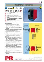
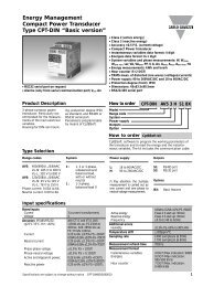
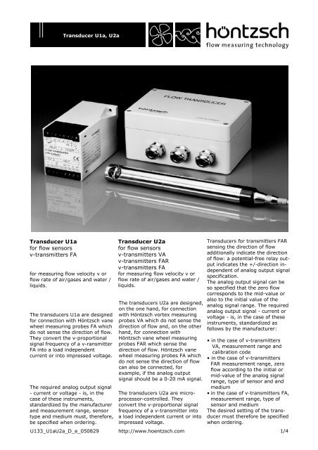
<strong>Transducer</strong> <strong>U1a</strong>, <strong>U2a</strong><br />
<strong>Transducer</strong> <strong>U1a</strong><br />
<strong>for</strong> <strong>flow</strong> <strong>sensors</strong><br />
v-<strong>transmitters</strong> <strong>FA</strong><br />
<strong>for</strong> measuring <strong>flow</strong> velocity v or<br />
<strong>flow</strong> rate of air/gases and water /<br />
liquids.<br />
The transducers <strong>U1a</strong> are designed<br />
<strong>for</strong> connection with Höntzsch vane<br />
wheel measuring probes <strong>FA</strong> which<br />
do not sense the direction of <strong>flow</strong>.<br />
They convert the v-proportional<br />
signal frequency of a v-ransmitter<br />
<strong>FA</strong> into a load independent<br />
current or into impressed voltage.<br />
The required analog output signal<br />
- current or voltage - is, in the<br />
case of these instruments,<br />
standardized by the manufacturer<br />
and measurement range, sensor<br />
type and medium must, there<strong>for</strong>e,<br />
be specified when ordering.<br />
<strong>Transducer</strong> <strong>U2a</strong><br />
<strong>for</strong> <strong>flow</strong> <strong>sensors</strong><br />
v-<strong>transmitters</strong> VA<br />
v-<strong>transmitters</strong> <strong>FA</strong>R<br />
v-<strong>transmitters</strong> <strong>FA</strong><br />
<strong>for</strong> measuring <strong>flow</strong> velocity v or<br />
<strong>flow</strong> rate of air/gases and water /<br />
liquids.<br />
The transducers <strong>U2a</strong> are designed,<br />
on the one hand, <strong>for</strong> connection<br />
with Höntzsch vortex measuring<br />
probes VA which do not sense the<br />
direction of <strong>flow</strong> and, on the other<br />
hand, <strong>for</strong> connection with<br />
Höntzsch vane wheel measuring<br />
probes <strong>FA</strong>R which sense the<br />
direction of <strong>flow</strong>. Höntzsch vane<br />
wheel measuring probes <strong>FA</strong> which<br />
do not sense the direction of <strong>flow</strong><br />
can also be connected, <strong>for</strong><br />
example, if the analog output<br />
signal should be a 0-20 mA signal.<br />
The transducers <strong>U2a</strong> are microprocessor-controlled.<br />
They<br />
convert the v-proportional signal<br />
frequency of a v-transmitter into<br />
a load independent current or into<br />
impressed voltage.<br />
<strong>Transducer</strong>s <strong>for</strong> <strong>transmitters</strong> <strong>FA</strong>R<br />
sensing the direction of <strong>flow</strong><br />
additionally indicate the direction<br />
of <strong>flow</strong>: a potential-free relay output<br />
indicates the +/-direction independent<br />
of analog output signal<br />
specification.<br />
The analog output signal can be<br />
so specified that the zero <strong>flow</strong><br />
corresponds to the mid-value or<br />
also to the initial value of the<br />
analog signal range. The required<br />
analog output signal - current or<br />
voltage - is, in the case of these<br />
instruments, standardized as<br />
follows by the manufacturer:<br />
• in the case of v-<strong>transmitters</strong><br />
VA, measurement range and<br />
calibration code<br />
• in the case of v-<strong>transmitters</strong><br />
<strong>FA</strong>R measurement range, zero<br />
<strong>flow</strong> according to the initial or<br />
mid-value of the analog signal<br />
range, type of sensor and and<br />
medium<br />
• in the case of v-<strong>transmitters</strong> <strong>FA</strong>,<br />
measurement range, type of<br />
sensor and medium<br />
The desired setting of the transducer<br />
must there<strong>for</strong>e be specified<br />
when ordering.<br />
U133_<strong>U1a</strong><strong>U2a</strong>_D_e_050829 http://www.hoentzsch.com<br />
1/4
<strong>Transducer</strong> <strong>U1a</strong>, <strong>U2a</strong><br />
Electrical Construction<br />
<strong>Transducer</strong> <strong>U1a</strong><br />
Input v/<strong>FA</strong><br />
<strong>for</strong> vane wheel measuring probes<br />
<strong>FA</strong> (v-<strong>transmitters</strong>) with 2<br />
conductors, which do not sense<br />
the direction of <strong>flow</strong>: cylinder<br />
probes, vane wheel measuring<br />
probes with measuring tube ...<br />
The input is protected in the best<br />
possible way against interference.<br />
Nevertheless, we recommend that<br />
the connection cable should be<br />
laid separately from the motor,<br />
magnet and valve wires.<br />
Output<br />
<strong>for</strong> one analog signal of choice:<br />
4-20 mA, 0-4 V, 0-10 V<br />
Current output<br />
<strong>for</strong> a burden of max. 500 Ohm<br />
with 230 VAC, 110 VAC or 24 VAC<br />
power supply, in all cases with a<br />
DC power supply <strong>for</strong> a burden of<br />
max. 300 Ohm. Burden with<br />
2-wire configuration 4-20 mA:<br />
max. 200 Ohm at 12 V<br />
max. 800 Ohm at 24 V.<br />
In all cases of external power supply (except <strong>Transducer</strong> <strong>U1a</strong> in the<br />
handle) the supply lines are electrically separated from the input<br />
and output lines of the transducer.<br />
In the case of transducers <strong>U1a</strong> and <strong>U2a</strong> in the AS102 housing, the<br />
external shield of the wires is to be connected to the cable lead-ins.<br />
<strong>Transducer</strong> <strong>U1a</strong> in the handle<br />
of the cylinder probe<br />
The integration of the transducer<br />
in the sensor presupposes that to<br />
the temperatures of the medium<br />
to be measured lie between<br />
-25 °C and +80 °C. In the case of<br />
cylinder probes the handle must<br />
have a diameter of at least<br />
25 mm. The length of a transducer<br />
handle may deviate slightly<br />
from the standard specified length<br />
(see <strong>FA</strong> data sheet). Probe<br />
extensions are possible with the<br />
customary Höntzsch extension<br />
pieces or probe tubes.<br />
PVC connection cable: length 5 m<br />
Protective system: IP 67<br />
Voltage output<br />
0-4 V or 0-10 V depending on<br />
transducer type. The reference<br />
potential <strong>for</strong> the voltage ouput is<br />
separate from the reference<br />
potential <strong>for</strong> the power supply.<br />
For this reason, the voltage output<br />
can also be used <strong>for</strong> the transfer<br />
of measured signals over greater<br />
distances.<br />
Power supply<br />
<strong>Transducer</strong>s with an analog output<br />
of 0-4 V or 0-10 V require an<br />
external power supply.<br />
<strong>Transducer</strong>s with an analog output<br />
of 4-20 mA are models requiring<br />
external power supply or 2-wire<br />
configuration, i.e. available <strong>for</strong><br />
power supply by receiver of<br />
analog signals 4-20 mA.<br />
Attention: no electrical separation!<br />
External power supply<br />
by choice:<br />
230 V +6/-10% 50/60 Hz<br />
110 V +6/-10% 50/60 Hz<br />
24V +6/-10% 50/60 Hz<br />
4.5...6 VDC<br />
10...15 VDC<br />
20...30 VDC approx. 30 mA<br />
2/4 http://www.hoentzsch.com U133_<strong>U1a</strong><strong>U2a</strong>_D_e_050829
<strong>Transducer</strong> <strong>U1a</strong>, <strong>U2a</strong><br />
<strong>Transducer</strong> <strong>U2a</strong><br />
Input v/VA<br />
<strong>for</strong> vortex measuring probes VA<br />
(v-<strong>transmitters</strong>) with 3 conductors<br />
which do not sense the direction<br />
of <strong>flow</strong>.<br />
Input v/<strong>FA</strong>R<br />
<strong>for</strong> vane wheel measuring probes<br />
<strong>FA</strong>R (v-<strong>transmitters</strong>) with 3 conductors<br />
which sense the direction<br />
of <strong>flow</strong>: cylinder probes, vane<br />
wheel measuring probes with<br />
measuring tube ...<br />
Input v/<strong>FA</strong><br />
<strong>for</strong> vane wheel measuring probes<br />
<strong>FA</strong> (v-<strong>transmitters</strong>) with 2 or 3<br />
conductors which do not sense<br />
the direction of <strong>flow</strong>: cylinder<br />
probes, vane wheel measuring<br />
probes with measuring tube ...<br />
All inputs are protected in the best<br />
possible way against interference.<br />
Nevertheless, we recommend that<br />
the connection cable should be<br />
laid separately from the motor,<br />
magnet and valve wires.<br />
Analog output<br />
<strong>for</strong> one analog signal of choice:<br />
0-20 mA, 4-20 mA, 0-4 V, 0-10 V<br />
5 s-mean values every second.<br />
Current ouput<br />
<strong>for</strong> a burden of max. 500 Ohm<br />
with 230 VAC, 110 VAC or 24 VAC<br />
power supply, in all other cases<br />
<strong>for</strong> a burden of max. 350 Ohm.<br />
Voltage output<br />
The reference potential <strong>for</strong> the<br />
voltage output is separate from<br />
the reference potential <strong>for</strong> the<br />
power supply. For this reason,<br />
the voltage output can also be<br />
used <strong>for</strong> the transfer of measured<br />
signals over greater distances.<br />
Relay output, potential-free with<br />
1 change-over contact<br />
Voltage up to 32 VDC<br />
Strength of current up to 100 mA<br />
Stray power up to 3 W<br />
Contact position at:<br />
- zero <strong>flow</strong>: mean/non-operation<br />
- insufficient power supply:<br />
mean/non-operation<br />
Delivery Program<br />
<strong>Transducer</strong> <strong>U1a</strong> <strong>U2a</strong><br />
Housing miniature LDG16<br />
IP65 AS102<br />
Handle<br />
Input<br />
v/VA<br />
v/<strong>FA</strong>R<br />
2 conductors v/<strong>FA</strong><br />
3 conductors v/<strong>FA</strong><br />
2-wire configuration 4-20 mA •<br />
Power supply<br />
230 VAC<br />
110 VAC<br />
24 VAC<br />
5 VDC<br />
12 VDC<br />
24 VDC<br />
Analog output 0-20 mA<br />
4-20 mA<br />
0-4 V<br />
0-10 V<br />
• • • •<br />
• • • •<br />
• •<br />
• • • •<br />
• •<br />
• •<br />
• •<br />
•<br />
• •<br />
• •<br />
•<br />
• • •<br />
• • • •<br />
• • •<br />
• • • • •<br />
• • • • •<br />
• •<br />
• •<br />
• •<br />
• •<br />
• •<br />
• •<br />
• •<br />
• • •<br />
• • •<br />
• • •<br />
• • • • •<br />
• • • • •<br />
• • • • •<br />
• • • • •<br />
Relay output • •<br />
Working temperature 0/+50 °C<br />
range -25/+80 °C<br />
•<br />
• • • •<br />
Power supply<br />
by choice:<br />
230 V +6/-10% 50/60 Hz<br />
110 V +6/-10% 50/60 Hz<br />
24 V +6/-10% 50/60 Hz<br />
4.5...6 VDC<br />
10...15 VDC<br />
20...30 VDC approx. 30 mA<br />
In all cases the supply lines are<br />
electrically separated from the<br />
input and output lines of the<br />
transducer.<br />
• • •<br />
• •<br />
U133_<strong>U1a</strong><strong>U2a</strong>_D_e_050829<br />
http://www.hoentzsch.com<br />
3/4
<strong>Transducer</strong> <strong>U1a</strong>, <strong>U2a</strong><br />
The transducer <strong>U1a</strong> is availabe <strong>for</strong><br />
assembly in<br />
• an aluminium housing/<br />
protective system IP 65<br />
• a miniature housing<br />
• the handle of a cylinder probe.<br />
The transducer <strong>U2a</strong> is available<br />
<strong>for</strong> assembly in<br />
• an aluminium housing/<br />
protective system IP 65<br />
• a miniature housing.<br />
Aluminium housing AS 102<br />
Protective system: housing IP 65<br />
DIN 40 050<br />
Materials:<br />
Housing: aluminium<br />
Screw caps: stainless steel,<br />
captive<br />
Gasket: groove and tongue<br />
neoprene string<br />
gasket<br />
Fastening:<br />
single-channel<br />
fastening system<br />
Line entrances:by max.3 screwed<br />
cable glands<br />
Connections: by terminal screws<br />
Overall size: L/W/H =<br />
150/100/80 mm<br />
Screwed cable glands<br />
Model:<br />
HSK-M-EMV<br />
Protective system:IP68/DIN40 040<br />
Material:<br />
nickled brass<br />
Clamp:<br />
polyamide<br />
Screw thread: PG 11<br />
Cable diameter: 5...10 mm<br />
Miniature housing LDG 16<br />
This housing is <strong>for</strong> mounting by<br />
snap fastener onto 35 mm standard<br />
assembly rails according to<br />
DIN 46 277 and DIN EN 50 022<br />
or screw fitting. The housing is an<br />
insulating case corresponding to<br />
the specifications of the machine<br />
and automobile industry with a<br />
max. of 16 protected terminals as<br />
per VDE 0100 and VGB 4.<br />
Protective system: housing IP 40<br />
terminals IP 20<br />
Material: Macrolon<br />
Connections: screwed terminals<br />
Overall size: H/W/D =<br />
75/55/110 mm<br />
CE Con<strong>for</strong>mity<br />
<strong>Transducer</strong>s <strong>U1a</strong> and <strong>U2a</strong> with<br />
the corresponding <strong>sensors</strong> do not<br />
cause electromagnetic interference<br />
outside the permissible<br />
limiting values.<br />
Höntzsch GmbH<br />
Gottlieb-Daimler-Straße 37<br />
D-71334 Waiblingen (Hegnach)<br />
Telefon +49 7151 / 17 16-0<br />
Telefax +49 7151 / 5 84 02<br />
E-Mail info@hoentzsch.com<br />
Internet www.hoentzsch.com<br />
<strong>Transducer</strong>s <strong>U1a</strong> and <strong>U2a</strong> in LDG<br />
16 housing are resistant to<br />
interference when<br />
• they are accommodated in a<br />
conductive housing, e.g. service<br />
cabinet<br />
• the cable entries are CE-correct<br />
• the appertaining installation<br />
instructions are adhered to.<br />
On request transducers can be<br />
supplied in an LDG housing which<br />
is already in con<strong>for</strong>mity with CE.<br />
U133_<strong>U1a</strong><strong>U2a</strong>_D_e_050829 http://www.hoentzsch.com<br />
4/4