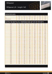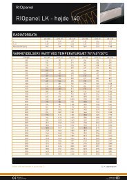
Radiator valve datasheet - RIOpanel
Radiator valve datasheet - RIOpanel
Radiator valve datasheet - RIOpanel

Create successful ePaper yourself
Turn your PDF publications into a flip-book with our unique Google optimized e-Paper software.
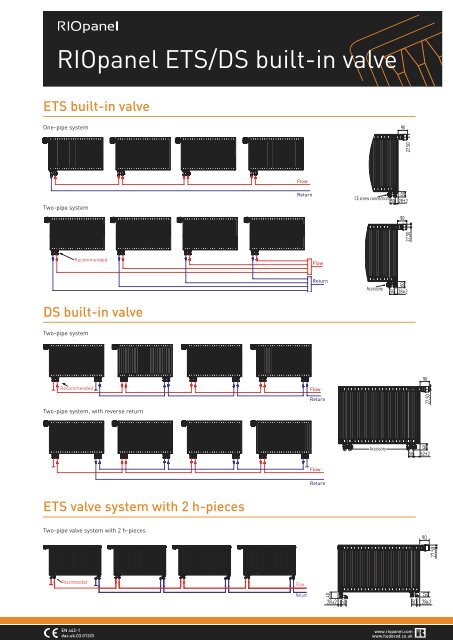
<strong>RIOpanel</strong> ETS/DS built-in <strong>valve</strong><br />
ETS built-in <strong>valve</strong><br />
One-pipe system<br />
Flow<br />
Two-pipe system<br />
Return<br />
CE screw connection<br />
90<br />
27,50<br />
Recommended<br />
Flow<br />
Return<br />
Accessory<br />
60<br />
50 28±2<br />
DS built-in <strong>valve</strong><br />
Two-pipe system<br />
Recommended<br />
Flow<br />
Return<br />
Two-pipe system, with reverse return<br />
Accessory<br />
Flow<br />
Return<br />
ETS <strong>valve</strong> system with 2 h-pieces<br />
Two-pipe <strong>valve</strong> system with 2 h-pieces<br />
90<br />
27,5<br />
Recommended<br />
Flow<br />
Return<br />
60<br />
28 ±2 50<br />
50<br />
50<br />
28±2<br />
EN 442-1<br />
das.uk.03.013/0<br />
www.riopanel.com<br />
www.hudevad.co.uk
<strong>RIOpanel</strong> ETS/DS built-in <strong>valve</strong><br />
Pressure drop diagram<br />
Forindstilling ETS/DS<br />
One-pipe system<br />
Pressure drop diagram for CE screw connection<br />
Pressure drop p (mbar)<br />
10 3<br />
9<br />
8<br />
7<br />
6<br />
5<br />
4<br />
3<br />
2<br />
<strong>Radiator</strong>share<br />
50%<br />
45%<br />
40%<br />
35%<br />
30%<br />
1<br />
1,5<br />
1,75<br />
2,25<br />
2,5<br />
10 3<br />
9<br />
8<br />
7<br />
6<br />
5<br />
4<br />
3<br />
2<br />
Pressure drop p (kPa)<br />
1. Remove the protective cap or the thermostatic<br />
sensor<br />
2. Lift the setting ring<br />
3. Turn the setting ring anti-clockwise until the preferred<br />
scale value aligns with the reference point<br />
4. Let go of the setting ring<br />
10 2<br />
9<br />
8<br />
7<br />
6<br />
5<br />
10 2<br />
9<br />
8<br />
7<br />
6<br />
5<br />
4<br />
4<br />
3<br />
2<br />
2<br />
10 2 2 3 4 5 6 7 8 9 10 3 2<br />
Flow (l/h)<br />
The lines of the diagram correspond to the number of turns of the<br />
bypass spindle (screw). Close the screw completely (right stop) and<br />
then unscrew it the number of turns required to obtain the desired<br />
radiator share. The factory-setting of the CE screw connection corresponds<br />
to a radiator share of approx. 35%.<br />
Presetting can be selected between 1 and 7 in increments<br />
of 0.5. At setting “N” the <strong>valve</strong> is fully open.<br />
Setting in the shaded areas of the drawing above<br />
should be avoided. When the thermostatic sensor has<br />
been installed, the presetting is locked – and protected<br />
against unintended adjustment. In a one-pipe<br />
system, the setting “N” must be used.<br />
Adjustment nomograms for two-pipe systems ETS/DS<br />
3<br />
013G0380<br />
For large volume flow rates RA-N<br />
013G0381<br />
For small volume flow rates RA-U<br />
[bar]<br />
[kPa]<br />
RA 2000 at a P band between 0.5 K and 2 K<br />
Characteristic: Presetting ring RED: RA-N<br />
RA 2000 at a P band between 0.5 K and 2 K<br />
Characteristic: Presetting ring YELLOW: RA-U<br />
EN 442-1<br />
das.uk.02.012/0<br />
www.riopanel.com<br />
www.hudevad.co.uk