Twin Wall, Insulated Stainless Steel Multi-Fuel Chimney System
Twin Wall, Insulated Stainless Steel Multi-Fuel Chimney System
Twin Wall, Insulated Stainless Steel Multi-Fuel Chimney System

Create successful ePaper yourself
Turn your PDF publications into a flip-book with our unique Google optimized e-Paper software.
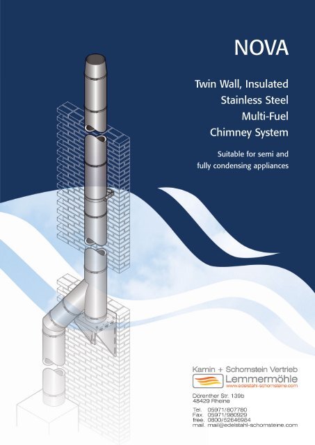
NOVA<br />
<strong>Twin</strong> <strong>Wall</strong>, <strong>Insulated</strong><br />
<strong>Stainless</strong> <strong>Steel</strong><br />
<strong>Multi</strong>-<strong>Fuel</strong><br />
<strong>Chimney</strong> <strong>System</strong><br />
Suitable for semi and<br />
fully condensing appliances
INTRODUCTION<br />
2<br />
Nova Family Products<br />
Nova SM and Nova SF are the first of a family<br />
of new products to be made available in all of<br />
the extensive markets served by SF Limited.<br />
Nova SC, a 50mm annulus version of Nova SM<br />
is also available to special order, and further<br />
details can be provided on request.<br />
DESCRIPTION<br />
Nova SM and Nova SF are prefabricated, factory made<br />
twin-wall insulated stainless steel chimney systems of<br />
identical manufacture excepting the insulation<br />
material. The fully welded construction combined with<br />
a high level of insulation, provides the minimum level<br />
of performance required of modern high efficiency<br />
combustion equipment burning oil, gas and solid fuel.<br />
The construction provides a high thermal resistance<br />
which ensures rapid stabilisation of the flue gas<br />
temperature and draught, whilst maintaining a<br />
relatively low temperature on the external surface of<br />
the chimney. The insulation format is dependant on the<br />
fuel type and combustion equipment application which<br />
the chimney serves. Please read the Specification<br />
section below.<br />
Both versions are designed for internal and external<br />
application, and with natural draught or positive<br />
pressure at low temperatures (up to 200ºC) and for<br />
appliances with flue-gas temperatures up to 540ºC<br />
when subjected to continuous firing, and 760ºC when<br />
subjected to short term firing.<br />
Nova SM system is available in 13 diameters from<br />
100mm to 600mm, and Nova SF in 8 diameters from<br />
100mm to 350mm. A range of Lengths and fittings as<br />
well as various support components, enable flexibility<br />
in design and application. However, actual utilisation<br />
of the system must be kept within the limitations<br />
identified in this literature and any additional National<br />
Regulations and Standards.<br />
Construction<br />
The system is available with two insulation<br />
specifications: - Nova SM and Nova SF. For either<br />
version, where residentially applied for oil or solid<br />
fuel use, and to comply with British Standards and<br />
Building Regulation requirements, special floor<br />
penetration components as described in this literature<br />
must be used for such application. UK Building<br />
Regulations dictate similar requirements for any<br />
other prefabricated metal chimney system. In both<br />
cases the inner liner, and the outer casing is made<br />
from stainless steel and the annulus between the two<br />
is filled with high quality insulation. This provides safe<br />
operation at high temperatures and also maintains the<br />
flue gas temperature throughout the chimney length.<br />
The weatherproof outer casing carries the structural<br />
load of the insulated components.<br />
The joint design is innovative and unique. Elements<br />
are assembled using a barbed coupler joint which<br />
engage by a simple twist action and the joint is<br />
secured with a Locking Band. The outer casing is<br />
joined to both the male and female barbed couplers,<br />
the number of barbs dependant on product diameter.<br />
The inner liner, which forms an integral part of the<br />
welded male coupler, is free to expand or contract<br />
as the flue gas temperature varies.<br />
Application<br />
As heating equipment is increasingly evolving to<br />
exploit the latent heat in flue gases, condensation<br />
in the flue is inevitable. Conventional chimneys are<br />
unsuitable for the discharge of flue gases at low<br />
temperatures, which is why the system, particularly<br />
when used on natural draught applications, overcomes<br />
problems associated with moisture formation in<br />
the flue.<br />
An optional joint seal is available where Nova SM<br />
is applied for low temperature applications of up to<br />
200ºC. With the joint seals fitted, Nova SM becomes<br />
moisture and pressure resistant making it ideal for<br />
serving appliances that operate under a positive<br />
pressure (1000 Pa or 4”wg.) and/or condensing<br />
conditions. When the system, is used without the<br />
Joint Seal, it is suitable for condensing equipment,<br />
providing there is a negative pressure within the flue,<br />
and any sloping runs are angled at not less than 5º<br />
from the horizontal. Any condensation which forms<br />
inside the system, must be allowed to run into either<br />
a condensate drainage component, or drainage<br />
facilities which are part of the equipment to which<br />
the system is connected.<br />
Nova SM has an<br />
identification<br />
label on the<br />
inner liner.<br />
Nova SF has an<br />
identification<br />
label on the<br />
outer casing.<br />
Specification Identification<br />
Each of the two versions has different packaging labels<br />
for identification purposes. Nova SM has blue labels,<br />
and Nova SF gold labels. However as the insulated<br />
components look alike, Nova SF has a clear plastic<br />
label on the external skin which clearly identifies the<br />
product as such. Nova SM has an identification label<br />
on the inside liner. See the illustration.<br />
Nova SM Specification Available in the full 100mm -<br />
600mm diameter range. The insulation is a high grade<br />
mineral fibre which enables the chimney to be used<br />
with all fuels, subject to the following.<br />
Gas fired equipment<br />
Although technically, the outer skin may be safely<br />
positioned in contact with non-structural combustible<br />
materials, all the support components provide a<br />
minimum 50mm air gap clearance from supporting<br />
surfaces.<br />
Oil-fired equipment<br />
A minimum 50mm air gap clearance must be<br />
maintained from the chimney to any combustible<br />
material, and where residentially applied, Building<br />
Regulations demand that prefabricated metal<br />
chimney systems have demonstrated compliance<br />
with BS4543: Part 3. Nova SM diameters 100mm to<br />
200mm are Kitemarked to BS4543: Part 3.<br />
Solid fuel equipment.<br />
This specification may only be used with solid fuel<br />
combustion equipment under the following conditions.
1. Where Nova SM is constructed within and passes<br />
through non-combustible structures and is enclosed<br />
in a fire rated shaft.<br />
2. Where Nova SM serves a solid fuel appliance,<br />
which is located against an external noncombustible<br />
wall, and the chimney passes<br />
immediately through that wall so that it becomes<br />
externally located, and any internal chimney parts<br />
are provided with additional clearances from any<br />
combustible materials. SF Limited consider that this<br />
latter arrangement is both safe and fit for purpose, and<br />
are entitled to state such within the dictates of England<br />
and Wales Building Regulations, Approved document<br />
J, Northern Ireland Technical Booklet L and the<br />
Building Standards (Scotland) Regulations, Section F.<br />
Figure 6 in the installation instructions on page 19<br />
illustrates the arrangement.<br />
For residential application and where a Nova system<br />
is constructed to pass through combustible floor or<br />
wall structures, Nova SF, as described in the following<br />
specification, must be applied.<br />
Nova SF Specification Available as standard for the<br />
100 to 200mm diameter range, and to order for 250mm<br />
- 350 range. The insulation is a high grade fibre<br />
reinforced volatilised mineral powder which enables<br />
the chimney to be used with all fuels. However it is<br />
specifically intended for, and must be used where the<br />
system is internally applied on any solid fuel<br />
combustion equipment where the chimney is located<br />
adjacent to combustible materials and/or passes<br />
through timber floor construction. A minimum 50mm<br />
air gap clearance must be maintained from the<br />
chimney to any combustible material. Building<br />
Regulations demand that prefabricated metal chimney<br />
systems used with solid fuel appliances must have<br />
demonstrated compliance with BS4543: Part 2, and<br />
are installed in accordance with and BS7566.<br />
Nova SF diameters 130mm to 200mm are Kitemarked<br />
to BS4543: Parts 2 and 3.<br />
Where using either specification for diameters<br />
250mm and above, and the system is to pass<br />
through combustible floor structures, please<br />
consult SF Limited for additional guidance.<br />
Fire Rating<br />
Nova SM has been assessed by the Loss Prevention<br />
Council for fire resistance. A fire rating of two hours<br />
can be achieved in accordance with the stability and<br />
integrity criteria of BS476: Part 20, 1987 for duct type B.<br />
Design Information<br />
Comprehensive chimney sizing and design related<br />
to the application of the Nova system is available<br />
on request.<br />
The thermal resistance for the insulated wall of Nova<br />
SM is 0.3m2K/W, relative to a hot face temperature<br />
of 200ºC.<br />
High efflux velocities should be attained in the system<br />
design to reduce pollution at ground level. There are<br />
pertinent Clean Air Act regulations in the UK. For<br />
further information, please read the section on Clean<br />
Air Act Requirements.<br />
Product Guarantee<br />
Depending on application and country where used,<br />
the SF Limited Nova Family products benefit from<br />
extended guarantee periods, for which written<br />
conditions are available on request.<br />
Note<br />
Those components within the system range which are<br />
fabricated from only a single skin, can be vulnerable<br />
when exposed to the products of combustion from<br />
solid fuel appliances. In the majority of cases, an openended<br />
terminal better suits appliance performance,<br />
but it is acknowledged that on occasions, other types<br />
of terminal from the range have to be used to reduce<br />
rain entry. Condensate Collectors and Locking Plugs<br />
when used with solid fuel are also vulnerable to flue<br />
gas by-products, particularly if the chimney is not<br />
regularly maintained and cleaned.<br />
Such components are considered sacrificial and their<br />
life expectancy will vary dependant on application,<br />
location, maintenance and fuel usage. For that reason,<br />
Terminals, Condensate Collectors and Locking Plugs<br />
are not covered by any guarantee other than for a<br />
twelve month period against defective manufacture.<br />
It should also be borne in mind that chemically<br />
contaminated combustion air will affect the durability<br />
and therefore longevity of both the chimney and the<br />
appliance it serves.<br />
SF Limited cannot accept responsibility for any<br />
installation, which seeks to combine Nova SM or<br />
Nova SF with any other form of chimney construction,<br />
excepting application where appropriate advice has<br />
been provided by SF Limited.<br />
Clean Air Act requirements<br />
In the UK, any chimney system must comply with the<br />
Clean Air Act Memorandum 1956, including those<br />
serving balanced draught / room-sealed boiler plant.<br />
This statute applies to all commercial and industrial<br />
boiler plant as well as diesel generators, and dictates<br />
the minimum height above which the chimney must<br />
discharge combustion gases into the atmosphere in<br />
relation to surrounding buildings, irrespective of the<br />
chimney design, type, or termination detail.<br />
The appropriate heights must be calculated to take<br />
into account the combined emissions from all items<br />
of plant at one location.<br />
Additional information can be obtained from the<br />
National Society for Clean Air, (01213 336313), in their<br />
publications, “The Pollution Handbook” and “Air<br />
Pollution Aspects of Room-Sealed Boiler Flue <strong>System</strong>s”.<br />
A Technical Guidance Note entitled “D1 - Guidelines on<br />
Discharge Stack Heights for Polluting Emissions”,<br />
published by HM Inspectorate of Pollution, obtainable<br />
from HMSO, also provides useful information.<br />
SF Limited have available a publication entitled “The<br />
Clean Air Act. <strong>Chimney</strong> Discharge Heights-what you<br />
need to know”. Please ask for details.<br />
Approvals<br />
Nova SM<br />
Diameters 100mm to 200mm inclusive are manufactured,<br />
tested and Kitemarked to BS 4543: Part 3, 1990. Also to<br />
German DIN 18160 and to French Afnor requirements.<br />
The system has also been fully assessed and approved<br />
by the institute Fur Bau Technik in Germany in<br />
accordance with the DIN guidelines for moisture<br />
resistant chimney systems.<br />
Nova SF<br />
Diameters 130mm to 200mm inclusive are manufactured,<br />
tested and Kitemarked to BS 4543: Parts 2 and 3, 1990.<br />
Both Nova systems are manufactured under a Quality<br />
Assurance Scheme Certificate No. FM01079<br />
administered by British Standards in accordance with<br />
BS EN ISO 9001:2000.<br />
3
TYPICAL APPLICATIONS<br />
BS 4543: Parts 2 and 3<br />
FM01079<br />
Commercial or<br />
Industrial header<br />
application<br />
Commercial or<br />
Industrial application<br />
Commercial or<br />
Industrial mast<br />
application<br />
Residential<br />
application<br />
The information contained in this brochure was accurate at the time of publishing. However, the company reserves the<br />
right to introduce at any time modifications and change of details as may be necessary. To avoid any misunderstandings,<br />
interested parties should contact the company to confirm whether any material alterations have been made since the date<br />
of this brochure, which will be found on the back page.<br />
4
INDIVIDUAL COMPONENTS<br />
500mm – nominal<br />
500mm – nominal<br />
A<br />
D<br />
B<br />
C<br />
250mm<br />
LENGTHS<br />
Straight Lengths<br />
Straight lengths are available in<br />
nominal installed lengths of 1000mm,<br />
500mm, 300mm and 120mm.<br />
Size Nova SM Code numbers<br />
1000mm 500mm 300mm 120mm<br />
100mm 4575004 4575104 4575204 4575304<br />
130mm 4575005 4575105 4575205 4575305<br />
150mm 4575006 4575106 4575206 4575306<br />
180mm 4575007 4575107 4575207 4575307<br />
200mm 4575008 4575108 4575208 4575308<br />
250mm 4575010 4575110 4575210 4575310<br />
300mm 4575012 4575112 4575212 4575312<br />
350mm 4575014 4575114 4575214 4575314<br />
400mm 4575016 4575116 4575216 4575316<br />
450mm 4575018 4575118 4575218 4575318<br />
500mm 4575020 4575120 4575220 4575320<br />
550mm 4575022 4575122 4575222 4575322<br />
600mm 4575024 4575124 4575224 4575324<br />
Size Nova SF Code numbers<br />
1000mm 500mm 300mm 120mm<br />
100mm 4545004 4545104 4545204 4545304<br />
130mm 4545005 4545105 4545205 4545305<br />
150mm 4545006 4545106 4545206 4545306<br />
180mm 4545007 4545107 4545207 4545307<br />
200mm 4545008 4545108 4545208 4545308<br />
250mm 4545010 4545110 4545210 4545310<br />
300mm 4545012 4545112 4545212 4545312<br />
350mm 4545014 4545114 4545214 4545314<br />
Inspection Length – Standard<br />
Used to provide access for inspection<br />
or cleaning via an insulated lockable<br />
door. NB. Negative flue pressure<br />
applications only.<br />
Size<br />
Code number<br />
100mm 4576204<br />
130mm 4576205<br />
150mm 4576206<br />
180mm 4576207<br />
200mm 4576208<br />
250mm 4576210<br />
300mm 4576212<br />
350mm 4576214<br />
400mm 4576216<br />
450mm 4576218<br />
500mm 4576220<br />
550mm 4576222<br />
600mm 4576224<br />
Inspection Length – Metu<br />
Used to provide access for inspection<br />
or cleaning. To be used where the<br />
flue gases are likely to condense and<br />
where the flue gas temperature does<br />
not exceed 200°C.<br />
Size Dimensions Code<br />
A B C D number<br />
100mm 220 130 180 70 4576304<br />
130mm 220 160 180 80 4576305<br />
150mm 240 180 200 100 4576306<br />
180mm 240 180 200 100 4576307<br />
200mm 240 180 200 100 4576308<br />
250mm 240 180 200 100 4576310<br />
300mm 240 180 200 100 4576312<br />
350mm 240 180 200 100 4576314<br />
150mm<br />
Long 350mm–550mm<br />
Short 250mm–400mm<br />
100mm-350mm Diameter<br />
600mm–900mm<br />
Probe Length<br />
Fitted with a cover over an M16<br />
tapped hole and plug, which provides<br />
access for flue gas testing. To be used<br />
where the flue gases are likely to<br />
condense and where the flue gas<br />
temperature does not exceed 200°C.<br />
Size<br />
Code number<br />
100mm 4576704<br />
130mm 4576705<br />
150mm 4576706<br />
180mm 4576707<br />
200mm 4576708<br />
250mm 4576710<br />
300mm 4576712<br />
350mm 4576714<br />
400mm 4576716<br />
450mm 4576718<br />
500mm 4576720<br />
550mm 4576722<br />
600mm 4576724<br />
Adjustable Length<br />
As the insulation density will vary<br />
with application, these components<br />
should always be located at least<br />
100mm from any combustible<br />
material. Neither version is load<br />
bearing. In both cases, the insulation<br />
material is supplied for insertion into<br />
its annulus once the installed length<br />
has been determined.<br />
100mm 350mm range<br />
Telescopic sections designed to<br />
provide small increments in installed<br />
length. There is a short and long<br />
version. As the liner of this component<br />
may, depending on degree of<br />
adjustment, project into the<br />
component below, it should only be<br />
connected to a Straight Length. For<br />
pressure applications, it will need to<br />
be used with the separately ordered<br />
Adjustable Length Locking Band and<br />
Seal, code 45798##<br />
400mm 600mm range<br />
Likewise designed for installed linear<br />
adjustment. It has no seal option, and<br />
the same installation/application<br />
criteria apply. It is adjusted to length<br />
and secured with supplied self<br />
tapping screws.<br />
Long version for 100mm–350mm size<br />
Size<br />
Code number<br />
100mm 4574604<br />
130mm 4574605<br />
150mm 4574606<br />
180mm 4574607<br />
200mm 4574608<br />
250mm 4574610<br />
300mm 4574612<br />
350mm 4574614<br />
Short version for 100mm–350mm size<br />
Size<br />
Code number<br />
100mm 4576604<br />
130mm 4576605<br />
150mm 4576606<br />
180mm 4576607<br />
200mm 4576608<br />
250mm 4576610<br />
300mm 4576612<br />
350mm 4576614<br />
Version for 400mm–600mm size<br />
Size<br />
Code number<br />
400mm 4576616<br />
450mm 4576618<br />
500mm 4576620<br />
550mm 4576622<br />
600mm 4576624<br />
5
150mm<br />
A<br />
Duct Drain<br />
Used in a horizontal or inclined<br />
position to trap condensate and<br />
permit drainage. It is fitted with<br />
a BSP stainless steel thread.<br />
Size Dimension Code<br />
A<br />
number<br />
100mm 1” BSP 4576804<br />
130mm 1” BSP 4576805<br />
150mm 1” BSP 4576806<br />
180mm 1” BSP 4576807<br />
200mm 1” BSP 4576808<br />
250mm 1” BSP 4576810<br />
300mm 1” BSP 4576812<br />
350mm 1” BSP 4576814<br />
400mm 2” BSP 4576816<br />
450mm 2” BSP 4576818<br />
500mm 2” BSP 4576820<br />
550mm 2” BSP 4576822<br />
600mm 2” BSP 4576824<br />
Locking Band<br />
The Locking Band must be used on<br />
all joints, and is ordered separately,<br />
OTHER than where it is identified<br />
as supplied with a component.<br />
Size<br />
Code number<br />
100mm 4578604<br />
130mm 4578605<br />
150mm 4578606<br />
180mm 4578607<br />
200mm 4578608<br />
250mm 4578610<br />
300mm 4578612<br />
350mm 4578614<br />
400mm 4578616<br />
450mm 4578618<br />
500mm 4578620<br />
550mm 4578622<br />
600mm 4578624<br />
Liner Locking Band & Seal<br />
This component is required for the<br />
Adjustable Length. It should always<br />
be used where the flue gases are<br />
likely to condense and where the flue<br />
gas temperature does not exceed<br />
200°C. It provides a seal at the<br />
overlap of the sliding joints, and is<br />
independent of the normal Joint<br />
Sealing Ring. The Locking Band MUST<br />
only be applied one way round. See<br />
Installation Instructions on page 16.<br />
Size<br />
Code number<br />
100mm 4579804<br />
130mm 4579805<br />
150mm 4579806<br />
180mm 4579807<br />
200mm 4579808<br />
250mm 4579810<br />
300mm 4579812<br />
350mm 4579814<br />
400mm 4579816<br />
450mm 4579818<br />
500mm 4579820<br />
550mm 4579822<br />
600mm 4579824<br />
130mm<br />
Section<br />
A<br />
130mm<br />
Joint Sealing Ring<br />
This optional component is available<br />
for diameters between 100mm and<br />
350mm, and is located in the joint<br />
as explained in the Installation<br />
Instructions on page 16.<br />
The Seal provides a moisture and gas<br />
resistant seal to a pressure of 1000<br />
Pascal, (4” wg.) The seal would<br />
normally be fitted to any application<br />
where the flue gases are likely to<br />
condense and where the flue gas<br />
temperature does not exceed 200°C.<br />
Size<br />
Code number<br />
100mm 4578004<br />
130mm 4578005<br />
150mm 4578006<br />
180mm 4578007<br />
200mm 4578008<br />
250mm 4578010<br />
300mm 4578012<br />
350mm 4578014<br />
400mm 4578016<br />
450mm 4578018<br />
500mm 4578020<br />
550mm 4578022<br />
600mm 4578024<br />
FITTINGS<br />
Adaptor<br />
Designed to enable connection from<br />
the appliance as well as Supra.<br />
Size<br />
Code number<br />
100mm 4579604<br />
130mm 4579605<br />
150mm 4579606<br />
180mm 4579607<br />
200mm 4579608<br />
250mm 4579610<br />
300mm 4579612<br />
350mm 4579614<br />
400mm 4579616<br />
450mm 4579618<br />
500mm 4579620<br />
550mm 4579622<br />
600mm 4579624<br />
Female Adaptor<br />
Designed to enable connection from<br />
Nova SM to Supra.<br />
Size Dimension Code<br />
A<br />
number<br />
100mm 63 4579704<br />
130mm 63 4579705<br />
150mm 63 4579706<br />
180mm 42 4579707<br />
200mm 42 4579708<br />
250mm 42 4579710<br />
300mm 42 4579712<br />
350mm 42 4579714<br />
6
Nova SM<br />
A<br />
SM & SM W<br />
SM & SM W<br />
B<br />
Nova SM<br />
Nova to SM Adaptors<br />
There are two versions, both of which<br />
have an installed length of 75mm.<br />
They are designed to allow<br />
connection of Nova to existing SM and<br />
SM W installations.<br />
Size<br />
Code number<br />
A B<br />
127/130mm 4574805 4574705<br />
152/150mm 4574806 4574706<br />
178/180mm 4574807 4574707<br />
203/200mm 4574808 4574708<br />
254/250mm 4574810 4574710<br />
304/300mm 4574812 4574712<br />
355/350mm 4574814 4574714<br />
15° Elbow<br />
Provides a 15° change of direction<br />
from the vertical. See the technical<br />
data on page 15 for Elbow dimensions.<br />
Size<br />
Code numbers<br />
Nova SM Nova SF<br />
100mm 4575404 4545404<br />
130mm 4575405 4545405<br />
150mm 4575406 4545406<br />
180mm 4575407 4545407<br />
200mm 4575408 4545408<br />
250mm 4575410 4545410<br />
300mm 4575412 4545412<br />
350mm 4575414 4545414<br />
400mm 4575416 –<br />
450mm 4575418 –<br />
500mm 4575420 –<br />
550mm 4575422 –<br />
600mm 4575424 –<br />
30° Elbow<br />
Provides a 30° change of direction<br />
from the vertical. See the technical<br />
data on page 15 for Elbow dimensions.<br />
Size<br />
Code numbers<br />
Nova SM Nova SF<br />
100mm 4575504 4545504<br />
130mm 4575505 4545505<br />
150mm 4575506 4545506<br />
180mm 4575507 4545507<br />
200mm 4575508 4545508<br />
250mm 4575510 4545510<br />
300mm 4575512 4545512<br />
350mm 4575514 4545514<br />
400mm 4575516 –<br />
450mm 4575518 –<br />
500mm 4575520 –<br />
550mm 4575522 –<br />
600mm 4575524 –<br />
40° Elbow<br />
Provides a 40° change of direction<br />
from the vertical. See the technical<br />
data on page 15 for Elbow dimensions.<br />
Size<br />
Code number<br />
100mm 4575604<br />
130mm 4575605<br />
150mm 4575606<br />
180mm 4575607<br />
200mm 4575608<br />
250mm 4575610<br />
300mm 4575612<br />
350mm 4575614<br />
400mm 4575616<br />
450mm 4575618<br />
500mm 4575620<br />
550mm 4575622<br />
600mm 4575624<br />
A<br />
A<br />
B<br />
A<br />
Dimension lines relate<br />
to centre line of the<br />
flue.<br />
B<br />
A<br />
Dimension lines relate<br />
to centre line of the<br />
flue.<br />
C<br />
C<br />
45° Elbow<br />
Provides a 45° change of direction.<br />
See the technical data on page 15 for<br />
Elbow dimensions.<br />
Size<br />
Code numbers<br />
Nova SM Nova SF<br />
100mm 4575704 4545704<br />
130mm 4575705 4545705<br />
150mm 4575706 4545706<br />
180mm 4575707 4545707<br />
200mm 4575708 4545708<br />
250mm 4575710 4545710<br />
300mm 4575712 4545712<br />
350mm 4575714 4545714<br />
400mm 4575716 –<br />
450mm 4575718 –<br />
500mm 4575720 –<br />
550mm 4575722 –<br />
600mm 4575724 –<br />
85° Elbow<br />
Provides an 85° change of direction<br />
from the vertical.<br />
Size Dimensions Code<br />
A B C number<br />
100mm 91 126 192 4575804<br />
130mm 98 136 207 4575805<br />
150mm 102 144 217 4575806<br />
180mm 108 156 233 4575807<br />
200mm 112 165 244 4575808<br />
250mm 123 185 270 4575810<br />
300mm 133 206 296 4575812<br />
350mm 143 227 323 4575814<br />
400mm 154 247 350 4575816<br />
450mm 164 268 376 4575818<br />
500mm 174 289 403 4575820<br />
550mm 185 310 430 4575822<br />
600mm 195 330 456 4575824<br />
90° Elbow<br />
Provides a 90° change of direction.<br />
Size Dimensions Code<br />
A B C number<br />
100mm 91 126 180 4575904<br />
130mm 98 136 193 4575905<br />
150mm 102 144 204 4575906<br />
180mm 108 156 219 4575907<br />
200mm 112 165 229 4575908<br />
250mm 123 185 254 4575910<br />
300mm 133 206 279 4575912<br />
350mm 143 227 304 4575914<br />
400mm 154 247 329 4575916<br />
450mm 164 268 354 4575918<br />
500mm 174 289 379 4575920<br />
550mm 185 310 404 4575922<br />
600mm 195 330 429 4575924<br />
7
A<br />
B<br />
A<br />
Dimension lines relate<br />
to centre line of the<br />
flue.<br />
C<br />
85° Inspection Elbow<br />
Provides an 85° change of direction<br />
from the vertical, and incorporates a<br />
cleaning access. To be used where<br />
the flue gases are likely to condense<br />
and where the flue gas temperature<br />
does not exceed 200°C.<br />
Size Dimensions Code<br />
A B C number<br />
100mm 91 272 291 4576004<br />
130mm 98 272 306 4576005<br />
150mm 102 282 318 4576006<br />
180mm 108 282 325 4576007<br />
200mm 112 282 330 4576008<br />
250mm 123 282 342 4576010<br />
300mm 133 282 352 4576012<br />
350mm 143 282 363 4576014<br />
135° Tee<br />
Used at the base of a vertical flue, or<br />
for horizontal header configurations.<br />
Size Dimensions Nova SM<br />
A B Code number<br />
100mm 500 325 4576504<br />
130mm 500 340 4576505<br />
150mm 500 375 4576506<br />
180mm 750 420 4576507<br />
200mm 750 450 4576508<br />
250mm 750 520 4576510<br />
300mm 750 585 4576512<br />
350mm 1000 650 4576514<br />
400mm 1000 675 4576516<br />
450mm 1000 750 4576518<br />
500mm 1000 810 4576520<br />
550mm 1000 785 4576522<br />
600mm 1000 850 4576524<br />
A<br />
A<br />
B<br />
A<br />
Dimension lines relate<br />
to centre line of the<br />
flue.<br />
B<br />
A<br />
Dimension lines relate<br />
to centre line of the<br />
flue.<br />
C<br />
C<br />
90° Inspection Elbow –<br />
Metu Seal<br />
Provides a 90° change of direction,<br />
and incorporates a cleaning access.<br />
To be used where the flue gases are<br />
likely to condense and where the flue<br />
gas temperature does not exceed<br />
200°C.<br />
Size Dimensions Code<br />
A B C number<br />
100mm 91 272 283 4576104<br />
130mm 98 272 290 4576105<br />
150mm 102 282 301 4576106<br />
180mm 108 282 307 4576107<br />
200mm 112 282 311 4576108<br />
250mm 123 282 322 4576110<br />
300mm 133 282 332 4576112<br />
350mm 143 282 342 4576114<br />
90° Inspection Elbow –<br />
Extended Branch<br />
Available in the full diameter range,<br />
provides a 90º change of direction.<br />
This component incorporates a female<br />
branch which can be closed off with a<br />
Locking Plug. For condensing and<br />
pressure applications, it can be used<br />
with the Joint Sealing ring, with same<br />
temperature limitations applying.<br />
Size Dimensions Code<br />
A B C number<br />
100mm 91 272 283 4574904<br />
130mm 98 272 290 4574905<br />
150mm 102 282 301 4574906<br />
180mm 108 282 307 4574907<br />
200mm 112 282 311 4574908<br />
250mm 123 282 322 4574910<br />
300mm 133 282 332 4574912<br />
350mm 143 282 342 4574914<br />
400mm 154 370 329 4574916<br />
450mm 164 392 354 4574918<br />
500mm 174 424 379 4574920<br />
550mm 185 460 404 4574922<br />
600mm 195 488 429 4574924<br />
A<br />
B<br />
A<br />
B<br />
C<br />
C<br />
B<br />
Size Dimensions Nova SF<br />
A B Code number<br />
100mm 500 325 4546504<br />
130mm 500 340 4546505<br />
150mm 500 375 4546506<br />
180mm 750 420 4546507<br />
200mm 750 450 4546508<br />
250mm 750 520 4546510<br />
300mm 750 585 4546512<br />
350mm 1000 650 4546514<br />
D<br />
Elbow<br />
Size<br />
Dimensions<br />
With 40° With 45°<br />
Elbow Elbow<br />
C D C D<br />
100mm 385 23 385 31<br />
130mm 407 22 408 30<br />
150mm 439 29 439 38<br />
180mm 481 37 481 47<br />
200mm 509 43 509 53<br />
250mm 577 55 578 65<br />
300mm 640 66 614 77<br />
350mm 703 77 704 89<br />
400mm 740 75 740 89<br />
450mm 810 89 810 104<br />
500mm 869 89 870 114<br />
550mm 870 83 871 99<br />
600mm 933 94 934 111<br />
95° Tee<br />
Used at the base of a vertical flue, or<br />
for horizontal header configurations.<br />
Size Dimensions Code<br />
A B C number<br />
100mm 500 287 140 4576404<br />
130mm 500 288 155 4576405<br />
150mm 500 289 165 4576406<br />
180mm 500 290.5 180 4576407<br />
200mm 500 291 190 4576408<br />
250mm 500 293.5 215 4576410<br />
300mm 500 287.5 240 4576412<br />
350mm 750 375 270 4576414<br />
400mm 1000 500 500 4576416<br />
450mm 1000 500 500 4576418<br />
500mm 1000 500 500 4576420<br />
550mm 1000 500 500 4576422<br />
600mm 1000 500 500 4576424<br />
8
A<br />
C<br />
B<br />
90° Tee<br />
Used at the base of a vertical flue, or<br />
for horizontal header configurations.<br />
Size Dimensions Code<br />
A B C number<br />
100mm 300 140 180 4573004<br />
130mm 330 155 195 4573005<br />
150mm 350 165 205 4573006<br />
180mm 380 180 220 4573007<br />
200mm 400 190 230 4573008<br />
250mm 450 215 255 4573010<br />
300mm 500 240 280 4573012<br />
350mm 550 265 305 4573014<br />
400mm 1000 500 500 4577616<br />
450mm 1000 500 500 4577618<br />
500mm 1000 500 500 4577620<br />
550mm 1000 500 500 4577622<br />
600mm 1000 500 500 4577624<br />
A<br />
Regulator by<br />
others<br />
Draught Regulator Plug<br />
Locates in the branch of a 90º Tee,<br />
and accommodates commonly<br />
available draught stabilisers.<br />
Size Dim. A Code number<br />
130mm 130 4578505<br />
150mm 131 4578506<br />
180mm 131 4578507<br />
200mm 131 4578508<br />
250mm 131 4578510<br />
300mm 181 4578512<br />
350mm 181 4578514<br />
A is the internal diameter of the<br />
projecting stub.<br />
A<br />
A<br />
B<br />
A<br />
BSP Thread<br />
C<br />
Booted Tee<br />
Used singly or in multiples for swept<br />
connection to appliance.<br />
Size Dimensions Code<br />
A B C number<br />
400mm 750 325 412.5 4574516<br />
450mm 825 350 450 4574518<br />
500mm 875 375 487.5 4574520<br />
550mm 950 400 525 4574522<br />
600mm 1000 425 562.5 4574524<br />
Condensate Collector<br />
Used at the bottom of a vertical<br />
chimney run. Fitted with a stainless<br />
steel BSP external thread.<br />
Size BSP Dim. Code<br />
Thread A number<br />
100mm 1” 50 4576904<br />
130mm 1” 50 4576905<br />
150mm 1” 50 4576906<br />
180mm 1” 50 4576907<br />
200mm 1” 50 4576908<br />
250mm 1” 50 4576910<br />
300mm 1” 50 4576912<br />
350mm 1” 50 4576914<br />
400mm 2” 50 4576916<br />
450mm 2” 50 4576918<br />
500mm 2” 50 4576920<br />
550mm 2” 50 4576922<br />
600mm 2” 50 4576924<br />
Locking Plug – <strong>Insulated</strong><br />
Used to close off the branch of a Tee.<br />
Supplied with a Locking Band.<br />
Size Dimension Code<br />
A<br />
number<br />
100mm 50 4579104<br />
130mm 50 4579105<br />
150mm 50 4579106<br />
180mm 50 4579107<br />
200mm 50 4579108<br />
250mm 50 4579110<br />
300mm 50 4579112<br />
350mm 50 4579114<br />
400mm 50 4579116<br />
450mm 50 4579118<br />
500mm 50 4579120<br />
550mm 50 4579122<br />
600mm 50 4579124<br />
75<br />
40<br />
SUPPORT & BRACING COMPONENTS<br />
Support Length<br />
A 75mm installed length which<br />
incorporates a welded plate located<br />
32mm from the bottom edge and<br />
features slotted holes for rotational<br />
adjustment. It is designed always to<br />
be used with the common support<br />
plate which MUST be ordered<br />
separately.<br />
Size<br />
Code number<br />
100mm 4578804<br />
130mm 4578805<br />
150mm 4578806<br />
180mm 4578807<br />
200mm 4578808<br />
250mm 4578810<br />
300mm 4578812<br />
350mm 4578814<br />
400mm 4578816<br />
450mm 4578818<br />
500mm 4578820<br />
550mm 4578822<br />
600mm 4578824<br />
Anchor Plate with Drain<br />
Applied at the bottom of a vertical<br />
run, and always used with a Common<br />
Support Plate. Fitted with a 1" or 2"<br />
BSP external thread for 100mm –<br />
350mm diameters and 400mm –<br />
600mm diameters respectively.<br />
Size<br />
Code number<br />
100mm 4579304<br />
130mm 4579305<br />
150mm 4579306<br />
180mm 4579307<br />
200mm 4579308<br />
250mm 4579310<br />
300mm 4579312<br />
350mm 4579314<br />
400mm 4579316<br />
450mm 4579318<br />
500mm 4579320<br />
550mm 4579322<br />
600mm 4579324<br />
9
Strut/Guy Attachment<br />
Length<br />
A 150mm installed length which<br />
incorporates a welded ring with three<br />
anchoring points to which guys, or<br />
preferably rigid stays, can be<br />
secured with M6 nuts and bolts.<br />
Made from stainless steel.<br />
Size<br />
Code number<br />
100mm 4579204<br />
130mm 4579205<br />
150mm 4579206<br />
180mm 4579207<br />
200mm 4579208<br />
250mm 4579210<br />
300mm 4579212<br />
350mm 4579214<br />
400mm 4579216<br />
450mm 4579218<br />
500mm 4579220<br />
550mm 4579222<br />
600mm 4579224<br />
Telescopic Ceiling Support<br />
Provides 50mm air gap clearance to<br />
combustible material. Is used with<br />
100mm to 200mm diameter range,<br />
and features a radiation shield. This<br />
component MUST be used when the<br />
chimney penetrates combustible<br />
floors, and where a Nova SF chimney<br />
serves a solid, multi-fuel or oilburning<br />
appliance, or where Nova SM<br />
serves an oil-burning appliance, and<br />
in either case, where the weight of the<br />
chimney is taken at the first ceiling<br />
penetration above an appliance. The<br />
maximum chimney height supported<br />
is 6m, part or all of which may be<br />
suspended.<br />
Size<br />
Code number<br />
100mm 4508304<br />
130mm 4508305<br />
150mm 4508306<br />
180mm 4508307<br />
200mm 4508308<br />
NB. 100mm not legal for solid fuel<br />
appliances in the UK<br />
A<br />
A<br />
Ceiling Support<br />
Provides a 50mm air-gap clearance<br />
to a penetrated floor or ceiling. Is<br />
used where Nova SM serves gas fired<br />
equipment and the system penetrates<br />
any floor construction. Where Nova<br />
SM serves any other fuel, it must only<br />
be used where the chimney<br />
penetrates a non-combustible floor.<br />
The maximum chimney height<br />
supported is 6m, part or all of which<br />
may be suspended.<br />
Size<br />
Code number<br />
100mm 4502704<br />
130mm 4502705<br />
150mm 4502706<br />
180mm 4502707<br />
200mm 4502708<br />
250mm 4502710<br />
300mm 4502712<br />
350mm 4502714<br />
Firestop Joist Shield<br />
Used at floor or ceiling level to<br />
provide a 50mm air gap clearance<br />
to combustible material. Is used with<br />
100mm to 200mm diameter range,<br />
and MUST be used where the Nova SF<br />
chimney serves a solid, multi-fuel or<br />
oil-burning appliance, or where Nova<br />
SM chimney serves an oil-burning<br />
appliance, and where, in either case<br />
the chimney penetrates combustible<br />
floors and the chimney beneath the<br />
floor penetration is located within an<br />
enclosure. It is not load-bearing.<br />
Size<br />
Code number<br />
100mm 4508204<br />
130mm 4508205<br />
150mm 4508206<br />
180mm 4508207<br />
200mm 4508208<br />
NB. 100mm not legal for solid fuel<br />
appliances in the UK<br />
A<br />
Firestop Spacer<br />
Used to provide location, fire and dust<br />
stopping where either version of<br />
Nova penetrates non-combustible<br />
floors. Provided singly, but usually<br />
used in pairs. Not load-bearing.<br />
NB. Not to be used at penetration of<br />
combustible floors where the chimney<br />
serves solid fuel, multi-fuel or oilburning<br />
appliances. Use a Firestop Joist<br />
Shield or Telescopic Ceiling Support<br />
for such application<br />
Size Dimension Code<br />
A number<br />
100mm 300 4508704<br />
130mm 330 4508705<br />
150mm 355 4508706<br />
180mm 381 4508707<br />
200mm 406 4508708<br />
250mm 457 4508710<br />
300mm 507 4508712<br />
350mm 558 4508714<br />
10
SUPPORT BRACKETRY<br />
Support Bracketry<br />
These components provide both loadbearing<br />
and lateral bracing. As some<br />
of the elements can be used with<br />
other structural arrangements, they<br />
are available separately as well as in<br />
combined kit form, so different code<br />
numbers apply.<br />
A significant feature of the Common<br />
Support bracketry is that where<br />
these, and only these are used, the<br />
upper end of the chimney can freestand<br />
a distance not exceeding 3<br />
vertical metres above the point of<br />
last support. That applies to all<br />
diameters except 100mm where the<br />
maximum unsupported height must<br />
not exceed 2 metres. See Fig. 7 on<br />
page 19 for additional requirements.<br />
See page 15 for <strong>Wall</strong> Support<br />
Technical Information.<br />
A<br />
Telescopic Floor<br />
Support Base<br />
Used at floor level with the Support<br />
Plate. The installed height, dimension<br />
A, is the same for all sizes, and ranges<br />
between 296 and 536mm at 30mm<br />
increments. Note that the Support<br />
Plate must be purchased separately.<br />
See the load-bearing and additional<br />
data on page 15.<br />
Size Code number<br />
<strong>Stainless</strong> Galvanised<br />
100mm 3117159 3118159<br />
130mm 3117189 3118189<br />
150mm 3117209 3118209<br />
180mm 3117234 3118234<br />
200mm 3117259 3118259<br />
250mm 3117309 3118309<br />
300mm 3117359 3118359<br />
350mm 3117409 3118409<br />
400mm 3117459 3118459<br />
450mm 3117509 3118509<br />
500mm 3117559 3118559<br />
550mm 3117609 3118609<br />
600mm 3117659 3118659<br />
A<br />
A<br />
B<br />
* Note that 11mm<br />
holes are provided at<br />
each side in the top<br />
of the plate for such<br />
bracketry, but that<br />
the bracketry will not<br />
pass through the<br />
front of the plate<br />
<strong>Wall</strong> fixing<br />
centres<br />
B<br />
A<br />
Common Support Plate<br />
Can be used with the Side Brackets or<br />
Telescopic Floor Support as well as<br />
custom support systems such as<br />
Unistrut or Neissing.* Where used<br />
with the Side Brackets, it can be<br />
adjusted to provide variable wall<br />
clearance. The Plate supports the<br />
chimney using either a Support<br />
Length or an Anchor Plate with Drain.<br />
See the load-bearing and additional<br />
data on page 15.<br />
Size Dimensions Code number<br />
A B <strong>Stainless</strong> Galvanised<br />
100mm 281 252 3111159 3112159<br />
130mm 311 282 3111189 3112189<br />
150mm 331 302 3111209 3112209<br />
180mm 360 331 3111234 3112234<br />
200mm 384 355 3111259 3112259<br />
250mm 432 403 3111309 3112309<br />
300mm 482 453 3111359 3112359<br />
350mm 533 504 3111409 3112409<br />
400mm 580 551 3111459 3112459<br />
450mm 631 602 3111509 3112509<br />
500mm 680 651 3111559 3112559<br />
550mm 731 702 3111609 3112609<br />
600mm 780 751 3111659 3112659<br />
Side Brackets<br />
Used with the Support Plate. See the<br />
load-bearing and additional data on<br />
page 15.<br />
Size Dimension Code number<br />
A B <strong>Stainless</strong> Galvanised<br />
100mm 281 225 3113159 3114159<br />
130mm 311 255 3113189 3114189<br />
150mm 331 275 3113209 3114209<br />
180mm 360 304 3113234 3114234<br />
200mm 384 328 3113259 3114259<br />
250mm 432 347 3113309 3114309<br />
300mm 482 424 3113359 3114359<br />
350mm 533 475 3113409 3114409<br />
400mm 580 518 3113459 3114459<br />
450mm 631 569 3113509 3114509<br />
500mm 680 618 3113559 3114559<br />
550mm 731 669 3113609 3114609<br />
600mm 780 718 3113659 3114659<br />
or<br />
or<br />
<strong>Wall</strong> Support with<br />
Support Length<br />
A kit comprising the Support Length<br />
the Support Plate and Side Brackets.<br />
Dimensions and application as<br />
described for those components.<br />
Size<br />
Code number<br />
<strong>Stainless</strong> Galvanised<br />
100mm 4572304 4572204<br />
130mm 4572305 4572205<br />
150mm 4572306 4572206<br />
180mm 4572307 4572207<br />
200mm 4572308 4572208<br />
<strong>Wall</strong> Support with<br />
Anchor Plate and Drain<br />
A kit comprising the Anchor Plate and<br />
Drain, the Support Plate and Side<br />
Brackets. Dimensions and application<br />
as described for those components.<br />
Size<br />
Code number<br />
<strong>Stainless</strong> Galvanised<br />
100mm 4572104 4572004<br />
130mm 4572105 4572005<br />
150mm 4572106 4572006<br />
180mm 4572107 4572007<br />
200mm 4572108 4572008<br />
11
12<br />
B<br />
A<br />
A<br />
Maximum wall<br />
clearance<br />
A<br />
<strong>Wall</strong> Band<br />
These components provide a guide<br />
around the outer casing of the<br />
chimney, and with a 50mm wall<br />
clearance. They must be used at<br />
intervals not exceeding 4 metre<br />
centres to provide lateral guidance<br />
only above any load bearing support.<br />
Size Dimension Code number<br />
A <strong>Stainless</strong> Galvanised<br />
100mm 118 3115154 3116154<br />
130mm 149 3115185 3116185<br />
150mm 167 3115205 3116205<br />
180mm 196 3115234 3116234<br />
200mm 217 3115255 3116255<br />
250mm 267 3115305 3116305<br />
300mm 317 3115355 3116355<br />
350mm 371 3115405 3116405<br />
400mm 421 3115455 3116455<br />
450mm 472 3115505 3116505<br />
500mm 522 3115555 3116555<br />
550mm 572 3115605 3116605<br />
600mm 622 3115655 3116655<br />
<strong>Wall</strong> Band Extension Pieces<br />
Used with <strong>Wall</strong> Bands, these<br />
components allow the clearance<br />
between the wall and the outer surface<br />
of the chimney to be increased.<br />
Where externally applied, the<br />
intervals between <strong>Wall</strong> Band fixing<br />
centres must be reduced from<br />
4 metres to 3.5metres.<br />
Code Code Code<br />
number number number<br />
3**136 31**180 31**245<br />
Min Max Min Max Min Max<br />
Size A A A A A A<br />
100 65 123 110 167 174 230<br />
130 50 107 95 125 162 215<br />
150 50 109 85 122 162 217<br />
180 50 106 76 123 152 133<br />
200 50 104 58 121 120 150<br />
250 50 78 50 120 97 153<br />
300 50 76 50 118 74 151<br />
350 - - - - 50 118<br />
400 - - - - 50 110<br />
450 - - - - 50 110<br />
500 - - - - 50 110<br />
550 - - - - 50 110<br />
600 - - - - 50 110<br />
Code numbers ** use 19 for <strong>Stainless</strong><br />
steel, and 20 for Galvanised.<br />
Roof Support<br />
Provided with adjustable gimbal plates<br />
to permit a chimney to be supported<br />
on roof joists, trussed rafters etc.<br />
Maximum suspended chimney length<br />
supported is 6m and maximum total<br />
length supported is 9m.<br />
Size Dimensions Code<br />
A* B number<br />
100mm 253 466 0102900<br />
130mm 280 490 0102900<br />
150mm 304 515 0102900<br />
180mm 330 545 0102900<br />
200mm 356 570 0102900<br />
250mm 406 618 0102900<br />
300mm 456 668 0102900<br />
350mm 506 719 0102900<br />
*minimum distance between roof<br />
trusses.<br />
NOTE: All roof supports have the<br />
same common code number<br />
irrespective of product diameter:<br />
A<br />
268mm – 100mm to 350mm<br />
305mm – 400mm to 600mm<br />
C<br />
B<br />
50<br />
H<br />
E<br />
Anchor Plate<br />
Designed to be used when<br />
connecting Nova SM to a lintel or<br />
Nova SF to a Pre-Cast Chamber. A<br />
short section of liner projects a<br />
nominal 32mm through the bottom of<br />
the plate. Installed length “H” is<br />
40mm and 50mm for the 100mm –<br />
350mm and 400mm – 600mm size<br />
respectively. There are 8 x 11mm<br />
fixing holes at the centres shown.<br />
All stainless steel construction.<br />
Size Dimensions Code<br />
A B C E number<br />
100mm 281 196 252 27 4577504<br />
130mm 311 226 282 27 4577505<br />
150mm* 331 246 302 27 4577506<br />
180mm 360 275 331 27 4577507<br />
200mm* 384 299 355 27 4577508<br />
250mm 432 345 403 27.5 4577510<br />
300mm 482 395 453 27.5 4577512<br />
350mm 533 446 504 27.5 4577514<br />
400mm 580 469 551 27.5 4577516<br />
450mm 631 540 602 27.5 4577518<br />
500mm 680 589 651 27.5 4577520<br />
550mm 731 640 702 27.5 4577522<br />
600mm 689 751 604 27.5 4577524<br />
* Only these diameters are used with the<br />
Selkirk Pre-cast Chamber<br />
TERMINALS & FLASHINGS & TRIMS<br />
100mm to 350mm<br />
400mm to 600mm<br />
The terminals illustrated are suitable<br />
for all fuels, with the exception of gas<br />
appliances where the chimney is<br />
150mm or less. For such application,<br />
the Komo Terminal Code 45843##<br />
should be used.<br />
Top Stub<br />
External skin tapers to an open ended<br />
terminal. Secured with a Locking Band.<br />
Size<br />
Code numbers<br />
Nova SM Nova SF<br />
100mm 4577204 4547204<br />
130mm 4577205 4547205<br />
150mm 4577206 4547206<br />
180mm 4577207 4547207<br />
200mm 4577208 4547208<br />
250mm 4577210 4547210<br />
300mm 4577212 4547212<br />
350mm 4577214 4547214<br />
400mm 4577216 –<br />
450mm 4577218 –<br />
500mm 4577220 –<br />
550mm 4577222 –<br />
600mm 4577224 –<br />
Rain Cap<br />
100mm to 350mm diameters secured<br />
with a Locking Band. 400mm to<br />
600mm diameters secured with<br />
Integral Band. 600mm diameter has<br />
a flat top, not a dome.<br />
Size<br />
Code number<br />
100mm 4577304<br />
130mm 4577305<br />
150mm 4577306<br />
180mm 4577307<br />
200mm 4577308<br />
250mm 4577310<br />
300mm 4577312<br />
350mm 4577314<br />
400mm 4577316<br />
450mm 4577318<br />
500mm 4577320<br />
550mm 4577322<br />
600mm 4577324
BASE<br />
A<br />
A<br />
BASE<br />
Round Top<br />
Secured with a Locking Band.<br />
Size Dimensions Code<br />
A<br />
number<br />
100mm 247 4573104<br />
130mm 247 4573105<br />
150mm 269 4573106<br />
180mm 310 4573107<br />
200mm 343 4573108<br />
250mm 438 4573110<br />
300mm 518 4573112<br />
350mm 576 4573114<br />
Komo Terminal<br />
A terminal which incorporates an<br />
optional steel mesh to act as a debris<br />
and bird deflector. Where Nova SM of<br />
diameters 100mm to 150mm inclusive<br />
is used over gas fired appliances, the<br />
meshed version should be used. This<br />
component has been assessed to<br />
NEN7207 by Gastec Nv Holland, and<br />
is approved for use with flue systems<br />
serving both residential and<br />
commercial gas fired equipment.<br />
Certificate Q 96/003-02 to Gastec QA<br />
Criteria applies.<br />
Size Dimensions Code numbers<br />
A With mesh Without mesh<br />
100mm 150 4584404 4584304<br />
130mm 195 4584405 4584305<br />
150mm 225 4584406 4584306<br />
180mm 270 4584407 4584307<br />
200mm 300 4584408 4584308<br />
250mm 375 4584410 4584310<br />
Seldek Flashings<br />
Use the matrix below to establish the<br />
Flashing No. required for the SF<br />
Limited product and diameter, and also<br />
to determine at which cutting groove<br />
the cone should be trimmed.<br />
Please note that not all four Flashings<br />
will accommodate roof pitches up to 45°.<br />
Actual limitations for each product<br />
diameter and Flashing No. are clearly<br />
indicated in the matrix.<br />
Having established the correct<br />
Flashings to use, trim the cone in the<br />
groove indicated for the appropriate<br />
product diameter. Note that the top of<br />
the cone represents “A”, for which<br />
NO CUTTING is required, and that the<br />
arrow always points to the relevant<br />
groove.<br />
See the figure on the right.<br />
The Seldek Flashing system has been<br />
developed to compliment the wide<br />
range of SF Limited <strong>Chimney</strong> and Flue<br />
products.<br />
There are four flashings, each of which<br />
is designed to weatherproof a different<br />
diameter range of SF Limited chimneys<br />
and flue products, and each Flashing is<br />
designed to accommodate flat through<br />
angled roof pitches. In most cases,<br />
pitches up to 45° can be<br />
accommodated, but for full details and<br />
Flashing Number requires.<br />
Seldek Flashings consist of a base<br />
manufactured from a soft and<br />
malleable aluminium, to which an<br />
EPDM (Ethylene Propylene Diene<br />
Monomer Polymer) flexible cone is<br />
secured. The cone is marked to<br />
provide an index of cutting grooves<br />
identified for different external<br />
diameters, and Installation Instructions<br />
and compatibility information is<br />
provided with every Flashing.<br />
Example<br />
A<br />
is the<br />
top of<br />
the<br />
cone<br />
Whilst the aluminium base is of a very<br />
malleable grade, some roof tiles may<br />
have profiles too severe for this product.<br />
Please check with SF Limited if in doubt.<br />
Seldek Flashings will accommodate all<br />
SF Limited chimney system of external<br />
diameter between 60mm and 450mm,<br />
and will effectively seal and remain<br />
pliant over a wide range of<br />
temperature extremes from -30° to<br />
115°C. The EPDM cones have been<br />
proven to withstand intermittent<br />
temperatures of up to 150°C.<br />
Where SF Limited flue and chimney<br />
systems are correctly applied to<br />
heating equipment operated in<br />
accordance with the manufacturers<br />
instructions, it is unlikely that the<br />
external temperature of the chimney<br />
or flue will reach 150°C. Extensive tests<br />
have confirmed no deterioration to the<br />
EPDM cone when assembled as<br />
instructed at termination level and<br />
when the chimney was fired at 1000ºC,<br />
as defined in the BS 4543 soot fire test.<br />
Whilst designed specifically for SF<br />
Limited chimney and flue systems,<br />
Seldek Flashings may also, with the<br />
same temperature limitations applying,<br />
be fitted to any circular section<br />
projection which requires weathering<br />
at a roof penetration. The pipe<br />
diameter range is also indicated in the<br />
matrix below.<br />
Size Ext Roof Flash- Cone<br />
Dia. Pitch ing No. Index<br />
Cut<br />
Line<br />
100mm 150 flat to 45° 2 C<br />
130mm 180 flat to 40° 2 E<br />
150mm 200 flat to 30° 2 F<br />
150mm 200 flat to 45° 3 C<br />
180mm 230 flat to 40° 3 D<br />
200mm 250 flat to 35° 3 F<br />
250mm 300 flat to 30° 3 I<br />
250mm 300 flat to 45° 4 A<br />
300mm 350 flat to 40° 4 C<br />
350mm 400 flat to 35° 4 F<br />
Flue External Roof Cutting<br />
Diameter Diameter Range Pitch<br />
Groove<br />
Flashing No. 2 130 110-130 45° A<br />
Base = 600mm x 600mm 138 135-145 45° B<br />
Product order Code No. 150 145-160 45° C<br />
4901020 163 160-175 45° D<br />
Suitable for products of 175 160-175 40° D<br />
external diameters between 175 175-190 40° E<br />
110mm and 200mm 180 175-190 35° F<br />
200 190-200 30° F<br />
Flashing No. 3 163 160-175 45° A<br />
Base = 764mm x 764mm 175-180 175-190 45° B<br />
Product order Code No. 200 200-215 45° C<br />
4901030 225-230 215-230 40° D<br />
Suitable for products of 230 230-245 40° E<br />
external diameters between 245 230-245 35° E<br />
160mm and 300mm 250 245-260 35° F<br />
265 260-275 35° G<br />
280 275-290 30° H<br />
300 290-300 30° I<br />
Flashing No. 4 300 300-315 45° A<br />
Base = 956 x 956mm 330 315-330 40° B<br />
Product order Code No. 330 330-350 40° C<br />
4901045 350 350-370 35° D<br />
Suitable for products of 380 370-390 35° E<br />
external diameters between 400 300-410 35° F<br />
300mm and 450mm 420 410-430 30° G<br />
450 430-450 25° H<br />
13
C<br />
C<br />
200<br />
mm<br />
A<br />
B<br />
A<br />
B<br />
A dia.<br />
Aluminium Flashings<br />
For the 400mm – 600mm diameter<br />
range, traditional aluminium flashings<br />
are available as described below.<br />
Flat Flashing<br />
For flat or nearly flat roofs.<br />
Size Dimensions Code<br />
A B C* number<br />
100mm 160 250 455 70000006<br />
130mm 190 280 495 70000007<br />
150mm 210 300 495 70000009<br />
180mm 240 330 610 70000010<br />
200mm 260 350 610 70000011<br />
250mm 310 400 610 70000012<br />
300mm 360 450 660 70000013<br />
350mm 410 500 762 70000014<br />
400mm 460 550 862 70000015<br />
450mm 510 600 914 70000016<br />
500mm 560 650 965 70000017<br />
550mm 610 700 1015 70000018<br />
600mm 660 750 1066 70000019<br />
*base is square (C x C)<br />
5°-30° Adjustable Flashing<br />
For low pitched roofs.<br />
Size Dimensions Code<br />
A B C* number<br />
100mm 160 247 455 70053006<br />
130mm 190 281 495 70053007<br />
150mm 210 304 508 70053009<br />
180mm 240 335 550 70053010<br />
200mm 260 361 578 70053011<br />
250mm 310 419 610 70053012<br />
300mm 360 476 678 70053013<br />
350mm 410 533 762 70053014<br />
400mm 460 652 952 70053015<br />
450mm 510 710 1010 70053016<br />
500mm 560 766 1066 70053017<br />
550mm 610 824 1124 70053018<br />
600mm 660 880 1180 70053019<br />
*base is square (C x C)<br />
C<br />
A<br />
B<br />
Storm Collar<br />
Used as a weathering with a Flashing.<br />
Size Dimensions Code<br />
A B C number<br />
100mm 152 255 70 70123406<br />
130mm 177 280 70 70123407<br />
150mm 202 301 70 70123409<br />
180mm 227 330 70 70123410<br />
200mm 252 351 70 70123411<br />
250mm 302 401 70 70123412<br />
300mm 352 451 70 70123413<br />
350mm 402 501 70 70123414<br />
400mm 452 625 150 70123415<br />
450mm 502 675 150 70123416<br />
500mm 552 725 150 70123417<br />
550mm 602 775 150 70123418<br />
600mm 652 825 150 70123419<br />
Trim Collar<br />
Polished stainless steel circular collar<br />
with a nominal 105mm wide circular<br />
flange to provide a neat finish at the<br />
ceiling or where exposed internal<br />
chimneys meet the appliance.<br />
Size<br />
Code number<br />
100mm 4583204<br />
130mm 4583205<br />
150mm 4583206<br />
180mm 4583207<br />
200mm 4583208<br />
250mm 4583210<br />
300mm 4583212<br />
350mm 4583214<br />
A<br />
32°-45° Adjustable Flashing<br />
For high pitched roofs.<br />
C<br />
B<br />
Size Dimensions Code<br />
A B C* number<br />
100mm 160 332 559 70324506<br />
130mm 190 375 578 70324507<br />
150mm 210 403 610 70324509<br />
180mm 240 428 650 70324510<br />
200mm 260 475 678 70324511<br />
250mm 310 546 737 70324512<br />
300mm 360 617 820 70324513<br />
350mm 410 689 889 70324514<br />
400mm 460 750 1041 70324515<br />
450mm 510 812 1124 70324516<br />
500mm 560 892 1220 70324517<br />
550mm 610 963 1300 70324518<br />
600mm 660 1034 1300 70324519<br />
*base is square (C x C)<br />
14
TECHNICAL DATA<br />
Elbow Offset<br />
Dimensions<br />
This data relates<br />
to just two Elbows<br />
used to form an<br />
offset as shown in<br />
Fig. 1 below.<br />
It also indicates<br />
the installed<br />
lengths of the<br />
Elbow Segments<br />
(A).<br />
15° 30° 40° 45°<br />
ø A B C ø A B C ø A B C ø A B C<br />
100 91 358 47 100 91 340 91 100 91 321 117 100 91 311 129<br />
130 98 385 51 130 98 366 98 130 98 346 126 130 98 335 139<br />
150 102 401 53 150 102 381 102 150 102 360 131 150 102 348 144<br />
180 108 425 56 180 108 403 108 180 108 381 139 180 108 369 153<br />
200 112 440 58 200 112 418 112 200 112 396 144 200 112 382 158<br />
250 123 484 64 250 123 459 123 250 123 434 158 250 123 420 174<br />
300 133 523 69 300 133 496 133 300 133 470 171 300 133 454 188<br />
350 143 562 74 350 143 534 143 350 143 505 184 350 143 488 202<br />
400 154 606 80 400 154 575 154 400 154 544 198 400 154 526 217<br />
450 164 645 85 450 164 612 164 450 164 579 211 450 164 560 232<br />
500 174 684 90 500 174 649 174 500 174 615 224 500 174 594 246<br />
550 185 727 96 550 185 690 185 550 185 653 238 550 185 632 262<br />
600 195 767 101 600 195 728 195 600 195 689 251 600 195 666 276<br />
Variations of B and C where a Length is used to provide a greater offset between Elbows. This data relates to Fig. 2 below.<br />
120mm Length<br />
300mm Length<br />
500mm Length<br />
1000mm Length<br />
15° 30° 40° 45° 15° 30° 40° 45° 15° 30° 40° 45° 15° 30° 40° 45°<br />
ø B C B C B C B C B C B C B C B C B C B C B C B C B C B C B C B C<br />
100 474 78 444 151 413 194 396 214 648 125 600 241 551 310 523 341 841 177 773 341 704 438 664 482 1324 306 1206 591 1087 760 1018 836<br />
130 501 82 470 158 438 203 420 224 675 128 626 248 576 319 547 351 868 180 799 348 729 447 688 492 1351 310 1232 598 1112 769 1042 846<br />
150 517 84 485 162 452 208 433 229 691 130 640 252 590 324 560 356 884 182 814 352 743 453 702 498 1362 312 1247 602 1128 774 1055 851<br />
180 541 87 507 168 473 216 454 238 714 134 663 258 611 332 581 365 908 185 836 358 764 460 722 506 1391 315 1269 608 1148 782 1076 860<br />
200 556 89 522 172 488 221 467 243 730 136 678 262 625 337 595 371 923 187 851 362 779 465 736 512 1406 317 1284 612 1162 787 1089 865<br />
250 600 95 563 183 526 235 505 259 730 141 719 273 664 351 632 686 967 193 892 373 817 780 774 528 1450 322 1325 623 1200 801 1127 881<br />
300 639 100 600 193 562 248 539 273 813 146 756 283 700 364 666 400 1008 198 929 383 853 492 808 542 1489 328 1362 633 1236 814 1161 895<br />
350 676 105 638 203 597 261 573 287 852 152 793 293 735 377 700 414 1045 203 967 393 888 805 842 556 1528 333 1400 643 1271 827 1195 909<br />
400 722 111 679 214 638 275 611 303 896 158 835 304 774 391 738 430 1089 209 1008 404 927 519 880 572 1572 339 1441 654 1310 841 1233 925<br />
450 761 116 716 224 671 288 645 317 935 163 872 314 809 404 772 444 1128 214 1045 414 962 532 914 586 1611 344 1478 664 1345 854 1267 939<br />
500 800 121 753 234 707 301 679 331 974 168 909 324 845 417 806 458 1167 219 1082 424 998 545 948 600 1650 349 1515 674 1381 867 1301 953<br />
550 843 127 794 245 745 315 717 347 1017 174 950 335 883 431 844 474 1210 225 1123 435 1036 559 986 616 1693 350 1556 685 1419 881 1339 969<br />
600 883 132 832 255 781 328 791 361 1056 179 988 345 919 444 878 488 1250 230 1161 445 1072 572 1020 630 1733 355 1594 695 1455 894 1373 983<br />
Elbows are not load-bearing. Vertical runs after changes of direction should be re-supported appropriately.<br />
C<br />
C<br />
B<br />
A<br />
A<br />
B<br />
A<br />
A<br />
Fig. 1<br />
Fig. 2<br />
All tees have a limitation on the weight of chimney they can bear. The table below provides the maximum height of chimney<br />
above a support, above which the chimney must be re-supported appropriately.<br />
Size 100 130 150 180 200 250 300 350 400 450 500 550 600<br />
Maximum height m 65 65 61 50 43 33 26 21 21 21 21 21 21<br />
Weights<br />
Maximum weight of NOVA SM per metre run<br />
installed, excluding Support Components.<br />
Dia. Kg. Dia. Kg.<br />
100 6.6 350 19.7<br />
130 8.1 400 22.3<br />
150 9.2 450 24.9<br />
180 10.8 500 27.5<br />
200 11.8 550 30.1<br />
250 14.5 600 32.7<br />
300 17.1<br />
Cross sectional area of flue<br />
Diameter Area Diameter Area<br />
mm mm 2 mm mm 2<br />
100 7,854 350 96,211<br />
130 13,273 400 125,664<br />
150 17,671 450 159,043<br />
180 25,447 500 196,350<br />
200 31,416 550 237,583<br />
250 49,087 600 282,783<br />
300 70,686<br />
15
WALL SUPPORT TECHNICAL INFORMATION<br />
Closed<br />
Minimum 50mm<br />
D<br />
Anchor Plate<br />
with Drain<br />
Support<br />
Length<br />
Common<br />
Support Plate<br />
When 'open', D<br />
must not exceed<br />
table dimension.<br />
Side Bracket fixing centres<br />
Size<br />
mm<br />
E Size<br />
mm<br />
E<br />
100 225 350 475<br />
130 255 400 518<br />
150 275 450 569<br />
180 304 500 618<br />
200 328 550 669<br />
250 347 600 718<br />
300 424<br />
E<br />
Side Brackets<br />
Maximum wall clearance<br />
Size<br />
mm<br />
D Size<br />
mm<br />
D<br />
100 150 350 293<br />
130 150 400 314<br />
150 150 450 340<br />
180 200 500 364<br />
200 200 550 390<br />
250 220 600 414<br />
300 267<br />
The Common Support Plate<br />
may also be used on custom<br />
support systems, such as<br />
Unistrut or Neissing, for<br />
which 11mm holes are<br />
located at each side on the<br />
top plate. Note that such<br />
bracketry will not pass<br />
through the front of the plate<br />
Telescopic Floor<br />
Support Base<br />
Side Brackets under Support Plate<br />
Side Brackets over Support Plate<br />
<strong>Wall</strong> Support frequency<br />
Maximum distance between <strong>Wall</strong> Supports (m)<br />
Size F G H J<br />
mm<br />
F<br />
G<br />
100 30 30 30 30<br />
130 30 28 30 30<br />
150 30 23 30 30<br />
180 24 20 30 28<br />
200 22 18 30 19<br />
250 36 20 30 30<br />
300 27 18 22 30<br />
350 20 16 18 24<br />
400 30 25 30 25<br />
450 30 21 30 21<br />
500 30 21 30 21<br />
550 21 16 21 16<br />
600 19 16 16 16<br />
H<br />
J<br />
16<br />
<strong>Wall</strong> Support Side Brackets must be secured to a<br />
structure using 8mm diameter fixings which ensure<br />
adequate attachment and support
INSTALLATION INSTRUCTIONS<br />
Detailed Installation Instructions are provided with the<br />
Adaptors and all Terminals, and are also available<br />
separately on request.<br />
1. GENERAL<br />
It is important to consult with the Building Regulations and,<br />
in the UK, where the equipment served exceeds 150kW,<br />
due regard must be taken of the discharge requirements<br />
which apply to ALL chimney types are dictated by the<br />
Clean Air Act Memorandum, <strong>Chimney</strong> Heights 3rd Edition<br />
1956. See comments on the Clean Air Act on page 3.<br />
The internal diameter of the chimney must conform to the<br />
requirements of the heating appliance manufacturer’s<br />
instructions and should not, under any circumstances,<br />
be less than the diameter of the appliance outlet. In any<br />
event, the diameter and configuration should be<br />
calculated to safely evacuate all products of combustion.<br />
FIG. 2<br />
Position the seal ring<br />
as shown by locating<br />
over the projecting<br />
end of the liner at the<br />
female end of the<br />
component. The seal<br />
is pushed up so that it<br />
seats against the liner<br />
and the curve of the<br />
female coupler.<br />
Closing the joint<br />
compresses the seal<br />
between the coupler<br />
faces.<br />
The termination height of the chimney will depend on<br />
appropriate regulations and standards, as well as the fuel<br />
used by the equipment the chimney serves. SF Limited<br />
have available Technical Data which provides chimney<br />
sizing criteria for any configuration.<br />
2. APPLIANCE CONNECTION<br />
Connection to the appliance can either be direct using an<br />
Adaptor or a length of flue pipe can be connected to the<br />
Adaptor. ANY flue pipe connection to the chimney MUST<br />
be made in the same room as the appliance. Note that to<br />
conform with UK Building Regulations pertinent to solid<br />
fuel application, the chimney must be accessible for<br />
inspection and cleaning. Use either an Inspection Length<br />
or a Tee to provide easy access, (unless such inspection<br />
and cleaning can be achieved through the appliance).<br />
FIG. 3<br />
The Locking Band is<br />
profiled such that the<br />
toggle must snap to the<br />
right, NOT to the left.<br />
Inner liner<br />
Gas<br />
Direction<br />
3. COMPONENT JOINTING<br />
Each chimney section and associated fitting shall be<br />
used as manufactured for assembly on site without any<br />
alteration or cutting. Components are easily connected by<br />
rotating them so that the barbs engage. Make sure that the<br />
elements are installed the right way up, with the male<br />
coupler uppermost. Once assembled, Locking Bands must<br />
be fitted to every joint. See Fig.1<br />
FIG. 1<br />
Gas flow<br />
direction<br />
The optional Joint Sealing Ring, available for diameters up<br />
to 350mm, should be located as shown in FIG.2.<br />
The Adjustable Length for diameters between 100mm and<br />
350mm features a special Liner Locking Band and Seal,<br />
described on page 5. It requires the temporary removal of<br />
the outer cover and is important that it is applied in the<br />
correct manner See Fig.3. Supplied with separate<br />
insulation which must be placed in the annulus before the<br />
cover is replaced.<br />
4. CLEARANCE FROM COMBUSTIBLE MATERIALS<br />
A minimum 50mm air gap must be maintained between<br />
the chimney outer casing and any combustible material.<br />
For installation and access reasons, the support<br />
components provide a 50mm clearance to adjacent<br />
structure, but this can be reduced to 25mm if required,<br />
but only where the chimney is used to serve gas fired<br />
equipment. The selection of chimney elements should<br />
be made so that no joints occur within the thickness of<br />
a combustible floor construction.<br />
Where used with SOLID FUEL or OIL appliances of rated<br />
output up to 45kW clearances at floor and ceiling joists<br />
must be established with the installation of a Firestop Joist<br />
Shield or a Telescopic Ceiling Support. Both incorporate<br />
Firestop spacers which are designed to provide a 50mm<br />
air gap clearance from combustibles. Elsewhere, a<br />
17
minimum 50mm air gap must be maintained between the<br />
chimney outer casing and any combustible material. Do<br />
not place any additional insulation material around any<br />
part of the chimney. See also the section on Specification<br />
Identification at the beginning of this literature, and Fig. 6.<br />
Where serving Solid <strong>Fuel</strong> or Oil appliances, any part of the<br />
chimney which passes through any room other than that in<br />
which the appliance using the chimney is situated, should<br />
be protected to prevent both damage and the accidental<br />
location of combustible materials against the outer skin.<br />
It is a UK Building Regulation requirement that ANY factory<br />
made insulated chimney should be enclosed when passing<br />
through a cupboard, storage space or accessible roof<br />
space. Any such enclosure must be constructed of<br />
materials and applied in such a way that they can be<br />
considered as providing access to the chimney.<br />
5. SUPPORT<br />
The system must be adequately supported with elements<br />
described in this literature. Where externally used, the<br />
chimney must be supported on a wall or mast. The support<br />
components must be used at intervals depending on the<br />
load bearing criteria quoted in tables in the Technical Data<br />
section. <strong>Wall</strong> Bands are not load-bearing and should be<br />
used to provide lateral stability only, and at intervals not<br />
exceeding the criteria quoted.<br />
A significant feature of the Common Support bracketry is<br />
that where these, and only these are used, the upper end<br />
of the chimney can free-stand a distance not exceeding 3<br />
vertical metres above the point of the last support. That<br />
applies to all diameters except 100mm where the<br />
maximum unsupported height must not exceed 2 metres.<br />
Should it be necessary to construct the chimney so that it<br />
extends a greater distance, the extension must be<br />
provided with additional support. A Strut/Guy Attachment<br />
Length is intended for this purpose, to which rigid stays,<br />
preferably angle iron, should be connected.<br />
6. CHANGES IN FLUE DIRECTION<br />
Any change of direction in a flue will create resistance to<br />
the flue gas movement. Other than for purpose designed<br />
header configurations, where the system may be<br />
commercially applied, horizontal runs should be avoided.<br />
It is desirable to keep the number of elbows and angled<br />
sections to a minimum.<br />
UK Building Regulations, Approved Document J does not<br />
permit any part of the chimney system to form an angle<br />
greater that 45º from the vertical, and where the system is<br />
used for solid fuel and oil, no system can be constructed<br />
with more than two elbows in the run. The only permitted<br />
exception is where it is necessary to use an additional 45º<br />
Elbow to make the connection to an appliance. The length<br />
of chimney between two elbows must not exceed 20% of<br />
the total length of the chimney. The range of Elbows will<br />
permit significant routing options, and the tables on page<br />
14 identify the offset permutations available.<br />
The component range caters for appliances operating<br />
under condensing conditions, and the system should be<br />
applied such that any sloping runs are at an angle of 5º<br />
from the horizontal to permit drainage of condensation,<br />
either back to the appliance, or through the drain<br />
components included in the NOVA range.<br />
Where NOVA is used to provide configuration such as<br />
illustrated in Fig.4, the maximum number of appliances<br />
that can be connected to any header configuration, MUST<br />
not exceed 6. The minimum height of the “connector”<br />
between the appliance and the “header” should be not<br />
less than 500mm. In some cases, appliance manufacturers<br />
will require a greater height. If the minimum connector<br />
height is ignored, the system is unlikely to operate.<br />
In addition to these instructions, and those provided by<br />
the appliance manufacturer, additional guidance can be<br />
found in the British Gas publication, “IM/11 - Flues for<br />
commercial and industrial gas fired boilers and air<br />
heaters”, available from the institute of Gas Engineers,<br />
21 Portland Place, London W1N 3AF.<br />
7. TERMINATION<br />
Minimum termination requirements will depend on the<br />
fuel being served and the rating of the appliance, and<br />
National Regulations. Figure 5 illustrates minimum UK<br />
legal requirements for solid fuel and oil. Where Nova SM<br />
serves gas-fired equipment of Rating exceeding 60kW, the<br />
terminal should always be at least 1m above both the roof<br />
penetration point, and/or any surrounding structure within<br />
2.5m of the chimney, as per BS 6644. However, the Clean<br />
Air Act must also be complied with. See the text on the<br />
subject on page 3.<br />
Flue termination requirements for solid fuel and wood<br />
burning appliances, and draft-hooded oil fired appliances.<br />
Dim. Minimum distance measured from the top of the<br />
chimney excluding a Rain Cap, (if fitted).<br />
A 2.3 metres horizontally clear of the roof surface, eg. if<br />
the roof pitch is 45º, then the chimney should project 2.3<br />
metres above it.<br />
B 1 metre, provided A is satisfied, or 600mm if the top of<br />
the chimney is above the ridge.<br />
C 1 metre above the top of any flat roof, and the top of any<br />
openable roof light, dormer window or ventilator, etc,<br />
if it is located within 2.3 metres<br />
D/E If D is less than 2.3 metres, E shall be not less than 600mm.<br />
F 600mm above the ridge.<br />
G Edge of chimney to roof ridge.<br />
Note<br />
If the chimney serves an oil-fired appliance with a<br />
pressure jet oil burner, the chimney terminal need only<br />
be located so that it is above roof level, and such that the<br />
discharge is a minimum 600mm from any opening into<br />
the building.<br />
FIG. 4<br />
Vertical vent location not relevant<br />
FIG. 5<br />
E<br />
F<br />
G<br />
C<br />
D<br />
A<br />
A<br />
B<br />
Any<br />
adjacent<br />
building<br />
structure<br />
whether<br />
connected<br />
or not.<br />
A = Connector height<br />
Maximum of six appliances<br />
18
8. WEATHERING<br />
NOVA is constructed of materials which are weather<br />
resistant. However, it is strongly recommended that<br />
any galvanised support components that are externally<br />
applied, are thoroughly protected by painting or a<br />
suitable alternative.<br />
Unsupported Termination detail<br />
See comments in Section 5, Support, on page 18.<br />
Height includes any terminal<br />
FIG. 6<br />
Minimum installation conditions enabling Nova SM<br />
to be used with solid fuel appliances<br />
If the chimney is to be internally applied and serves<br />
a solid fuel or wood-fired appliance, then it must be<br />
to the specification which is assessed, certificated and<br />
Kitemarked to BS 4543: Part 2.<br />
Max. 3 metre unsupported<br />
length, (2 metre for 100mm<br />
diameter). providing:-<br />
If the system is used externally applied as illustrated<br />
here, and serves a solid fuel or wood-fired appliance,<br />
and is applied with clearance criteria shown in this<br />
illustration, then it must either be to the same<br />
specification, or can be to BS 4543: Part 3.<br />
1. There are no Elbows<br />
or other fittings in the final<br />
7 metres of chimney,<br />
AND<br />
2. A Common Support <strong>Wall</strong><br />
Band is used as the last<br />
support,<br />
AND<br />
All parts of the chimney must<br />
be located such that there is<br />
a minimum 150mm air-gap<br />
clearance from the outer skin<br />
of the chimney to any<br />
combustible materials.<br />
3. There is a 4 metre minimum<br />
vertical run beneath the final<br />
support,<br />
AND<br />
150mm<br />
4. There is a <strong>Wall</strong> Band or<br />
a <strong>Wall</strong> Support no greater<br />
than 4 metres below the final<br />
support. (Additional supports<br />
can be located in between,<br />
if required.)<br />
<strong>Chimney</strong> passing through<br />
an external masonry<br />
construction, and noncombustible<br />
wall<br />
or<br />
19