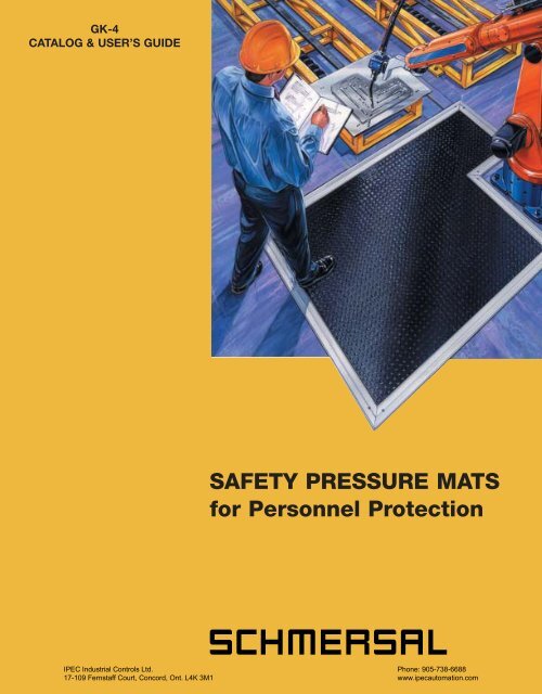
SAFETY PRESSURE MATS for Personnel Protection
SAFETY PRESSURE MATS for Personnel Protection
SAFETY PRESSURE MATS for Personnel Protection
Create successful ePaper yourself
Turn your PDF publications into a flip-book with our unique Google optimized e-Paper software.
GK-4<br />
CATALOG & USER’S GUIDE<br />
<strong>SAFETY</strong> <strong>PRESSURE</strong> <strong>MATS</strong><br />
<strong>for</strong> <strong>Personnel</strong> <strong>Protection</strong><br />
IPEC Industrial Controls Ltd.<br />
17-109 Fernstaff Court, Concord, Ont. L4K 3M1<br />
Phone: 905-738-6688<br />
www.ipecautomation.com
Series SMS 3 Safety Pressure Mats<br />
Description & Operation<br />
The maintenance-free series SMS 3 safety mat system is designed to safeguard<br />
personnel when entering a hazardous area around dangerous machinery. A<br />
person’s presence is detected upon their stepping/walking on the mat. The<br />
interconnected safety controller (such as the AZR 31 R2, AZR 31 T2, or<br />
AZR 11 RT2) continuously monitors the integrity of the safety mat system, sending<br />
a “stop” signal to the machinery in the event of a system fault or pressure mat<br />
actuation.<br />
When properly installed with the active edge profiles, a 100% mat actuation area<br />
is achieved… thus complying with the stringent requirements of EN 954-1 safety<br />
category 3.<br />
Construction & Principle of Operation<br />
The series SMS 3 safety mat consists of two electrodes (steel plates)<br />
separated by an internal layer of compressible elastomeric insulating strips.<br />
The insulating strips are capped by a conductive u-shaped strip whose<br />
edges overhang the compressible insulator.<br />
Upon the application of pressure (e.g. walking/stepping on the mat), the<br />
insulating strips compress allowing the conductive strip to close the<br />
normally-open circuit between the steel electrodes. This closure signal is<br />
detected by the system’s safety controller whose safety output(s) sends a<br />
“stop” signal to the machinery being approached.<br />
Typical Applications<br />
• Robotic work cells<br />
• Laser welding/cutting equipment<br />
• Packaging machinery<br />
• Woodworking machinery<br />
• Textile machinery<br />
• Palletizing/stacking/shrink wrapping systems<br />
• Paper converting machinery<br />
• Material handling equipment<br />
• Tube-bending equipment<br />
• Assembly machinery<br />
• Stamping equipment<br />
• Printing machinery<br />
IPEC Industrial Controls Ltd.<br />
2<br />
17-109 Fernstaff Court, Concord, Ont. L4K 3M1<br />
Phone: 905-738-6688<br />
www.ipecautomation.com
Mat Anatomy<br />
1 Non-slip safety mat surface<br />
2 Upper electrode (24-gauge steel plate, hardened <strong>for</strong> optimum per<strong>for</strong>mance & durability)<br />
3 Edge spacer<br />
4 Conductive (u-shaped) contact strips<br />
5 Compressible, elastomeric insulating strips<br />
6 Lower electrode (24-gauge steel plate, hardened <strong>for</strong> optimum per<strong>for</strong>mance & durability)<br />
7 Safety mat bottom surface<br />
Features & Benefits<br />
• 100% active mat area… active edge trim and insulating strip-contact design ensure actuation over entire<br />
mat surface<br />
• High chemical resistance… mat material is tolerant to most acids, alcohols, aldehydes, caustics, solvents<br />
and oils found in an industrial environment<br />
• Non-slip surface profile… unique surface geometry designed to enhance traction and minimize slippage<br />
• Meets safety category 3 requirements of EN 954-1… suitable <strong>for</strong> most industrial applications<br />
• Modular design… permits protection over a diversity of hazardous area shapes/sizes<br />
• Easy-to-install… simple 4-wire connection (without need of a terminal resistor or additional base plate)<br />
• Integral 6m cable… satisfies wiring requirements <strong>for</strong> a wide variety of applications<br />
• Rugged IP67 design… with mechanical life expectancy of more than 5 million actuations<br />
• Fully CE-compliant… third-party certified to EN1760-1<br />
• Extended warranty… mats are warranteed <strong>for</strong> 3 years from date of shipment<br />
IPEC Industrial Controls Ltd.<br />
17-109 Fernstaff Court, Concord, Ont. L4K 3M1<br />
Phone: 905-738-6688<br />
www.ipecautomation.com<br />
3
Active Edge (SMS P-100)<br />
Schmersal’s SMS P-100 active edge is an integral part of<br />
the SMS Series safety category 3 safety mat system. This<br />
unique, patented design ensures mat actuation when<br />
stepping on the edge profile… thus guaranteeing a 100%<br />
active mat area in single and multiple-mat installations.<br />
It is important to recognize that the active edge<br />
profile/trim plates are an integral component of the<br />
SMS 3 safety mat system. Consequently they must<br />
not be replaced by other components.<br />
4,8<br />
2,9<br />
4,8<br />
2,9<br />
32<br />
84<br />
4<br />
9,2<br />
4<br />
IPEC Industrial Controls Ltd.<br />
17-109 Fernstaff Court, Concord, Ont. L4K 3M1<br />
Phone: 905-738-6688<br />
www.ipecautomation.com
Custom Shapes & Sizes<br />
Schmersal’s CE-compliant safety mats can be custom made<br />
in a wide range of shapes and sizes to suit your application<br />
requirements. We would be pleased to prepare a proposal and<br />
quotation <strong>for</strong> a cost-effective solution that satisfies your unique<br />
needs. Please call should you have a specific application challenge.<br />
(Please see Page 6 <strong>for</strong> ordering in<strong>for</strong>mation.)<br />
Specification<br />
Technical Data<br />
Con<strong>for</strong>mance to Standards EN 1760-1<br />
Degree of Ingress <strong>Protection</strong> IP 67 per IEC 60529<br />
Response Time ≤ 30 ms (Single mat only)<br />
Mechanical Life Expectancy > 5 million operations<br />
Maximum Load<br />
2000 N/cm 2 (2,900 lbs/sq. in)<br />
Active Area<br />
100% Active Area (with SMS P-100 “Active Edge”)<br />
Surface Material Mat: Vinyl Active Edge: Aluminum<br />
Mat Thickness<br />
12 mm (0.5 in)<br />
Mat Weight<br />
18 kg/m 2 (3.7 lbs/sq. ft)<br />
Standard Cable Length<br />
6 meters (19.7 ft)<br />
(Other lengths available.<br />
Please consult factory.)<br />
Ambient Operating<br />
Temperature Range +5°C to +50°C (+41°F to +122°F)<br />
Storage Temperature<br />
-20°C to +50°C (-4°F to +122°F)<br />
Warranty Period<br />
3 Years (from date of shipment)<br />
Agency Approvals<br />
CE-Compliant<br />
Chemical Resistance<br />
Water: Excellent<br />
(Please consult factory <strong>for</strong><br />
other chemical compatibility)<br />
Mineral Acids: Good – Excellent<br />
Organic Acids: Good – Excellent<br />
Alcohols: Good<br />
Aldehydes: Good – Excellent<br />
Caustics: Good – Excellent<br />
Petroleum Solvents: Fair – Good<br />
Oils: Good<br />
IPEC Industrial Controls Ltd.<br />
17-109 Fernstaff Court, Concord, Ont. L4K 3M1<br />
Phone: 905-738-6688<br />
www.ipecautomation.com<br />
5
Optional Features<br />
“Tru-Grit” Surface Finish…<br />
Provides added traction in<br />
wet/oily applications<br />
SCHMERSAL’s “Tru-Grit” surface finish<br />
provides added traction in applications<br />
where mats are subject to liquids, oils<br />
and/or greases. These mats feature a<br />
non-skid, non-wearing granular material<br />
tightly bonded to the vinyl surface and<br />
capable of withstanding heavy pedestrian<br />
and vehicular traffic.<br />
Standard Safety Mat & Trim Kit Ordering In<strong>for</strong>mation<br />
Standard Sizes<br />
(Other sizes and<br />
non-rectangular<br />
shapes available.<br />
Please consult factory.)<br />
Model<br />
Length x Width<br />
(Mat only, without trim kit)*<br />
“Active Edge”<br />
Trim Kit<br />
(Must be ordered<br />
separately)*<br />
SMS 3 25-25 250 mm x 250 mm SMS P 100-25-25<br />
SMS 3 25-50 250 mm x 500 mm SMS P 100-25-50<br />
SMS 3 25-100 250 mm x 1000 mm SMS P 100-25-100<br />
SMS 3 50-50 500 mm x 500 mm SMS P 100-50-50<br />
SMS 3 50-100 500 mm x 1000 mm SMS P 100-50-100<br />
SMS 3 50-150 500 mm x 1500 mm SMS P 100-50-150<br />
SMS 3 75-75 750 mm x 750 mm SMS P 100-75-75<br />
SMS 3 75-100 750 mm x 1000 mm SMS P 100-75-100<br />
SMS 3 75-150 750 mm x 1500 mm SMS P 100-75-150<br />
SMS 3 100-100 1000 mm x 1000 mm SMS P 100-100-100<br />
SMS 3 100-150 1000 mm x 1500 mm SMS P 100-100-150<br />
SMS 3 120-120 1200 mm x 1200 mm SMS P 100-120-120<br />
SMS 3 120-150 1200 mm x 1500 mm SMS P 100-120-150<br />
*”Active Edge” trim kits are supplied mitered, drilled and countersunk. Each is supplied with stainless-steel<br />
mounting hardware. The user/installer is responsible <strong>for</strong> cutting a notch at their desired wire exit point at time<br />
of installation. Active Edge trim adds 50 mm to installed dimension on each side. For example, a 250 mm x 250<br />
mm mat with Active Edge trim all around would have installed dimensions of 350 mm x 350 mm.<br />
Note: Safety mats and trim kits must be ordered with a compatible safety controller.<br />
(Please see Page 7 <strong>for</strong> available safety controller models.)<br />
Please advise factory if other than standard 6m cable is desired.<br />
6<br />
IPEC Industrial Controls Ltd.<br />
17-109 Fernstaff Court, Concord, Ont. L4K 3M1<br />
Phone: 905-738-6688<br />
www.ipecautomation.com
Compatible Safety Controllers (Safety Relay Modules)<br />
The SMS 3 safety mat system includes a choice of three compatible<br />
safety controllers… one of which is required <strong>for</strong> each installation.<br />
These choices are summarized in the chart below with complete technical specifications shown on Page 8.<br />
Type Number of Available Safety Controller<br />
Model Number Reset Safety Outputs Signaling Input Voltage<br />
(See Note 1)<br />
Output<br />
AZR3IT2-24VAC Automatic 3 1 N.C. (Voltage-free) 24VAC<br />
AZR3IT2-24VDC Automatic 3 1 N.C. (Voltage-free) 24VDC<br />
AZR3IT2-110VAC Automatic 3 1 N.C. (Voltage-free) 110VAC<br />
AZR3IR2-24VAC Manual 3 1 N.C. (Voltage-free) 24VAC<br />
AZR3IR2-24VDC Manual 3 1 N.C. (Voltage-free) 24VDC<br />
AZR3IR2-110VAC Manual 3 1 N.C. (Voltage-free) 110VAC<br />
AZR11RT2-24VDC Automatic 1 1 N.O. (PNP-output) 24VDC<br />
(user selectable)<br />
Note 1: Manual reset units require the presence of a discrete “trailing edge” signal (24V to 0V) to activate<br />
(reset) the safety outputs. A reset button must be provided.<br />
Automatic reset units do not require a reset signal. These units automatically re-activate (reset) the<br />
safety outputs when pressure is removed from the mat and no other safety circuit faults exist. A<br />
discrete reset button may be used <strong>for</strong> increased safety.<br />
Each of these DIN-rail mountable safety controllers are designed to monitor the integrity of the SMS 3 safety<br />
mat circuit. In the event of mat actuation or the occurrence of a fault in the circuit, the safety output(s) will be<br />
activated to stop the hazardous machinery. Detectable faults include:<br />
• Open circuit in interconnection wiring<br />
• Short in the interconnection wiring<br />
• Fault in one or more of the controller’s safety relays<br />
• Welded contact in the controlled positive-guided motor contactor or control relay<br />
In addition, each unit features LED system status indicators to aid in installation and trouble shooting.<br />
IPEC Industrial Controls Ltd.<br />
17-109 Fernstaff Court, Concord, Ont. L4K 3M1<br />
Phone: 905-738-6688<br />
www.ipecautomation.com<br />
7
Series SMS 3 Safety Controller Technical Specifications<br />
Specification<br />
Con<strong>for</strong>mance to Standards<br />
Housing Material<br />
Mounting Arrangement<br />
Housing Dimensions<br />
Degree of Ingress <strong>Protection</strong><br />
Operating Voltage<br />
Technical Data<br />
EN 60204-1, IEC60204-1, EN954-1, EN292-1,<br />
EN292-2, DIN VDE 0110-1, VDE 0113 Part 1<br />
Polycarbonate<br />
DIN-rail mounting according to<br />
DIN EN 50022<br />
AZR31: 73.2mm x 45mm x 121mm<br />
AZR11: 82mm x 22.5mm x 98.8mm<br />
Terminals: IP20<br />
Housing: IP40<br />
(per IEC 60529)<br />
24VAC ± 15% (AZR31)<br />
24VDC ± 15% (AZR31 & AZR11)<br />
110VAC ± 15% (AZR31)<br />
230VAC ± 15% (AZR31… available on request)<br />
Power Consumption AZR31:
Appendix:<br />
Series SMS 3 Safety Mat System Installation & Maintenance Instructions<br />
Table of Contents<br />
Topic<br />
1. Safety Mat System SMS 3 10<br />
1.1. General<br />
1.2. Typical Applications<br />
1.3. Safety Mat System<br />
2. General Safety Instructions 11<br />
2.1. Proper Use<br />
2.2. Safety Distance Calculations<br />
3. Items Provided When Ordering Safety Mat System 12<br />
4. Mat Design 12<br />
5. Installation 13<br />
5.1. Preparation<br />
5.1.1. Mat Positioning Plan<br />
5.1.2. Preparation of Floor<br />
5.2.1. Proper Handling of Tactile Mats<br />
5.2.2. Placing the Tactile Mats<br />
5.2.3. Fitting the Active Edges<br />
6. Electrical Connection 15<br />
6.1. Connection of Mats<br />
6.2. Connecting Multiple Mats<br />
6.3. Troubleshooting<br />
7. Initial Inspection 16<br />
7.1. Testing<br />
7.1.1. Function of Safety Controller Modules<br />
7.1.2. Function of Tactile Mats & Active Edges<br />
7.1.3. Safety Distance<br />
7.1.4. Environmental Conditions<br />
7.1.5. Active Edges<br />
7.1.6. Bypassing of Tactile Mats<br />
7.1.7. Loss of Power<br />
8. Periodic Inspections 16<br />
9. Technical Specifications 17<br />
10. Mat Cleaning & Maintenance 18<br />
10.1. Recommended Cleaners<br />
10.2. Pressure Washing/Steam Cleaning<br />
10.3. Brush Cleaning<br />
10.4. Recommended Practices During Cleaning<br />
11. Declaration of Con<strong>for</strong>mity 19<br />
Page<br />
Consideration of Applicable Standards & Other System Components<br />
The contents of these installation and maintenance instructions are subject to technical modifications as a<br />
result of the continuous development of Schmersal products and services. Schmersal is not responsible<br />
<strong>for</strong> any typographical errors.<br />
In addition to the instructions given in this mounting and wiring instructions, it is important to consider the<br />
appropriate national and international standards and regulations.<br />
Liability exclusion in case of inappropriate use<br />
Schmersal is not liable <strong>for</strong> damages caused by the improper use of the equipment.<br />
The accurate knowledge of the contents of this mounting and wiring instruction is fundamental <strong>for</strong><br />
appropriate use. In particular, the contained remarks and safety remarks must be considered.<br />
In the event the product is used in combination with other components such as controls, PLC’s or<br />
sensors, the mounting and wiring instructions <strong>for</strong> those components must also be considered.<br />
IPEC Industrial Controls Ltd.<br />
17-109 Fernstaff Court, Concord, Ont. L4K 3M1<br />
Phone: 905-738-6688<br />
www.ipecautomation.com<br />
9
1. Safety Mat SMS 3<br />
1.1. General<br />
Series SMS 3 Safety mats are used<br />
<strong>for</strong> the safeguarding of hazardous<br />
areas around dangerous machines.<br />
A safety mat is a pressure sensitive<br />
safety device in accordance with<br />
European standard EN 1760-1. The<br />
safety mat system fulfills the<br />
requirements of a safety category 3<br />
Safety Device<br />
(EN 954-1).<br />
Various safety controllers (monitoring<br />
modules) are available. These include<br />
the AZR 31 R2 with manual reset,<br />
AZR 31 T2 with automatic reset…<br />
with three enabling paths each, and<br />
AZR 11 RT2 with selectable manual or<br />
automatic reset and one enabling<br />
path. The safety monitoring module is<br />
an essential element of the safety mat<br />
system.<br />
IMPORTANT INSTALLATION NOTE:<br />
The EC type-examination is invalid<br />
if alternatives to the above listed<br />
Schmersal safety controller<br />
modules are used.<br />
1.2 Typical applications<br />
There are many types of applications.<br />
Common applications include:<br />
• Robotic work cells<br />
• Laser welding/cutting equipment<br />
• Packaging machinery<br />
• Woodworking machinery<br />
• Textile machinery<br />
• Palletizing/stacking/shrink<br />
wrapping systems<br />
• Paper converting machinery<br />
• Material handling equipment<br />
• Tube-bending equipment<br />
• Assembly machinery<br />
• Stamping equipment<br />
1.3. Safety mat system:<br />
tactile mat, active<br />
edge, and safety<br />
controller module<br />
The complete safety mat system<br />
consists of tactile mat(s) with active<br />
edges and one Series AZR safety<br />
controller module.<br />
SMS 3 Tactile mat with active edges<br />
Safety module AZR 31 R2 or<br />
Safety module AZR 31 T2 or<br />
Safety module AZR 11 RT2<br />
IMPORTANT INSTALLATION NOTE:<br />
The tactile mat cannot be used<br />
without a safety module and in all<br />
installations must be connected to<br />
one of the above shown safety<br />
controller modules.The active<br />
edge profiles are considered<br />
components of the safety mat<br />
and may not be replaced by<br />
other products.<br />
Actuating the safety mat opens the<br />
safety enabling path(s) and initiates an<br />
immediate machine stop signal. In<br />
order to assure proper safeguarding<br />
by the safety mat system, the control<br />
system of the safeguarded machine<br />
must allow an immediate stop of the<br />
dangerous motion at any time.<br />
The tactile mat can also be used <strong>for</strong><br />
object detection, especially <strong>for</strong><br />
detection of vehicles.<br />
The safety mat should not be used <strong>for</strong><br />
the protection of children in<br />
hazardous areas.<br />
10<br />
IPEC Industrial Controls Ltd.<br />
17-109 Fernstaff Court, Concord, Ont. L4K 3M1<br />
Fig. 1: Example of using safety mats at a stamping machine<br />
Phone: 905-738-6688<br />
www.ipecautomation.com
2. General Safety Instructions<br />
2.1. Proper Use<br />
The Series SMS 3 safety mat system<br />
is a pressure sensitive safety device<br />
used <strong>for</strong> the safeguarding of<br />
hazardous areas around machines.<br />
The tactile mat should be placed on a<br />
flat smooth surface around the<br />
machine. When designing machine<br />
safeguarding, approach speed, safety<br />
distance and the possibility of<br />
stepping behind or bypassing of the<br />
safety device must be considered.<br />
The operator must not be able to<br />
reach the nearest danger point be<strong>for</strong>e<br />
the machine has stopped. This is<br />
accomplished by the proper<br />
calculation of the safety distance and<br />
installation of the tactile mat(s). When<br />
choosing the safety device, the<br />
appropriate regulations have to be<br />
considered. Safety categories in<br />
accordance with EN 954-1 <strong>for</strong><br />
pressure sensitive mats (safety mats)<br />
on machines are stated in type C<br />
standards.<br />
We recommend the operator be given<br />
a general introduction to the features<br />
and function of the safety mat and the<br />
protected zone. Correct installation,<br />
inspecting, testing and periodic<br />
inspection are required <strong>for</strong> proper use<br />
of the device.<br />
IMPORTANT INSTALLATION NOTE:<br />
When designing a machine or<br />
installing a safety mat system, the<br />
safety requirements of the<br />
machinery directive (98/37/EC)<br />
and their appendices and<br />
amendments, as well as the<br />
relevant safety standards, must<br />
be respected.<br />
2.2. Safety Distance<br />
Calculations<br />
The correct positioning of the tactile<br />
mats with regard to the nearest<br />
danger point is mainly dependent on<br />
the stopping per<strong>for</strong>mance of the<br />
machine and the assumed approach<br />
speed of the operator. The standard<br />
EN 999 (Safety of Machinery,<br />
Hand/Arm-Speed) provides a <strong>for</strong>mula<br />
<strong>for</strong> calculating the appropriate safety<br />
distance.<br />
Safety distance <strong>for</strong>mula:<br />
S = K x (T1 +T2) + (1200 – 0.4 H)<br />
S is the minimum distance in<br />
millimeters, from the danger zone<br />
to the detection point, line, plane<br />
or zone<br />
K is a parameter in millimeters per<br />
second, derived from data on<br />
approach speeds of the body or<br />
parts of the body<br />
H distance above the floor (i.e.<br />
plat<strong>for</strong>m) in mm (<strong>for</strong> safety mats<br />
this term is usually 0 mm)<br />
T1 is the maximum time between the<br />
actuation of the sensing function<br />
(tactile mat) and the switching off<br />
of the safety enabling outputs (e.g.<br />
the output signal switching device<br />
OSSD of the safety module)<br />
(response time see “Technical<br />
specifications”, Section 9)<br />
T2 is the response time of the<br />
machine, i.e. the time required to<br />
stop the machine or remove the<br />
risks after receiving the signal from<br />
the AZR safety controller<br />
The safety distance can generally be<br />
calculated as follows:<br />
S = 1600 mm/s x (T1 +T2) + 1200 mm<br />
Safety Distance<br />
Calculation Example:<br />
Calculate the safety distance <strong>for</strong> a<br />
machine <strong>for</strong> which the stop time is<br />
117.5 ms, the response time of the<br />
tactile mat and safety module is<br />
70 ms; the tactile mats are at floor<br />
level.<br />
S = 1600 mm/s x (0,07 s + 0,1175 s)<br />
+ 1200 mm<br />
S = 1600 mm/s x (0,1875 s)<br />
+ 1200 mm<br />
S = 300 mm + 1200 mm<br />
S = 1500 mm<br />
IPEC Industrial Controls Ltd.<br />
17-109 Fernstaff Court, Concord, Ont. L4K 3M1<br />
Phone: 905-738-6688<br />
www.ipecautomation.com<br />
11
3. Items Provided (when ordering an SMS 3 Safety Mat)<br />
The following items are provided<br />
when ordering your safety mat.<br />
• Tactile mat incl. 6 m cable<br />
• Mounting and wiring instructions<br />
IMPORTANT INSTALLATION NOTE:<br />
Active Edge trim kits and Series<br />
AZR safety controllers must be<br />
ordered separately.<br />
4. Mat Design<br />
1 Non-slip surface<br />
2 Upper electrode (steel plate)<br />
3 Edge spacer<br />
4 Conductive contact strips<br />
5 Compressible insulating strips<br />
6 Lower electrode (steel plate)<br />
7 Safety mat bottom surface<br />
The tactile mat consists of electrodes (steel<br />
plates) which are separated from each other.<br />
These are held apart using insulation strips.<br />
Electrode strips located between the two steel<br />
plates cause an electrical short circuit when the<br />
pressure sensitive mat (tactile mat) is actuated.<br />
Fig. 2: Design of the tactile mat<br />
Fig. 3: Function of the tactile mat<br />
12<br />
IPEC Industrial Controls Ltd.<br />
17-109 Fernstaff Court, Concord, Ont. L4K 3M1<br />
Phone: 905-738-6688<br />
www.ipecautomation.com
5. Installation<br />
5.1. Preparation<br />
5.1.1. Mat Positioning<br />
Plan<br />
Develop a plan <strong>for</strong> positioning the<br />
tactile mats in the dangerous area.<br />
5.1.2. Preparation of Floor<br />
For the installation of the tactile mat<br />
the floor should be smooth, dry and<br />
free of debris. The possible collection<br />
of fluids should be prevented.<br />
5.2.1. Proper Handling<br />
of Tactile Mats<br />
To carry a tactile mat grasp the long<br />
edges. Place cable on the mat when<br />
carrying. Large mats should be<br />
handled by two people. Store tactile<br />
mats flat. Do not bend! Do not<br />
damage mats by drilling, nailing or<br />
cutting.<br />
5.2.2. Placing the<br />
Tactile Mat(s)<br />
Place the tactile mat(s) at their<br />
approximate final position leaving a<br />
space of approximately 15 mm<br />
between the tactile mats. Pay<br />
particular attention to the cable<br />
locations.<br />
If multiple tactile mats are to be<br />
connected to safeguard larger areas,<br />
a separate junction box <strong>for</strong> the<br />
electrical connections must be used.<br />
There<strong>for</strong>e route the cables to one side<br />
of the tactile mats.<br />
Make sure that the cables are not<br />
stretched, kinked or pinched.<br />
Fig. 4: Mounting example of the tactile mat<br />
IPEC Industrial Controls Ltd.<br />
17-109 Fernstaff Court, Concord, Ont. L4K 3M1<br />
Phone: 905-738-6688<br />
www.ipecautomation.com<br />
13
5. Installation<br />
5.2.3. Fitting the Active Edge<br />
Place the active edge profiles across the<br />
space between tactile mats and along the<br />
mat edges. Route the mat cables and mark<br />
the active edge profile where the cable will<br />
exit. Notch the active edge profile, if needed<br />
<strong>for</strong> the cable exits. Remove burrs and sharp<br />
edges to avoid damaging the cable(s).<br />
Use the active edge profile as a template.<br />
Start the anchor holes on the floor by<br />
drilling (depth approximately 5 mm). Drill<br />
end holes first.<br />
Remove the active edge profiles and drill the<br />
anchor holes to a depth of about 25 mm.<br />
Insert the screw anchors into holes.<br />
Clean the floor area of the active edge profile<br />
and reposition the active edge profiles.<br />
Moisten the screws with glue. Insert and<br />
tighten screws into anchors until the screw<br />
head is about 1 mm below the surface of the<br />
active edge profile. Be careful not to damage<br />
mat cables.<br />
Fig. 5: Active edge profile<br />
4,8<br />
2,9<br />
32<br />
84<br />
Fig. 6: Dimensions of active edge profile (in mm)<br />
4,8<br />
4<br />
2,9<br />
9,2<br />
IMPORTANT INSTALLATION NOTE:<br />
When installing mat edges with the<br />
active edge profiles, please be careful<br />
not to activate the tactile mats by<br />
tightening the screws too much.<br />
Fastening the Optional<br />
Edge Covers<br />
Position the active edge profiles so that the<br />
edge covers overlap a min. of 10 mm and a<br />
max. of 25 mm (see Fig. 7).<br />
Place the edge cover over the positioned<br />
active edge profiles. Drill and fasten the<br />
edge cover as described above.<br />
Fig. 7: Optional edge cover<br />
15,8<br />
Fig. 8: Dimensions of the<br />
edge cover<br />
95,2<br />
79,4<br />
6,3<br />
43,2<br />
8,4<br />
14<br />
IPEC Industrial Controls Ltd.<br />
17-109 Fernstaff Court, Concord, Ont. L4K 3M1<br />
Phone: 905-738-6688<br />
www.ipecautomation.com
6. Electrical Connection<br />
6.1. Connection of Mats<br />
The safety mat circuit is connected to<br />
the safety module. Each tactile mat<br />
has a 4 wire color-coded (2 black, 2<br />
white) cable. Connect the wires of the<br />
tactile mat as follows.<br />
Connection example AZR 31:<br />
S13 = White (2)<br />
S14 = White (4)<br />
S23 = Black (1)<br />
S24 = Black (3)<br />
Connection example AZR 11:<br />
S13 = White (2)<br />
S14 = White (4)<br />
S23 = Black (1)<br />
0 V = Black (3)<br />
6.2. Connecting Multiple<br />
Tactile Mats<br />
If multiple tactile mats are to be<br />
connected to safeguard larger areas,<br />
a separate junction box <strong>for</strong> the<br />
electrical connections shall be used.<br />
This junction box should be elevated<br />
off the floor, within reach of each mat<br />
cable and have a minimum enclosure<br />
rating of IP 54. The tactile mats must<br />
be connected in series according to<br />
figures 9 and 10.<br />
IMPORTANT INSTALLATION NOTE:<br />
Please consult factory <strong>for</strong> the<br />
maximum number of mats that<br />
may be connected to a given<br />
safety controller.<br />
#1<br />
1 2 3 4<br />
0V<br />
S13<br />
#1<br />
1 2 3 4<br />
S23 S13<br />
3<br />
3<br />
4<br />
#2<br />
4<br />
#2<br />
1<br />
1<br />
1<br />
1<br />
#3<br />
2<br />
2<br />
#3<br />
2<br />
2<br />
3<br />
3<br />
4<br />
S24S14<br />
Fig. 9: Wiring example of the of the<br />
AZR 31 in connection with multiple<br />
tactile mats.<br />
4<br />
S24S14<br />
Fig. 10: Wiring example of the<br />
AZR 11 in connection with multiple<br />
tactile mats.<br />
6.3. Troubleshooting<br />
Green LEDs show operational<br />
conditions of the Series AZR<br />
safety modules.<br />
LEDs AZR 31:<br />
ON: Operating voltage<br />
IN A: Channel A<br />
IN B: Channel B<br />
OUT: Authorized operation<br />
LEDs AZR 11:<br />
ON: Operating voltage<br />
IN: Inputs<br />
LED ON OFF<br />
ON Operating voltage O.K. Operating voltage missing or<br />
defect in internal current<br />
supply<br />
IN A Input S13 – S14 closed Input S13 – S14<br />
opened or wire break<br />
IN B Input S23 – S24 closed Input S23 – S24 opened or<br />
wire break<br />
OUT The two internal relays are One of the two inputs IN A or<br />
connected through, when<br />
IN B is not actuated,<br />
IN A and IN B are actuated or feedback input<br />
and feedback input is is not closed (AZR 31 T2)<br />
closed (AZR 31 T2) or closed or closed and not<br />
and re-opened (AZR 31 R2) re-opened (AZR 31 R2)<br />
IMPORTANT INSTALLATION NOTE: Switch off power supply be<strong>for</strong>e you<br />
connect the safety controller module. Never connect with power on.<br />
For wiring examples and more in<strong>for</strong>mation see mounting and wiring instructions of<br />
the safety controller modules AZR 31 R2, AZR 31 T2 or AZR 11 RT2.<br />
IPEC Industrial Controls Ltd.<br />
17-109 Fernstaff Court, Concord, Ont. L4K 3M1<br />
Phone: 905-738-6688<br />
www.ipecautomation.com<br />
15
7. Initial Inspection<br />
Check function of the safety device<br />
carefully be<strong>for</strong>e putting the machine<br />
into operation.<br />
The check should be per<strong>for</strong>med by a<br />
person who is familiar with the details<br />
of the mounting and wiring<br />
instructions as well as with the<br />
functions of the machine and safety<br />
device.<br />
IMPORTANT INSTALLATION NOTE:<br />
The overall safety of the machine<br />
is dependent upon how the<br />
enabling path(s) of the AZR safety<br />
controller modules are connected<br />
to the safety circuit. The whole<br />
safety control circuit should be<br />
designed according to the<br />
requirements of the relevant<br />
safety categories in EN 954-1.<br />
7.1. Testing<br />
7.1.1. Function of the<br />
Safety Controller<br />
Modules<br />
Switch on the power supply to the<br />
safety controller module. The green<br />
LEDs on the safety module indicate<br />
that the output relays are energized,<br />
which allows the machine to start (if<br />
fault see troubleshooting, chapter 6.3.).<br />
7.1.2. Function of Tactile<br />
Mats, Active Edge<br />
Profiles (and Edge<br />
Covers)<br />
Please test each active component of<br />
the safety device… mat, active edge<br />
profiles and (if used) edge covers…<br />
by stepping on them. This will<br />
deactivate the safety relays and cause<br />
the LEDs to turn off.<br />
7.1.3. Safety Distance<br />
Review the correct safety distance<br />
between the first edge of mat and the<br />
nearest danger point (see section 2.2.).<br />
7.1.4. Environmental<br />
Conditions<br />
Check that environmental conditions<br />
are suitable <strong>for</strong> the use of the tactile<br />
mat (e.g. no chemicals are present<br />
which will compromise the<br />
per<strong>for</strong>mance of the mat).<br />
7.1.5. Active Edges<br />
Make sure that the active edge<br />
profiles are fastened securely and do<br />
not provide a trip hazard.<br />
7.1.6. Bypassing of<br />
Tactile Mats<br />
Make sure that no one can bypass or<br />
step over the tactile mats. Make sure<br />
that no one can stand in the danger<br />
area without being detected.<br />
7.1.7. Loss of power<br />
After switching off the power supply<br />
to the safety module the machine<br />
must stop automatically. An<br />
automatic machine restart must<br />
be prevented with a restart<br />
interlock in the machine control<br />
circuit.<br />
8. Periodic Inspections<br />
In addition to the initial commissioning<br />
check be<strong>for</strong>e putting the machine<br />
into operation, we also recommend<br />
the following inspections:<br />
• A simple daily functional test of<br />
the safety device<br />
• A complete inspection every six<br />
months of all components of the<br />
safety device (wear, damage,<br />
manipulation) and mechanical<br />
components (overall stopping<br />
per<strong>for</strong>mance) by a safety trained<br />
person.<br />
The tactile mat is maintenance free.<br />
When properly used it will provide<br />
effective safeguarding. If a replacement<br />
is required, it will be recognized<br />
during daily or six month inspection.<br />
For the name or identification number<br />
of the mat see mat surface.<br />
IMPORTANT INSTALLATION<br />
NOTE: If any faults are noticed<br />
which affect safety, the machine<br />
must be put out of operation until<br />
the safety function is repaired.<br />
16<br />
IPEC Industrial Controls Ltd.<br />
17-109 Fernstaff Court, Concord, Ont. L4K 3M1<br />
Phone: 905-738-6688<br />
www.ipecautomation.com
9. SMS 3 Safety Pressure Mat Technical Specifications<br />
Con<strong>for</strong>mance to Standards:<br />
EN 1760-1<br />
Degree of Ingress <strong>Protection</strong>:<br />
IP 67 per IEC 60529<br />
Response Time:<br />
≤ 30 ms (Single mat only)<br />
Mechanical Life Expectancy:<br />
> 5 million operations<br />
Maximum Load:<br />
2000 N/cm 2 (2,900 lbs/sq. in)<br />
Active Area:<br />
100% Active Area<br />
(with SMS P-100 active edge)<br />
Material:<br />
Mat: Vinyl; Active Edge: Aluminum<br />
Mat Thickness:<br />
12 mm (0.5 in)<br />
Mat Weight:<br />
18 kg/m 2 (3.7 lbs/sq. ft)<br />
Standard Cable Length:<br />
6 meters (19.7 ft)<br />
(Other lengths available. Please<br />
consult factory.)<br />
Ambient Operating<br />
Temperature Range:<br />
+5°C to +50°C<br />
(+41°F to +122°F)<br />
Storage Temperature:<br />
-20°C to +50°C<br />
(-4°F to +122°F)<br />
Standard Sizes:<br />
Model<br />
Length x Width<br />
(Mat only, without trim kit)*<br />
“Active Edge” Trim Kit<br />
(Must be ordered<br />
separately)*<br />
SMS 3 25-25 250 mm x 250 mm SMS P 100-25-25<br />
SMS 3 25-50 250 mm x 500 mm SMS P 100-25-50<br />
SMS 3 25-100 250 mm x 1000 mm SMS P 100-25-100<br />
SMS 3 50-50 500 mm x 500 mm SMS P 100-50-50<br />
SMS 3 50-100 500 mm x 1000 mm SMS P 100-50-100<br />
SMS 3 50-150 500 mm x 1500 mm SMS P 100-50-150<br />
SMS 3 75-75 750 mm x 750 mm SMS P 100-75-75<br />
SMS 3 75-100 750 mm x 1000 mm SMS P 100-75-100<br />
SMS 3 75-150 750 mm x 1500 mm SMS P 100-75-150<br />
SMS 3 100-100 1000 mm x 1000 mm SMS P 100-100-100<br />
SMS 3 100-150 1000 mm x 1500 mm SMS P 100-100-150<br />
SMS 3 120-120 1200 mm x 1200 mm SMS P 100-120-120<br />
SMS 3 120-150 1200 mm x 1500 mm SMS P 100-120-150<br />
*”Active Edge” trim kits are supplied mitered, drilled and countersunk. Each is<br />
supplied with stainless-steel mounting hardware. The user/installer is<br />
responsible <strong>for</strong> cutting a notch at their desired wire exit point at time of<br />
installation. Active Edge trim adds 50 mm to installed dimension on each side.<br />
For example, a 250 mm x 250 mm mat with Active Edge trim all around would<br />
have installed dimensions of 350 mm x 350 mm.<br />
(Other sizes and non-rectangular shapes available. Please consult factory.)<br />
Note: SMS 3 safety mats and trim kits must be ordered with a compatible safety<br />
controller module (Please see Page 7).<br />
Warranty Period:<br />
3 Years (from date of shipment)<br />
Agency Approvals:<br />
CE-Compliant<br />
Chemical Resistance:<br />
Water: Excellent<br />
Mineral Acids: Good – Excellent<br />
Organic Acids: Good – Excellent<br />
Alcohols: Good<br />
Aldehydes: Good – Excellent<br />
Caustics: Good – Excellent<br />
Petroleum Solvents: Fair – Good<br />
Oils: Good<br />
IPEC Industrial Controls Ltd.<br />
17-109 Fernstaff Court, Concord, Ont. L4K 3M1<br />
Phone: 905-738-6688<br />
www.ipecautomation.com<br />
17
10. Mat Cleaning & Maintenance<br />
10.1. Recommended<br />
Cleaners<br />
Most quality industrial cleaners and/or<br />
degreasers are acceptable. However,<br />
cleaning solutions containing<br />
phosphates, chlorine, organic<br />
solvents, or mineral spirits should<br />
not be used.<br />
10.2. Pressure Washing/<br />
Steam Cleaning<br />
Mats may be pressure washed<br />
subject to the following guidelines:<br />
• Any loose debris should be<br />
removed from the mat surface<br />
prior to beginning the pressure<br />
washing process.<br />
• A flat, fan-spray nozzle with a<br />
pattern angle of at least 15<br />
degrees should be used.<br />
• Pressure spray nozzle should be<br />
kept a minimum distance of 12<br />
inches from the mat surface at all<br />
times.<br />
• Spray pressure should not exceed<br />
1,500 psi.<br />
• Spray temperature should not<br />
exceed 190°F (88°C).<br />
• Spray pattern should be kept<br />
moving. Do not concentrate it in<br />
one location.<br />
• Heavily soiled mats should be presoaked<br />
<strong>for</strong> 10–15 minutes in the<br />
cleaning solution, and brushed<br />
with a hand utility brush.<br />
• Upon completion of pressure<br />
washing, mats should be rinsed<br />
with clean water.<br />
10.3. Brush Cleaning<br />
Mats may brush cleaned subject to<br />
the following guidelines:<br />
• Any loose debris should be<br />
removed from the mat surface<br />
prior to beginning the brush<br />
cleaning process.<br />
• Heavily soiled mats may require<br />
pre-soaking <strong>for</strong> 10–15 minutes in<br />
the cleaning solution.<br />
• Use a good utility brush made of<br />
Nylon, Palmyra, Natural Bassine<br />
Tampico or similar material.<br />
• Upon completion of brush<br />
cleaning, mats should be rinsed<br />
with clean water.<br />
10.4. Recommended<br />
Practices During<br />
Cleaning<br />
The following recommended practices<br />
should be respected during mat<br />
cleaning processes:<br />
• Turn off all power to the mat<br />
system prior to beginning the<br />
cleaning process.<br />
• Cover all equipment that may be<br />
susceptible to damage during the<br />
cleaning process.<br />
• Install safety signs indicating wet<br />
floors.<br />
• Install safety barriers as required.<br />
• Wear safety goggles and other<br />
recommended safety apparel<br />
during cleaning.<br />
• Be sure the mats and the<br />
surrounding area are completely<br />
dry be<strong>for</strong>e removing safety signs<br />
and/or barriers, and restoring<br />
electrical power.<br />
18<br />
IPEC Industrial Controls Ltd.<br />
17-109 Fernstaff Court, Concord, Ont. L4K 3M1<br />
Phone: 905-738-6688<br />
www.ipecautomation.com
11. Declaration of Con<strong>for</strong>mity<br />
EG-Kon<strong>for</strong>mitätserklärung<br />
EC Declaration of con<strong>for</strong>mity<br />
Déclaration de con<strong>for</strong>mité CE<br />
Dichiarazione di con<strong>for</strong>mità CEE<br />
Im Sinne der EG-Maschinenrichtlinie 89/392/EWG, Anhang II C erklären wir hiermit, daß das nachfolgend aufgeführte<br />
Sicherheitsbauteil den An<strong>for</strong>derungen der o.g. Richtlinie entspricht.<br />
According to the EC-Machinery directive 89/392/EEC, Annex II C we hereby declare that the following safety<br />
component con<strong>for</strong>ms to the requirements of the above mentioned directive.<br />
Dans l’esprit de la directive CE 89/392/EEC, Annexe II C nous déclarons par la présente que le composant de<br />
sécurité décrit ci-dessous est con<strong>for</strong>me aux exigences de la directive mentionnée.<br />
Nel senso della direttiva macchina CE 89/392, Appendice II C dichiariamo con la presente che il componente di<br />
sicurezza riportato in seguito risponde alle esigenze della nominata direttiva.<br />
Bezeichnung des Sicherheitsbauteils:<br />
SMS 3 + AZR 31 R2 / AZR 31 T2 / AZR 11 RT2<br />
Name of the safety component:<br />
Nom du composant de sécurité:<br />
Nome del componente di sicurezza:<br />
Beschreibung des Sicherheitsbauteils:<br />
Schaltmatte mit Sicherheitsbaustein<br />
Decription of the safety component:<br />
Tactile mat with safety module<br />
Decription du composant de sécurité:<br />
Tapis tactile avec module de sécurité<br />
Descrizione del componente di sicurezza:<br />
Tappeti tàttile con modulo di sicurezza<br />
Einschlägige EG-Richtlinien:<br />
98/37/EG 1989 (Maschinenrichtlinie)<br />
Relevant EC-directives:<br />
73/23/EWG 1973 (Niederspannungsrichtlinie)<br />
Directives CE correspondants:<br />
89/336/EWG 1989 (EMV-Richtlinie)<br />
Corrispondenti dirretive CEE:<br />
Angewandte Normen: EN 1760-1, EN 954-1<br />
Standards applied:<br />
Normes appliquées:<br />
Norme applicate:<br />
Gemeldete Stelle:<br />
Maschinen Technik<br />
Registration office:<br />
SAQ Kontrol AB, Stockholm/Schweden<br />
Office d’enregistration: Europäisch notifizierte Stelle Kenn-Nr.: 409<br />
Ufficio registrazione:<br />
European notified body Id.-No.:<br />
Organisme européen notifié no. d’indice:<br />
Organo europeo notificato no:<br />
Baumusterprüfbescheinigung: Prüfnummer: M539-98<br />
Model test certificate:<br />
Test no.:<br />
Certificat d’examen de type:<br />
No. d’examen:<br />
Certificato di collaudo modello:<br />
Collaudo no.:<br />
Baujahr: 1998<br />
Year of manufacture:<br />
Année de fabrication:<br />
Anno di costruzione:<br />
Anbringung der CE-Kennzeichnung: 1998<br />
Application of the CE-mark:<br />
Application de la marque CE:<br />
Applicazione del marchio CE:<br />
Ort und Datum der Ausstellung: Wuppertal, den 1998-09-28<br />
Place and date of issue:<br />
Lieu et date de l’établissement:<br />
Luogo e data di emissione:<br />
Rechtsverbindliche Unterschrift:<br />
Legally binding signature:<br />
Signature obligatoire:<br />
Heinz Schmersal, Geschäftsführer<br />
Firma del rappresentante legale:<br />
Managing Director<br />
Directeur gérant<br />
Direttore<br />
IPEC Industrial Controls Ltd.<br />
17-109 Fernstaff Court, Concord, Ont. L4K 3M1<br />
Phone: 905-738-6688<br />
www.ipecautomation.com<br />
19
Turning Workplaces Into Safeplaces ®<br />
100 Grasslands Road, Suite 110<br />
Elms<strong>for</strong>d, NY 10523<br />
Telephone: (914) 347-4775<br />
Fax: (914) 347-1567<br />
email: info@schmersalusa.com<br />
schmersalusa.com<br />
IPEC Industrial Controls Ltd.<br />
17-109 Fernstaff Court, Concord, Ont. L4K 3M1<br />
Phone: 905-738-6688<br />
Printed in USA<br />
www.ipecautomation.com


