Flojet Quad II 4105 series - Depco Pump Company
Flojet Quad II 4105 series - Depco Pump Company
Flojet Quad II 4105 series - Depco Pump Company

You also want an ePaper? Increase the reach of your titles
YUMPU automatically turns print PDFs into web optimized ePapers that Google loves.
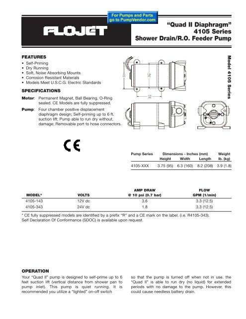
“<strong>Quad</strong> <strong>II</strong> Diaphragm”<br />
Models<strong>4105</strong> Series<br />
Shower Drain/R.O. Feeder <strong>Pump</strong><br />
FEATURES<br />
• Self-Priming<br />
• Dry Running<br />
• Soft, Noise Absorbing Mounts<br />
• Corrosion Resistant Materials<br />
• Models Meet U.S.C.G. Electric Standards<br />
SPECIFICATIONS<br />
Motor: Permanent Magnet, Ball Bearing, O-Ring<br />
sealed. CE Models are fully suppressed.<br />
<strong>Pump</strong>: Four chamber positive displacement<br />
diaphragm design; Self-priming up to 6 ft.<br />
suction lift; <strong>Pump</strong> able to run dry without,<br />
damage; Removable port to hose connectors.<br />
Model <strong>4105</strong> Series<br />
<strong>Pump</strong> Series Dimensions - Inches (mm) Weight<br />
Height Width Length lb. (kg)<br />
<strong>4105</strong>-XXX 3.75 (95) 6.3 (160) 8.2 (208) 3.9 (1.8)<br />
AMP DRAW<br />
FLOW<br />
MODEL* VOLTS @ 10 psi (0.7 bar) GPM (1/min)<br />
<strong>4105</strong>-143 12V dc 3.6 3.3 (12.5)<br />
<strong>4105</strong>-343 24V dc 1.8 3.3 (12.5)<br />
* CE fully suppressed models are identified by a prefix “R” and a CE mark on the label. (i.e. R<strong>4105</strong>-343).<br />
Self Declaration Of Conformance (SDOC) is available upon request.<br />
OPERATION<br />
Your “<strong>Quad</strong> <strong>II</strong>” pump is designed to self-prime up to 6<br />
feet suction lift (vertical distance from shower pan to<br />
pump inlet). This pump is quiet running. It is<br />
recommended you utilize a “lighted” on-off switch<br />
so that the pump is turned off when not in use. the<br />
“<strong>Quad</strong> <strong>II</strong>” is able to run dry (no liquid) for extended<br />
periods with no damage to the pump. However, this<br />
could cause needless battery drain.
INSTALLATION<br />
STEP I<br />
Remove shipping plugs from <strong>Quad</strong> pump ports. Some<br />
water from factory testing may spill out<br />
STEP 2<br />
Install inlet A and discharge, B port connectors. Firmly<br />
push slide clips C forward to lock port connectors in<br />
place.<br />
STEP 3<br />
Slide rubber mounts fully into 4 mounting tracks.<br />
STEP 4<br />
Mount pump vertically, with pump head down or<br />
horizontally in an ible location. If mounting vertically,<br />
motor up, attach motor mounts first then pump head<br />
mounts, while supporting weight of pump.<br />
STEP 5<br />
Use 1/2” I.D. flexible hose (preferably braided or<br />
reinforced). Use hose clamps on the slip-on barb hose<br />
connectors.<br />
STEP 6<br />
Install a 1/2” in line strainer #01740-002 in accessible<br />
location between shower drain pan and pump inlet. This<br />
strainer or equivalent is required for pump warranty to be<br />
valid.<br />
WIRING<br />
STEP I<br />
Use 14 gauge stranded wire to 20’, 12 gauge to 50’,<br />
from power source.<br />
STEP 2<br />
Use a 10-15 amp rated (lighted) on-off switch on the (+)<br />
positive (red) motor lead.<br />
STEP 3<br />
Install 10 amp fuse protection on the positive lead for the<br />
-143 model, use a 7 amp fuse for the -343 model.
TROUBLESHOOTING<br />
WARNING: BEFORE SERVICING PUMP, TURN OFF PUMP AND DRAIN WATER FROM SYSTEM!!<br />
Failure to Prime - Motor operates, but no pump discharge<br />
• Restricted intake or discharge line<br />
• Air leak in intake line<br />
• Debris in pump<br />
• Punctured pump diaphragm (pump leaks)<br />
• Crack in pump housing<br />
Low Flow and Pressure<br />
• Air leak at pump intake<br />
• Accumulation of debris inside pump and plumbing<br />
• Worn pump bearing (excessive noise)<br />
• Punctured pump diaphragm (pump leaks)<br />
• Defective motor<br />
Motor falls to turn on<br />
• Blown fuse<br />
• Loose wiring connection<br />
• <strong>Pump</strong> circuit has no power<br />
• Defective motor<br />
Pulsating Flow<br />
• Restricted pump delivery. Check discharge lines, fittings and<br />
valves for clogging or undersizing.<br />
Quite often when a pump is worn or defective the one failed component has overburdened others. To avoid frequent aggravating<br />
repairs, <strong>Flojet</strong> offers service kit assemblies making repairs as quick and easy as possible.<br />
DISASSEMBLE<br />
Upper Housing<br />
1. Loosen but do not remove four pump head screws and<br />
carefully remove upper housing assembly (1)<br />
2. Inspect check valve (2) for debris<br />
3. Reassemble new upper housing (1)<br />
Check Valve Assembly<br />
Follow step 1<br />
3. Replace check valve (2)<br />
4. Reassemble upper housing (1)<br />
Lower Housing, Diaphragm, Motor<br />
Follow step 1, then slide rubber foot from mounting track.<br />
3. Rotate kmw housing (4) so mounting notch opening on lower<br />
housing exposes set screw which holds bearing housing to<br />
shaft<br />
4. Loosen this set screw by inserting wrench 1/8” Allen wrench<br />
into mounting notch opening. Then, slide lower housing (4) off<br />
motor shaft.<br />
Diaphragm Cont’d<br />
5. Loosen four cam piston screws with Philfips head screw<br />
driver and pull apart cam from inner pistons. (Pistons should<br />
always be replaced when a new diaphragm is installed.)<br />
Motor Cont’d<br />
5. Replace Motor (5)<br />
REASSEMBLE<br />
Motor<br />
1. Reassemble lower housing assembly (4) to motor. (Follow<br />
steps 4 to 10.)<br />
Diaphragm<br />
2. Lower housing is assembled with:<br />
• Flat side of diaphragm and outer pistons facing motor<br />
• Hex stem of inner pistons must be aligned into hex holes in<br />
outer pistons (4).<br />
• Outer pistons must be aligned with alignment slots on cam<br />
assembly making sure screw holes align in cam assembly,<br />
otherwise diaphragm will leak<br />
3. Tighten cam piston screws partially, center piston in<br />
diaphragm, Dien tighten screws securely (18 in. lbs. torque)<br />
Lower Housing<br />
4. Reassemble lower housing assembly (4) to motor.<br />
5. Retighten set screw securely. Set screw head must be<br />
positioned facing motor covering seam (indentation).<br />
(Positioning of this screw is critical to avoid misalignment and<br />
subsequent diaphragm damage.)<br />
Upper Housing, Check Valve<br />
6. Reassemble upper housing (1)<br />
7. Properly seat O-Ring in check valve assembly (2) and check<br />
if ferrules and screen are in place on upper housing (1)<br />
8. Install check valve (2) into upper housing (1) and push in.<br />
9. Assemble on to lower housing (4), align 4 screws on to motor<br />
by rotating lower housing (4) if necessary to align feet<br />
10. Tighten screws evenly to 30 in. lbs. torque.
SHOWER DRAIN/R.O. FEEDER PUMPSERVICE PARTS<br />
MODEL#<br />
KEY# DESCRIPTION <strong>4105</strong>-143 <strong>4105</strong>-343<br />
0 Service Kit* 20409-043 20409-043<br />
1 Upper Housing With Clips 20404-004 20404-004<br />
2 Check Valve Assembly 20407-030 20407-030<br />
3 Diaphragm Assembly (includes screws) 20403-040 20403-040<br />
4 Lower Housing Assembly 20419-001 20419-001<br />
5 Motors 02009-075A 02019-025A<br />
Motors CE Models R2009-075A R2019-025A<br />
7 <strong>Pump</strong> Head Assembly 20406-004 20406-004<br />
*Service Kit includes #2, #3, side clips and drive cam assembly.<br />
ACCESSORIES<br />
QUICK CONNECT PORT SYSTEM<br />
STRAINERS<br />
The above part numbers are packaged with 2 fittings per bag.<br />
<strong>Pump</strong> Series Strainer Number Inlet Outlet Screen<br />
<strong>4105</strong>-XXX 1740-012 1/2 Barb <strong>Quad</strong> Port 40 Mesh<br />
1/2 Barb 1/2 Barb 40 Mesh<br />
WARRANTY<br />
FLOJET warrants this product to be free of defects in material<br />
and/or workmanship for a period of one year after purchase by the<br />
customer from FLOJET. During this one year warranty period, FLOJET<br />
will at its option, at no charge to the customer, repair or replace this<br />
product if found defective, with a new or reconditioned product,<br />
but not to include costs of removal or installation. No product will<br />
be accepted for return without a return material authorization number.<br />
All return goods must be shipped with transportation charges<br />
prepaid. This is only a summary of our Limited Warranty. For a<br />
copy of our complete warranty, please request Form No. 100-101.<br />
RETURN PROCEDURE<br />
Prior to returning any product to FLOJET, call customer service for<br />
an authorization number. This number must be written on the<br />
outside of the shipping package. Place a note inside the package<br />
with an explanation regarding the reason for return as well<br />
as the authorization number. Include your name, address and<br />
phone number.<br />
U.S.A.<br />
<strong>Flojet</strong><br />
20 Icon<br />
Foothill Ranch, CA 92610-3000<br />
Tel: (949) 859-4945<br />
Fax: (949) 859-1153<br />
UNITED KINGDOM<br />
Jabsco/<strong>Flojet</strong><br />
Bingley Road, Hoddesdon<br />
Hertfordshire EN11 OBU<br />
Tel: +44 (0) 1992 450145<br />
Fax: +44 (0) 1992 467132<br />
CANADA<br />
Fluid Products Canada<br />
55 Royal Road<br />
Guelph, Ontario N1H 1T1<br />
Tel: (519) 821-1900<br />
Fax: (519) 821-2569<br />
JAPAN<br />
NHK Jabsco <strong>Company</strong> Ltd.<br />
3-21-10, Shin-Yokohama<br />
Kohoku-Ku, Yokohama, 222<br />
Tel: 045-475-8906<br />
Fax: 045-475-8908<br />
GERMANY<br />
Jabsco GmbH<br />
Oststrasse 28<br />
22844 Norderstedt<br />
Tel: +49-40-53 53 73-0<br />
Fax: +49-40-53 53 73-11<br />
© Copyright 2001, ITT Industries Printed in U.S.A. All Rights Reserved Form: 81000-082 11/01