
Create successful ePaper yourself
Turn your PDF publications into a flip-book with our unique Google optimized e-Paper software.
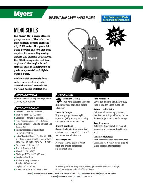
effluent and drain water pumpS<strong>ME40</strong> seriesThe Myers® <strong>ME40</strong> series effluent<strong>pumps</strong> are one of the industry'smost efficient models featuringa 4/10 HP motor. This powerfulpump provides the flow and headrequired for demanding dosingsystems and drainage applications.The <strong>ME40</strong> incorporates cast iron,engineered thermoplastic andstainless steel in <strong>com</strong>bination toproduce a powerful and highlydurable pump.Available with automatic floatswitch or manual models foruse with external controls forprecision dosing installations.APPLICATIONS<strong>Effluent</strong> removal, sump drainage, watertransfer, flood controlSPECIFICATIONSn Capacities – 80 GPM (303 LPM)n Shut-off Head – 32' (9.75 m)n Operation – Manual or automaticn Max. Spherical Solids – 3/4" (19 mm)n Liquids Handling – Domestic effluent anddrain watern Intermittent Liquid Temperature –Up to 140°F (60°C)n Motor/Electrical Data – 4/10 HP, 1650 RPM,oil-filled, permanent split capacitor type,115V, 12A, 1Ø, 60Hz; 230V, 6A, 1Ø, 60Hzn Acceptable pH Range – 5-9n Specific Gravity – .9-1.1n Viscosity – 28-35 SSUn Discharge, NPT – 1-1/2" (38 mm)n Housing – Cast ironn Minimum Sump Diameter –Simplex: 24" (61.0 cm)Duplex: 36" (91.4 cm)n Power Cord – 10' or 20', 16/3, SJTWFEATURESEfficient DosingTwo-vane cast iron impellerdesign provides maximum dosingefficiencyNEW!Powerful TorqueHigh-torque, permanent splitcapacitor (PSC) motor; no startingswitches or relays to wear outRugged and CoolRugged-built, oil-filled motor forcontinuous bearing lubrication andmaximum heat dissipationWater-tight FitPositive sealing, quick-connectfloat and switch cords makereplacement easyNEW!Cast IronImpellerSeal ProtectionLower ball bearing and heavy dutyType 6 seal for added pump lifeAutomatically BetterField-tested, wide-angle, mercuryfreefloat switch provides maximumdrawdown (automatic models only)Dual OperationAutomatic float switch or manualoperation by plugging directly intooutletThermal ProtectionHeat sensor overload protection withautomatic reset when motor cools toa safe operating temperatureIn order to provide the best products possible, specifications are subject to change.Myers® is a registered trademark of Pentair Water.Myers | Customer Service: 888.987.8677 | Fax Orders: 888.840.7867 | www.myerspump.<strong>com</strong> | Form No. M9022SSECanada | Phone: 519.748.5470 | Fax: 519.748.25531
effluent and drain water pumpSORDERING INFORMATIONCatalog Phase/ Discharge Switch Cord Approx. Wt.Number HP Volts Cycles Amps Size Type Length Lbs.<strong>ME40</strong>A-11 4/10 115 1/60 12.0 1-1/2" Tethered Automatic 10' 27<strong>ME40</strong>AC-11 4/10 115 1/60 12.0 1-1/2" Tethered Automatic 20' 28<strong>ME40</strong>M-11 4/10 115 1/60 12.0 1-1/2" Manual 10' 26<strong>ME40</strong>MC-11 4/10 115 1/60 12.0 1-1/2" Manual 20' 27<strong>ME40</strong>AC-21 4/10 230 1/60 6.0 1-1/2" Tethered Automatic 20' 28<strong>ME40</strong>MC-21 4/10 230 1/60 6.0 1-1/2" Manual 20' 27<strong>ME40</strong>P-1 4/10 115 1/60 6.0 1-1/2" Tethered Automatic* 10' 28<strong>ME40</strong>PC-1 4/10 115 1/60 6.0 1-1/2" Tethered Automatic* 20' 29<strong>ME40</strong>PC-2 4/10 230 1/60 6.0 1-1/2" Tethered Automatic* 20' 29*PiggybackDIMENSIONS PUMP PERFORMANCECapacity liters per minute0 50 100 150 200 250 3004012351030Total head in feet252015<strong>ME40</strong> 4/10HP864Total head in meters105200 10 20 30 40 50 60 70 80Capacity gallons per minute0Myers | Customer Service: 888.987.8677 | Fax Orders: 888.840.7867 | www.myerspump.<strong>com</strong> | Form No. M9022SSECanada | Phone: 519.748.5470 | Fax: 519.748.25532
effluent and drain water pumpSSPECIFICATIONSEFFLUENT PUMPS – Pump(s) shall be F. E. Myers <strong>ME40</strong> <strong>Series</strong> sump <strong>pumps</strong> selected in accordance with the followingdesign criteria:Number of Pumps: _____________________Primary Design Flow: _____________________Primary Design Head: _____________________Minimum Shut-off Head: 32'Motor Horsepower: 4/10Motor Speed:1650 RPMElectrical:115 Volts, 1Ø, 60 Hz or230 Volts, 1Ø, 60 HzPUMP – The pump shall be designed to handle septic tank effluent and be capable of passing 3/4 inch spherical solids.The pump shall be capable of handling liquids with temperatures to 140°F intermittent.MOTOR – The pump motor shall be of the submersible type rated 4/10 hp at 1650 RPM and shall be for _____115 voltsor _____230 volts single phase, 60 cycles. Single phase motor shall be of the shaded pole type with no relays orstarting switches. Stator winding shall be of the open type with Class A insulation rated for 105°C maximum operatingtemperature. The winding housing shall be filled with clean dielectric oil to lubricate bearings and seals, and transferheat from the windings to the outer shell. The motor winding assembly shall be pressed into the stator housing forbest alignment and heat transfer.The motor shall be capable of operating over the full range of the performance curve without overloading the motorand causing any objectionable noise or vibration. The motor shall have two bearings to support the rotor; an uppersleeve bearing to ac<strong>com</strong>modate radial loads and a lower sleeve bearing with thrust pad to take thrust and radial loads.A heat sensor thermostat and overload shall be attached to the top end of the motor windings and shall be wired inseries with the windings to stop the motor if the motor winding temperature reaches 221°F. The overload thermostatshall reset automatically when the motor cools to a safe operating temperature.POWER CORD – The motor power cord shall be _____10 or _____20 feet SJOW or SJTW type. The power and switchcords shall be of the positive sealing, quick-disconnect type. The power and switch cable connections shall be sealed atthe motor entrance by means of a <strong>com</strong>pression nut which serves to make a positive electrical connection and preventwater from entering the cable jacket and motor housing.OPTIONAL CONTROL SWITCH – The effluent pump shall be controlled by an optional integral float switch. The floatswitch shall be of a non-mercury type and be capable of directly controlling the pump motor without the need for anexternal control panel.SHAFT SEAL – The motor shall be protected by a rotating mechanical shaft seal. The seals shall have carbon and ceramicseal faces lapped to a tolerance of one light band. Metal parts and springs for seals shall be stainless steel.PUMP IMPELLER – The pump impeller shall be of the two vane enclosed type. The impeller shall be constructed ofcast iron.MOTOR CASTINGS – The motor housing castings shall be of high tensile strength Class 30 gray cast iron. Castings shallbe treated with phosphate and painted with a high quality air dried modified epoxy resin for corrosion protection.PUMP CASE – The pump case shall be a high efficiency volute design capable of passing 3/4 inch spherical solids. Thepump volute shall be constructed of corrosion resistant, high impact, engineered thermoplastic.FASTENERS – All exposed fasteners shall be of stainless steel.Myers | Customer Service: 888.987.8677 | Fax Orders: 888.840.7867 | www.myerspump.<strong>com</strong> | Form No. M9022SSECanada | Phone: 519.748.5470 | Fax: 519.748.25533
effluent and drain water pumpSMyers | Customer Service: 888.987.8677 | Fax Orders: 888.840.7867 | www.myerspump.<strong>com</strong> | Form No. M9022SSE (11/08)Canada | Phone: 519.748.5470 | Fax: 519.748.2553
<strong>ME40</strong>/<strong>ME40</strong>AG SERIESSubmersible Sump,<strong>Effluent</strong> & Sewage PumpsInstallation and Service ManualAutomatic and manual models. Single phase power only — 115 or 230 volt.23833A245 (Rev. 8/6/09)
DESCRIPTION AND APPLICATION<strong>ME40</strong>Myers <strong>ME40</strong> <strong>Series</strong> Pumps are single seal units,automatic or manual, designed for use in effluentdosing. Septic Tank <strong>Effluent</strong> Pumping (S.T.E.P.) ornormal sump and general dewatering applicationswhere higher pressure is required. DO NOT USE FORRAW SEWAGE.When used in effluent dosing or S.T.E.P. applications,the pump must be installed in a separate tank or<strong>com</strong>partment at the discharge side of the septic tank.NEVER INSTALL PUMP IN MAIN TANK WHERESLUDGE COLLECTS.Impellers are enclosed two-vane type to handle3/4” spherical solids and are made of engineeredthermoplastic. All <strong>pumps</strong> have a 1-1/2” NPTdischarge tapping. NOTE: DO NOT OVERTIGHTENDISCHARGE PIPE INTO PUMP PLASTICDISCHARGE FITTING.GeneralThese <strong>pumps</strong> are available in 115 volt or 230 volt,single phase, 4/10 HP motors. All units are single sealonly, available in automatic or manual with either 10’ or20’ power cords. All power cords have either 115 voltor 230 volt grounded plugs.These <strong>pumps</strong> are NOT for use in swimming pools orfountains.<strong>ME40</strong>AGThe <strong>ME40</strong>AG <strong>Series</strong> Pumps are single seal unitsdesigned for use in continuous run agriculturalevaporative cooling applications. They will runcontinuously in elevated temperatures with cleansump water.The wetted pump <strong>com</strong>ponents are the same asalready described for the <strong>ME40</strong> series.AIR LOCKINGA sump pump is said to be air locked if water traps airin the pump and it cannot get out, thus preventing thepump from operating.The <strong>ME40</strong>/<strong>ME40</strong>AG <strong>pumps</strong> have a 1/16” air vent holein the impeller chamber to let out trapped air. If thishole be<strong>com</strong>es plugged, the pump may air lock. Asa secondary precaution a 1/8” hole should be drilledin the discharge pipe below the check valve. Thecheck valve should be 12 to 18 inches above pumpdischarge. Do not put check valve directly into pumpdischarge opening.PACKAGINGEach pump is packaged separately in a carton markedwith a catalog number and Myers engineering number.Catalog Engineering CordNo. No. HP V Ph Lgth. Type<strong>ME40</strong>A-11 25300D000 4/10 115 1 10’ Auto<strong>ME40</strong>M-11 25300D001 4/10 115 1 10’ Manual<strong>ME40</strong>AC-11 25300D010 4/10 115 1 20’ Auto<strong>ME40</strong>MC-11 25300D011 4/10 115 1 20’ Manual<strong>ME40</strong>AC-21 25300D012 4/10 230 1 20’ Auto<strong>ME40</strong>MC-21 25300D013 4/10 230 1 20’ Manual<strong>ME40</strong>P-1 25300D900 4/10 115 1 10’ Auto<strong>ME40</strong>PC-1 25300D901 4/10 115 1 20’ Auto<strong>ME40</strong>P-2 25300D902 4/10 230 1 10’ Auto<strong>ME40</strong>PC-2 25300D903 4/10 230 1 20’ Auto<strong>ME40</strong>AG-11 27234D001 4/10 115 1 20’ Manual<strong>ME40</strong>AG-21 27234D002 4/10 230 1 20’ ManualLEVEL CONTROLSAll <strong>pumps</strong> must use sealed level control switches forautomatic operation. All automatic <strong>pumps</strong> have builtinlevel control float switches. The power cord has aGROUND PIN that plugs into a grounded receptacle.The grounded receptacle cannot be used in the wetsump or basin due to DANGER of current leakage.Manual <strong>pumps</strong> can be made automatic with MLC orMFLC controls with a series plug. Plug the MLC orMFLC witch cord series plug into a proper voltageGROUNDED RECEPTACLE. Then plug the pumpcord plug into the back of the switch cord series plug.NOTE: The float control must be tethered a minimum4” to pump or discharge pipe. Control must float freefrom pump and basin wall.On all duplex units or simplex installations withadditional options like high water alarm, the powercord plug must be cut off and wired into a controlpanel or into a sealed junction box if used in wet sumpor basin. The AWS-1 control also acts as a sealedjunction box for connecting power cord to pump cord.NOTE: The <strong>ME40</strong> sump/effluent pump can be easilychanged from one style, automatic or manual, to theother by only interchanging the plug ends of the floatcontrol with the manual plug. The ball float must betethered with a cable clamp, asshown. DO NOT REMOVE THEMOTOR CAP.The <strong>ME40</strong>P <strong>pumps</strong> have amechanical (mercury free) floatswitch with a 10’ or 20’ cord with a115 volt or 230 volt piggybackplug with the switch mounted tothe pump. Plug the switch cordplug into a proper voltage, properlygrounded outlet and plug thepower cord into the back of theswitch cord and tape the cords tothe discharge pipe every 12”.23833A245 2
DESIGN OF PRESSURE SEWER SYSTEMSMyers has available <strong>com</strong>plete <strong>com</strong>puter software fordesigning PRESSURE SEWER SYSTEMS. Thisgives pipe sizes to use and gives exact flow fromany pump or group of <strong>pumps</strong> in the system whenoperating simultaneously. This design DISK for IBM®or COMPATIBLE <strong>com</strong>puters is available to engineerson request.MOTOR TYPEThe motors used in the <strong>ME40</strong>/<strong>ME40</strong>AG <strong>pumps</strong> arepressed into the cast iron housing and surrounded bydielectric oil for the greatest heat dissipation. The<strong>ME40</strong> uses a shaded pole, 4/10 HP, 1550 RPM motor.The <strong>ME40</strong>AG uses a permanent split capacitor, 4/10HP, 1625 RPM motor. Both units have Class A motorinsulation, are available in single phase 115 or 230 voltwith overload protection, and use a lower ball bearing -upper sleeve bearing. These <strong>pumps</strong> have no startingswitches and do not require a control panel for simplexinstallation.SAFETY WARNINGSWARNING: Risk of electric shock. Pumps aresupplied with a grounding conductor and groundingtypeattachment plug on the power cord. To reducethe risk of electric shock, be certain that it isconnected only to a properly grounded, groundingtypereceptacle. DO NOT cut off ground pin or use anadapter fitting. DO NOT use an extension cord withthis pump. Entire plug may be cut off it a control panelis used.When wiring this pump, follow all local electrical andsafety codes and ordinances as well as the mostrecent National Electric Code (NEC-ANSI/NFPA 70).All <strong>pumps</strong> have a GROUND WIRE that is connected tothe motor. This wire goes to the receptacle or controlpanel which must be connected to a good outsideGROUND such as a metal water pipe or GROUNDSTAKE DRIVEN AT LEAST 8 feet into the ground.UL AND CSA APPROVALAll <strong>pumps</strong> have UL and CSA approval. Myers is aSSPMA certified pump member.INSTALLATIONWARNING: Basin or tank must be vented inaccordance with local plumbing codes. These <strong>pumps</strong>are not designed for and CANNOT be installed inlocations classified as hazardous in accordance withthe National Electric Code ANSI/NFPA 70.CAUTION: Never enter pump chamber aftersewage or effluent has been in basin. Sewagewater can give off methane, hydrogen sulfide, andother gasses which are highly poisonous. For thisreason, Myers re<strong>com</strong>mends installing effluent <strong>pumps</strong>with a quick removal system. The quick removalsystem may be a union or Cam-lok® coupling ifthe pipe or discharge hose is within reach from thesurface, or a rail system type quick disconnect ondeeper installations. See installation drawings forsuggested installation.The dosing tank or pumping chamber must beconstructed of corrosion resistant materials and mustbe capable of withstanding all anticipated internal andexternal loads. It also must not allow infiltration orexfiltration. The tank must have provisions for antibuoyancy.Access holes or covers must be adequatesize and be accessible from the surface to allow forinstallation and maintenance of the system. Accesscovers must be lockable or heavy enough to preventeasy access by unauthorized personnel. The pumpingchamber holding capacity should be selected to allowfor emergency conditions.The discharge pipe must be the same size as the pumpdischarge, 1-1/2” or larger. In order to insure sufficientfluid velocity to prevent any residual solids fromcollecting in the discharge pipe, it is re<strong>com</strong>mended thata minimum flow of 2’ per second be maintained. (12GPM through 1-1/2” pipe, 21 GPM through 2” pipe and46 GPM through 3” pipe). It is re<strong>com</strong>mended that PVCor equal pipe is used for corrosion resistance. A full flow(ball or gate) shut-off valve must be installed to preventback flow of effluent if the pump must be removed forservice. A check valve must be installed on pressuresewer systems and on other systems where conditionsallow to prevent back flow and to reduce wear on thepump system.A high water alarm must be installed on a separatecircuit from the pump circuit. The alarm should havethe ability to be tested for proper operation.SCREEN<strong>ME40</strong>AG <strong>pumps</strong> have a suction screen included inthe packaging. To secure the screen in place use twoscrews (provided). Screen installation, maintenance,and cleaning is the responsibility of the pump owner.BEFORE DISMANTLING PUMP FORREPLACEMENT OF PARTSClean pump thoroughly. Knock off all scale anddeposits. Submerge <strong>com</strong>plete unit in Clorox solutionfor one hour before taking apart.323833A245
<strong>ME40</strong> TYPICAL INSTALLATION23833A245 4
DIMENSIONS[Dimensions in mm]1½” NPTDischarge9.19”[233]12.44”[316]3.75”<strong>ME40</strong>Level Control11.68”[297]5.66”[144]3.89”[99]<strong>ME40</strong>AGSuction Screen<strong>ME40</strong> PERFORMANCE CURVE<strong>ME40</strong>AG PERFORMANCE CURVE408.0035115 VOLT AMPS7.00306.00TOTAL HEAD IN FEET252015230 VOLT AMPS60HZ PERFORMANCE5.004.003.00POWER (AMPS)102.0050HZ PERFORMANCE51.0000 10 20 30 40 50 60 70 8010 20 30 40 50 60 70 80CAPACITY (GPM)TOTAL GALLONS PER MINUTE0.00523833A245
TROUBLE CHECK LISTCONDITIONPump does not run or start whenwater is up in tank.Pump runs but does not deliver flowPROBABLE CAUSE1. Check for blown fuse or tripped circuit breaker.2. Check for defective level switch.3. Where control panel is used be sure H-O-A switch is in theAUTO position. If it does not run, turn switch to the HANDposition and if the pump runs then the trouble is in the automaticelectrical system. have ELECTRICIAN make electricalchecks.4. Check for burned out motor. Occasionally lightning can damagea motor even with lightning protection.5. Where plug-in cords are used be sure contact blades areclean and making good contact. DO NOT USE PLUG-INCORDS INSIDE A SUMP OR WET WELL.6. Level control ball or weight may be stuck on side of basin. Besure it floats freely.1. Check for air lock. Start and stop pump several times, if thisdoes not help it may be necessary to loosen a union in thedischarge line to relieve air lock.2. Check valve may be installed backwards. Check flow arrowon valve body. Check shut-off valve. It may be closed.3. Check vertical elevation. It may be higher than pump candevelop. (see pump curve)4. Pump inlet may be plugged. Remove pump to check.CAUTION: ALWAYS UNPLUG POWER CORDS OR TURN OFF ALL MAIN AND BRANCH CIRCUIT BREAK-ERS BEFORE DOING ANY WORK ON THE PUMP. If control panel is remote from pump, disconnect leadwires to motor so that no one can turn the circuit breaker back on.23833A245 6
5. Lay pump on its side. Place a flat screwdriverin the slot in the bottom of the shaft and turn theimpeller counterclockwise to remove it from theshaft. A blow from a rubber hammer may benecessary to loosen the impeller. Discard old sealpart.6. Remove the four flat head screws holding theupper half of volute to housing. Note position ofdischarge in relation to switch clamp.7. To assemble the new ceramic seal seat into yournew stator housing assembly, clean the seat cavitythoroughly and follow Steps 7 & 8 “For Shaft SealOnly Replacement”. NEVER USE OLD SEALPARTS. USE ONLY COMPLETELY NEW SEALS.8. Assemble the upper half of the volute to housingwith the four flat head screws. Position dischargethe same as before in relation to switch clamp.9. Make sure the shaft surface is clean and lightlyoiled. Press by hand the rotating half of the shaftseal onto the shaft. Be sure the rotating carbonwasher is positioned adjacent to the ceramic seat.10. Screw the impeller clockwise onto the shaft usinga screwdriver to hold the shaft from turning andtighten impeller. Use Loctite or equal on shaftthreads.12. Check that the impeller turns freely.13. Guide the four motor wires up through a <strong>com</strong>monhole in the bearing plate and place the protectiveplastic tube over the four motor wires.14. Position the o-ring into cap and reconnect the fourmotor wires as shown in wiring diagram. The twogreen ground wires connect to the pins nearest the‘G’ marked on the cap.15. Put oil in the motor housing using only Myerssubmersible transformer oil. The oil should beabout 1/2” above the surface of the bearing plate.16. Reinstall the top thermoplastic cap, making surethe o-ring is in position on the cap. Tighten the topsix screws snug, but do not overtighten.17. Be sure the 1/8” NPT pipe plug is in the top cap.18. Plug pump into receptacle to test operation. Pumpmust run quiet and free of vibration.NOTE: When replacing top cap with a new one, besure the jumper wire and pipe plug are in place. Seewiring diagram. Tether level control to motor housingwith float extended 3-5/8” to 4”.11. Place pump upright on top of lower volute half. Besure mating parts are together and reassemble theeleven machine screws and tighten.WIRING DIAGRAMMOTOR REISTANCE CHARTWindingLockedResistance Max. RotorModel HP Speed V Ph in Ohms Amps Amps<strong>ME40</strong> 4/10 1550 115 1 1.2 12.0 16.0<strong>ME40</strong> 4/10 1550 230 1 4.3 6.0 8.2<strong>ME40</strong>AG 4/10 1650 115 1 2.0 8.0 17.6<strong>ME40</strong>AG 4/10 1650 230 1 9.1 4.0 8.823833A245 8
TYPICAL SECTION DRAWING FOR <strong>ME40</strong> SERIESShaded Pole Motor923833A245
TYPICAL SECTION DRAWING FOR <strong>ME40</strong>AG SERIESPSC Motor23833A245 10
PARTS LIST <strong>ME40</strong>/<strong>ME40</strong>AGRef. No. PartNo. Description Req’d Numbers1A Plug, nut (manual only) 1 24448A0001B Washer (manual only) 1 05030A2131C Plug, connector (manual only) 1 24449A0002 Cord, electric 1 See Chart3 Cap, motor (not stamped) 1 24431C0004 Wire with terminals 1 09859A8005 Capacitor (115 volt) 1 26446A0005 Capacitor (230 volt) 1 23290A0006 Cradle, capacitor (230 volt) 1 26298B0007 O-Ring, 5-1/2 x 5-1/4 x 1/8 1 05876A1468 Washer, spring wave 1 19331A0119 Plate, bearing 1 24661B00010 Oil, transformer (1 gal.) .2 gal. 11009A00811 Housing, with rotor & stator 1 See ChartStator only 1 See ChartRotor & shaft, <strong>ME40</strong> 1 25309A000Rotor & shaft, <strong>ME40</strong>AG 1 26166B000Housing only 1 27313C000Ref. No. PartNo. Description Req’d Numbers12 Seal, shaft 1 21607A01513 Screw, machine, flat head 4 07597A03014 Case, volute, upper half 1 25306D00015 Screws, self tap #10 x 3/4 11 05910A01216 Impeller 1 25301B90016A Sealant, Loctite 242 1 14550A00117 Case, volute, lower half 1 25307D00118 Gasket, Vellumoid 1 25328C00019 Ball bearing 1 00065024120 Screws, hex head mach. 6 18475A00321 Suction screen 1 25307A01522 Level control 1 See ChartCHART2 11 22Pump Pump HousingCatalog Engineering Pump Cord, Cord w/Rotor Stator LevelNumber Numbers Type Electric Length & Stator Only Control<strong>ME40</strong>A-11 25300D000 Automatic 21628B017 10’ 27313C010 21599B022 25798A550<strong>ME40</strong>M-11 25300D001 Manual 21628B027 10’ 27313C010 21599B022 ---<strong>ME40</strong>AC-11 25300D010 Automatic 21628B018 20’ 27313C010 21599B022 25798A550<strong>ME40</strong>MC-11 25300D011 Manual 21628B018 20’ 27313C010 21599B022 ---<strong>ME40</strong>AC-21 25300D012 Automatic 21628B019 20’ 27313C011 21599B023 25798A550<strong>ME40</strong>MC-21 25300D013 Manual 21628B019 20’ 27313C011 21599B023 ---<strong>ME40</strong>P-1 25300D900 Automatic 21628B041 10’ 27313C010 21599B022 21813B130<strong>ME40</strong>PC-1 25300D901 Automatic 21628B018 20’ 27313C010 21599B022 21813B131<strong>ME40</strong>PC-2 25300D903 Automatic 21628B019 20’ 27313C011 21599B023 21813B133<strong>ME40</strong>AG-11 27234D001 Manual 21628B044 20’ 27313C012 26165B000 ---<strong>ME40</strong>AG-21 27234D002 Manual 21628B043 20’ 27313C013 26165B001 ---1123833A245
LIMITED WARRANTYF.E. MYERS warrants to the original consumer purchaser (“Purchaser” or “You”) of the products listed below,that they will be free from defects in material and workmanship for the Warranty Period shown below.ProductSump/Sewage/<strong>Effluent</strong> ProductsFibrewound TanksSteel Pressure TanksJet <strong>pumps</strong>, small centrifugal <strong>pumps</strong>,submersible <strong>pumps</strong> and related accessoriesWarranty Period24 months from date of manufacture5 years from date of original installation5 years from date of original installationwhichever occurs first:12 months from date of original installation, or18 months from date of manufactureOur warranty will not apply to any product that, in our sole judgement, has been subject to negligence,misapplication, improper installation, or improper maintenance. Without limiting the foregoing, operating athree phase motor with single phase power through a phase converter will void the warranty. Note also thatthree phase motors must be protected by three-leg, ambient <strong>com</strong>pensated, extra-quick trip overload relays ofthe re<strong>com</strong>mended size or the warranty is void.Your only remedy, and F.E. MYERS’s only duty, is that F.E. MYERS repair or replace defective products (atF.E. MYERS’s choice). You must pay all labor and shipping charges associated with this warranty and mustrequest warranty service through the installing dealer as soon as a problem is discovered. No request forservice will be accepted if received after the Warranty Period has expired. This warranty is not transferable.F.E. MYERS SHALL NOT BE LIABLE FOR ANY CONSEQUENTIAL, INCIDENTAL, OR CONTINGENTDAMAGES WHATSOEVER.THE FOREGOING WARRANTIES ARE EXCLUSIVE AND IN LIEU OF ALL OTHER EXPRESS ANDIMPLIED WARRANTIES, INCLUDING BUT NOT LIMITED TO THE IMPLIED WARRANTIES OFMERCHANTABILITY AND FITNESS FOR A PARTICULAR PURPOSE. THE FOREGOING WARRANTIESSHALL NOT EXTEND BEYOND THE DURATION EXPRESSLY PROVIDED HEREIN.Some states do not allow the exclusion or limitation of incidental or consequential damages or limitations onthe duration of an implied warranty, so the above limitations or exclusions may not apply to You. This warrantygives You specific legal rights and You may also have other rights which vary from state to state.This warranty supersedes and replaces all previous warranty publications.F.E. MYERS1101 Myers Parkway, Ashland, OH 44805-1989Phone: 888-987-8677 • Fax: 888-840-7867 • www.femyers.<strong>com</strong>F. E. Myers, 1101 Myers Parkway, Ashland, OH 44805-1969888-987-8677, FAX: 888-840-7867, www.femyers.<strong>com</strong>Myers (Canada), 269 Trillium Drive, Kitchener, Ontario N2G 4W5519/748-5470, FAX: 519/748-255323833A245 12