Solenoid valves - Bürkert Fluid Control Systems
Solenoid valves - Bürkert Fluid Control Systems
Solenoid valves - Bürkert Fluid Control Systems

You also want an ePaper? Increase the reach of your titles
YUMPU automatically turns print PDFs into web optimized ePapers that Google loves.
System Catalog 1<br />
<strong>Solenoid</strong> <strong>valves</strong> I Process and control <strong>valves</strong> I Pneumatics<br />
Sensors I Micro<strong>Fluid</strong>ics I MFC and proportional <strong>valves</strong><br />
The smart choice of <strong>Fluid</strong> <strong>Control</strong> <strong>Systems</strong>
All technical details were valid at the<br />
time of going to print. Since we are<br />
continuously developing our products,<br />
we reserve the right to make technical<br />
alterations. Unfortunately, we also<br />
cannot fully exclude possible errors.<br />
Please understand that no legal claims<br />
can be made bared upon either the<br />
details given or the illustrations and<br />
descriptions provided.<br />
Texts, photographs, technical drawings<br />
and any other form of presentations<br />
made in this publication are protected<br />
by copyright and property of<br />
Bürkert <strong>Fluid</strong> <strong>Control</strong> <strong>Systems</strong> GmbH<br />
& Co. KG.<br />
Any further use in print or electronic<br />
media requires the express approval<br />
of Bürkert GmbH & Co. KG. Any form<br />
of duplication, translation, processing,<br />
recording on microfilm or saving in<br />
electronic systems is prohibited without<br />
the express approval of<br />
Bürkert GmbH & Co. KG.<br />
Bürkert GmbH & Co. KG<br />
<strong>Fluid</strong> <strong>Control</strong> <strong>Systems</strong><br />
Christian-Bürkert-Straße 13-17<br />
D-74653 Ingelfingen
Contents<br />
A quite “everyday” technology Page 6<br />
1. <strong>Solenoid</strong> systems for solenoid <strong>valves</strong> Page 8<br />
1.1. <strong>Solenoid</strong> systems for solenoid <strong>valves</strong> Page 8<br />
1.2. The basic operating principle of a solenoid Page 8<br />
1.3. <strong>Solenoid</strong> coils for direct current and alternating current Page 9<br />
1.3.1. <strong>Solenoid</strong> coils for direct current Page 9<br />
1.3.2. <strong>Solenoid</strong> coils for alternating current Page 10<br />
1.4. Stroke-force behavior of DC and AC solenoids Page 12<br />
1.5. Coil design and self-heating Page 13<br />
1.6. Special coils Page 14<br />
1.6.1. <strong>Solenoid</strong> coils with high-performance electronics Page 14<br />
1.6.2. Impulse coils Page 14<br />
1.6.3. Explosion-proof coils Page 15<br />
1.7. Type of protection and electrical connection Page 15<br />
1.7.1. Type of protection for electrical equipment Page 15<br />
2. Functional principles Page 16<br />
2.1. <strong>Fluid</strong>ic circuit symbols, designation of the circuit functions and their meaning Page 17<br />
2.2. Direct-acting solenoid <strong>valves</strong>: plungers Page 18<br />
2.2.1. 2/2-way plunger-type solenoid <strong>valves</strong> Page 18<br />
2.2.2. 3/2-way plunger-type solenoid <strong>valves</strong> Page 19<br />
2.2.3. Direct-acting solenoid <strong>valves</strong>: pivoted-armature <strong>valves</strong> Page 20<br />
2.2.4. Direct-acting solenoid <strong>valves</strong>: 3/2-way rocker valve Page 20<br />
2.2.5. Characteristics and possible applications of various solenoid actuators<br />
for solenoid <strong>valves</strong> Page 21<br />
2.3. Servo-assisted solenoid <strong>valves</strong> Page 22<br />
2.3.1. Servo-assisted 2/2-way solenoid <strong>valves</strong> with diaphragm Page 23<br />
2.3.2. Servo-assisted solenoid <strong>valves</strong> with piston Page 24<br />
2.3.3. Force pilot operated solenoid <strong>valves</strong> Page 25<br />
2.3.4. Servo-assisted solenoid <strong>valves</strong> with 3/2-way pilot Page 26<br />
3. Basics of dynamic fluid mechanics Page 27<br />
3.1. Flow behavior of solenoid <strong>valves</strong> for fluidics Page 27<br />
3.1.1. Differences with respect to application areas Page 27<br />
3.2. Flow behavior and kv value of fluids Page 27<br />
3.2.1. Volume flow and mass flow Page 27<br />
3.2.2. k v value Page 28<br />
3.2.3. c v value and QN n value Page 28<br />
3.2.4. Inter-relationship between volume flow and k v value Page 29<br />
3.3. Flow behavior with gases Page 29<br />
3.3.1. Mass flow and volume flow with gases Page 29
3.3.2. Outflow function and critical pressure ratio Page 30<br />
3.3.3. Sub-critical and super-critical outflow Page 30<br />
3.3.4. Everyday formulae for mass flow and volume flow with gases Page 31<br />
3.4. Opening and closing operations in pipes with fluids Page 32<br />
3.4.1. Origination and propagation of pressure waves Page 32<br />
3.4.2. Opening and closing times of solenoid <strong>valves</strong> Page 33<br />
3.4.3. Origination of suction surges with fluids Page 33<br />
3.4.4. Origination of pressure surges with fluids Page 34<br />
3.4.5. Example calculation Page 36<br />
3.4.6. <strong>Solenoid</strong> <strong>valves</strong> Page 37<br />
4. Materials for Bürkert solenoid <strong>valves</strong> Page 38<br />
5. Approvals Page 40<br />
5.1. European explosion protection, ATEX Directives (formerly Explosion Protection Direct.) Page 40<br />
5.2. International approvals Page 41<br />
5.3. National approvals Page 41<br />
5.3.1. VDE approval as water valve for domestic use Page 41<br />
5.3.2. KTW Recommendations (Plastics in Drinking Water)/W270 DV6W Page 41<br />
5.3.3. ZApproval as safety shut-off valve Page 41<br />
5.4. European approvals Page 42<br />
5.4.1. Existing approvals at Bürkert Page 42<br />
5.5. North American approvals Page 43<br />
5.6. International approvals Page 43<br />
6. From the application to the right product Page 44<br />
6.1. <strong>Solenoid</strong> <strong>valves</strong> for water and other neutral media Page 44<br />
6.2. <strong>Solenoid</strong> <strong>valves</strong> for neutral gaseous media Page 46<br />
6.3. <strong>Solenoid</strong> <strong>valves</strong> for aggressive media Page 48<br />
6.4. <strong>Solenoid</strong> <strong>valves</strong> for steam up to 180 °C Page 50<br />
6.5. <strong>Solenoid</strong> <strong>valves</strong> for high pressure Page 51<br />
7. Always unique Page 52<br />
7.1. Safety valve for burner control Page 53<br />
7.2. Cooling water distribution Page 54<br />
7.3. <strong>Control</strong> device for lubrication equipment Page 55<br />
7.4. Vacuum block for tightness control of serial parts Page 56<br />
7.5. Water block for compressors Page 57<br />
7.6. Valve block for the food industry, valve block in the test units Page 58<br />
7.6.1. Bellows <strong>valves</strong> Page 59<br />
7.7. <strong>Solenoid</strong> <strong>valves</strong> in fuel cell technology Page 60<br />
List of keywords Page 62
A quite “everyday” technology<br />
Technology from Bürkert, particularly<br />
solenoid valve technology, is not only<br />
encountered in industrial installations<br />
in an extremely wide variety of sectors,<br />
it can also be found literally on the<br />
street: inside many useful devices and<br />
apparatuses that make our daily life<br />
easier. For example, at each and every<br />
service station. Gas pump nozzles respond<br />
precisely down to the cent with<br />
Bürkert solenoid valve technology. Tire<br />
inflation pressure is checked and oil<br />
extractions carried out using our technology,<br />
as are car-wash operations<br />
with their various programs and, last<br />
but not least, Bürkert solenoid valve<br />
technology ensures filling of the main<br />
tanks and reliable operation of the<br />
sprinkler system. Even the cup of coffee<br />
we buy from a vending machine is<br />
not an exception: Bürkert technology<br />
takes care of the dosing. It is no wonder<br />
that our engineers are just a bit<br />
proud of the fact that their ideas are<br />
so welcome in everyday applications.<br />
Evolution of core<br />
competence<br />
Our company has never outsourced<br />
the further development of solenoid<br />
valve technology, not even sub-areas<br />
of this technology. After all, it is with<br />
6/7
a complex system solution, we always<br />
focus on optimum process reliability,<br />
efficiency and economy. Two essential<br />
parameters for future-proof solenoid<br />
valve technology are maximum repeat<br />
accuracy and minimum downtimes.<br />
This is where Bürkert brings its<br />
strengths to the fore, strengths based<br />
on decades of experience gained by a<br />
pioneer in the industry. We are motivated<br />
anew every day by our goal of passing<br />
on this experience to our customers<br />
and advancing their success. The<br />
result is systematic solutions offering<br />
an optimum combination of technical<br />
and economic benefit for every process.<br />
Efficient technology<br />
for your application<br />
solenoid valve technology in particular<br />
that Bürkert has achieved its position as<br />
market leader in fluidics. It is one of the<br />
main pillars of our company success,<br />
and one which first and foremost represents<br />
an advantage for our customers:<br />
the ongoing, practically-oriented<br />
expansion of our competence as a<br />
pioneer in the industry is as good as a<br />
guarantee for groundbreaking innovations.<br />
The market confirms this. Bürkert<br />
is one of the top addresses worldwide<br />
for future-orientated solenoid valve<br />
technology.<br />
Process-integrated,<br />
systematic solutions<br />
Bürkert systematically follows the principle<br />
of maximum customer benefit<br />
when developing efficient solenoid<br />
valve technology. Regardless of whether<br />
you require a single component or<br />
When it comes to shutting off, releasing,<br />
dosing, distributing or mixing gases<br />
and fluids, solenoid <strong>valves</strong> are the most<br />
frequently used control elements. The<br />
sum of the applications mentioned above<br />
corresponds to a wealth of specialized<br />
and diversified solutions which<br />
have one thing in common. We make<br />
choosing the right component or the<br />
appropriate system as simple as possible.<br />
Since we consistently observe<br />
the market, we are most likely already<br />
familiar with your requirements. And<br />
should your needs be new to us, our<br />
engineers will meet the challenge with<br />
great motivation.
1. <strong>Solenoid</strong> systems for solenoid <strong>valves</strong><br />
1.1.<br />
Basics<br />
<strong>Solenoid</strong> <strong>valves</strong> are the most frequently<br />
used control elements in fluidics.<br />
Their tasks are to shut off, release,<br />
dose, distribute or mix gases and fluids.<br />
They are confronted with many different<br />
requirements in your application<br />
areas, e.g.<br />
■ fast and safe switching<br />
■ high reliability<br />
■ long service life<br />
■ good medium compatibility of the<br />
materials used<br />
■ low control power<br />
■ compact design.<br />
Besides the plunger-type actuator<br />
which is used most frequently, pivotedarmature<br />
actuators and rocker actuators<br />
are also used.<br />
1.2.<br />
The basic operating<br />
principle of a solenoid<br />
While the actuation system, mechanical<br />
construction and the function as a<br />
whole do indeed differ, fundamental<br />
elements of the actuator are identical<br />
on virtually all actuation principles. The<br />
core of a solenoid consists of an electrical<br />
magnet, which is also referred to<br />
as a solenoid coil.<br />
I<br />
Coil<br />
If an electric current flows through an<br />
electrical conductor, e.g. an enameled<br />
copper wire, this wire also generates<br />
a magnetic field. This magnetic field<br />
can be amplified by focusing the electrical<br />
conductors in the form of a coil.<br />
In addition to the number of windings<br />
and the amperage, the iron circuit<br />
around the solenoid coil also has a<br />
substantial impact on the resultant<br />
magnetic forces. Normally, the polarity<br />
does not need to be noted.<br />
In the following, we will explain the<br />
mechanical construction of a solenoid<br />
actuator using the example of a plunger-type<br />
actuator.<br />
Magnetic flux<br />
Magnetic flux with electrical<br />
actuation of a coil<br />
8/9
Functional principle of a solenoid<br />
with plunger-type armature<br />
Connections<br />
Air gap/<br />
Valve stroke<br />
Stopper/<br />
Opposite armatur pole<br />
Winding<br />
Yoke<br />
1.3.1. <strong>Solenoid</strong> coils for direct<br />
current<br />
The coil design is relatively simple for<br />
DC coils. Depending on the required<br />
operating voltage, the electrical power<br />
results from the electrical resistance of<br />
the windings and the relevant voltage<br />
applied. On coils without integrated<br />
electronic components, the electrical<br />
resistance can be measured and the<br />
power can be calculated as follows:<br />
Non-magnetic core<br />
guide tube<br />
Moving core/<br />
Armature<br />
The magnetic field generated by the<br />
solenoid coil causes a force of attraction<br />
on the magnetic core located at<br />
the center, which is also frequently referred<br />
to as the plunger. The magnetic<br />
core is held by the coil for as long as<br />
current flows through the coil. If the<br />
flow of electric current is interrupted,<br />
a compression spring repels the core<br />
again and moves it back to its initial<br />
position.<br />
Stringent requirements are demanded<br />
on the core material used:<br />
■ good magnetization properties<br />
■ low magnetic memory effect<br />
■ high wear resistance<br />
■ high chemical resistance to aggressive<br />
media<br />
■ good mechanical workability.<br />
A seal which is connected permanently<br />
to the core thus causes a solenoid<br />
valve to open and close.<br />
1.3.<br />
<strong>Solenoid</strong> coils for<br />
direct current and<br />
alternating current<br />
Specific translatory armature movements<br />
can be executed with these two<br />
coil types, depending on the design.<br />
In addition, there are also specifically<br />
preferred applications and operating<br />
limits due to the physical laws for these<br />
two types. For example, DC coils are<br />
given preference in field bus technology.<br />
P = U2<br />
R<br />
P = Active power<br />
U = Operating voltage<br />
R = Coil resistance<br />
Neither eddy-current losses nor hysteresis<br />
losses occur on DC solenoids,<br />
so that the iron circuit can be designed<br />
as solid, whereby preference is given<br />
to iron grades with a low coercive field<br />
strength or low remanence in order to<br />
achieve low pull-off strengths. If defined<br />
return conditions are required, it is frequently<br />
essential to incorporate an air<br />
gap which causes shearing of the iron<br />
circuit and thus a reduction of remanence.<br />
One essential advantage of the<br />
DC solenoid is the delayed, gentle<br />
pick-up of the armature due to the degressive<br />
current rise and the silent<br />
holding function of the solenoid armature.
Copper<br />
shading<br />
ring<br />
Air gap<br />
Stopper<br />
1.3.2. <strong>Solenoid</strong> coils for alternating<br />
current<br />
On AC coils, the current is determined<br />
not only by the ohmic resistance of the<br />
windings, but also by the inductive<br />
resistance (reactance). The inductive<br />
resistance is significantly influenced<br />
by the position of the solenoid core. If<br />
the solenoid core has dropped out,<br />
the inductive resistance is lower and<br />
the coil current is higher. The current<br />
is thus higher in the pick-up phase than<br />
the coil current in the holding phase.<br />
As compared to a DC coil, coil resistance<br />
is far lower with the same voltage<br />
value being applied. Consequently, a<br />
coil should never be operated without<br />
a solenoid core when operating with<br />
AC voltage. Otherwise, there is a risk<br />
of the coil overheating and burning<br />
out after a few minutes.<br />
s<br />
Stationary guide<br />
Functional principle of an AC solenoid<br />
The inductive resistance is also dependent<br />
on the mains frequency. This is,<br />
for example, higher at 60 Hz than at<br />
50 Hz. If a solenoid coil designed for<br />
50 Hz is operated with 60 Hz, the magnetic<br />
force of attraction on the core will<br />
be lower. The loss of force is 10-30%<br />
depending on design and size. With<br />
direct-acting solenoid <strong>valves</strong>, this<br />
means restrictions in the pressure<br />
range for practical applications.<br />
If a coil designed for 60 Hz is operated<br />
with 50 Hz, this results in an increased<br />
power consumption with a higher coil<br />
temperature. The coil could be damaged<br />
under such extreme operating conditions.<br />
Winding<br />
Moving core/<br />
Armature<br />
One other special factor is the need<br />
for an electrically conductive ring<br />
(shading ring) in the stopper of the<br />
solenoid coil. If an AC solenoid was to<br />
be operated without the shading ring,<br />
the armature itself would constantly<br />
oscillate at the oscillation frequency of<br />
2 x mains frequency (50 Hz or 60 Hz),<br />
even with very slight forces of the return<br />
spring when energized since, with<br />
each zero crossover of the sinusoidal<br />
mains voltage, the holding force which<br />
represents a sinusoidal-quadratic curve<br />
drops practically to zero twice per period.<br />
Since this means that the force<br />
of the return spring increases above<br />
10/11
the holding force twice per period, the<br />
core would be lifted and attracted<br />
again twice per period. Such a very<br />
loud oscillation takes the form of a<br />
very unpleasant hum.<br />
If a correctly dimensioned shading ring<br />
is now fitted in the working gap, conventionally<br />
in the stationary opposite<br />
armature pole, a voltage is induced by<br />
the primary flux φp in the shading ring<br />
in the energized state of the armature,<br />
and this voltage generates a current<br />
which is phase-offset by angle ϕ in the<br />
shading ring. This phase-offset current<br />
now generates a secondary flux φs in<br />
the shading ring, which is phase-offset<br />
with respect to the primary flux φp by<br />
angle ϕ. This additional, phase-offset<br />
secondary flux φs now produces a<br />
quite different resultant force with<br />
which the minimum force and, thus, the<br />
holding force no longer drops to zero.<br />
The minimum holding force achieved<br />
in this way can be used for spring design<br />
and, along with the lifting force<br />
characteristic, represents the most<br />
important parameter when designing<br />
direct-acting solenoid <strong>valves</strong>.<br />
Stringent requirements in regards to<br />
evenness, flatness and peak-to-valley<br />
height are made on the pole faces of<br />
opposite armature (stopper) and core<br />
in order to achieve a hum-free holding<br />
force which is as high as possible.<br />
Larger air gaps between the poles very<br />
substantially reduce the holding force<br />
of the core since the magnetic conductivity<br />
of air is substantially poorer<br />
than that of iron.<br />
In practice, even a dirt deposit could<br />
cause hum and have major consequences<br />
for the coil and solenoid core. It<br />
may be necessary to use a DC coil<br />
with a series-connected rectifier when<br />
operating with AC voltage.
1.4.<br />
Stroke-force behavior<br />
of DC and AC<br />
solenoids<br />
The pick-up forces acting on the core<br />
are very greatly influenced by the core<br />
stroke (air gap). The greater the stroke,<br />
the lower the pick-up forces will be.<br />
This interrelationship is referred to as<br />
stroke-force.<br />
In addition to the spring force for returning<br />
the core, fluidic forces, triggered<br />
by the medium pressure, also act<br />
in opposition to the pick-up force of<br />
the solenoid coil.<br />
The stroke-force behavior of DC coils<br />
differs with respect to AC coils with<br />
the same electrical active power by<br />
virtue of the fact that the magnetic holding<br />
forces of the DC coil are higher<br />
with the solenoid core energized. However,<br />
the pick-up forces with the solenoid<br />
core dropped out are generally<br />
lower. Referring to the functions of the<br />
valve, this means that, in many cases,<br />
higher pressures can be switched with<br />
AC voltage. Often, this DC coil deficit<br />
can be compensated for with a special<br />
design of the solenoid core and stopper<br />
geometry (profiled armature).<br />
There are also other different characteristics<br />
in addition to the differing<br />
stroke-force behavior:<br />
DC solenoid<br />
■ Quieter<br />
■ Less wear of solenoid core<br />
■ High solenoid holding force<br />
■ Same pick-up and holding power<br />
■ No shading ring required.<br />
AC solenoid<br />
■ Tendency to hum<br />
■ Risk of burn-out of the solenoid<br />
coil if solenoid core is jammed<br />
■ Faster switching speed (dependent<br />
on phase angle).<br />
.<br />
Magnetic force<br />
AC<br />
Magnetic force<br />
DC with profiled<br />
armature<br />
DC<br />
Stroke<br />
DC without profiled<br />
armature<br />
Stroke<br />
Stroke-force characteristic curve<br />
for DC and AC coils<br />
Stroke-force characteristic curve<br />
for coils with and without profiled<br />
armature<br />
12/13
1.5.<br />
Coil design and<br />
self-heating<br />
Each coil is wound individually with<br />
differing wire diameters and number<br />
of windings, depending on its overall<br />
size, existing winding volume, nominal<br />
voltage and required power rating. In<br />
order to achieve optimum efficiency,<br />
the existing winding volume is utilized<br />
to the maximum extent. That means<br />
that coils of the same overall size frequently<br />
vary only by virtue of the use<br />
of different wire diameters and number<br />
of windings. However, it is only in a<br />
few cases that solenoid coils can also<br />
be operated with other voltages.<br />
The electrical power of a coil is converted<br />
virtually 100% to thermal energy.<br />
This means that the coil may heat up<br />
very greatly in continuous operation,<br />
which in turn means that the maximum<br />
power rating of a coil will essentially<br />
depend on the maximum tolerable<br />
temperature of a coil which may not<br />
be exceeded on a sustained basis,<br />
depending on the mode of operation<br />
(continuous operation or only shorttime<br />
duty), without damaging the coil.<br />
The encapsulation materials and the<br />
largest possible coil surface area ensure<br />
good heat dissipation and radiation<br />
from the surface.<br />
In addition to the self-heating of the<br />
coil, application-specific factors or<br />
operating data also have a major influence<br />
on the achievable overall temperature<br />
of the coil:<br />
■ Ambient temperature<br />
■ Medium temperature<br />
■ Medium type (fluid or gaseous)<br />
■ Heat radiation capacity<br />
(encapsulation)<br />
■ Heat flow inside the coil and to the<br />
medium<br />
■ Continuous operation or reduced<br />
duty.<br />
With continuous operation and normal<br />
ambient temperature (20 °C) of a solenoid<br />
valve, temperatures on the surface<br />
of 80-90 °C or even higher may<br />
be achieved.<br />
The maximum operating data (ambient<br />
temperature and medium temperature,<br />
etc.) is thus specified under “Technical<br />
Data” in the relevant data sheets for<br />
the valve types. If two or more operating<br />
data items are in the limit range in<br />
the relevant application, the user should<br />
seek technical advice in order to<br />
achieve optimum service life for the<br />
equipment.
1.6.<br />
Special coils<br />
1.6.1. <strong>Solenoid</strong> coils with highperformance<br />
electronics<br />
The highest electrical power is required<br />
by the coil of a solenoid valve when<br />
the core needs to be picked up. As<br />
can be seen from the stroke-force<br />
curves, the coil has the lowest force<br />
of attraction on the solenoid core at<br />
this point. A much lower power is required<br />
to hold the core. For such cases,<br />
Bürkert has developed solenoid coils<br />
with high-performance electronics.<br />
These electronics cause the coil to be<br />
operated with a much higher power for<br />
a brief period until the coil has picked<br />
up the solenoid core. After a period of<br />
approx. 500 ms, an electronic circuit<br />
switches over to a far lower holding<br />
power that does not overload the coil<br />
even in continuous operation. This<br />
means, for example, that much higher<br />
pressures can be switched with the<br />
same coil size than is the case with<br />
standard coils. Other applications are<br />
solenoid systems with a long valve<br />
stroke.<br />
If using <strong>valves</strong> with high-performance<br />
coils, note that the valve must be connected<br />
to an adequately rated power<br />
supply. In addition, the valve may not<br />
switch too frequently since, otherwise,<br />
the coil would be overheated as the<br />
result of excessive coil heating. A maximum<br />
of six switching operations per<br />
minute is considered as the guideline<br />
value.<br />
A distinction is made between two systems:<br />
1. <strong>Solenoid</strong> coils with integrated<br />
electronics<br />
This coil consists of a pick-up winding<br />
and a holding winding which is designed<br />
with corresponding winding parameters<br />
for the required power. This<br />
circuitry must be connected in series<br />
with a rectifier, to enable the valve to<br />
be operated with universal current.<br />
Advantage:<br />
No additional electronics required<br />
Disadvantage:<br />
special coil, more complex, expensive<br />
production, 3 wires.<br />
2. <strong>Solenoid</strong> coil with external<br />
electronics<br />
A standard coil with a higher power<br />
rating is used on this system. Externally<br />
mounted circuitry results in synchronized<br />
control of approx. 1 kHz of<br />
the coil with a specific pulse duty factor<br />
after an overexcitation time of approx.<br />
500 ms. Here as well, the valve<br />
can be operated with universal current.<br />
Advantage:<br />
More favorable, use of standard coils<br />
possible<br />
Disadvantage:<br />
Additional control circuitry required<br />
1.6.2. Impulse coils<br />
Impulse coils require only a brief current<br />
pulse applied to the pick-up winding<br />
for switching. The solenoid core is<br />
energized in this period and held by<br />
integrated permanent magnets. A second<br />
release winding integrated in the<br />
coil results in an opposed force and<br />
the core drops out again. No electrical<br />
power is required for holding the relevant<br />
switch position. Bürkert offers<br />
impulse coils designed as plungertype<br />
and pivoted-armature coils. These<br />
coils, also referred to as “zero-watt<br />
coils”, are used in specific applications.<br />
Typical applications:<br />
■ <strong>Control</strong> from battery supply<br />
■ Undesired coil heating or no heat<br />
applied to the medium<br />
■ Holding the switch position even in<br />
the event of power failure<br />
■ Switching systems with pulse<br />
control.<br />
14/15
Meaning of the type of protection (IP code)<br />
Digit 1st digit – Protection against 2nd digit – Protection against<br />
ingress of foreign bodies ingress of water<br />
1.6.3. Explosion-proof coils<br />
The mechanical construction and coil<br />
design of explosion-proof coils are<br />
similar to those of DC coils. Corresponding<br />
measures, for example, pressurized<br />
enclosure or potting of electrical<br />
components, are used to ensure<br />
that explosive sparks cannot escape<br />
to the outside and thus trigger an explosion,<br />
even in the event of damage.<br />
The coil systems are generally operated<br />
with direct current by means of a generally<br />
press-fitted bridge-connected<br />
rectifier in the coil. Bürkert offers a<br />
wide variety of different coil systems<br />
which can be combined with many<br />
different fluid modules on the basis of<br />
a modular principle.<br />
See the “Approvals” section for further<br />
information on explosion protection.<br />
0 No protection No protection<br />
1 Foreign bodies > 50 mm Water incident, perpendicular<br />
2 Foreign bodies > 12 mm Water incident at an angle<br />
(75...90°)<br />
3 Foreign bodies > 2.5 mm Spray water<br />
4 Foreign bodies > 1.0 mm Splashwater<br />
5 Dust-protected Jet-proof<br />
6 Dust-tight Heavy seas<br />
7 Immersion<br />
8 Submersion<br />
1.7.<br />
Type of protection and<br />
electrical connection<br />
The encapsulation materials of the solenoid<br />
coils, comprising sheathed polyamide<br />
or epoxy resin, protect the electrical<br />
system against harmful influences<br />
such as dust, dirt and moisture. These<br />
encapsulation materials, which feature<br />
a high chemical resistance, provide<br />
adequate protection in most cases,<br />
even against aggressive environments.<br />
Taken together, the encapsulated coil<br />
itself and the electrical connection<br />
form one unit. This means that not only<br />
the coil, but also the professional electrical<br />
connection represents an important<br />
criterion for the type of protection.<br />
The most frequent electrical connection<br />
is an appliance plug socket in accordance<br />
with DIN 43650, types A, B<br />
and C.<br />
1.7.1. Type of protection for<br />
electrical equipment<br />
Pursuant to EN 60529, the IP (Insulation<br />
Protection) type of protection is<br />
defined for the protection of electrically<br />
live components of electrical devices<br />
against ingress of solid or liquid foreign<br />
bodies. The identification comprises<br />
2 digits and, if applicable, an additional<br />
letter. The first digit identifies the protection<br />
against ingress of solids and<br />
the second digit identifies the protection<br />
against ingress of water or moisture.<br />
Many solenoid systems are designed<br />
for IP65 type of protection in the version<br />
with cable connection or appliance<br />
plug socket. It is thus dust-tight, protected<br />
against splashwater and complies<br />
with the requirements of most<br />
operating conditions.
2. Functional principals<br />
The tasks of the <strong>valves</strong> or actuators<br />
are shutting off/releasing, dosing, distributing<br />
or mixing fluids and gases.<br />
The requirements applicable to <strong>valves</strong><br />
are very diverse, including:<br />
■ fast and safe switching<br />
■ low leakage losses in closed<br />
position<br />
■ low control power<br />
■ use for differing flow rates<br />
(nominal size) and pressures<br />
(nominal pressures)<br />
■ use for neutral and/or aggressive<br />
fluids and gases<br />
■ differing mechanical construction<br />
in the fluid section/valve, in the<br />
actuator (type of energy/principle)<br />
and in control<br />
■ small overall size<br />
■ long service life<br />
■ ambient conditions.<br />
Application areas<br />
Process engineer./chemical engineer.<br />
Plant engineer./mechanical engineer.<br />
The semiconductor industry<br />
Water treatment<br />
Environmental technology<br />
Medical engineering<br />
Equipm. construct./Analysis techn.<br />
The special operating conditions for<br />
<strong>valves</strong> mean that there is a wide variety<br />
of variants which are matched to specific<br />
tasks. Over the course of time,<br />
manufacturers have developed names<br />
and terms whose logic is not always<br />
understandable, but which have nevertheless<br />
become incorporated into the<br />
everyday jargon in the sector. Terms<br />
focusing on the function of the valve<br />
(on/off, proportional) are blended with<br />
names characterizing a design or design<br />
element (e.g. plunger-type valve,<br />
pivoted-armature valve, rocker valve,<br />
diaphragm valve or angle-seat valve,<br />
etc.).<br />
Bürkert solenoid <strong>valves</strong> are intended<br />
for operation with neutral, aggressive<br />
and special fluids, even under arduous<br />
operating conditions. They serve to<br />
shut off, distribute, mix or dose cold<br />
and hot fluids (fluids such as water,<br />
oils, fuels, solvents and saline solutions<br />
etc., gases and steam...).<br />
16/17
2.1.<br />
<strong>Fluid</strong>ic circuit symbols,<br />
designation of the<br />
circuit function and<br />
their meaning<br />
WW A<br />
2/2-way valve; normally<br />
closed<br />
WW B<br />
2/2-way valve; normally<br />
open<br />
WW A<br />
Servo-assisted 2/2-<br />
way valve; normally<br />
closed, pilot channel<br />
inside<br />
WW B<br />
Servo-assisted 2/2-<br />
way valve; normally<br />
open, pilot channel<br />
inside<br />
WW C<br />
3/2-way valve; normally<br />
closed, outlet A relieved<br />
WW C<br />
Servo-assisted 3/2-<br />
way valve; outlet A<br />
normally relieved,<br />
pilot channel inside<br />
WW D<br />
3/2-way valve; outlet B<br />
normally pressurized<br />
WW D<br />
3/2-way valve;<br />
outlet B normally<br />
pressurized, pilot<br />
channel inside<br />
WW E<br />
3/2-way mixer valve;<br />
normally pressure port P2<br />
connected to outlet A,<br />
P1 closed<br />
WW F<br />
3/2-way distributor valve;<br />
normally pressure port P<br />
connected to outlet B<br />
WW T<br />
3/2-way valve;<br />
universally usable<br />
WW = Circuit function
2.2.<br />
Direct-acting solenoid<br />
<strong>valves</strong>: plungers<br />
General characteristics:<br />
■ Rugged design<br />
■ Good value for money<br />
■ Universal field of application<br />
■ Broad nominal diameter range<br />
■ AC, DC and UC variants available<br />
■ Friction leads to restricted service<br />
life without lubrication<br />
■ Restricted pressure range results<br />
from media separation<br />
■ On 3/2-way version, one port points<br />
upwards<br />
■ Circuit function B (normally open),<br />
available for many versions<br />
■ Also available as explosion-proof<br />
version<br />
■ With push-over coil.<br />
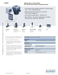
2.2.1. 2/2-way plunger-type<br />
solenoid <strong>valves</strong><br />
Direct-acting 2/2-way plunger-type<br />
solenoid <strong>valves</strong> (e.g. Bürkert Types<br />
6011 and 6013), also referred to as<br />
through-way <strong>valves</strong>, are shut-off <strong>valves</strong><br />
with two ports: one inlet P and one<br />
outlet A, see Figure 1: Inlet P is connected<br />
to the pressurized fluid or gas.<br />
In the de-energized state, the core<br />
spring, assisted by the fluid pressure,<br />
forces the solenoid core (plunger)<br />
with the valve seal onto the valve seat;<br />
passage to outlet A is thus shut-off.<br />
If voltage is applied, the solenoid core<br />
with the valve seal is pulled into the<br />
coil as the result of the magnetic force<br />
and the valve opens; the passage is<br />
unobstructed again.<br />
Characteristics:<br />
■ Flow direction normally above seat<br />
■ The maximum pressure depends<br />
on the nominal diameter and power<br />
consumption of the coil<br />
■ Weak springs in use, i.e. low backpressure<br />
tightness (dependent on<br />
spring force and nominal diameter).<br />
<strong>Solenoid</strong> coil<br />
Electrical connection<br />
Core spring<br />
Core, plunger<br />
Valve seal<br />
Valve seat<br />
P<br />
A<br />
Valve body<br />
Figure 1:<br />
Direct-acting 2/2-way plunger-type solenoid valve,<br />
shown closed at left and open at right<br />
18/19
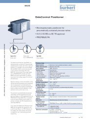
2.2.2. 3/2-way plunger-type<br />
solenoid <strong>valves</strong><br />
Direct-acting 3/2-way plunger-type<br />
solenoid <strong>valves</strong> (e.g. Bürkert Types<br />
6012 and 6014) have three ports and<br />
two valve seats. Alternately, one valve<br />
seat is always open or closed.<br />
The circuit function of the valve depends<br />
on how the ports are “assigned”,<br />
i.e. how they are connected to the fluid<br />
system. In circuit function C (NC),<br />
port P (see Figure 2) is connected to<br />
the supply which ducts pressurized<br />
fluid; port A forms the outlet and port<br />
R is the return or venting port. In the<br />
de-energized state, a conical spring<br />
forces the core (plunger) onto the valve<br />
seat 1 and blocks off supply P. Outlet<br />
A is connected to return R. After energization,<br />
the core is pulled into the solenoid<br />
coil, whereby valve seat 2 is<br />
sealed off via the spring-mounted valve<br />
seal 2. The return R is thus shut-off.<br />
As the plunger moves upwards, valve<br />
seat 1 is also opened and the fluid can<br />
flow from P to A. In circuit function D<br />
(NO), the return R is normally shut-off.<br />
Characteristics:<br />
■ in WW C (NC) flow direction<br />
below valve seat 1<br />
■ in WW D (NO) pressure inlet on<br />
upper valve seat (in diagram, port R,<br />
from the top)<br />
■ Maximum pressure is dependent<br />
on the spring force and the nominal<br />
diameter (not power consumption<br />
of the coil)<br />
■ High spring forces in WW C and<br />
weak spring force in WW D<br />
■ In the case of WW C (NC), the<br />
operating pressure is not limited by<br />
the pick-up force of the coil, but by<br />
the closing force of the conical<br />
spring.<br />
R<br />
Electrical connection<br />
<strong>Solenoid</strong> coil<br />
Valve seat 2<br />
Valve seal 2<br />
Core, plunger<br />
Conical spring<br />
Valve seal 1<br />
Veal seat 1<br />
A<br />
P<br />
Valve body<br />
Figure 2:<br />
Direct-acting 3/2-way solenoid valve,<br />
inlet P closed, outlet A vented to R (left),<br />
inlet P open to outlet A (right)
2.2.3. Direct-acting solenoid <strong>valves</strong>:<br />
pivoted-armature <strong>valves</strong><br />
Pivoted-armature <strong>valves</strong> are used with<br />
a 3/2-way function and in a 2/2-way<br />
version. On the 3/2-way Bürkert pivoted-armature<br />
valve (e.g. Type 0330,<br />
see Figure 3), all three ports are accommodated<br />
in the valve body and an<br />
isolating diaphragm prevents fluid from<br />
entering the solenoid system’s armature<br />
chamber. The pivoted-armature<br />
<strong>valves</strong> are equipped with a manual<br />
override function (standard) and can<br />
also be optionally equipped with a visual<br />
position indicator or an electrical<br />
feedback indicator.<br />
Advantages:<br />
■ Excellent reliability<br />
■ All three fluid ports in one plane<br />
■ Media separation on standard<br />
design<br />
■ Long service life<br />
■ AC, DC and UC versions available<br />
■ Visual or electrical position feedback<br />
optionally available<br />
■ Also available as explosion-proof<br />
version<br />
■ Conditionally suitable for aggressive<br />
media as well<br />
Potential disadvantages:<br />
■ Replacement part exchange<br />
difficult<br />
■ Cost-intensive<br />
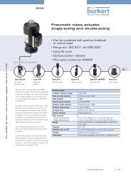
2.2.4. Direct-acting solenoid <strong>valves</strong>:<br />
3/2-way rocker valve<br />
The Bürkert rocker solenoid valve<br />
(Bürkert Types 6104 and 6106) is designed<br />
for operation with compressed<br />
air; all three ports are also accommodated<br />
in the valve body. The valve is<br />
also frequently used as a pilot valve<br />
for pneumatic <strong>valves</strong>. A rocker with<br />
sealing seats alternately closes valve<br />
seats 1 for the air supply (fluid port P)<br />
and 2 for venting (fluid port R) of the<br />
outlet channel (fluid port A) (see Figure<br />
4), in a similar manner to the pivoted-armature<br />
valve. <strong>Solenoid</strong> <strong>valves</strong><br />
with rocker technology are available<br />
with or without isolating diaphragm.<br />
Return<br />
spring<br />
Valve seat 1<br />
P<br />
A<br />
Electrical connection<br />
Manual override<br />
<strong>Solenoid</strong> coil<br />
Core,<br />
pivoted armature<br />
Isolating diaphragm<br />
Valve seat 2<br />
R<br />
Valve body<br />
Advantages:<br />
■ Low mass of moving parts<br />
■ 3 fluid ports in one plane<br />
■ Media-separated version available<br />
■ Economical<br />
■ Very long service life<br />
■ Compact design<br />
■ Low coil power<br />
■ High coil system efficiency<br />
■ Also available as explosion-proof<br />
version (intrinsically safe).<br />
Figure 3:<br />
Bürkert pivoted-armature solenoid valve<br />
20/21
Potential disadvantages:<br />
■ Only DC version, or for AC with<br />
series-connected rectifier (in coil<br />
or appliance plug)<br />
■ Media separation reduces maximum<br />
pressure range<br />
■ Low input pressure (max. 10 bar)<br />
Return<br />
spring<br />
Valve<br />
seat 2<br />
R<br />
A<br />
P<br />
Electrical<br />
connection<br />
<strong>Solenoid</strong> coil<br />
Rocker<br />
Valve seat 1<br />
Valve body<br />
Figure 4:<br />
Rocker valve<br />
2.2.5. Characteristics and possible applications of various solenoid actuators for solenoid <strong>valves</strong><br />
Plunger Pivoted armature Rocker<br />
Media separation No Standard with media Available with and without<br />
in actuator separation. media separation.<br />
Wear behavior/ Moderate to high wear Low wear since there is no Very low wear and long service<br />
service life susceptibility of the solenoid sliding friction in the armature. life (special version without<br />
core due to the friction in<br />
isolating diaphragm).<br />
the core guide tube, depending<br />
on field of application.<br />
Universality and Very robust solenoid coils Very tried and tested actuation Small, compact actuation system,<br />
possible applications available in various sizes principle. Only one coil size particularly as pilot valve or for<br />
and with various power available. low flow rates.<br />
ratings. Can be used for AC/DC/UC. Can be used only for DC,<br />
Can be used for AC/DC/UC.<br />
or also for UC with seriesconnected<br />
rectifier.<br />
Typical media Neutral gaseous and fluid, Neutral gaseous and fluid, Without media separation:<br />
non-abrasive media, e.g. media, conditionally also neutral gases, e.g. air<br />
- Water (demineralized water, aggressive and abrasive,<br />
only conditional) depending on use/usability With media separation:<br />
- Air and resistance of the isolating also aggressive gases and<br />
- Oils diaphragm material, e.g. fluids of low viscosity<br />
- Industrial gases - Water (including<br />
demineralized water)<br />
- Oils, Acids and lyes<br />
- Ultrapure media
2.3.<br />
Servo-assisted<br />
solenoid <strong>valves</strong><br />
At high system pressures and with<br />
large nominal diameters, it would also<br />
be necessary to have higher magnetic<br />
forces and electrical control power<br />
values in direct-acting solenoid <strong>valves</strong>.<br />
The larger solenoid coils required for<br />
this would increase the overall weight<br />
and overall size. Consequently, servoassisted<br />
<strong>valves</strong> are used.<br />
In the case of servo-assisted solenoid<br />
<strong>valves</strong>, a main valve is controlled by a<br />
solenoid-operated pilot valve with<br />
smaller flow cross-sections and lower<br />
electrical control power. This control<br />
can comprise either a 2/2-way pilot<br />
valve or a 3/2-way pilot valve. The main<br />
valve uses a diaphragm or a piston as<br />
a moving closure element for opening<br />
and closing the fluid path.<br />
The Bürkert valve range also includes<br />
servo-assisted solenoid <strong>valves</strong> on which<br />
the armature of the pilot valve is linked<br />
to the piston or diaphragm of the main<br />
valve (forced valve lifting). On these<br />
<strong>valves</strong> (e.g. Bürkert Types 6213 and<br />
290), a minimum pressure differential<br />
is not required. Depending on the design,<br />
a low pressure differential is required<br />
to open the full cross-section.<br />
This principle is used primarily with<br />
2/2-way <strong>valves</strong>, both normally closed<br />
and normally open. The valve can be<br />
operated in only one flow direction.<br />
The back-pressure tightness is very<br />
low.<br />
22/23
2.3.1. Servo-assisted 2/2-way<br />
solenoid <strong>valves</strong> with diaphragm<br />
In this case, a plunger-type solenoid<br />
is used as the pilot valve. The main<br />
valve seat is opened and closed by<br />
means of a diaphragm. With this, closing<br />
is performed both by the force of<br />
the compression spring and by the<br />
medium pressure.<br />
The fluid chamber above the diaphragm<br />
is relieved when the pilot opens. The<br />
medium pressure beneath the diaphragm<br />
lifts the diaphragm and opens<br />
the valve. If the pilot valve is closed,<br />
the medium pressure builds up again<br />
above the diaphragm through a restrictor<br />
port in the diaphragm or through<br />
a bypass channel. The system closes<br />
as the result of the higher area ratio<br />
(above the diaphragm).<br />
The chief application area of servoassisted<br />
diaphragm solenoid <strong>valves</strong><br />
with large nominal diameters (approx.<br />
DN 10 ... 65 mm) relates to neutral<br />
but also aggressive, fluid and gaseous<br />
media. Bürkert units based on this<br />
principle include, for example, Types<br />
5281, 6211, 6228 and 0142.<br />
Advantages:<br />
■ Economical mechanical<br />
construction<br />
■ Low electrical power consumption<br />
■ Good closing-impact damping<br />
■ Low pressure differential required.<br />
Disadvantages:<br />
■ Sensitive to dirty media<br />
■ Not suitable for medium temperatures<br />
> 120 °C<br />
■ Restricted service life if gaseous<br />
media are used.<br />
Compression spring<br />
Diaphragm<br />
Restrictor port<br />
Servo-assisted seat<br />
Figure 5:<br />
Servo-assisted 2/2-way solenoid valve, normally closed, with diaphragm.<br />
Shown closed at left and open at right
2.3.2. Servo-assisted solenoid<br />
<strong>valves</strong> with piston<br />
A plunger-type solenoid is used as the<br />
pilot valve with this principle as well,<br />
but the main valve function is implemented<br />
by a piston. The function of<br />
this valve (e.g. Types 5404 and 6221)<br />
results from the fact that fluid is also<br />
able to flow from the supply P through<br />
a control bore in the piston or bypass<br />
channel of the main valve. If the chamber<br />
above the piston is closed off with<br />
the pilot valve de-energized, the fluid<br />
system pressure builds up there as<br />
well and the piston, which simultaneously<br />
forms the valve seal, closes the<br />
valve seat in the main valve.<br />
It is assumed that the fluid pressure<br />
can be discharged in outlet A. For as<br />
long as a pressure differential exists<br />
between the inlet port and the outlet<br />
port, the main valve remains closed as<br />
the result of the closing forces above<br />
the piston. After activating the pilot<br />
valve, the pressure in the chamber<br />
above the piston is able to drop. The<br />
force acting on the lower side of the<br />
piston as the result of the fluid system<br />
pressure is greater than that on the<br />
upper side of the piston, it lifts the piston<br />
and opens the main valve. Servoassisted<br />
solenoid <strong>valves</strong> operating on<br />
the basis of this design require a minimum<br />
pressure differential for correct<br />
opening and closing. <strong>Solenoid</strong> <strong>valves</strong><br />
with a coupling (forced valve lifting)<br />
between the solenoid core and piston<br />
(e.g. Type 407) require no pressure<br />
differential for switching. Servo-assisted<br />
piston-operated <strong>valves</strong> are used<br />
chiefly in applications with high pressures,<br />
gaseous media and steam up<br />
to 180 °C.<br />
Advantages:<br />
■ More robust than servo-assisted<br />
solenoid <strong>valves</strong> with diaphragm<br />
■ Higher pressure range<br />
■ Suitable for gases and steam.<br />
Disadvantages:<br />
■ More expensive than servo-assisted<br />
solenoid <strong>valves</strong> with diaphragm<br />
■ Less damping of closing impact<br />
■ Require higher pressure differential<br />
for opening.<br />
Electrical<br />
connection<br />
Pilot valve<br />
Return spring<br />
<strong>Solenoid</strong> coil<br />
P<br />
Core, plunger<br />
Piston<br />
Restrictor port<br />
Main valve<br />
Valve body<br />
Valve seat<br />
A<br />
Figure 6:<br />
Servo-assisted 2/2-way solenoid valve, normally closed, with piston.<br />
Shown closed at left and open at right<br />
24/25
2.3.3. Force pilot operated solenoid<br />
<strong>valves</strong><br />
Force pilot operated solenoid <strong>valves</strong><br />
essentially differ from the normal servo-assisted<br />
solenoid <strong>valves</strong> by means<br />
of a coupling, either of the piston or of<br />
the diaphragm, to the solenoid core.<br />
This coupling may either be direct or<br />
comprise a spring.<br />
The function is a combination of directacting<br />
and servo-assisted. In the case<br />
of low pressure differentials, the directacting<br />
function of the system predominates,<br />
and the servo-assisted function<br />
of the system predominates at higher<br />
pressure differentials.<br />
Advantage:<br />
■ Opens without pressure differential,<br />
can also be used in circuits or at<br />
low pressures<br />
■ Good closing-impact damping<br />
■ Good price-performance ratio<br />
■ Universal usability.<br />
Disadvantage:<br />
■ Sensitive to dirty media due to<br />
small diameters of the control bore<br />
in the diaphragm<br />
■ Only normally closed function<br />
available<br />
■ Coils with a higher power rating<br />
are required for larger nominal diameters.<br />
Pilot valve<br />
<strong>Solenoid</strong> coil<br />
Core, plunger<br />
Valve seat, Pilot<br />
Restrictor port<br />
Valve seat<br />
Main valve<br />
A<br />
Figure 7:<br />
Servo-assisted 2/2-way solenoid valve, force pilot operated, normally closed, with diaphragm.<br />
Shown closed at left and open at right
2.3.4. Servo-assisted solenoid<br />
<strong>valves</strong> with 3/2-way pilot<br />
A pivoted-armature or rocker valve<br />
with isolating diaphragm is used as<br />
the pilot valve. The essential difference<br />
with respect to the 2-way pilot is that<br />
a medium does not flow through the<br />
pilot in an open switch position and<br />
thus there is a much slighter risk of<br />
clogged control bores due to dirty<br />
media. In addition, a diaphragm protects<br />
the solenoid armature against<br />
harmful influences.<br />
The chief field of application of this<br />
functional principle (e.g.: Type 142<br />
and Type 5282) therefore obviously<br />
relates to both dirty media and aggressive<br />
media.<br />
Advantages:<br />
■ No small control bores in the diaphragm<br />
and thus less sensitive to<br />
dirty media<br />
■ <strong>Solenoid</strong> chamber protected by<br />
isolating diaphragm<br />
■ Only a small quantity of medium<br />
flows through the pilot valve for<br />
opening or closing<br />
■ No medium flow through the pilot<br />
valve in open condition! This is a<br />
crucial advantage over <strong>valves</strong> with<br />
2-way pilot.<br />
■ Response times adjustable with<br />
adjusting screws<br />
■ NC and NO function, possible simply<br />
by turning the pilot<br />
■ Extremely high functional reliability<br />
■ Also available as explosion-proof<br />
version.<br />
Potential disadvantages:<br />
■ Cost-intensive<br />
■ Cannot be used in all circuits, since<br />
the system requires pressure<br />
differential for opening.<br />
Figure 8:<br />
Media-separated servo-assisted solenoid valve with diaphragm<br />
and 3/2-way pilot solenoid<br />
26/27
3. Basics of dynamic fluid mechanics<br />
3.1.<br />
Flow behavior of solenoid<br />
<strong>valves</strong> for fluidics<br />
3.2.<br />
Flow behavior and k v<br />
value of fluids<br />
3.1.1. Differences with respect to<br />
application areas<br />
In fluidics, solenoid <strong>valves</strong> are chiefly<br />
used as pilot <strong>valves</strong>. These can either<br />
open or close a line (ON/OFF <strong>valves</strong>)<br />
or switch over a material stream from<br />
one line to another. These are tasks of<br />
binary control engineering. Valves<br />
which are able to constantly vary their<br />
opening cross-section are required<br />
for closed-loop control-engineering<br />
tasks (continuous-action <strong>valves</strong>, control<br />
<strong>valves</strong> / proportional <strong>valves</strong>).<br />
When selecting solenoid pilot <strong>valves</strong><br />
for fluidics, the main interest is whether<br />
the required fluid quantity is able to<br />
flow through the valve at the given<br />
pressure differential, i.e. whether the<br />
valve features an adequately large<br />
cross-section and an adequate switching<br />
capacity. In the case of control<br />
<strong>valves</strong>, the shape of the valve characteristic<br />
curves (opening, flow and<br />
operating characteristic curve) is also<br />
of importance.<br />
3.2.1. Volume flow and mass flow<br />
With fluids, the volume flow through a<br />
valve or fitting can generally be calculated<br />
on the basis of the following formula.<br />
· 2 · p<br />
V= · A<br />
<br />
where<br />
=<br />
1<br />
<br />
Where:<br />
Flow coefficient<br />
A: Cross-section<br />
p: Pressure drop through valve<br />
(pressure loss)<br />
: Density of the fluid<br />
: Loss index or resistance index<br />
The following applies<br />
p = 1 – 2<br />
= A<br />
2 · p<br />
· <br />
Equation 1<br />
Pressure drop<br />
through<br />
a valve<br />
Valve<br />
The mass flow can be obtained with<br />
· ·<br />
M = · V:<br />
·<br />
M = · A<br />
2 · · p = A<br />
2 · · p<br />
<br />
Equation 2
3.2.2. k v value<br />
The k v value, which is defined as follows,<br />
has been introduced to describe<br />
the flow behavior of <strong>valves</strong>:<br />
■ The k v value is the volume flow<br />
·<br />
V (in m 3 /h) of water ( 0 =1kg/dm 3 )<br />
at a temperature between 5 and 40<br />
°C at a pressure drop (permanent<br />
pressure loss) at the valve of<br />
0 =100 kPa.<br />
Since the k v value designates a volume<br />
flow (m 3 /h), the frequently encountered<br />
designations “flow-rate coefficient” or<br />
“valve coefficient” are misleading since<br />
they presuppose that k v is non-dimensional.<br />
3.2.3. c v value and Q Nn value<br />
In countries using the Imperial system,<br />
the cv value is used as the flow parameter<br />
instead of the k v value.<br />
From this equation, we can then deduce<br />
the following for the k v value:<br />
k v = · A<br />
2 · p 0<br />
0<br />
Equation 3<br />
For a valve, the k v value can be determined<br />
experimentally on the basis of<br />
the assumptions contained in the definition<br />
( 0 und 0 ). It thus represents<br />
a parameter for characterizing a valve.<br />
Thus, the k v value can initially be used<br />
as a measure of the quality of the flowdynamics<br />
design of <strong>valves</strong>. If, for example,<br />
we compare several <strong>valves</strong><br />
with the same nominal diameter, the<br />
valve with the highest k v value is the<br />
best-designed valve from a flow dynamics<br />
perspective.<br />
■ The c v value is the volume flow (in<br />
US gallons/minute) of water at a<br />
temperature of 60 °F with a pressure<br />
loss of 1 psi through the valve.<br />
Where:<br />
1USgallon/minute = 0.227 m 3 /h and<br />
1 psi = 0.069 bar (psi: pounds per<br />
square inch).<br />
The QNn value, which is defined as<br />
follows, is another flow parameter used<br />
for <strong>valves</strong> in pneumatics. The Q Nn value<br />
is the volume flow (in liters/minute) of<br />
air at a temperature of +20 °C and at<br />
an input pressure of 6 bar and a pressure<br />
drop through the valve of 1 bar.<br />
The following conversion factors apply<br />
for converting k v to c v and Q Nn :<br />
k v = 0.86 c v<br />
k v = 1078 Q Nn .<br />
28/29
3.2.4. Interrelationship between volume<br />
flow and kv value<br />
If we divide equation 3 by equation 1<br />
and reformulate accordingly, we obtain<br />
the following for the volume flow:<br />
· <br />
V = k 0 · p<br />
v<br />
· p 0<br />
The volume flow of any fluid with the<br />
corresponding density (with any pressure<br />
drop ) can be calculated with<br />
equation 4 for a valve with a given k v<br />
value. If we reformulate equation 4<br />
accordingly, it is possible to calculate<br />
the pressure loss at any volume<br />
flow values and with any fluids.<br />
If we substitute the values for 0 and<br />
· ·<br />
p o in equation 4 and if M = V , it is<br />
possible to state the following everyday<br />
formulae for fluids:<br />
Volume flow<br />
· p<br />
V = 100 k v<br />
<br />
Mass flow<br />
·<br />
M = 100 k v<br />
p<br />
On the other hand, the required k v value<br />
can be determined at a given volu-<br />
and p 1 , which can be expressed by<br />
dence on the ratio of the pressure p 2<br />
me flow of any medium and at a given<br />
the outflow function . Thus, the following<br />
initially applies to mass flow:<br />
permitted pressure loss, thus allowing<br />
·<br />
us to establish a suitable valve type.<br />
·<br />
M = · A · 2 · 1 ·p 1<br />
Where:<br />
: Flow coefficient<br />
Everyday formulae for fluids, meaning of symbols<br />
: Outflow function (function of<br />
k v Defined volume flow of water in m 3 /h<br />
·<br />
pressure ratio p<br />
V Volume flow in m 3 2 /p 1 )<br />
/h<br />
·<br />
A: Cross-section<br />
M Mass flow in kg/h<br />
1 : Density of the gas upstream of<br />
p 1 Absolute pressure at valve inlet in MPa<br />
the valve<br />
p 2 Absolute pressure at valve outlet in MPa<br />
p 1 : Pressure of the gas upstream of<br />
p Pressure drop through valve in MPa<br />
the valve<br />
Density in kg/m 3<br />
Table 1<br />
Equation 4<br />
3.3.<br />
Flow behavior with<br />
gases<br />
3.3.1. Mass flow and volume flow<br />
with gases<br />
The relationships stated for fluids can<br />
also be applied to gases provided the<br />
differences resulting from compressibility<br />
and the special aspects of subcritical<br />
and super-critical outflow applicable<br />
to gases are allowed for.<br />
In the case of fluids, both the volume<br />
flow V and the mass flow M can be<br />
stated as a function of the pressure<br />
drop p = p 1 - p 2 through the valve,<br />
i.e. as a function of the pressure differential<br />
(equations 1 to 4). By contrast,<br />
in the case of gases, there is a depen-<br />
Equation 5
Specific values of certain media<br />
Type of gas p 2 max.<br />
Diatomic gases, e.g. N 2 , O 2 , and CO 1.400 0.528 0.484<br />
Air 1.402 0.53 0.49<br />
Triatom. gases, e.g. CO 2 ; superheat. steam 1.300 0.546 0.473<br />
Sattdampf 1.135 0.577 0.45<br />
Table 2<br />
(Konstante)<br />
( p 1<br />
)<br />
A corresponding relationship can also Outflow function <br />
be stated for the volume flow.<br />
If we reduce the pressure ratio p 2 /p 1<br />
crit<br />
3.3.3. Sub-critical and super-critical<br />
outflow<br />
On the basis of this ratio, a distinction<br />
is made in regards to the outflow behavior<br />
of gases in <strong>valves</strong> between a<br />
sub-critical outflow and a super-critical<br />
outflow:<br />
p 2<br />
><br />
p 1 (<br />
p 2<br />
p 1)<br />
crit<br />
3.3.2. Outflow function and critical<br />
pressure ratio<br />
Figure 9 shows as a function of the<br />
pressure ratio p 2 /p 1 . In addition, is<br />
slightly dependent on the adiabatic<br />
exponent which must be entered as<br />
a parameter. is a constant for a specific<br />
ideal gas (see Table 2).<br />
Figure 9<br />
0,6<br />
0,5<br />
0,4<br />
0,3<br />
0,2<br />
0,1<br />
1,6<br />
1,4<br />
1,2<br />
1,0<br />
0,527<br />
0,484<br />
0,459<br />
0,429<br />
0<br />
0,2 0,3 0,4 0,5 0,6 0,7 0,8 0,9 1,0<br />
starting from value 1, i.e. reduce p 2<br />
with constant pressure p 1 , and thus<br />
M, initially rises. Starting at a specific<br />
pressure ratio which is referred to as<br />
the “critical pressure ratio”, the outflow<br />
function and thus also the<br />
mass flow remain constant ( max and<br />
M max ). The critical pressure ratio is<br />
calculated as follows:<br />
p<br />
(<br />
2<br />
p 1<br />
) (<br />
krit<br />
In addition to the adiabatic exponent<br />
, Table 2 shows the critical pressure<br />
ratios and values of max for certain<br />
gases. max may assume values between<br />
0.5 and 0.6 for popular media.<br />
The critical pressure ratios lie approximately<br />
between 0.45 and 0.55. For<br />
practical tasks, it suffices to use a critical<br />
pressure ratio of<br />
(p 2 = 1/2p 1 ).<br />
=<br />
p<br />
(<br />
2<br />
≈ 0,5<br />
p 1<br />
)<br />
crit<br />
<br />
2 -1<br />
<br />
·<br />
+1)<br />
Equation 6<br />
= Sub-critical outflow,<br />
p 2<br />
≤<br />
p 1 (<br />
p 2<br />
p 1)<br />
crit<br />
= Super-critical outflow.<br />
The differences between sub-critical<br />
and super-critical outflows are shown<br />
While, in the case of sub-critical outflow,<br />
the mass flow can be calculated<br />
on the basis of equation 5, in the case<br />
of super-critical outflow, this equation<br />
can be specified more precisely as<br />
follows:<br />
·<br />
M = · A · max 2 · 1 · p 1<br />
Equation 7<br />
By way of approximation, we can use<br />
a value of 0.5 for max .<br />
30/31
If we divide equation 5 or equation 7<br />
by equation 1, which describes the k v<br />
value, and reformulate accordingly, we<br />
obtain the following relationships for<br />
calculating the mass flow of gases<br />
from the k v value:<br />
·<br />
M = k v · <br />
for sub-critical outflow<br />
Sub-critical<br />
outflow<br />
p 1 ; p 2<br />
p 1<br />
Super-critical<br />
outflow<br />
p 1 ; p 2<br />
p 1<br />
0 · 1 · p 1<br />
p 0<br />
Equation 8<br />
p 2<br />
Stream bursts open<br />
p 2<br />
· 0 · 1 · p 1<br />
M = k v · max<br />
p 0<br />
for super-critical outflow.<br />
Thus, using equations 8 and 9, it is<br />
also possible to calculate the mass<br />
flow values or volume flow values of<br />
gases from the k v values.<br />
· ·<br />
M < M max<br />
( < max )<br />
· ·<br />
M < M max<br />
( < max )<br />
p<br />
(<br />
2<br />
p 1a )<br />
p p<br />
(<br />
2<br />
) (<br />
2<br />
)<br />
p p 1crit 1a<br />
p<br />
(<br />
2<br />
) p 1crit<br />
Equation 9<br />
p 2<br />
p 1<br />
p 2<br />
p 1<br />
3.3.4. Everyday formulae for mass<br />
flow and volume flow with gases<br />
From a practical standpoint, various<br />
correction factors which, among other<br />
things, are also intended to allow for<br />
flow of viscous fluids have been introduced<br />
in the formulae for mass flow<br />
and volume flow in the case of gases.<br />
Meaning of symbols:<br />
k v : Defined volume flow in m 3 /h<br />
V: Volume flow of gases in m 3 /h<br />
(at 0.1 MPa and 20 °C)<br />
M: Mass flow in kg/h<br />
p 1 : Absolute pressure at valve<br />
inlet in MPa<br />
p 2 : Absolute pressure at valve<br />
outlet in MPa<br />
p: Pressure drop through valve in<br />
MPa<br />
: Density of gases in kg/m 3 (at<br />
0.1 MPa and 20 °C); v2 specific<br />
volume at p2 in m 3 /kg<br />
v k : Specific volume at p1/2 in<br />
m 3 /kg;<br />
T: Absolute temperature at valve<br />
inlet in K.<br />
Figure 10: Sub-critical behavior and super-critical outflow<br />
Everyday formulae for gases and steam<br />
Gases<br />
Steam<br />
Mass flow Volume flow Mass flow<br />
sub-critical<br />
super-critical<br />
· pp 2<br />
· p ·p<br />
· p<br />
M = 5140 k v V = 5140 k<br />
T<br />
v M = 100 k<br />
T<br />
v<br />
· <br />
· 1<br />
· p<br />
M = 2750 k v p 1 V = 2750 k<br />
T<br />
v p 1 M = 100 k<br />
1<br />
v<br />
T<br />
2v k<br />
v 2
3.4.<br />
Opening and closing<br />
operations in pipes<br />
with fluids<br />
p R<br />
Pressure waves<br />
a<br />
a<br />
Valve upstream pressure<br />
p R bei w = 0<br />
p F bei w 1<br />
3.4.1. Origination and propagation<br />
of pressure waves<br />
If the velocity of a fluid stream in a pipe<br />
changes as the result of opening or<br />
closing a valve, it results in a conversion<br />
of the kinetic energy of the fluid<br />
into a pressure wave which is propagated<br />
from the valve at the propagation<br />
speed “a” of the flow medium against<br />
the flow direction (Figure 11), until<br />
reaching the tank or vessel outlet<br />
(deflection point) where it is reflected<br />
again, etc. This results in pressure undershoots<br />
and overshoots which are<br />
referred to as suction surges and<br />
pressure surges or “water hammer<br />
phenomena”.<br />
In the case of compressible fluids, the<br />
propagation speed “a” of pressure<br />
and velocity changes is equal to the<br />
speed of sound a in the medium in<br />
question.<br />
Speed of sound “a” for fluids in thickwalled,<br />
rigid pipes:<br />
Where:<br />
E: Modulus of elasticity of the<br />
medium in N/m 2<br />
: Density of the medium.<br />
w 0<br />
w 1<br />
L<br />
Figure 11:<br />
Basic mechanical construction of a simple pipe run system<br />
a =<br />
E<br />
<br />
[m/s]<br />
Speed of sound “a” for fluids in thinwalled,<br />
flexible pipes:<br />
E F 1<br />
a = · [m/s]<br />
1+ D·E F<br />
S·E R<br />
w 0<br />
w 1<br />
Unobstracted outlet<br />
The following approximate values can<br />
be assumed for the speed of propagation<br />
or speed of sound in water:<br />
Thick-walled metal pipes: a ≈ 1300 m/s<br />
Thin-walled pipes: a ≈ 1000 m/s.<br />
Equation 10<br />
Where:<br />
D: Pipe diameter<br />
S: Wall thickness<br />
E F : Modulus of elasticity of the<br />
fluid<br />
E R : Modulus of elasticity of the<br />
pipe material.<br />
32/33
3.4.2. Opening and closing times of<br />
solenoid <strong>valves</strong> (response times)<br />
The magnitude of the suction or pressure<br />
surges also depends on the opening<br />
or closing times of the <strong>valves</strong>.<br />
Opening time t op of solenoid <strong>valves</strong> is<br />
determined by the time which elapses<br />
up to the build-up of the magnetic field<br />
after switching on the coil voltage and<br />
by the mass inertia of the valve piston<br />
with the solenoid core. Closing time t cl<br />
depends on the magnetic inertia of<br />
the solenoid system, the mechanical<br />
inertia and the spring force on the<br />
core or armature, as well as on fluidic<br />
influences, such as the type of medium<br />
(fluid or gaseous) and viscosity.<br />
In the following two sections focusing<br />
on the origination of suction and pressure<br />
surges, we initially assume that<br />
the solenoid <strong>valves</strong> open and close at<br />
time t = 0. On the basis of this, an estimate<br />
is provided in each case as to<br />
how the definitive opening and closing<br />
times affect the magnitude of the suction<br />
and pressure surges.<br />
3.4.3. Origination of suction surges<br />
with fluids<br />
If a shut-off line which is pressurized<br />
at pressure p (idle pressure p R in<br />
Figure 11) is suddenly opened at one<br />
end, in time t op =0, the fluid discharges<br />
at the following velocity after opening:<br />
w 0 = p<br />
a · <br />
Where:<br />
w 0 : Velocity after opening of the<br />
valve in time t=0<br />
p: Pressure before opening<br />
: Density of the fluid<br />
a: Propagation speed of the<br />
pressure waves.<br />
Directly after opening of the valve, a<br />
sudden pressure drop occurs, which<br />
is referred to as a “suction surge” or<br />
“negative pressure surge”. This suction<br />
surge results in a “partial vacuum<br />
wave” which is propagated at the<br />
speed of sound from the valve inlet<br />
against the flow direction. At all points<br />
covered by the partial vacuum wave,<br />
the fluid initially moves at velocity w0,<br />
while it is at rest at all other positions<br />
of the pipe run in the propagation direction<br />
in front of the wave front. The<br />
pressure wave is reflected at the tank<br />
outlet, moves back to the valve inlet<br />
and is reflected again there, etc. With<br />
these wave movements, the outflow<br />
velocity increases gradually until, ultimately,<br />
the maximum velocity w1 is reached<br />
at stationary outflow, which can<br />
be calculated on the basis of the following<br />
formula:<br />
w 1 =<br />
Where:<br />
w 1 : Velocity with stationary outflow<br />
p:<br />
2 · p<br />
<br />
Pressure before opening<br />
: Density of the fluid.
A suction surge that is produced by a<br />
sudden opening of a valve in time<br />
t op = 0 reduces the medium pressure<br />
at maximum down to 0 bar. The suction<br />
surge thus cannot increase above<br />
the actual opening pressure or idle<br />
pressure. Consequently, the suction<br />
surge does not generally contribute in<br />
the same way to causing noise and increasing<br />
the pressure stressing of the<br />
system as does a pressure surge which<br />
may reach many times the operating<br />
pressure (idle pressure).<br />
Idle pressure p R<br />
Suction surge<br />
Opening operation<br />
Flow pressure p F<br />
Closing operation<br />
Idle pressure p R<br />
Figure 12: Valve upstream pressure as a function of time<br />
when opening or closing the valve<br />
Pressure surge (water hammer) <br />
Characteristic with no<br />
water hammer<br />
Total pressure<br />
A finite opening time of the valve<br />
(t op > 0) means that the pressure<br />
waves are not produced to full strength<br />
and that the suction surge cannot, in<br />
practical terms, reach the maximum<br />
value, i.e. the operating pressure (see<br />
Figure 12).<br />
3.4.4. Origination of pressure surges<br />
(water hammer phenomena)<br />
with fluids<br />
If the valve is suddenly closed (closing<br />
time t cl = 0) with stationary outflow at<br />
velocity w 1 and if the pipe run is thus<br />
completely shut off, the fluid column is<br />
abruptly decelerated from w 1 to w = 0.<br />
This produces a pressure wave which<br />
passes through the medium against<br />
the flow direction at the speed of<br />
sound “a”. The pressure wave is reflected<br />
at the tank outlet (see Figure 11),<br />
moves back to the valve inlet and is<br />
reflected there again, etc. Superimposition<br />
of the pressure waves against<br />
the flow direction and the reflected<br />
pressure waves results in pressure<br />
piling, the maximum value of which<br />
can be calculated in accordance with<br />
the following equation:<br />
Where:<br />
p max : Pressure directly after closing<br />
the valve<br />
a: Speed of propagation or sound<br />
: Density of the fluid<br />
w 1 : Velocity with stationary outflow<br />
This pressure piling in accordance with<br />
equation 10 is referred to as pressure<br />
surge or water hammer. It can be many<br />
times the operating pressure and can<br />
thus lead to bothersome noises and,<br />
above all, increased pressure stressing<br />
of the system.<br />
p max = a · · w 1<br />
Equation 10<br />
34/35
The maximum value p max of the pressure<br />
surge is reduced if closing time<br />
t cl of the valve is longer than the wave<br />
propagation time T L from the valve to<br />
the first pressure wave reflection point<br />
(tank outlet in Figure 11) and back, i.e.<br />
if the following applies:<br />
The impact number is defined only in<br />
the range of 0 < Z < 1.<br />
Z=1fort cl T L<br />
Condition 1<br />
0.5<br />
If we designate the distance between<br />
valve and first reflection point (see<br />
Figure 11) as L, we can calculate the<br />
wave propagation time T L as follows:<br />
0<br />
Impact number<br />
0.5 1.0 1.5<br />
T L<br />
t cl<br />
T L =<br />
2L<br />
a<br />
If condition 1 is met, the pressure<br />
waves are unable to develop to full<br />
strength. This also results in a dependence<br />
of the pressure surge p in accordance<br />
with equation 11 on the ratio<br />
T L to t cl . This ratio is referred as the<br />
impact number Z<br />
Z= T L<br />
t cl<br />
Equation 11<br />
This results in the following everyday<br />
formula for calculating pressure surges<br />
in the case of fluids:<br />
p = Z · a · · w 1<br />
Where:<br />
p: Pressure directly after closing<br />
the valve<br />
a: Speed of propagation or sound<br />
: Density of the fluid<br />
w 1 : Velocity with stationary outflow<br />
Z: Impact number (see Figure 13)
3.4.5. Example calculation<br />
The flow velocity gradually increases<br />
The resultant velocities and pressures from 10 m/s to the outflow velocity<br />
when suddenly opening and closing a with stationary outflow, which can be<br />
pipe run will be demonstrated by way calculated in accordance with equation<br />
13, only when the pressure waves<br />
of example.<br />
moving back and forth in the pipe<br />
Problem<br />
have receded.<br />
There is a tank containing pressurized<br />
water at the start of a pipe and a<br />
2 · p 2 · 100 · 10 5<br />
w<br />
pressure of<br />
1 = = ≈ 140 m/s<br />
<br />
10 3<br />
100 bar = 100 · 10 5 N/m 2 prevails in<br />
the tank (see Figure 11). At the end of<br />
the pipe, there is a solenoid valve If the valve is suddenly closed again in<br />
which suddenly opens or closes the time t = 0 with stationary outflow, the<br />
entire pipe cross-section in time t = outflow velocity is reduced from<br />
0. A speed of sound of a ≈ 1000 m/s 140 m/s to zero. In this case, a pressure<br />
rise as follows is produced in ac-<br />
is assumed. The density is =10 3<br />
kg/m 3 .<br />
cordance with equation 14:<br />
Directly after opening, the water flows<br />
out of the valve at the following velocity,<br />
in accordance with equation 12: This would be 14 times the pressure<br />
originally applied to the start of the<br />
100 · 10 5<br />
pipe. This value applies to t cl < T L . If<br />
w 0 = 10 m/s<br />
10 3 · 10 3 closing time t cl is, for example, twice<br />
Equation 12 as low as the pressure wave propagation<br />
time T L , the pressure rise would<br />
The pressure at the valve suddenly only be half as high, e.g. 700 bar.<br />
drops from 100 bar to zero in this case.<br />
The wave of the pressure gradient of<br />
-100 bar moves at the speed of sound<br />
to the start of the pipe A and reaches<br />
it after L/a s, so that the water here as<br />
well now also starts to flow at 10 m/s.<br />
Equation 13<br />
p=a· ·w 1 =10 3 ·10 3 · 140 = 1400 · 10 3 N/m 2 = 1400 bar<br />
Equation 14<br />
36/37
3.4.6. <strong>Solenoid</strong> <strong>valves</strong> with adjustable<br />
closing time and opening time<br />
(response times)<br />
In order to keep pressure surges within<br />
limits, it must be ensured that the<br />
closing times of <strong>valves</strong> are not too<br />
short. Valves with adjustable closing<br />
times that can thus be adapted to the<br />
relevant problem, including Bürkert<br />
valve Type 5282, are advantageous.<br />
On this valve, the closing time can be<br />
set with a restrictor adjusting screw.<br />
With servo-assisted 2/2-way solenoid<br />
<strong>valves</strong>, the closing and opening movement<br />
is damped. The opening and<br />
closing times are determined in this<br />
case by the size of the restrictor ports<br />
in the supply and discharge of the<br />
pre-chamber compartment. The smaller<br />
the control bore, the slower the<br />
valve will close. On the basis of this<br />
interrelationship, it is possible to manufacture<br />
solenoid <strong>valves</strong> with adjustable<br />
closing times. They generally feature a<br />
constant discharge cross-section and<br />
a supply port which can be adjusted<br />
by means of a screw.<br />
Further damping of the water hammer<br />
phenomenon can be achieved by design<br />
and geometrical shaping of a<br />
damping cone, e.g. the diaphragm<br />
support on diaphragm <strong>valves</strong>.
4. Materials for Bürkert solenoid <strong>valves</strong><br />
The materials for body, seals and actuator<br />
are selected and intermatched to<br />
produce optimum products in regards<br />
to functional reliability/safety, fluid<br />
compatibility, service life and economy.<br />
Basically, the materials listed in the<br />
table below, with the material properties<br />
shown, are available. The available<br />
materials can be taken from the relevant<br />
data sheet for the solenoid valve.<br />
Materials Code<br />
General chemical resistance Permissible temperatures<br />
Coil materials<br />
Neutral media<br />
constant<br />
Neutral media<br />
short-term<br />
Aggressive media<br />
constant<br />
Epoxy resin EP Resistant to virtually all chemicals. -20 °C to<br />
Not resistant to low-molecular organic +150 °C<br />
acids in high concentration and highly<br />
oxidizing substances.<br />
Polyamide PA See Body materials (plastics)<br />
Seal and diaphragm materials<br />
Ethylene-propylene- EPDM (A) Good resistance to ozone and weathering, -30 °C to Dependent<br />
rubber particularly suitable for aggressive +130 °C on the agchemicals.<br />
Unfavorable for oils and<br />
gressiveness<br />
greases.<br />
of the medium<br />
and the<br />
mechanical<br />
load<br />
Fluorinated rubber FPM (F) The chemical properties are the most -10 °C to -10 °C to<br />
(FKM) favorable of all elastomers. +150 °C +200 °C<br />
Nitrite rubber NBR (B) Good resistance to oil and petrol. -10 °C to -10 °C to<br />
Unfavorable for oxidizing media. +90 °C +120 °C<br />
Chloroprene rubber CR (N) The chemical properties are very similar -10 °C to -10 °C to<br />
(neoprene) to those of PVC and lie between those of +100 °C +110 °C<br />
NBR and EPDM.<br />
Perfluorinat. rubber FFKM Similar to PTFE -10 °C to to<br />
FFKM, FFKM (dependent on blend) +260 °C +320 °C<br />
(FFKM only)<br />
Chemraz +230 °C<br />
Polytetrafluor- PTFE (E) See Body material (plastics)<br />
ethylene<br />
Steel 1.4112 -20 °C to -20 °C to<br />
+450 °C +150 °C<br />
38/39
Materials<br />
Code<br />
General chemical resistance<br />
Permissible temperatures<br />
Metals for bodies<br />
Neutral media<br />
constant<br />
Neutral media<br />
short-term<br />
Aggressive media<br />
constant<br />
Stainless steel See resistance tables -20 °C to -20 °C to<br />
+400 °C +150 °C<br />
1.4401 Also 1.4404, 1.4408, 1.4409, 1.44010<br />
1.4571 Also 1.4581<br />
1.4305 Also 1.4301, 1.4303<br />
1.4104 Also 1.4105<br />
Gray cast iron GG 25 For neutral media -20 °C to<br />
+180 °C<br />
Spheroidal GGG 40.3 For neutral media -20 °C to<br />
graphite steel +400 °C<br />
Cast steel GS - C For neutral media -20 °C to<br />
C22, C25 +400 °C<br />
Brass MS See resistance tables -20 °C to<br />
+250 °C<br />
Red bronze RG See resistance tables -20 °C to<br />
+250 °C<br />
Plastics for bodies<br />
Polyvinyl chloride, PVC Resistant to most acids, lyes and saline 0 °C to 0 °C to 0 °C to<br />
rigid solutions +60 °C +60 °C +40 °C<br />
PVC-HT 0 °C to 0 °C to 0 °C to<br />
chlor.PVC +90 °C +110 °C +40 °C<br />
Polypropylene PP Resistant to aqueous solutions of acids, 0 °C to 0 °C to<br />
Polyethylene PE lyes and salts and a large number of +100 °C +60 °C<br />
organic solvents.<br />
Unsuitable for concentrated, oxidizing<br />
acids.<br />
Polyamide PA Resistant to oils, greases, waxes, fuels, 0 °C to 0 °C to<br />
weak alkalis, aliphatic and aromatic +100 °C +60 °C<br />
hydrocarbons.<br />
Polytetrafluor- PTFE Resistant to virtually all chemicals. -20 °C to -20 °C to -20 °C to<br />
ethylene Not resistant to liquid sodium and +200 °C +260 °C +150 °C<br />
fluorine compounds.<br />
Polyvinylidene PVDF Not resistant to hot solvents or ketone, -20 °C to<br />
fluoride ester and strong alkaline solutions. +100 °C<br />
Polyphenyl sulfide PPS Resistant to diluted mineral acids, lyes, to +200 °C to +260 °C<br />
aliphatic and aromatic hydrocarbons,<br />
oils and greases, water, hydrolysisresistant.<br />
Polyether ether PEEK Resistant to most chemicals. to +250 °C to +300 °C<br />
keton<br />
Not resistant to concentrated sulfuric<br />
acid, nitric acid and certain halogenated<br />
hydrocarbons.
5. Approvals<br />
In order to ensure the free exchange<br />
of products on the European market<br />
and guarantee that <strong>valves</strong> do not pose<br />
a risk during operation, operational<br />
safety for the operator and protection<br />
for the environment is required in valve<br />
technology as well.<br />
Over the course of the years, individual<br />
directives and national standards have<br />
resulted in clear standards that have<br />
been implemented in national or international<br />
law by the legislature. These<br />
recognized regulations ensure that<br />
■ equipment items from different<br />
countries are compatible<br />
■ that manufacturers adhere to a set<br />
of regulations regarding design<br />
and production.<br />
These regulations relate to the following<br />
aspects:<br />
■ Protection against risks and dangers<br />
■ Interfaces between technical systems<br />
■ Testing and inspections of products<br />
■ Clear description of the content<br />
and the characteristics of products.<br />
Legal supervisory authorities require<br />
that system operators use only equipment<br />
which meets the necessary safety<br />
requirements pursuant to these regulations.<br />
Within its range of <strong>valves</strong>,<br />
Bürkert has a large number of <strong>valves</strong><br />
which have been granted the corresponding<br />
approvals both nationally<br />
and internationally.<br />
We shall briefly outline the approvals<br />
and their content in the following.<br />
Please refer to the separate “Approvals”<br />
brochure for more detailed information.<br />
5.1.<br />
European explosion<br />
protection<br />
ATEX Directives<br />
(formerly Explosion-Protection (EX)<br />
Directives)<br />
The Atex Directive covers equipment,<br />
components and protection systems<br />
for use in hazardous areas. It also applies<br />
to safety facilities outside of hazardous<br />
areas if they are required for<br />
safe operation of equipment in the hazardous<br />
area with respect to the risk<br />
of explosion.<br />
Content:<br />
■ Applies to mining and all other<br />
hazardous areas<br />
■ Standard for fundamental safety<br />
requirements<br />
■ Applies to complete protection<br />
systems<br />
■ Applies to dust explosion<br />
protection<br />
■ Classification of the devices into<br />
given categories which, in turn,<br />
may be used in the corresponding<br />
zones<br />
■ Manufacturers’ quality systems<br />
must comply with the precise<br />
targets and must be certified by an<br />
appointed testing facility<br />
■ Identification with CE mark and<br />
testing facility number<br />
■ Inclusion of non-electrical equipment<br />
in this scope of validity.<br />
40/41
5.2.<br />
International<br />
explosion-protection<br />
approvals:<br />
In addition to the European and North<br />
American explosion-protection approvals,<br />
Bürkert also has approvals in<br />
many other countries. Some examples:<br />
■ Several Eastern European countries,<br />
such as Poland, the Czech Republic,<br />
Slovakia, Hungary, Croatia and<br />
Russia<br />
■ Japan<br />
■ Australia.<br />
5.3.<br />
National approvals<br />
National approvals are approvals for<br />
which no European Directives are yet<br />
available. A few examples concerning<br />
the use of solenoid <strong>valves</strong> can be<br />
found below:<br />
5.3.1. VDE approval as water valve<br />
for domestic use<br />
The most important requirements are:<br />
■ Electrical safety requirements<br />
■ Stipulated function behavior<br />
■ Compliance with the maximum<br />
stipulated water hammer<br />
■ Tightness<br />
■ Mechanical strength of the fluidic<br />
components.<br />
5.3.2. KTW Recommendations<br />
(Plastics in Drinking Water)/W270<br />
DVGW:<br />
The KTW Recommendation is also required<br />
for the use of solenoid <strong>valves</strong><br />
with VDE approval in the drinking water<br />
sector. The hygiene requirement<br />
applicable to non-metallic materials<br />
(e.g. elastomer seal materials) which<br />
come into contact with the medium is<br />
taken as a basis for this recommendation<br />
in accordance with the specification<br />
of the competent Federal Agency.<br />
5.3.3. Approval as safety shut-off<br />
valve<br />
The European Standard EN 264 “Safety<br />
Shut-Off Devices for Combustion<br />
Plants using Liquid Fuels” is specified<br />
as the test regulation for this. A test<br />
laboratory (e.g. the German Technical<br />
Inspection Authority – TÜV) draws up<br />
a report on the requirements, such as:<br />
■ Stipulated function behavior<br />
■ Continuous loading capability<br />
■ Electrical safety requirements<br />
■ Tightness<br />
■ Mechanical strength of the fluidic<br />
components.<br />
A test number is then issued by DIN<br />
CERTCO. The product is thus registered.
5.4.<br />
European approvals<br />
The European approvals and CE mark<br />
must be considered in conjunction<br />
with one another. Since the products<br />
with CE marking comply with the specified<br />
safety regulations, these marked<br />
products must be accepted in all EU<br />
and EFTA states. A distinction is made<br />
between the regulated and unregulated<br />
area.<br />
Certified quality system<br />
Approval of the quality system used is<br />
performed, depending on the scope,<br />
in accordance with Standards ISO<br />
9000 – 9004. ISO 9001 covers the<br />
quality system from development to<br />
products and up to final inspection of<br />
the products.<br />
In the regulated area, the requirement<br />
stipulates that an independent body<br />
must conduct an EC type examination.<br />
The following directives may apply to<br />
Bürkert, depending on the particular<br />
application:<br />
■ Pressure Equipment Directive<br />
■ Gas Appliances Directive<br />
■ ATEX Directive.<br />
In the unregulated area, it is the manufacturer’s<br />
direct responsibility to attach<br />
the CE mark. In this case, a Declaration<br />
of Conformity may be required of the<br />
manufacturer, specifying the standards<br />
applied. Depending on the particular<br />
application, the following directives<br />
may apply to Bürkert:<br />
■ Low Voltage Directives<br />
■ Electromagnetic Compatibility<br />
Directive<br />
■ Vehicle Directives<br />
■ Medical Device Directives.<br />
5.4.1. Existing approvals at Bürkert<br />
In the regulated area, Bürkert offers<br />
devices<br />
■ with EEx approval<br />
■ in accordance with the Pressure<br />
Equipment Directives<br />
■ in accordance with the Gas<br />
Appliances Directives.<br />
Unregulated area<br />
The CE mark on Bürkert devices refers<br />
to<br />
■ Electromagnetic compatibility in<br />
the areas<br />
■ Low Voltage Directive with the following<br />
limits:<br />
75 - 1500 V for DC voltages<br />
50 - 1000 V for AC voltages<br />
■ Pressure Equipment Directive.<br />
42/43
5.5.<br />
North American<br />
approvals<br />
5.6.<br />
International<br />
approvals<br />
LISTED<br />
These apply to the USA and Canada.<br />
The American Occupational Safety<br />
and Health Administration (OSHA)<br />
drew up the OSHA Regulation. In<br />
Standard 29 CFR, the requirement for<br />
electrical installations or equipment<br />
stipulates that only installations or<br />
equipment which have been tested for<br />
the specified safety requirements by<br />
an NRTL (National Registered Test<br />
Laboratory) may be installed. The<br />
NRTLs specified include the following:<br />
■ Underwriters’ Laboratories (UL),<br />
with 3 different types of approval:<br />
UL-listed<br />
UL-recognized<br />
UL-classified<br />
■ Factory Mutual (FM)<br />
■ Canadian Standards Association<br />
(CSA).<br />
European Directives are being increasingly<br />
recognized and prescribed in<br />
Eastern Europe.<br />
Bürkert has been granted this approval<br />
and offers to serve as an agent for<br />
other companies. The complete CSA<br />
approval, from the measurements to<br />
be carried out up to preparation of the<br />
documents can be conducted by<br />
Bürkert.
6. From the application to<br />
the right product:<br />
6.1. Water and other neutral media<br />
Bürkert 2/2-way and 3/2-way solenoid <strong>valves</strong> for water and other neutral media<br />
Circuit function<br />
Function<br />
Body<br />
material<br />
Seal material<br />
2/2-way NC (A)<br />
2/2-way NO (B)<br />
3/2-way NC (C)<br />
3/2-way NO (D)<br />
Universal distributor/<br />
collector(E/F/T)<br />
direct-acting<br />
servo-assisted<br />
force pilot operated<br />
Brass<br />
Stainless steel<br />
Plastic<br />
NBR<br />
EPDM<br />
FPM<br />
PTFE<br />
Port connections<br />
Optional Ex version<br />
Note<br />
• • • • • Flange media-separated Type 6124<br />
• • • • • • • Flange media-separated Type 6126<br />
• • • • • • • • M5, G/NPT/RC 1/8 Type 6011<br />
Flange<br />
• • • • • • Flange, G/NPT/RC 1 media-separated Type 6128<br />
• • • • • • • • • • • G/NPT/RC 1/4 • media-separated Type 0330<br />
Flange Type 0331<br />
• • • • • • • • G/NPT/RC 1/8, 1/4 • Type 6013<br />
Flange<br />
• • • • • • G/NPT/RC 1/8, 1/4 Type 0211B<br />
• • • • • • • • G/NPT/RC 1/4, 3/8, • Type 0255<br />
1/2<br />
• • • • • • • • G/NPT/RC 1/4, 3/8, • Type 0256<br />
1/2<br />
• • • • • • • G/NPT/RC 1/4 - 1 Type 6211<br />
• • • • • • • • • G/NPT/RC 1/4 - 1 media-separated Type 6212<br />
• • • • • • • G/NPT/RC 1/4 - 2 Type 6213<br />
• • • • Hose butt-mountable Type 6227<br />
G3/8, G3/4<br />
• • • • • • G/NPT/RC 3/8, 1/2 Type 6228<br />
• • • • • • G/NPT/RC 3/8 - 2 1/2, • Type 5281<br />
Flange<br />
• • • • • • G/NPT/RC 3/8 - 2 1/2, Type 0281B<br />
Flange<br />
• • • • • • • • G/NPT/RC 1/2 - 2 1/2, • media-separated Type 5282<br />
Flange<br />
• • • • • • • 1/2 -2”, Flange (GG) Type 0290<br />
• • • • • G/NPT 3/8 - 1 1/2 • Type 0340<br />
44/45
Pressure range (bar)<br />
vac up to 1 up to 2 up to 3 up to 5 up to 10 up to 16up to 25 upto100<br />
Nominal size in mm<br />
0.6<br />
0.8<br />
1.0<br />
1.2<br />
1.6<br />
2.0<br />
2.4<br />
2.5<br />
3.0<br />
4.0<br />
5.0<br />
6.0<br />
8.0<br />
10.0<br />
12.0<br />
13.0<br />
20.0<br />
25.0<br />
32.0<br />
40.0<br />
50.0<br />
65.0<br />
Type 6124<br />
Type 6126<br />
Type 6011<br />
Type 6128<br />
Type 0330<br />
Type 0331<br />
Type 6013<br />
Type 0211B<br />
Type 0255<br />
Type 0256<br />
Type 6211<br />
Type 6212<br />
Type 6213<br />
Type 6227<br />
Type 6228<br />
Type 5281<br />
Type 0281B<br />
Type 5282<br />
Type 0290<br />
Type 0340
6.2. The right product<br />
for neutral gaseous media<br />
Bürkert 2/2-way and 3/2-way solenoid <strong>valves</strong> for neutral gaseous media<br />
Circuit function<br />
Function<br />
Body<br />
material<br />
Seal material<br />
2/2-way NC (A)<br />
2/2-way NO (B)<br />
3/2-way NC (C)<br />
3/2-way NO (D)<br />
Universal distributor/<br />
collector (E/F/T)<br />
direct-acting<br />
servo-assisted<br />
force pilot operated<br />
Brass<br />
Stainless steel<br />
Plastic<br />
NBR<br />
EPDM<br />
FPM<br />
PTFE/FFKM<br />
Port connections<br />
Optional Ex version<br />
Note<br />
• • • • • Flange • Also with Type 6104<br />
manual override<br />
• • • • • • Flange • Also with Type 6106<br />
manual override<br />
• • • • • M5, G/NPT/RC 1/8 Type 6011<br />
Flange<br />
• • • • • • M5, G/NPT/RC 1/8 Also with Type 6012<br />
Flange<br />
manual override<br />
• • • • • • • G/NPT/RC 1/8, G1/4 • Also DVGW Type 6013<br />
Flange<br />
• • • • • • G/NPT/RC 1/8, G1/4 Type 0211B<br />
• • • • • • • • G/NPT/RC 1/8, G1/4 • Also with Type 6014<br />
Flange<br />
manual override<br />
• • • • • • • Flange Media-separated, Type 6128<br />
manual override<br />
• • • • • • • • • • • G/NPT/RC 1/4 • Media-separated, Type 0330<br />
Flange manual override Type 0331<br />
• • • • • • • • G/NPT/RC 1/4, 1/8, • Type 0255<br />
1/2<br />
• • • • • • • G3/8 • Also with Type 6041<br />
manual override<br />
• • • • • • • • G/NPT 1/4, 3/8, 1/2 • Type 0256<br />
• • • • • Rp 1/4, Rp 1/2 DVGW Type 0285<br />
• • • • G3/8, G1/2 DVGW Type 0288<br />
• • • • G3/4, G1 DVGW Type 0293<br />
• • • • • • G/NPT 1/4, 3/8, 1/2 Type 6211<br />
• • • • • • G/NPT/RC 3/8 - 1 • Type 6221<br />
• • • • • • G/NPT/RC 1/2 - 1” • Type 5404<br />
• • • • • • 3/8 - 2 1/2, Flange • Also with Type 5281<br />
manual override<br />
• • • • • • • 1/2 -2”, Flange (GG) Type 0290<br />
• • • • • G/NPT 3/8 - 1 1/2 • With manual override Type 0340<br />
• • • • • G/NPT 3/8 - 1 1/2 • With manual override Type 0343<br />
• • • • • G/NPT 3/8 - 1 1/2 • With manual override Type 0344<br />
46/47
Pressure range (bar)<br />
vac up to 1 up to 2 up to 3 up to 5 up to 10 up to 16 up to 25 up to100<br />
Nominal size in mm<br />
0.4<br />
0.6<br />
0.8<br />
1.2<br />
1.6<br />
2.0<br />
2.4<br />
2.5<br />
3.0<br />
4.0<br />
5.0<br />
6.0<br />
8.0<br />
10.0<br />
12.0<br />
13.0<br />
20.0<br />
25.0<br />
32.0<br />
40.0<br />
50.0<br />
65.0<br />
Typ 6104<br />
Typ 6106<br />
Typ 6011<br />
Typ 6012<br />
Typ 6013<br />
Typ 0211B<br />
Typ 6014<br />
Typ 6128<br />
Typ 0330<br />
Typ 0331<br />
Typ 0255<br />
Typ 6041<br />
Typ 0256<br />
Typ 0285<br />
Typ 0288<br />
Typ 0293<br />
Typ 6211<br />
Typ 6221<br />
Typ 5404<br />
Typ 5281<br />
Typ 0290<br />
Typ 0340<br />
Typ 0343<br />
Typ 0344
6.3. The right product<br />
for aggressive media<br />
Bürkert 2/2-way and 3/2-way solenoid <strong>valves</strong> for aggressive media<br />
Circuit function<br />
Function<br />
Body material<br />
Seal material<br />
2/2-way NC (A)<br />
2/2-way NO (B)<br />
3/2-way NC (C)<br />
3/2-way NO (D)<br />
Universal distributor<br />
collector (E/F/T)<br />
direct-acting<br />
servo-assisted<br />
force pilot operated<br />
MS/VA<br />
PPS<br />
PP<br />
PVC<br />
PVDF<br />
PTFE/Tefzel<br />
NBR<br />
EPDM<br />
FPM<br />
PTFE/FFKM<br />
Port connections<br />
• • • • • Flange Typ 6124<br />
• • • • • • • Flange Typ 6126<br />
• • • • • • G/NPT 1/8, Hose, flange, Typ 0127<br />
UNF1/4 - 28<br />
• • • • • • G/NPT/RC 1/8 Typ 0117<br />
Flange<br />
• • • • • • • • • G/NPT/RC 1/4, Flange Typ 6128<br />
• • • • • • • • • • • G/NPT/RC 1/8, G1/4 Typ 0124<br />
Typ 0125<br />
• • • • • • • • • • • G/NPT/RC 1/4, Flange Typ 0330<br />
Typ 0331<br />
• • • • • • • • • • • • • • G3/8 Typ 0121<br />
• • • • • • • G/NPT/RC 1/4 Typ 6041<br />
• • • • • • • • • • G/NPT 3/8 - 3/4, Typ 0131<br />
Solvent/fusion spigot<br />
• • • • • G/NPT 3/8, 1/2, Solvent spigot Typ 6642<br />
• • • • • • • G/NPT 1/2 - 2” Typ 0142<br />
48/49
Pressure range (bar)<br />
vac up to 1 up to 2 up to 3 up to 5 up to 10 up to 16 up to 25 up to100<br />
Nominal size in mm<br />
0.6<br />
0.8<br />
1.0<br />
1.2<br />
1.6<br />
2.0<br />
2.4<br />
2.5<br />
3.0<br />
4.0<br />
5.0<br />
6.0<br />
8.0<br />
10.0<br />
12.0<br />
13.0<br />
20.0<br />
25.0<br />
32.0<br />
40.0<br />
50.0<br />
65.0<br />
Type 6124<br />
Type 6126<br />
Type 0127<br />
Type 0117<br />
Type 6128<br />
Type 0124<br />
Type 0125<br />
Type 0330<br />
Type 0331<br />
Type 0121<br />
Type 6041<br />
Type 0131<br />
Type 6642<br />
Type 0142
6.4. The right product for high<br />
temperatures and steam up to 180 °C<br />
Bürkert solenoid <strong>valves</strong> for high temperatures and steam up to 180 °C<br />
Circuit function<br />
2/2-way NC (A)<br />
2/2-way NO (B)<br />
3/2-way NC (C)<br />
3/2-way NO (D)<br />
Universal distributor/<br />
collector (E/F/T)<br />
Function<br />
Body<br />
material<br />
Seal<br />
material<br />
Pressure range (bar)<br />
0 up to 1 up to 2 up to 3 up to 4 up to 6 up to 16<br />
direct-acting<br />
servo-assisted<br />
force pilot operated<br />
Brass<br />
Stainless steel<br />
PTFE/graphite<br />
1.0<br />
2.0<br />
3.0<br />
4.0<br />
6.0<br />
8.0<br />
12.0<br />
16.0<br />
20.0<br />
25.0<br />
32.0<br />
40.0<br />
50.0<br />
65.0<br />
Nominal size in mm<br />
Port connections<br />
• • • • GNPT/RC 1/4, Type 6013<br />
1/8<br />
• • • • • GNPT/RC 1/4, Type 0255<br />
3/8, 1/2<br />
• • • GNPT/RC Type 6038<br />
3/8 - 1<br />
• • • • G/NPT 1/2 - 11/2 Type 0406<br />
DIN flange (GG)<br />
• • • • G/NPT 1/2 - 2 Type 0407<br />
DIN flange (GG)<br />
50/51
6.5. The right product<br />
for high pressures<br />
Bürkert solenoid <strong>valves</strong> for high pressures<br />
Circuit function<br />
2/2-way NC (A)<br />
2/2-way NO (B)<br />
3/2-way NC (C)<br />
3/2-way NO (D)<br />
Universal distributor/<br />
colector (E/F/T)<br />
Function<br />
Body<br />
material<br />
Seal material<br />
Pressure range (bar)<br />
0 to 1 upto10 upto25 upto50upto100up to 250<br />
direct-acting<br />
servo-assisted<br />
force pilot operated<br />
Brass<br />
Stainless steel<br />
PEEK<br />
NBR<br />
PCTFE<br />
PTFE<br />
1.0<br />
1.2<br />
2.0<br />
2.5<br />
3.0<br />
4.0<br />
5.0<br />
8.0<br />
10.0<br />
12.0<br />
13.0<br />
20.0<br />
25.0<br />
Nominal size in mm<br />
Port connections<br />
Optional Ex version<br />
• • • • • 1/4, • Type 0255<br />
3/8,1/2<br />
• • • • • GNPT • Type 2200<br />
1/8 -1/4<br />
• • • • • G/NPT • Type 5404<br />
RC1/2-1”<br />
• • • • • • • • • G/NPT • Type 2400<br />
1/4-1/2
7. Always unique<br />
Every problem is<br />
different<br />
The diversity of components, systems<br />
and sub-bases available from Bürkert<br />
is based on decades of experience in<br />
products required by the market. This<br />
forms the basis for covering many applications<br />
and meeting many tasks. In<br />
individual cases, it may not be sufficient<br />
to configure the optimum solution<br />
for a specific task.<br />
Individual, application-specific solutions<br />
are our concept for technically<br />
implementing special requirements<br />
with a coordinated performance mix.<br />
Such solutions frequently contain systems<br />
for standard functions such as<br />
mixing or dosing, combined with specially<br />
developed and manufactured<br />
parts. In most cases, these are individually<br />
designed and manufactured<br />
connectors.<br />
User (OEM)<br />
Task<br />
Trial and<br />
release<br />
Joint discussion<br />
Bürkert<br />
Definitive specification<br />
Analysis of the task<br />
Solution proposal<br />
Development<br />
Design<br />
Prototype production<br />
(serial parts and<br />
special parts)<br />
Production<br />
and assembly of<br />
a pilot lot<br />
Serial production<br />
Documentation<br />
Every Bürkert solution is<br />
systematic<br />
When developing new, customized<br />
solutions, it goes without saying that<br />
Bürkert draws on its comprehensive<br />
development know-how, modern production<br />
technology, application knowledge<br />
and experience gained from<br />
already implemented solutions. But<br />
another factor is also involved: the incentive<br />
and commitment to utilize all<br />
the resources required for your task in<br />
close cooperation with you, the customer<br />
and partner.<br />
System partnership<br />
You know what you want. We know<br />
what we can do. Close cooperation<br />
and continual exchange of information<br />
is the path we pursue. Regardless of<br />
whether you are an OEM partner manufacturing<br />
his or her own equipment<br />
or a “normal” user, in Bürkert, you have<br />
chosen the right company for achieving<br />
a fast and efficient solution. Generally,<br />
it takes just a few weeks to solve<br />
the problem.<br />
The project – step by step<br />
The spirit of this cooperation:<br />
The combination of specific user knowledge<br />
with the know-how of an experienced<br />
equipment manufacturer.<br />
52/53
7.1.<br />
Safety valve for burner<br />
control<br />
Field of application<br />
Safety <strong>valves</strong> are fitted in the supply or<br />
return of the oil line for use in oil burner<br />
installations.<br />
Design<br />
Two versions of safety valve are mounted<br />
on the block.<br />
Use as supply valve: the valve is normally<br />
open and is tight up to 30 bar.<br />
Use as return valve: the valve is normally<br />
closed and is tight up to 30 bar<br />
in the direction of the safety shut-off.<br />
At the same time, the valve operates<br />
as a check valve and opens starting<br />
with a pressure of 0.15 bar in the return<br />
direction.<br />
If a burner or installation is switched<br />
off, the return valve operates as a<br />
check valve (spring-controlled). Oil<br />
which is not used flows unhindered<br />
back into the tank. The supply valve<br />
shuts off in the safety shut-off (both<br />
<strong>valves</strong> are energized). No oil is routed<br />
to the burner and the oil in the line at<br />
the burner end is discharged via the<br />
return valve.<br />
Characteristics<br />
■ Body material: brass, stainless steel<br />
■ Seal material: brass, stainless steel<br />
■ Seal material: FPM, PTFE, graphite<br />
■ Media: neutral gases and fluids;<br />
oils and hydraulic fluids<br />
■ Media temperature: 10 to +140 °C<br />
■ Ambient temperature: max. +55 °C<br />
■ Operating voltage: 110 V, 50 Hz<br />
■ Voltage tolerance: ±10%<br />
■ Duty cycle: continuous operation<br />
■ Electrical connection: tag connectors<br />
in accordance with DIN 43<br />
650 A for Type 2508 appliance<br />
plug socket<br />
■ Installation position: any position,<br />
preferably actuator pointing upwards<br />
■ Type of protection: IP 65 with<br />
appliance plug socket<br />
■ Upstream filter: the use of the <strong>valves</strong><br />
is allowed only with upstream<br />
strainer (mesh aperture less than<br />
0.5 mm)<br />
Supply <strong>valves</strong><br />
P U<br />
Burner<br />
Tank<br />
Return flow<br />
Return <strong>valves</strong><br />
Components/Function Quantity Typical parameters<br />
Supply valve 1 2/2-way valve ; WW B (normally open)<br />
DN 13 mm, flow rate = 2.0 m 3 /h<br />
Pressure range = 1 to 30 bar; back-pressure 1 bar<br />
Return valve 1 2/2-way valve; WW A (normally closed)<br />
DN 13 mm, flow rate = 2.0 m 3 /h<br />
Pressure range = 1 to 30 bar; back-pressure 1 bar
7.2.<br />
Cooling water<br />
distribution<br />
Fields of application<br />
In process control, e.g. automatic coating<br />
machines, the individual processes<br />
must be thermally controlled with great<br />
precision. For this reason, the temperatures<br />
and flow rate of the cooling<br />
water downstream of the pressure<br />
chamber are measured. The cooling<br />
circuits are maintained at a constant<br />
level by connecting or disconnecting<br />
individual inlets.<br />
Design<br />
A main manifold in the inlet distributes<br />
the water over three <strong>valves</strong>. These<br />
<strong>valves</strong> have a direct connection to the<br />
various cooling ducts. The fourth valve<br />
controls an independent cooling line.<br />
The modular design makes it possible<br />
to implement an extremely wide variety<br />
of expansion stages by simple flangemounting.<br />
This also applies to the return.<br />
Each module in this section contains<br />
one flow meter and one temperature<br />
sensor.<br />
Characteristics<br />
■ VA common lines; valve blocks<br />
made of POM<br />
■ Weight saving due to use of plastic<br />
■ Modular design enables flexible implementation<br />
of an extremely wide<br />
variety of expansion stages<br />
Outlet<br />
Inlet<br />
Outlet, process<br />
Inlet, process<br />
Return<br />
valve block<br />
Supply valve blocks<br />
Components/Function Quantity Typical parameters<br />
■ Retrofitting of expansion stages<br />
possible in fitted condition<br />
■ Front mounting enables optimum<br />
ease of maintenance during operation.<br />
Branch valve<br />
Exhaust valve<br />
Branch module<br />
Supply valve block 3 Different nominal diameters,<br />
Type 6011<br />
seat contour integrated in the blocks<br />
Branch valve, Type 6011 1 Different nominal diameters,<br />
seat contour integrated in the blocks<br />
Branch module 1 - x Flange-mounted distributor block<br />
with integrated check <strong>valves</strong><br />
Return valve block 1 - x With integrated flow and temperature sensors<br />
Exhaust valve 1<br />
54/55
7.3.<br />
<strong>Control</strong> device for<br />
lubrication equipment<br />
Field of application<br />
The system controls dosed application<br />
of lubricants to surfaces. It is used,<br />
among other things, for wheel flange<br />
lubrication on rail vehicles. Noise<br />
emission is minimized by application<br />
of the lubricant.<br />
Design<br />
The valve block is made of anodized<br />
aluminum. The pressure relief valve<br />
protects the block against excessively<br />
high pressure from the compressor.<br />
Characteristics<br />
BV1<br />
DS1<br />
■ Aluminum body, anodized<br />
■ Seal material NBR<br />
E1<br />
RV1<br />
V1<br />
A1<br />
■ For neutral gases<br />
■ Medium temperature 0 to +50 °C<br />
V2<br />
A2<br />
A3<br />
■ 24 V operating voltage<br />
A4<br />
■ Any installation position.<br />
A5<br />
E2<br />
V3<br />
A6<br />
E3<br />
V4<br />
Components/Function Quantity Typical parameters<br />
2/2-way solenoid valve, 2 0.2 to 10 bar,<br />
Type 6212<br />
required pressure differential 0.5 bar<br />
2/2-way solenoid valve, 2 0 to 10 bar<br />
Type 0375<br />
Pressure relief valve 1 Opening pressure 9 bar<br />
Pressure switch 1<br />
Check valve
7.4.<br />
Vacuum block for<br />
tightness control of<br />
serial parts<br />
Field of application<br />
Tightness control of packaged goods<br />
in the production process. In this case,<br />
tight packaging may not be damaged<br />
or destroyed. Leaking packaging must<br />
be detected within a short period so<br />
that action can be taken to intervene<br />
in the defective production process.<br />
The system is primarily used in series<br />
production or packaging.<br />
Design<br />
The test specimen is positioned in a<br />
housing and the housing is sealed.<br />
The following functions are then controlled<br />
by the valve block. The air volume<br />
is evacuated from the housing.<br />
Helium is then admitted into the housing.<br />
During a brief waiting period, helium<br />
penetrates a leaking packaging.<br />
This pressure drop in the housing is<br />
measured. The helium is then evacuated<br />
from the housing and the pressure<br />
is equalized with the atmosphere. The<br />
test specimen can be removed.<br />
Characteristics<br />
■ Body material: aluminum<br />
■ Seal material: EPDM<br />
■ Media: neutral gases<br />
■ Media temperature:<br />
-10 to +
7.5.<br />
Water block for<br />
compressors<br />
Field of application<br />
The valve block is used in an oil-free<br />
screw compressor with water injection<br />
cooling. The compressor is driven via<br />
V-belt and operates in a closed circuit.<br />
For this purpose, the internal water<br />
supply must be constantly conditioned<br />
and cooled.<br />
Design<br />
The compact valve block consists of a<br />
coated aluminum block with 5 integrated<br />
Type 0280 <strong>valves</strong>, 4 check <strong>valves</strong><br />
made of brass and a flow switch with<br />
flapper sensor. Material and design<br />
also allow use of de-ionized water.<br />
The block has 4 inlets and 3 outlets.<br />
Characteristics<br />
■ Valve block material: coated<br />
aluminum<br />
■ Valve body material: brass<br />
■ Check valve material: brass<br />
■ Seal material: NBR<br />
■ Media: non-potable water,<br />
de-ionized water<br />
■ Media pressure: 0.2 to 16 bar<br />
■ Media temperature: -10 to +90 °C<br />
■ Ambient temperature: max. +55 °C<br />
■ Operating voltage: 230 V, 50 Hz<br />
■ Type of protection: IP 65<br />
Water<br />
Water<br />
distributor<br />
Ion Clean<br />
Off<br />
Pump<br />
E2<br />
E1<br />
E3<br />
E4<br />
RV1<br />
Y7<br />
RV4<br />
Y5 Y3<br />
Y6<br />
RV2<br />
Y8<br />
RV3<br />
F3<br />
A1<br />
A2<br />
A3<br />
Ion Clean<br />
On<br />
Intake<br />
controller<br />
Bearing<br />
injection<br />
Components/Function Quantity Typical parameters<br />
Valve Type 0280 5 DN 13 mm; k v value 4.0 m 3 /h<br />
Check valve 4<br />
Flow switch 1
7.6.<br />
Valve block for the<br />
food industry<br />
Valve block in the test<br />
units<br />
Field of application<br />
Particularly suitable in the food industry<br />
for filling containers with viscous<br />
media such as yogurt or jam. Or as a<br />
test unit in test stands for tightness<br />
testing on the basis of a reference<br />
specimen.<br />
Design<br />
As test unit in this example: the process<br />
<strong>valves</strong> are bellows <strong>valves</strong> which<br />
are controlled pneumatically via docked<br />
pilot <strong>valves</strong>.<br />
Characteristics<br />
■ Medium pressure range:<br />
vacuum up to 8 bar<br />
■ Pilot pressure range: 4.5 to 5.5 bar<br />
■ Medium port: G1/8 threaded port<br />
■ Pneumatic port: M5 threaded port<br />
■ Medium temperature range:<br />
-30 to +100 °C<br />
■ Max. ambient temperature:<br />
0 to +55 °C<br />
■ Arrangement of inlet and outlet<br />
bores: application-specific, also<br />
laterally offset for enhanced flushing<br />
or mixing of the valve interior.<br />
Bellow valve<br />
P<br />
Compressed<br />
air inlet<br />
Bellow valve<br />
Bellow valve<br />
Bellow valv<br />
Reference<br />
unit port<br />
Venting,<br />
pneumatic system<br />
Venting,<br />
housing<br />
Outlet<br />
towards<br />
housing<br />
Components/Function Quantity Typical parameters<br />
2/2-way bellow valve 2 Pneumatically actuated, DN 6 mm;<br />
nomally closed<br />
2/2-way bellow valve 3 Pneumatically actuated, DN 6 mm;<br />
nomally open<br />
Pilot valve 3 3/2-way flipper solenoid valve with bistable<br />
(impulse) switching function<br />
Pilot valve 1 Stainless steel 1.4305 (optionally 1.4571),<br />
integrated valve seats<br />
58/59
7.6.1. Application: bellow valve<br />
■ Pneumatically actuated 2/2-way<br />
valve<br />
■ Media separation with PTFE<br />
bellows<br />
■ Self-draining design of valve<br />
interior<br />
■ Aseptic body seal, preventing gap<br />
formation<br />
■ Light-weight pneumatic actuator<br />
housing made of aluminum.<br />
Characteristics<br />
■ Medium pressure range:<br />
vacuum up to 8 bar<br />
■ Pneumatic actuator pressure range:<br />
4 bar to 8 bar<br />
■ Medium: neutral to aggressive<br />
fluids and gases<br />
■ Pneumatics: compressed air, both<br />
conditioned and also dry and oilfree<br />
■ Pneumatic port: M5 threaded port<br />
■ Medium temperature range:<br />
-30 to +100 °C<br />
■ Maximum ambient temperature:<br />
-20 to +100 °C.<br />
3/2-way pilot<br />
■ 3/2-way flipper solenoid valve with<br />
bistable (impulse) switching function<br />
■ Universally usable (circuit function T)<br />
■ Adaptation to bellows valve by<br />
means of special flange plate<br />
■ Pressure range:<br />
vacuum up to 5.5 bar<br />
■ Nominal diameter: 0.6 mm<br />
■ Power consumption: 1.5 W<br />
■ Permissible medium:<br />
neutral to aggressive gases<br />
■ Pneumatic port: M5 threaded port<br />
■ Medium temperature range:<br />
0 to +50 °C<br />
■ Maximum ambient temperature:<br />
maximum +55 °C.<br />
5/3-way pilot<br />
■ 5/3-way diaphragm booster with<br />
3/2-way flipper solenoid valve for<br />
fluidic control<br />
■ <strong>Control</strong> valve features a bistable<br />
(impulse) switching function<br />
■ Universally usable<br />
(circuit function H)<br />
■ Adaptation to bellows valve with<br />
special flange plate<br />
■ Pressure range: 2.5 to 5.5 bar<br />
■ Nominal diameter: 2.5 mm<br />
■ Power consumption: 1.5 W<br />
■ Permissible medium: neutral gases<br />
■ Pneumatic port: M5 threaded port<br />
■ Medium temperature range:<br />
0 to +50 °C<br />
■ Maximum ambient temperature:<br />
maximum +55 °C.<br />
Valve WWB (normally open)<br />
Valve WWA (normally closed)
7.7.<br />
<strong>Solenoid</strong> <strong>valves</strong> in fuel<br />
cell technology<br />
Field of application: exhaust <strong>valves</strong><br />
The system serves to drain off the moisture<br />
in fuel cell systems, regardless<br />
of whether the fuel cell system is a<br />
fuel cell system in cars, in mobile stations<br />
or in stationary installations.<br />
Field of application: recirculation<br />
The system serves to recirculate media<br />
within the fuel cell systems, regardless<br />
of whether the fuel cell system is a fuel<br />
cell system in cars, in mobile stations<br />
or in stationary installations. With integrated<br />
additional functions such as<br />
■ Back-pressure safety<br />
■ Function without pressure<br />
differential<br />
Design<br />
Depending on the application, it is integrated<br />
as a single valve or as a modular<br />
application in the relevant systems.<br />
The single valve is generally mounted<br />
directly in the piping. With the modular<br />
application, two or more exhaust<br />
<strong>valves</strong> are combined to form a valve<br />
block. This valve block is then integrated<br />
through easy installation via optimized<br />
piping.<br />
60/61
Characteristics<br />
■ Thanks to isolating diaphragms, suitable<br />
for de-ionized water, hydrogen,<br />
air and aggressive media<br />
■ Low weight due to use of plastic<br />
body<br />
■ Voltage range in accordance with<br />
customer requirements<br />
■ Electrical connections to automobile<br />
standard possible<br />
■ Block design means less interfaces<br />
(ports)<br />
■ Very low leakage rate.<br />
Basic types of the <strong>valves</strong> used<br />
Vehicle control unit<br />
Fuel cell system<br />
controller<br />
Data via CAN-bus<br />
Hydrogen<br />
storage<br />
H 2<br />
Air<br />
Pressure<br />
regulator<br />
Air intake<br />
filter<br />
Air<br />
compressor<br />
Hydrogen<br />
recirculation<br />
Fuel<br />
cell<br />
stack<br />
PDU<br />
DC<br />
12V<br />
DC power<br />
12V<br />
battery<br />
Traction<br />
motor<br />
inverter<br />
Coolant<br />
pump<br />
Coolant<br />
Thermal<br />
control<br />
valve<br />
Air +<br />
Water<br />
Environment<br />
Car radiator<br />
Components/Function Quantity Typical parameters<br />
Single valve<br />
System solution<br />
Overall widths 10, 16 or 20 mm for very high<br />
cycling rate<br />
1 to x <strong>valves</strong> on customized block
A<br />
Appliance plug socket Page 15<br />
Approvals Page 40<br />
ATEX Directives Page 40, 42<br />
C<br />
CE mark Page 42<br />
Chemical resistance Page 39<br />
Circuit functions Page 17, 19<br />
Circuit symbols Page 17<br />
Circuit Page 25, 26<br />
Closing impact P. 24,25,34, 37,41<br />
Coil heating Page 14, 15<br />
<strong>Control</strong> bore Page 24 – 26, 37<br />
<strong>Control</strong> valve Page 27<br />
Critical pressure ratio Page 30<br />
CSA approval Page 43<br />
c v value Page 28<br />
D<br />
Diaphragm Page 23, 25, 26<br />
Direct-acting solenoid <strong>valves</strong> Page 10<br />
Dirty media Page 26<br />
DVGW Page 41<br />
E<br />
Electrical connection Page 15<br />
Electromagnetic compatibility Page 42<br />
Encapsulation materials Page 13, 15<br />
Explosion protection approvals Page 41<br />
Explosion-proof coils Page 15<br />
Explosion-proof version Page19 – 21,26,27<br />
F<br />
Flow coefficient Page 29<br />
Force pilot operated solenoid <strong>valves</strong> Page 25<br />
Forced valve lifting Page 22, 24<br />
H<br />
Hazardous areas Page 40<br />
High-performance electronics Page 14<br />
I<br />
Impulse coils Page 14<br />
Inductive resistance Page 10<br />
Insulation Protection (IP-Code) Page 15<br />
Isolating diaphragm Page 20, 21, 26<br />
K<br />
KTW Recommendation Page 41<br />
k v value Page 27 – 29<br />
62/63
M<br />
Magnetic field Page 8<br />
Magnetic forces Page 8, 9<br />
Mass flow Page 29 – 31<br />
Media separation Page 21, 22<br />
O<br />
Operating data Page 13<br />
P<br />
Pilot valve Page 22 – 24<br />
Pistons Page 22, 24<br />
Pivoted-armature coil Page 15, 20<br />
Pivoted-armature <strong>valves</strong> Page 20, 21<br />
Plunger Page 8, 9, 18,<br />
20 – 24<br />
Pressure differential Page 25, 26<br />
Pressure piling Page 34<br />
Pressure surge Page 32 – 34<br />
Q<br />
Q Nn value Page 28<br />
R<br />
Response times of solenoid <strong>valves</strong> Page 33<br />
Rocker valve Page 20<br />
Rocker Page 20<br />
S<br />
Safety shut-off valve Page 41<br />
Self-heating Page 13<br />
Servo-assisted Page 22 – 25<br />
Servo-assisted solenoid <strong>valves</strong> Page 22, 24<br />
Shading ring Page 10, 11<br />
<strong>Solenoid</strong> coils for alternating current Page 10<br />
<strong>Solenoid</strong> coils for direct current Page 9<br />
<strong>Solenoid</strong> core Page 9, 18<br />
Stroke-force behavior Page 12<br />
Sub-critical outflow Page 30<br />
Suction surge Page 32 – 34<br />
Super-critical outflow Page 30<br />
T<br />
Through-way valve Page 18<br />
Type of protection Page 15<br />
U<br />
UL Underwriters’ Laboratories Page 43<br />
UC Universal current Page 18<br />
V<br />
VDE approval Page 41<br />
Voltage tolerance Page 13<br />
Volume flow Page 29, 31, 33<br />
W<br />
Water hammer Page 24,25,34,37,41
Burkert Service and<br />
Distribution Network<br />
Australia<br />
Burkert <strong>Fluid</strong> <strong>Control</strong> <strong>Systems</strong><br />
No. 2 Welder Road,<br />
Seven Hills, NSW 2147<br />
Tel. +61 1300 888 868<br />
Fax +61 1300 888 076<br />
Austria<br />
Burkert-Contromatic Ges.m.b.H.<br />
Diefenbachgasse 1-3<br />
1150 Wien (Vienna)<br />
Tel. +43 (0) 1 894 13 33<br />
Fax +43 (0) 1 894 13 00<br />
Belgium<br />
Burkert-Contromatic SA<br />
Bijkhoevelaan 3<br />
2110 Wijnegem<br />
Tel. +32 (0) 3 325 89 00<br />
Fax +32 (0) 3 325 61 61<br />
Brazil<br />
Burkert-Contromatic Brasil Ltda.<br />
Rua Américo Brasiliense<br />
no. 2171 cj 1007<br />
04715-005 São Paulo - SP<br />
Tel. +55 (0) 11 5182 0011<br />
Fax +55 (0) 11 5182 8899<br />
Canada<br />
Burkert Contromatic Inc.<br />
760 Pacific Road, Unit 3<br />
Oakville (Ontario) L6L 6M5<br />
Tel. +1 905 847-55 66<br />
Fax +1 905 847-90 06<br />
China<br />
Burkert Contromatic (Suzhou) Co., Ltd.<br />
9-2 Zhu Yuan Road,<br />
Suzhou New District<br />
Jiangsu, China. 215011<br />
Tel. +86 512 6808 19 16<br />
Fax +86 512 6824 51 06<br />
Czech Republic<br />
Burkert-Contromatic Ges.m.b.H.<br />
Branch-Office Austria<br />
Krenova 35<br />
602 00 Brno<br />
Tel. +42 05 43 25 25 05<br />
Fax +42 05 43 25 25 06<br />
Denmark<br />
Burkert-Contromatic A/S<br />
Hørkær 24<br />
2730 Herlev<br />
Tel. +45 44 50 75 00<br />
Fax +45 44 50 75 75<br />
Finland<br />
Burkert Oy<br />
Atomitie 5<br />
00370 Helsinki<br />
Tel. +358 (0) 9 549 70 600<br />
Fax +358 (0) 9 503 12 75<br />
France<br />
Burkert Contromatic France<br />
Rue du Giessen<br />
BP 21<br />
67220 Triembach au Val<br />
Tel. +33 (0) 3 88 58 91 11<br />
Fax +33 (0) 3 88 57 20 08<br />
Germany<br />
Bürkert GmbH & Co. KG<br />
Christian-Bürkert-Straße 13-17<br />
D-74653 Ingelfingen<br />
Tel. +49 (0) 7940 10 111<br />
Fax +49 (0) 7940 10 448<br />
Hong Kong<br />
Burkert-Contromatic (China/HK) Ltd.<br />
Unit 708, Prosperity Centre<br />
77-81, Container Port Road<br />
Kwai Chung N.T., Hong Kong<br />
Tel. +85 2 2480 1202<br />
Fax +85 2 2418 1945<br />
Italy<br />
Burkert Contromatic Italiana S.p.A.<br />
Centro Direzionale „Colombirolo“<br />
Via Roma 74<br />
20060 Cassina De´Pecchi (Mi)<br />
Tel. +39 02 95 90 71<br />
Fax +39 02 95 90 72 51<br />
Japan<br />
Burkert-Contromatic Ltd.<br />
1-8-5 Asagaya Minami<br />
Suginami-ku<br />
Tokyo 166-0004<br />
Tel. +81 (0) 3 5305 3610<br />
Fax +81 (0) 3 5305 3611
Korea<br />
Burkert Contromatic Korea Co., Ltd.<br />
287-2, Doksan 4 Dong<br />
Kumcheon-ku<br />
Seoul 153-811<br />
Tel. +82 (0) 3 3462 5592<br />
Fax +82 (0) 3 3462 5594<br />
Netherlands<br />
Burkert-Contromatic BV<br />
Computerweg 9<br />
3542 DP Utrecht<br />
Tel. +31 (0) 346 58 10 10<br />
Fax +31 (0) 346 56 37 17<br />
New Zealand<br />
Burkert Contromatic Ltd.<br />
2A, Unit L, Edinburgh St<br />
Penrose, Auckland<br />
Tel. +64 (0) 9 622 2840<br />
Fax +64 (0) 9 622 2847<br />
Norway<br />
Burkert Contromatic A/S<br />
Hvamstubben 17<br />
2013 Skjetten<br />
Tel. +47 63 84 44 10<br />
Fax +47 63 84 44 55<br />
Philippines<br />
Burkert Contromatic Philippines, Inc.<br />
8467 West Service Road<br />
South Superhighway, Sunvalley<br />
Paranaque City, Metro Manilla<br />
Tel. +63 2 776 43 84<br />
Fax +63 2 776 43 82<br />
Poland<br />
Burkert-Contromatic Ges.m.b.H.<br />
Branch-Office Austria<br />
Bernardynska street 14 a<br />
02-904 Warszawa<br />
Tel. +48 22 840 60 10<br />
Fax +48 22 840 60 11<br />
Portugal<br />
Burkert Contromatic<br />
Tel. +351 21 382 80 00<br />
Fax +351 21 387 36 79<br />
Singapore<br />
Burkert Contromatic<br />
Singapore Pte. Ltd.<br />
51 Ubi Avenue 1, #03-14<br />
Paya Ubi Industrial Park<br />
Tel. +65 6844 2233<br />
Fax +65 6844 3532<br />
South Africa<br />
Burkert Contromatic (Pty) Ltd.<br />
233 Albert Amon Road<br />
Millenium Business Park<br />
Meadowale<br />
Edenvale<br />
Tel. +27 (0) 11 397 2900<br />
Fax +27 (0) 11 397 4428<br />
Spain<br />
Burkert Contromatic S.A.<br />
Avda. Barcelona, 40<br />
08970 Sant Joan Despi (Barcelona)<br />
Tel. +34 93 477 79 80<br />
Fax +34 93 477 79 81<br />
Sweden<br />
Burkert-Contromatic AB<br />
Skeppsbron 13 B<br />
211 20 Malmö<br />
Tel. +46 (0) 40 664 51 00<br />
Fax +46 (0) 40 664 51 01<br />
Switzerland<br />
Burkert-Contromatic AG Schweiz<br />
Bösch 71<br />
6331 Hünenberg<br />
Tel. +41 (0) 41 785 66 66<br />
Fax +41 (0) 41 785 66 33<br />
Taiwan<br />
Burkert Contromatic Taiwan Ltd.<br />
3F, No. 475, Kuang-Fu South Road<br />
Taipei, Taiwan<br />
Tel. +886 (0) 2 2758 3199<br />
Fax +886 (0) 2 2758 2499<br />
Turkey<br />
Burkert Contromatic Akiskan<br />
Kontrol Sistemleri Ticaret A.S.<br />
1203/8 Sok. No 2-E<br />
Yenisehir, Izmir<br />
Tel. +90 (0) 232 459 53 95<br />
Fax +90 (0) 232 459 76 94<br />
United Kingdom<br />
Burkert <strong>Fluid</strong> <strong>Control</strong> <strong>Systems</strong><br />
Brimscombe Port Business Park<br />
Brimscombe, Stroud, Glos., GL5 2QF<br />
Tel. +44 (0) 1453 73 13 53<br />
Fax +44 (0) 1453 73 13 43<br />
USA<br />
Burkert Contromatic USA<br />
2602 McGaw Avenue<br />
Irvine, CA 92614<br />
U.S.A.<br />
Tel. +1 949 223 3100<br />
Fax +1 949 223 3198
894372 / 07/03 / Bureau Schirle<br />
Bürkert <strong>Fluid</strong> <strong>Control</strong> <strong>Systems</strong>, Christian-Bürkert-Straße 13–17, 74653 Ingelfingen, Germany<br />
Tel.+49 (0) 79 40/10-0,Fax+49 (0) 79 40/10-204,info@de.buerkert.com, www.buerkert.com