

AirVac Central Vacuum System Installation Instructions (.pdf)
AirVac Central Vacuum System Installation Instructions (.pdf)
AirVac Central Vacuum System Installation Instructions (.pdf)

Create successful ePaper yourself
Turn your PDF publications into a flip-book with our unique Google optimized e-Paper software.
CENTRAL VACUUM MODELS<br />
AVP3000, AVP7500, AVP12000, AVP24000<br />
AVR3000, AVR7500, AVR12000, AVR24000<br />
INSTALLATION INSTRUCTIONS<br />
For Platinum and Red Series <strong>AirVac</strong> Units<br />
(for Household Use Only)<br />
IMPORTANT SAFETY NOTES<br />
Please read the instructions carefully! Through many years of continuous use -- and through quality tests that are<br />
ongoing at our factory -- <strong>AirVac</strong> central vacuums, attachments and accessories have built a remarkable record<br />
for cleaning effectiveness and safety. However, there are potential hazards that could occur if the system is not<br />
installed and operated correctly and safely. READ ALL INSTRUCTIONS BEFORE USING THIS APPLIANCE.<br />
THE FOLLOWING FORMATS ARE USED FOR SAFETY NOTES IN THESE INSTRUCTIONS.<br />
CAUTION<br />
WARNING<br />
This type of warning note is used to indicate This type of warning note is used to indicate<br />
the possibility of damage to the vacuum power possible fire or electrical shock hazards that<br />
unit or vacuum duct system.<br />
may cause serious injuries or death.<br />
VM103<br />
VM104<br />
IMPORTANT SAFETY INSTRUCTIONS<br />
WARNING<br />
TO REDUCE THE RISK OF FIRE, ELECTRICAL SHOCK, OR INJURY:<br />
IF PROPERLY<br />
BALANCED, THE<br />
DOOR WILL STAY AT A<br />
HALFWAY POSITION<br />
1 NEVER OPERATE THE SYSTEM ON WET<br />
SURFACES OR TO PICK UP LIQUIDS.<br />
2 DO NOT USE THE SYSTEM TO VACUUM UP<br />
FLAMMABLE OR COMBUSTIBLE LIQUIDS<br />
SUCH AS GASOLINE or use in areas where they<br />
may be present.<br />
3 Connect the power unit to a properly grounded<br />
AC outlet only on a dedicated branch circuit.<br />
4 Current-carrying vacuum hose contains electrical<br />
wires. DO NOT USE THE HOSE IF IT IS<br />
DAMAGED, CUT, OR PUNCTURED. Avoid<br />
vacuuming up sharp objects with the hose.<br />
5 The <strong>AirVac</strong> system is not a toy. NEVER LET<br />
CHILDREN OPERATE, OR PLAY WITH THE<br />
AIRVAC SYSTEM.<br />
IF PROPERLY<br />
BALANCED, THE<br />
6 Use only DOOR as WILL described STAY AT A in the Owner’s Manual and<br />
HALFWAY POSITION<br />
only with the manufacturer’s recommended<br />
attachments.<br />
ARCHITECT’S SPECIFICATIONS<br />
FOR LEFTWARD EXHAUST<br />
30"<br />
MINIMUM<br />
INTAKE<br />
(LEFT OR<br />
RIGHT)<br />
LOW<br />
VOLTAGE<br />
WIRES<br />
WALL VALVE<br />
BRACKET<br />
VM241<br />
VM104<br />
SAVE THESE INSTRUCTIONS.<br />
EXHAUST<br />
(LEFT OR RIGHT)<br />
DEPTH DIMENSIONS<br />
(TOP VIEW)<br />
TYPICAL VACUUM SYSTEM INSTALLATION<br />
VM103<br />
VM112<br />
WALL VALVE<br />
BRACKET<br />
VM241<br />
WALL STUD<br />
VM106<br />
LOW VOLTAGE WIRES<br />
WALL VALVE<br />
BRACKET<br />
VM241<br />
VM102<br />
VM109<br />
DOUBLE-FLANGED<br />
WALL TEE<br />
1-1/4"<br />
1-3/4"<br />
16"<br />
LOW VOLTAGE WIRES<br />
WALL VALVE<br />
BRACKET<br />
VM241<br />
DRYWALL<br />
VM106<br />
VM106<br />
LOW<br />
VOLTAGE<br />
WIRES<br />
AIRVAC<br />
POWER<br />
UNIT<br />
INTAKE<br />
AC POWER<br />
OUTLET MUST BE<br />
WITHIN 5 FEET OF<br />
POWER UNIT TOP<br />
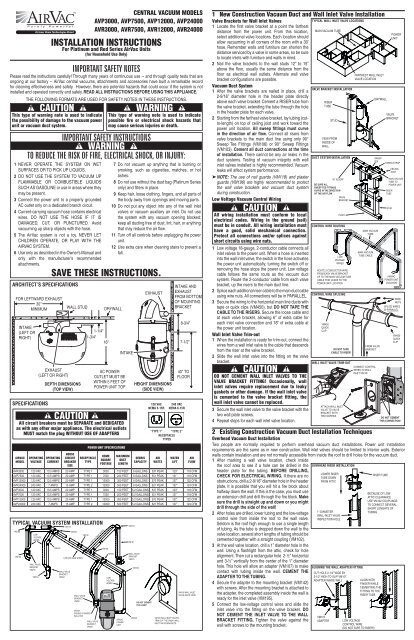
SPECIFICATIONS<br />
CAUTION<br />
All circuit breakers must be SEPARATE and DEDICATED<br />
as with any other major appliance. The electrical outlets<br />
MUST match the plug WITHOUT USE OF ADAPTERS<br />
AIRVAC<br />
MODEL<br />
OPERATING<br />
VOLTAGE<br />
OPERATING<br />
CURRENT<br />
HOUSE<br />
CIRCUIT<br />
BREAKER<br />
SIZE<br />
POWER UNIT SPECIFICATIONS<br />
RECEPTACLE<br />
TYPE<br />
HOME<br />
SQUARE<br />
FOOTAGE<br />
7 Do not vacuum up anything that is burning or<br />
smoking, such as cigarettes, matches, or hot<br />
ashes.<br />
8 Do not use without the dust bag (Platinum Series<br />
only) and filters in place.<br />
9 Keep hair, loose clothing, fingers, and all parts of<br />
the body away from openings and moving parts.<br />
10 Do not put any object into any of the wall inlet<br />
valves or vacuum auxiliary air inlet. Do not use<br />
the system with any vacuum opening blocked;<br />
keep all ducting free of dust, lint, hair, or anything<br />
that may reduce the air flow.<br />
11 Turn off all controls before unplugging the power<br />
unit.<br />
12 Use extra care when cleaning stairs to prevent a<br />
fall.<br />
MAXIMUM<br />
DUCT<br />
LENGTH<br />
VM103<br />
VM101<br />
WALL VALVE<br />
BRACKET<br />
VM241<br />
VM103<br />
VM103<br />
HEIGHT DIMENSIONS<br />
(SIDE VIEW)<br />
DEBRIS<br />
CAPACITY<br />
DO NOT CEMENT<br />
THIS JOINT!<br />
EXHAUST<br />
120 VAC<br />
NEMA 5-15R<br />
AIR<br />
WATTS<br />
VM195 WALL INLET VALVES<br />
TRIM OUT THE VM241 WALL<br />
INLET VALVE BRACKETS<br />
INTAKE AND<br />
EXHAUST<br />
FROM BOTTOM<br />
OF MOUNTING<br />
BRACKET<br />
8-3/4"<br />
7-1/2"<br />
40" TO<br />
FLOOR<br />
240 VAC<br />
NEMA 6-15R<br />
“TYPE 1” “TYPE 2”<br />
RECEPTACLE<br />
TYPES<br />
AVR3000 120 VAC 13.5 AMPS 20 AMP TYPE 1 3000 150 FEET 6 GALLONS 537 PEAK 123” 118 CFM<br />
AVR7500 120 VAC 13.5 AMPS 20 AMP TYPE 1 7500 200 FEET 6 GALLONS 551 PEAK 131” 118 CFM<br />
AVR12000 120 VAC 13.5 AMPS 20 AMP TYPE 1 12000 350 FEET 6 GALLONS 570 PEAK 127” 122 CFM<br />
AVR24000 240 VAC 7 AMPS 15 AMP TYPE 2 12000 500 FEET 6 GALLONS 627 PEAK 137” 124 CFM<br />
AVP3000 120 VAC 13.5 AMPS 20 AMP TYPE 1 3000 150 FEET 5.2 GALLONS 537 PEAK 123” 118 CFM<br />
AVP7500 120 VAC 13.5 AMPS 20 AMP TYPE 1 7500 200 FEET 5.2 GALLONS 551 PEAK 131” 118 CFM<br />
AVP12000 120 VAC 13.5 AMPS 20 AMP TYPE 1 12000 350 FEET 5.2 GALLONS 570 PEAK 127” 122 CFM<br />
AVP24000 240 VAC 7 AMPS 15 AMP TYPE 2 12000 500 FEET 5.2 GALLONS 627 PEAK 137” 124 CFM<br />
WATER<br />
LIFT<br />
AIR<br />
FLOW<br />
VM195 WALL INLET<br />
VALVE (BACK VIEW)<br />
1 New Construction <strong>Vacuum</strong> Duct and Wall Inlet Valve <strong>Installation</strong><br />
Valve Brackets for Wall Inlet Valves<br />
1 Locate the first valve bracket at a point the farthest<br />
distance from the power unit. From this location,<br />
select additional valve locations. Each location should<br />
allow vacuuming in all corners of the room with a 30’<br />
hose. Remember walls and furniture can shorten the<br />
distance serviced by a valve in some areas, so be sure<br />
to locate inlets with furniture and walls in mind.<br />
2 Nail the valve brackets to the wall studs 12” to 15”<br />
above the floor, usually the same distance from the<br />
floor as electrical wall outlets. Alternate wall valve<br />
bracket configurations are possible.<br />
<strong>Vacuum</strong> Duct <strong>System</strong><br />
1 After the valve brackets are nailed in place, drill a<br />
2-9/16” diameter hole in the header plate directly<br />
above each valve bracket. Cement a RISER tube from<br />
the valve bracket, extending the tube through the hole<br />
in the header plate for each valve.<br />
2 Starting from the farthest valve bracket, lay tubing (cutto-length)<br />
on top of ceiling joist and work toward the<br />
power unit location. All sweep fittings must curve<br />
in the direction of air flow. Connect all risers from<br />
valve brackets to the main duct line using only 90°<br />
Sweep Tee Fittings (VM106) or 90° Sweep Fittings<br />
(VM103). Cement all duct connections at the time<br />
of installation. There cannot be any air leaks in the<br />
duct systems. Testing of vacuum integrity with wall<br />
inlet valves installed is highly recommended. <strong>Vacuum</strong><br />
leaks will affect system performance.<br />
➤ NOTE: The use of nail guards (VM118) and plaster<br />
guards (VM196) are highly recommended to protect<br />
the wall valve brackets and vacuum duct system<br />
during construction.<br />
Low Voltage <strong>Vacuum</strong> Control Wiring<br />
CAUTION<br />
All wiring installation must conform to local<br />
electrical codes. Wiring in the ground (soil)<br />
must be in conduit. All wiring installation must<br />
have a good, solid mechanical connection.<br />
Protect all connections and/or splices against<br />
short circuits using wire nuts.<br />
1 Low voltage 18-gauge, 2-conductor cable connects all<br />
inlet valves to the power unit. When a hose is inserted<br />
into the wall inlet valve, the switch in the hose activates<br />
the power unit automatically; turning the switch off or<br />
removing the hose stops the power unit. Low voltage<br />
cable follows the same route as the vacuum duct<br />
system. Route the 2-conductor cable from each valve<br />
bracket, up the risers to the main duct line.<br />
2 Splice each additional riser cable to the main duct cable<br />
using wire nuts. All connections will be in PARALLEL.<br />
3 Secure the wiring to the horizontal main line ducts with<br />
tape or quick clips (VM450), but DO NOT TAPE THE<br />
CABLE TO THE RISERS. Secure the loose cable end<br />
at each valve bracket, allowing 6” of extra cable for<br />
each inlet valve connection and 18” of extra cable at<br />
the power unit location.<br />
Wall Inlet Valve Trim-out<br />
1 When the installation is ready for trim-out, connect the<br />
wires from a wall inlet valve to the cable that descends<br />
from the riser at the valve bracket.<br />
2 Slide the wall inlet valve into the fitting on the valve<br />
bracket.<br />
CAUTION<br />
DO NOT CEMENT WALL INLET VALVES TO THE<br />
VALVE BRACKET FITTING! Occasionally, wall<br />
inlet valves require replacement due to leaky<br />
gaskets or other damage. If the wall inlet valve<br />
is cemented to the valve bracket fitting, the<br />
wall inlet valve cannot be replaced.<br />
3 Secure the wall inlet valve to the valve bracket with the<br />
two wall plate screws.<br />
4 Repeat steps for each wall inlet valve location.<br />
2 Existing Construction <strong>Vacuum</strong> Duct <strong>Installation</strong> Techniques<br />
Overhead <strong>Vacuum</strong> Duct <strong>Installation</strong><br />
Two people are normally required to perform overhead vacuum duct installations. Power unit installation<br />
requirements are the same as in new construction. Wall inlet valves should be limited to interior walls. Exterior<br />
walls contain insulation and are not normally accessible from inside the roof to drill holes for the vacuum duct.<br />
1 After marking a wall valve location, check inside<br />
the roof area to see if a hole can be drilled in the<br />
header plate for the tubing. BEFORE DRILLING,<br />
CHECK FOR ELECTRICAL WIRING. If there are no<br />
obstructions, drill a 2-9/16” diameter hole in the header<br />
plate. It is possible that you will hit a fire block about<br />
halfway down the wall. If this is the case, you must use<br />
an extension drill and drill through the fire block. Make<br />
sure the drill is straight up and down or you might<br />
drill through the side of the wall!<br />
2 After holes are drilled, lower tubing and the low-voltage<br />
control wire from inside the roof to the wall valve.<br />
Seldom is the roof high enough to use a single length<br />
of tubing. As the tube is dropped down the wall to the<br />
valve location, several short lengths of tubing should be<br />
cemented together with a straight coupling (VM102).<br />
3 At the wall valve location, drill a 1” diameter hole in the<br />
wall. Using a flashlight from the attic, check for hole<br />
alignment. Then cut a rectangular hole 2-½” horizontal<br />
and 3-½” vertically from the center of the 1” diameter<br />
hole. This hole will allow an adapter (VM107) to make<br />
contact with tubing inside the wall. CEMENT THE<br />
ADAPTER TO THE TUBING.<br />
4 Secure the adapter to the mounting bracket (VM142)<br />
with screws. After the mounting bracket is attached to<br />
the adapter, the completed assembly inside the wall is<br />
ready for the inlet valve (VM195).<br />
5 Connect the low-voltage control wires and slide the<br />
inlet valve into the fitting on the valve bracket. DO<br />
NOT CEMENT THE INLET VALVE TO THE WALL<br />
BRACKET FITTING. Tighten the valve against the<br />
wall with screws to the mounting bracket.<br />
TYPICAL WALL INLET VALVE LOCATIONS<br />
MAIN VACUUM TUBE<br />
VALVE BRACKET INSTALLATION<br />
RISER<br />
TUBE<br />
STUD<br />
VIEW FROM<br />
INSIDE OF<br />
WALL<br />
DUCT SYSTEM INSTALLATION<br />
90˚ ELBOW<br />
BE SURE ALL<br />
SWEEP TEE FITTINGS<br />
CURVE IN THE DIRECTION<br />
OF THE AIR FLOW<br />
VALVE<br />
BRACKET<br />
PLATE<br />
CONTROL WIRE ROUTING<br />
LOW<br />
VOLTAGE<br />
WIRES<br />
ROUTE 2-CONDUCTOR WIRE<br />
FROM EACH VALVE BRACKET<br />
UP TO THE MAIN VACUUM TUBE<br />
CABLE THAT LEADS TO THE<br />
POWER UNIT LOCATION<br />
CONTROL WIRE SPLICING<br />
VM450<br />
QUICK<br />
CLIP<br />
DO NOT TAPE<br />
CABLE TO RISER!<br />
WALL INLET VALVE TRIM-OUT<br />
ATTACH WALL INLET<br />
VALVE TO VALVE<br />
BRACKET WITH<br />
TWO SCREWS<br />
OVERHEAD RISER INSTALLATION<br />
LOWER RISER<br />
TUBE DOWN<br />
FROM ATTIC<br />
1“ DIAMETER<br />
WALL INLET VALVE<br />
INSPECTION HOLE<br />
ALIGNING THE WALL ADAPTER FITTING<br />
CUT HOLE 2-1/2” WIDE BY<br />
3-1/2” HIGH TO SLIP VM107<br />
ADAPTER INSIDE WALL<br />
VM107<br />
ADAPTER<br />
FARTHEST WALL INLET<br />
VALVE LOCATION<br />
MAIN VACUUM<br />
TUBE CABLE<br />
DRYWALL<br />
SWEEP<br />
TEE<br />
MAIN VACUUM<br />
TUBE<br />
FROM VALVE<br />
BRACKET<br />
CONNECT CONTROL<br />
WIRES TO WALL<br />
INLET VALVE<br />
LOW VOLTAGE<br />
CONTROL WIRE<br />
(DO NOT TAPE TO RISER!)<br />
POWER<br />
UNIT<br />
VALVE<br />
BRACKET<br />
TUBING STRAP<br />
RISER<br />
TUBE<br />
CEILING<br />
JOIST<br />
MAIN VACUUM<br />
TUBE TO<br />
POWER UNIT<br />
STUD<br />
AIRVAC<br />
POWER UNIT<br />
LOCATION<br />
WIRE<br />
NUTS<br />
SPLICE WIRES<br />
IN PARALLEL<br />
VM450<br />
QUICK<br />
CLIP<br />
DO NOT CEMENT<br />
THIS CONNECTION!<br />
RISER TUBE<br />
BECAUSE OF LOW<br />
ATTIC CLEARANCE<br />
USE VM102 COUPLINGS<br />
TO CONNECT SEVERAL<br />
SHORT LENGHTS OF<br />
TUBING<br />
ALIGN WITH<br />
FINGER WHILE<br />
CEMENTING THE<br />
FITTING TO THE<br />
RISER TUBE
Overhead <strong>Vacuum</strong> Duct <strong>Installation</strong> (continued)<br />
6 Secure the inlet valve to the valve bracket with the two<br />
wall plate screws.<br />
7 Repeat steps for each wall inlet valve location.<br />
Under the Floor <strong>Installation</strong><br />
In homes with a pier and beam foundation or basement,<br />
either the overhead or an under the floor installation can<br />
be made. Sometimes under the floor installation is easier<br />
in an existing home, especially if the roof has a low pitch<br />
and clearances in the attic adds to the installation problem.<br />
Under the floor installation also eliminates encountering<br />
fire blocks in the wall. Shorter risers are also utilized,<br />
eliminating the longer tube drop from the attic.<br />
1 <strong>Vacuum</strong> tubing should be secured to floor joist with<br />
perforated nailing strips or tube straps.<br />
2 Generally, follow the overhead installation steps, but<br />
from below the floor, to install each wall inlet valve.<br />
Alternate <strong>Vacuum</strong> Duct Riser <strong>Installation</strong><br />
An effective technique highly suitable for many types<br />
of construction with adequate working room inside the<br />
attic is to make drops to the wall inlet valves through the<br />
ceiling, then route the tube through the wall at inlet level<br />
for the inlet valve on the opposite side of the wall. If this<br />
method is used, the drop from the inside of the attic for the<br />
riser can be made in the corner of a closet, utility room,<br />
etc. where the tubing is not visible or not objectionable<br />
to the Homeowner. On occasion this might be the only<br />
alternative for placing an inlet valve in a desired location.<br />
3 Power Unit <strong>Installation</strong><br />
Power Unit Unpacking and Pre-assembly<br />
This <strong>AirVac</strong> power unit is packaged disassembled in a nested configuration which reduces the size of the shipping<br />
carton and allows for much smaller shelf space requirements than previous <strong>AirVac</strong> models. The power unit must<br />
be assembled during installation.<br />
1 Carefully remove the nested vacuum from the box.<br />
2 Separate each of the nested parts and place them<br />
gently on the floor.<br />
3 Refer to the parts identification figure below to<br />
familiarize yourself with each of the parts.<br />
VACUUM PARTS IDENTIFICATION<br />
VACUUM BODY<br />
EXHAUST MUFFLER<br />
EXHAUST ELBOW<br />
INLET PLUG<br />
MOUNTING<br />
BRACKET<br />
FLEXIBLE HOSE<br />
LAG<br />
SCREWS<br />
HOSE<br />
CLAMPS<br />
CAUTION<br />
Do not mount the motor head onto the vacuum<br />
body until AFTER the vacuum body is hung on<br />
the mounting bracket. Placing the motor head<br />
on the vacuum body before mounting causes<br />
the unit to be top heavy and may tip the vacuum<br />
over, causing damage to the vacuum.<br />
4 Connect the 90° steel exhaust elbow to the motor<br />
head. The exhaust elbow can point to the left or right<br />
depending on the installation requirements. Secure<br />
the exhaust elbow to the motor head flange with the<br />
#4 self-tapping screw.<br />
5 PLATINUM SERIES ONLY: Install the dust cone inside<br />
the bottom end of the vacuum body as shown in the<br />
figure. Be sure the cone snaps against the large ridge in<br />
the vacuum body. DO NOT PUSH DUST CONE PAST<br />
THE LARGE RIDGE!<br />
6 PLATINUM SERIES ONLY: Install the slide-gate collar<br />
dust bag into the debris bucket. BE SURE TO FULLY<br />
EXPAND THE BAG WITH YOUR HAND TO FILL THE<br />
BUCKET.<br />
Power Unit Mounting<br />
1 Determine the mounting location for the power unit. Be<br />
sure clearance dimensions are followed. The power<br />
supply cord length is 5 feet. An AC power outlet of the<br />
proper type on a dedicated circuit breaker must be<br />
available within 5 feet so the power supply cord can be<br />
directly plugged into the electrical outlet. DO NOT USE<br />
AN EXTENSION CORD.<br />
2 Use a stud finder to locate a wall stud for attaching the<br />
mounting bracket. Mark the stud location.<br />
3 Attach the mounting bracket to the wall, centered on the<br />
marked stud, with the bottom edge 40" above the floor,<br />
using the two 1/4" x 2" lag screws and a 7/16" socket.<br />
4 Carefully hang the vacuum body by sliding the body’s<br />
mounting tab into the mounting bracket slot.<br />
5 Fit the motor head onto the vacuum body with the<br />
controls facing forward latching the two locking snaps.<br />
6 Hang the debris bucket on the two bucket slide latches.<br />
Swing the two slide latch handles up to lock the debris<br />
bucket into place.<br />
7 Slide the exhaust muffler onto the exhaust elbow.<br />
Optional Exhaust Tubing<br />
The vacuum’s exhaust can be piped away from the<br />
power unit if desired or required. The exhaust tubing<br />
must vent to the outside of the house, NOT INTO THE<br />
ATTIC. A louvered exhaust vent cap (VM136) is available<br />
to terminate the exhaust tubing. Steel tubing is also<br />
available for the exhaust tubing and may be required by<br />
local building codes.<br />
CAUTION<br />
In order to avoid motor failure resulting from<br />
excessive back pressure, DO NOT install more<br />
than 30 feet of exhaust tubing and DO NOT<br />
install any bends in the exhaust tubing closer<br />
than 18" from the exhaust muffler.<br />
1 Install any optional exhaust tubing following the<br />
guidance above.<br />
2 Connect the optional exhaust tubing to the muffler.<br />
UNDER FLOOR INSTALLATION<br />
INSTALL<br />
VALVE BRACKET<br />
12" TO 15" ABOVE<br />
FLOOR LEVEL<br />
ALTERNATE DUCT RISER INSTALLATION<br />
THE TUBING DROP<br />
CAN BE INSIDE A CLOSET<br />
THEN THROUGH THE<br />
WALL TO THE WALL<br />
VALVE INSIDE THE ROOM<br />
SLIDE-GATE COLLAR BAG<br />
(PLATINUM SERIES ONLY)<br />
DUST CONE<br />
(PLATINUM SERIES ONLY)<br />
DEBRIS BUCKET<br />
ATTACH MOUNTING BRACKET<br />
TO WALL WITH TWO LAG SCREWS<br />
SCREW TO<br />
WALL STUD<br />
SNAP MOTOR HEAD<br />
ONTO VACUUM BODY<br />
FLOOR<br />
BOTTOM<br />
EDGE 40"<br />
ABOVE<br />
FLOOR<br />
RETAINING<br />
SNAP<br />
PLATE<br />
TO WALL VALVE<br />
ON OTHER SIDE<br />
OF THE WALL<br />
DUST BAG INSTALLATION (PLATINUM SERIES ONLY)<br />
EXPAND THE DUST<br />
BAG BEFORE PLACING<br />
IT INTO THE DEBRIS BUCKET<br />
INSTALLING THE MOTOR HEAD AND DEBRIS BUCKET<br />
HANG DEBRIS<br />
BUCKET ON BUCKET<br />
SLIDE LATCHES<br />
BUCKET<br />
SLIDE<br />
LATCH<br />
HOLE IN<br />
CEILING<br />
RISER AND<br />
CONTROL<br />
WIRE<br />
MOTOR HEAD<br />
HANGING THE MOUNTING BRACKET & MOUNTING THE VACUUM BODY<br />
OPTIONAL EXHAUST TUBING<br />
VM106<br />
SWEEP TEE<br />
FLOOR<br />
JOIST<br />
EXHAUST ELBOW & DUST CONE INSTALLATION<br />
ATTACH THE EXHAUST<br />
ELBOW TO THE MOTOR<br />
HEAD WITH #4 SCREW<br />
EXHAUST ELBOW<br />
CAN POINT TO<br />
LEFT OR RIGHT<br />
DO NOT PRESS<br />
CONE PAST THE<br />
LARGE RIDGE<br />
PLACE BAG'S<br />
SLIDE-GATE<br />
HERE<br />
SLIDE-GATE COLLAR BAG<br />
18" MINIMUM FROM<br />
THE MUFFLER BEFORE<br />
ANY BENDS IN THE<br />
EXHAUST TUBING<br />
EXHAUST TUBING<br />
MUST VENT OUTSIDE<br />
OF THE HOUSE<br />
VM136<br />
LOUVERED<br />
EXHAUST<br />
VENT CAP<br />
FLOW<br />
MAIN VACUUM TUBE<br />
PLACE THE BAG INTO THE<br />
DEBRIS BUCKET AND<br />
EXPAND THE BAG AGAINST<br />
THE DEBRIS BUCKET SIDES<br />
HANG VACUUM BODY ON<br />
MOUNTING BRACKET<br />
SWING THE TWO<br />
BUCKET SLIDE<br />
LATCHES UP<br />
OUTSIDE<br />
WALL<br />
STUD<br />
TIP DUST CONE<br />
INTO VACUUM BODY<br />
BOTTOM END<br />
PRESS DUST CONE<br />
IN UNTIL THE FOUR<br />
TABS SNAP AGAINST<br />
THE LARGE RIDGE<br />
<strong>Vacuum</strong> Intake Connection<br />
Depending on the requirements of the installation, the<br />
main vacuum duct line can be connected to the left or<br />
right side intake port of the power unit.<br />
1 Cut a 4" piece of duct tubing.<br />
2 Slide the tubing piece into the left or right power unit<br />
intake port. DO NOT CEMENT TUBING.<br />
3 Slide a hose clamp onto the flexible hose. Slide the<br />
flexible hose onto the tubing piece. Tighten the hose<br />
clamp.<br />
4 Slide another hose clamp onto the flexible hose.<br />
Connect the flexible hose to the drop from the main<br />
vacuum duct system line. Tighten the hose clamp.<br />
5 The unused power unit intake port MUST be sealed,<br />
slide the inlet plug onto the unused intake port.<br />
4 Power Unit Electrical<br />
Low Voltage Control Wire Connection<br />
1 Strip back the insulation about 1/2" from the twoconductor<br />
low voltage control wire cable at the power<br />
unit.<br />
2 Using a small screwdriver or other object, press down<br />
on one of the wire locks on the control wire connector<br />
(top rear of motor head) while inserting the wire<br />
into the connector hole. Release the wire lock while<br />
holding the wire in. Repeat with the other wire and the<br />
other hole. Polarity is not important, either wire can be<br />
connected to either hole.<br />
Grounding <strong>Instructions</strong><br />
This appliance must be grounded. If it should malfunction or breakdown, grounding provides a path of least<br />
resistance for electrical current to reduce the risk of electrical shock. This appliance is equipped with a cord having<br />
an equipment-grounding conductor and grounding plug. The plug must be plugged into an appropriate outlet that<br />
is properly installed and grounded in accordance with all local codes and ordinances.<br />
WARNING<br />
Improper connection of the equipment-grounding<br />
conductor can result in risk of electric shock.<br />
Check with a qualified electrician or service<br />
person if you are in doubt as to whether the<br />
outlet is properly grounded. Do not modify the<br />
plug provided with the appliance - if it will not<br />
fit the outlet, have a proper outlet installed by a<br />
qualified electrician.<br />
Power Connection<br />
1 BE SURE THE UNIT’S POWER SWITCH IS OFF.<br />
Plug the line cord into the AC receptacle.<br />
2 Verify that power is available to the vacuum by<br />
switching the unit’s power on then off.<br />
<strong>System</strong> Testing<br />
The <strong>AirVac</strong> central vacuum system should be tested for good suction throughout the system. Use a vacuum gauge<br />
(VM181) at each wall inlet valve location to measure the vacuum suction.<br />
5 Troubleshooting<br />
NOTE: NO USER SERVICEABLE PARTS INSIDE, DO NOT LUBRICATE MOTOR.<br />
IF THE MOTOR FAILS TO OPERATE<br />
1 Be sure the power unit is plugged into a working AC outlet.<br />
2 Push breaker reset button on the power unit.<br />
3 Check the panel circuit breaker that connects the power unit.<br />
AFTER CHANGING OF THE BAG (PLATINUM SERIES ONLY)<br />
1 Push down the RESET button for 7 seconds to reset the bag indicator.<br />
IN CASE OF LOW VACUUM POWER<br />
1 Be sure that the inlet plug is inserted into the unused power unit intake port.<br />
2 Check that all wall valves are closed.<br />
3 Check that all gaskets on wall valves are sealed.<br />
4 Check to see if debris bucket or bag (Platinum Series only) needs emptying.<br />
5 Check for obstructions in the hose, tools, or vacuum lines.<br />
6 Check for any ruptures or breaks in the vacuum duct system.<br />
If you are unable to resolve the operational problems, please contact <strong>AirVac</strong> technical support at (800) 421-1587.<br />
6 Limited Warranty<br />
Linear LLC warrants <strong>AirVac</strong> Platinum Series power units to be free of defects for<br />
10 years, and <strong>AirVac</strong> Red Series power units to be free of defects for 5 years.<br />
The warranty period begins from either (1) the date of “first user” purchase of<br />
this product or (2) the first close of escrow date on a residence in which this<br />
new product was originally installed. This warranty extends to the original user<br />
of the product and to each subsequent owner of the product during the term of<br />
this warranty. Linear LLC will repair or replace, at its option, parts and materials<br />
at no charge. Parts supplied under this warranty may be new or rebuilt at the<br />
option of Linear LLC.<br />
If, during the limited warranty period, it appears as though this product contains<br />
a defect which is covered by this limited warranty, call our toll free service<br />
number before dismantling the product (1-800-421-1587). Remember to<br />
attain a Return Product Authorization number (RPA) before returning any<br />
product to Linear LLC. Send this product freight pre-paid and insured<br />
to our service center for warranty repair. You will be advised on shipping<br />
instructions when you call the toll free service number. Linear LLC will return<br />
the repaired product freight pre-paid within the U.S.A. The installing dealer or<br />
distributor may assist you, at your choice and expense, with returning product<br />
for repair. Please include a brief description of the problem and a dated proofof-purchase<br />
receipt with any product that is returned for warranty repair. ANY<br />
PRODUCT RETURNED WITHOUT A RETURN PRODUCT AUTHORIZATION<br />
NUMBER WILL BE REFUSED.<br />
Copyright © 2006 Linear LLC<br />
VACUUM INTAKE CONNECTION<br />
LOW VOLTAGE<br />
CONTROL WIRE<br />
CONNECTOR<br />
(760) 438-7000<br />
USA & Canada (800) 421-1587 & (800) 392-0123<br />
Toll Free FAX (800) 468-1340<br />
www.linearcorp.com<br />
VACUUM<br />
INTAKE PORT<br />
HOSE<br />
CLAMPS<br />
FLEXIBLE<br />
HOSE<br />
LOW VOLTAGE CONTROL WIRE CONNECTION<br />
THE UNUSED<br />
INTAKE PORT<br />
MUST BE SEALED!<br />
MAIN<br />
VACUUM<br />
TUBE<br />
INSERT THE INLET<br />
PLUG ONTO THE<br />
UNUSED VACUUM<br />
INTAKE PORT<br />
LOW VOLTAGE<br />
CONTROL WIRE<br />
FROM WALL VALVES<br />
PUSH EACH WIRE<br />
LOCK DOWN WHILE<br />
INSERTING THE WIRE<br />
INTO THE CONECTOR<br />
HOLE<br />
CAUTION<br />
All circuit breakers must be SEPARATE and<br />
DEDICATED as with any other major appliance.<br />
The electrical outlets MUST match the plug<br />
WITHOUT THE USE OF ADAPTERS. DO NOT USE<br />
AN EXTENSION CORD.<br />
AC POWER CONNECTION<br />
BE SURE THE POWER<br />
SWITCH IS OFF<br />
www.purelypowerful.com<br />
Manufactured by:<br />
PLUG THE POWER UNIT<br />
INTO A GROUNDED<br />
AC OUTLET THAT IS<br />
WIRED TO A DEDICATED<br />
CIRCUIT BREAKER<br />
DO NOT USE AN<br />
EXTENSION CORD<br />
OR AN AC ADAPTER!<br />
THIS LIMITED WARRANTY IS IN LIEU OF ANY OTHER WARRANTIES,<br />
EXPRESS OR IMPLIED, INCLUDING ANY IMPLIED WARRANTY OF<br />
MERCHANTABILITY OR FITNESS FOR A PARTICULAR PURPOSE OR<br />
OTHERWISE, AND OF ANY OTHER OBLIGATIONS OR LIABILITY ON THE<br />
SELLER’S PART. THIS LIMITED WARRANTY DOES NOT COVER DAMAGE<br />
CAUSED BY ACTS OF GOD, IMPROPER INSTALLATION, NORMAL<br />
SYSTEM WEAR AND TEAR AS DEFINED BY THE MANUFACTURER, THE<br />
VIOLATION OF APPLICABLE BUILDING OR ELECTRICAL CODES, OR<br />
THE USE OF NON-AIRVAC WIRE, CABLE, OR WALL HOUSINGS. THIS<br />
LIMITED WARRANTY APPLIES ONLY TO PRODUCTS INSTALLED IN A<br />
PRIVATE RESIDENCE.<br />
UNDER NO CIRCUMSTANCES SHALL THE SELLER BE LIABLE FOR<br />
CONSEQUENTIAL, INCIDENTAL OR SPECIAL DAMAGES ARISING IN<br />
CONNECTION WITH USE, OR INABILITY TO USE THIS PRODUCT. IN<br />
NO EVENT SHALL SELLER’S LIABILITY, FOR BREACH OF WARRANTY,<br />
BREACH OF CONTRACT, NEGLIGENCE, OR STRICT LIABILITY, EXCEED<br />
THE COST OF THE PRODUCT COVERED HEREBY. NO PERSON<br />
IS AUTHORIZED TO ASSUME FOR US ANY OTHER LIABILITY IN<br />
CONNECTION WITH THE SALE OF THIS PRODUCT.<br />
Some states do not allow the exclusion or limitation of consequential, incidental<br />
or special damages, so the above limitation or exclusion may not apply to you.<br />
This limited warranty gives you specific legal rights, and you may also have<br />
other rights which vary from state to state.<br />
226529 A
