Tensile and fatigue properties of fiber laser welded high strength low ...
Tensile and fatigue properties of fiber laser welded high strength low ...
Tensile and fatigue properties of fiber laser welded high strength low ...

You also want an ePaper? Increase the reach of your titles
YUMPU automatically turns print PDFs into web optimized ePapers that Google loves.
Materials <strong>and</strong> Design 43 (2013) 373–383<br />
Contents lists available at SciVerse ScienceDirect<br />
Materials <strong>and</strong> Design<br />
journal homepage: www.elsevier.com/locate/matdes<br />
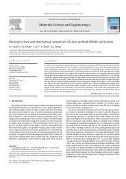
<strong>Tensile</strong> <strong>and</strong> <strong>fatigue</strong> <strong>properties</strong> <strong>of</strong> <strong>fiber</strong> <strong>laser</strong> <strong>welded</strong> <strong>high</strong> <strong>strength</strong> <strong>low</strong> alloy<br />
<strong>and</strong> DP980 dual-phase steel joints<br />
W. Xu a , D. Westerbaan b , S.S. Nayak b , D.L. Chen a,⇑ , F. Goodwin c , Y. Zhou b<br />
a Department <strong>of</strong> Mechanical <strong>and</strong> Industrial Engineering, Ryerson University, 350 Victoria Street, Toronto, Ontario M5B 2K3, Canada<br />
b Department <strong>of</strong> Mechanical <strong>and</strong> Mechatronics Engineering, University <strong>of</strong> Waterloo, 200 University Avenue West, Waterloo, Ontario N2L 3G1, Canada<br />
c International Zinc Association, Durham, NC 27713, USA<br />
article<br />
info<br />
abstract<br />
Article history:<br />
Received 2 June 2012<br />
Accepted 8 July 2012<br />
Available online 16 July 2012<br />
Keywords:<br />
Fiber <strong>laser</strong> welding<br />
High <strong>strength</strong> <strong>low</strong> alloy steel<br />
Dual-phase steel<br />
Microstructure<br />
Fatigue<br />
The study was aimed at evaluating the microstructure <strong>and</strong> mechanical <strong>properties</strong> <strong>of</strong> <strong>high</strong>-speed <strong>fiber</strong><br />
<strong>laser</strong> <strong>welded</strong> <strong>high</strong> <strong>strength</strong> <strong>low</strong> alloy (HSLA) <strong>and</strong> DP980 dual-phase steel joints with varying weld geometries.<br />
Fusion zone (FZ) consisted <strong>of</strong> martensitic structure, <strong>and</strong> heat-affected zone (HAZ) contained<br />
newly-formed martensite in both steels <strong>and</strong> partially tempered martensite in DP980. While HAZ-s<strong>of</strong>tening<br />
was present in DP980, it was absent in HSLA. A distinctive ‘‘suspension bridge’’-like hardness pr<strong>of</strong>ile<br />
with the FZ hardness as a ‘‘pylon’’ appeared in the <strong>fiber</strong> <strong>laser</strong> <strong>welded</strong> joints. Both HSLA <strong>and</strong> DP980 joints<br />
showed a superior tensile <strong>strength</strong>, with a joint efficiency <strong>of</strong> 94–96% <strong>and</strong> 96–97%, respectively, despite a<br />
reduced elongation in DP980 joints. Fatigue <strong>strength</strong> was <strong>high</strong>er in DP980 joints than in HSLA joints at<br />
<strong>high</strong>er stress amplitudes, but had no obvious difference at <strong>low</strong>er stress amplitudes. DP980 multiple linear<br />
welds exhibited a larger scatter <strong>and</strong> <strong>low</strong>er <strong>fatigue</strong> <strong>strength</strong>. Fatigue failure <strong>of</strong> HSLA joints occurred in the<br />
base metal at a stress amplitude above 250 MPa, <strong>and</strong> at weld concavity at a <strong>low</strong>er stress amplitude be<strong>low</strong><br />
250 MPa. Fatigue crack in DP980 joints initiated predominantly from the weld concavity at both <strong>high</strong> <strong>and</strong><br />
<strong>low</strong> levels <strong>of</strong> stress amplitudes.<br />
Ó 2012 Elsevier Ltd. All rights reserved.<br />
1. Introduction<br />
The dem<strong>and</strong> <strong>of</strong> environment-friendly vehicles that have better<br />
fuel economy <strong>and</strong> <strong>low</strong>er CO 2 emissions compels automakers to<br />
apply advanced technology <strong>and</strong> new materials in vehicle manufacturing<br />
[1–4]. During manufacturing <strong>of</strong> automotive components,<br />
welding <strong>and</strong> joining are unavoidable. Laser welding is an enabling<br />
technology which is fast <strong>and</strong> precise in joining a wide variety <strong>of</strong><br />
materials with varying thicknesses <strong>and</strong> types [5,6]. A new generation<br />
<strong>of</strong> <strong>fiber</strong> <strong>laser</strong>s has been developed for industrial applications<br />
<strong>and</strong> has multiple advantages, including <strong>high</strong> power with small<br />
beam divergence, flexible beam delivery, <strong>low</strong> maintenance costs,<br />
<strong>high</strong> efficiency, <strong>and</strong> compact size [7,8].<br />
A lot <strong>of</strong> studies on <strong>laser</strong> welding <strong>of</strong> HSLA, DP980, <strong>and</strong> other<br />
steels have been reported in the literature [9–12]. For example,<br />
Saunders <strong>and</strong> Wagone [9] conducted a study on Nd:YAG <strong>and</strong> CO 2<br />
<strong>laser</strong> welding <strong>of</strong> the aluminum-killed drawing quality (AKDQ) steel<br />
<strong>and</strong> HSLA steel sheets in which they concluded that the intrinsic<br />
ductility <strong>of</strong> AKDQ <strong>and</strong> HSLA steel reduced after <strong>laser</strong> welding. In<br />
another study, Sreenivasan et al. [10] investigated the mechanical<br />
<strong>properties</strong> <strong>and</strong> performance <strong>of</strong> DP980 steel tailor <strong>welded</strong> blanks<br />
manufactured using Nd:YAG <strong>and</strong> diode <strong>laser</strong> welding (DLW).<br />
⇑ Corresponding author. Tel.: +1 416 979 5000x6487; fax: +1 416 979 5265.<br />
E-mail address: dchen@ryerson.ca (D.L. Chen).<br />
Formability <strong>and</strong> uniaxial tensile <strong>strength</strong> <strong>of</strong> DP980 <strong>welded</strong> blanks<br />
significantly reduced due to the occurrence <strong>of</strong> heat affected zone<br />
(HAZ)-s<strong>of</strong>tening, i.e., the hardness at outer HAZ being significantly<br />
be<strong>low</strong> that <strong>of</strong> the base material caused by tempering <strong>of</strong> martensite.<br />
Similar effect <strong>of</strong> HAZ-s<strong>of</strong>tening on the formability was observed by<br />
Xia et al. [11] in their comparative study <strong>of</strong> HSLA <strong>and</strong> DP980 steel<br />
joints prepared using DLW. The study suggested a <strong>low</strong>er formability<br />
<strong>of</strong> DP980 diode <strong>laser</strong> <strong>welded</strong> blanks compared to the base metal<br />
(BM), which could be improved by increasing welding speed which<br />
in turn reduced the HAZ-s<strong>of</strong>tening. In addition, it was also reported<br />
that changes in the microstructure <strong>and</strong> hardness in the HAZ <strong>and</strong> FZ,<br />
in diode <strong>laser</strong> welds with similar <strong>and</strong> dissimilar combination <strong>of</strong><br />
DP600 <strong>and</strong> DP980 steel, resulted in a change <strong>of</strong> <strong>fatigue</strong> performance<br />
[13,14].<br />
The important outcome <strong>of</strong> the above mentioned studies was<br />
that microstructural heterogeneity (mainly HAZ-s<strong>of</strong>tening) significantly<br />
affects the mechanical <strong>properties</strong> such as tensile <strong>and</strong> <strong>fatigue</strong><br />
<strong>strength</strong> <strong>and</strong> also the formability <strong>of</strong> <strong>laser</strong> <strong>welded</strong> HSLA <strong>and</strong> DP980<br />
joints. High speed <strong>fiber</strong> <strong>laser</strong> welding (FLW) is becoming increasingly<br />
important <strong>and</strong> its share in the total <strong>laser</strong> industry is expected<br />
to grow substantially [8]. One <strong>of</strong> the reasons is that the <strong>high</strong> power<br />
density, small beam divergence <strong>and</strong> focal spot diameter could lead<br />
to welds with a <strong>high</strong>er penetration <strong>and</strong> smaller width for a given<br />
welding speed [7]. However, there is no report so far on the effect<br />
<strong>of</strong> FLW on the microstructure <strong>and</strong> mechanical <strong>properties</strong> <strong>of</strong> the<br />
0261-3069/$ - see front matter Ó 2012 Elsevier Ltd. All rights reserved.<br />
http://dx.doi.org/10.1016/j.matdes.2012.07.017
374 W. Xu et al. / Materials <strong>and</strong> Design 43 (2013) 373–383<br />
Table 1<br />
Compositions <strong>of</strong> the HSLA <strong>and</strong> DP980 steel used in the present study.<br />
Steel grade C Mn Si Al Mo Cr N<br />
HSLA 0.0795 0.827 0.454 0.048 0.007 0.033 0.007<br />
DP980 0.15 1.5 0.31 0.05 N/A N/A N/A<br />
important automotive steels namely HSLA <strong>and</strong> DP980. It is unclear<br />
how serious the HAZ s<strong>of</strong>tening in the HSLA <strong>and</strong> DP980 steels after<br />
FLW is, <strong>and</strong> if the multiple linear FLW would have a significant effect<br />
on the <strong>fatigue</strong> <strong>strength</strong>. This study was, therefore, aimed at<br />
identifying the evolution <strong>of</strong> microstructure <strong>and</strong> the effects <strong>of</strong><br />
FLW on the <strong>fatigue</strong> resistance in HSLA <strong>and</strong> DP980 steels. The effects<br />
<strong>of</strong> weld geometry, i.e., single <strong>and</strong> multiple linear welds, on the<br />
microstructure <strong>and</strong> <strong>fatigue</strong> <strong>properties</strong> <strong>of</strong> the <strong>welded</strong> joints have<br />
also been evaluated.<br />
2. Material <strong>and</strong> experimental procedure<br />
The starting materials in the present study were hot-dip galvanizing<br />
(GI) coated HSLA <strong>and</strong> DP980 steel with a thickness <strong>of</strong><br />
1.2 mm; the chemical compositions <strong>of</strong> the steels are given in Table<br />
1. Butt welding <strong>of</strong> the steel sheets was carried out using an<br />
IPG PhotonicsYLS-6000 <strong>fiber</strong> <strong>laser</strong> system with a power <strong>of</strong> 6 kW,<br />
a welding speed <strong>of</strong> 16 m/min, a focal length <strong>of</strong> 30 cm. The <strong>fiber</strong> <strong>laser</strong><br />
had a <strong>fiber</strong> core diameter <strong>of</strong> 0.3 mm with a <strong>laser</strong> beam spot<br />
size/diameter <strong>of</strong> 0.6 mm. The weld geometries <strong>and</strong> dimensions <strong>of</strong><br />
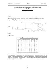
the steel sheets used in this study are shown in Fig. 1a. Welding<br />
was performed with 0° head angle, i.e., the <strong>laser</strong> beam was perpendicular<br />
to the surface <strong>of</strong> work pieces <strong>and</strong> without any shielding gas.<br />
The metallographic samples for the microstructural examination<br />
were cut from the weld cross-section, then mounted, ground,<br />
polished, <strong>and</strong> etched with a 2% Nital solution. The etched samples<br />
were observed using a light microscope along with a Clemex image<br />
analysis system <strong>and</strong> JEOL JSM-6380 scanning electron microscope<br />
(SEM), equipped with Oxford energy dispersive X-ray spectroscopy<br />
(EDS) <strong>and</strong> three-dimensional fractographic analysis capacity. Vickers<br />
microhardness was measured on the polished samples across<br />
the weld using a computerized microhardness tester at a load <strong>of</strong><br />
200 g <strong>and</strong> a dwell time <strong>of</strong> 15 s. All indentations were adequately<br />
spaced to prevent any potential effect <strong>of</strong> strain fields caused by<br />
adjacent indentations. To ensure the validity <strong>of</strong> test results, two<br />
calibration tests were done using a st<strong>and</strong>ard reference test block<br />
before the microhardness tests on the <strong>welded</strong> joints.<br />
<strong>Tensile</strong> <strong>and</strong> <strong>fatigue</strong> test samples fol<strong>low</strong>ing ASTM-E8/E8M st<strong>and</strong>ard<br />
[15] were sectioned from the <strong>welded</strong> blanks in the rolling<br />
direction (i.e., perpendicular to the welding direction), the examples<br />
<strong>of</strong> which are indicated by the dashed line in Fig. 1a with the<br />
geometry <strong>and</strong> dimensions <strong>of</strong> the test coupons shown in Fig. 1b<br />
<strong>and</strong> c. The test coupons were machined in such a way that the weld<br />
was positioned at the center <strong>of</strong> gauge length for the single linear<br />
weld (Fig. 1b), or two welds were located within the gauge length<br />
symmetrically with respect to the middle <strong>of</strong> the sample (Fig. 1c).<br />
To identify the effect <strong>of</strong> welding <strong>and</strong> its geometry on the tensile<br />
<strong>and</strong> <strong>fatigue</strong> <strong>properties</strong>, coupons <strong>of</strong> the BM were also prepared<br />
<strong>and</strong> tested. <strong>Tensile</strong> tests were conducted using a fully computerized<br />
United tensile testing machine at room temperature <strong>and</strong> with<br />
a range <strong>of</strong> strain rates from 1 10 5 to 1 10 2 s 1 . An extensometer<br />
with a gauge length <strong>of</strong> 50 mm <strong>and</strong> a strain limit <strong>of</strong> 20% was<br />
used to measure the strain during the tensile tests. Load control <strong>fatigue</strong><br />
tests were performed in accordance with ASTM E466 [16] on<br />
a fully computerized Instron 8801 servo-hydraulic testing system.<br />
To avoid potential buckling <strong>of</strong> the test specimens, tension–tension<br />
cyclic loading at a stress ratio <strong>of</strong> R = 0.1 was applied at a frequency<br />
Welding lines<br />
Welding lines<br />
HSLA<br />
HSLA<br />
HSLA<br />
HS HSLA<br />
DP<br />
DP<br />
DP DP DP<br />
Steel<br />
Steel<br />
Steel<br />
LA Steel<br />
Steel<br />
Steel<br />
Steel<br />
Steel<br />
Single linear weld Two linear welds Single linear weld Two linear welds<br />
(a)<br />
Rolling direction<br />
(b)<br />
(c)<br />
Name G W R L A B C<br />
Dimension (mm) 50 12.5 12.5 200 57 50 20<br />
(d)<br />
Fig. 1. Geometry <strong>and</strong> dimensions <strong>of</strong> work pieces <strong>and</strong> test specimens, (a) work pieces to be <strong>welded</strong> using a 6 kW <strong>fiber</strong> <strong>laser</strong>, (b) tensile <strong>and</strong> <strong>fatigue</strong> test samples sectioned from<br />
the single linear weld indicated by the short-dashed lines at (a), (c) tensile <strong>and</strong> <strong>fatigue</strong> test samples cut from the multiple linear weld indicated by the long-dashed lines at (a),<br />
<strong>and</strong> (d) a table <strong>of</strong> the specimen dimensions.
W. Xu et al. / Materials <strong>and</strong> Design 43 (2013) 373–383 375<br />
(a)<br />
(b)<br />
c<br />
e<br />
g<br />
d<br />
f<br />
h<br />
500 µm 500 µm<br />
(c)<br />
(d)<br />
150 µm 150 µm<br />
(e)<br />
(f)<br />
150 µm<br />
150 µm<br />
(g)<br />
(h)<br />
150 µm<br />
150 µm<br />
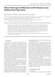
Fig. 2. Micrographs showing the microstructure change <strong>of</strong> a FLW HSLA <strong>and</strong> a FLW DP980 steel joint, (a) overall view <strong>of</strong> the cross section <strong>of</strong> the FLW HSLA steel joint, (b)<br />
overall view <strong>of</strong> the cross section <strong>of</strong> the FLW DP980 steel joint, (c) HSLA BM, (d) DP980 BM, (e) HAZ <strong>of</strong> the FLW HSLA steel joint, (f) HAZ <strong>of</strong> the FLW DP980 steel joint, (g) FZ <strong>of</strong><br />
the FLW HSLA steel joint <strong>and</strong> (h) FZ <strong>of</strong> the FLW DP980 steel joint.<br />
Table 2<br />
Comparison <strong>of</strong> the average width <strong>of</strong> HAZ <strong>and</strong> FZ in the <strong>welded</strong> joints made with different types <strong>of</strong> <strong>laser</strong> welding.<br />
Welding type<br />
Power<br />
(kW)<br />
Welding speed<br />
(m/min)<br />
Spot size<br />
(mm)<br />
Welding<br />
materials<br />
Thickness <strong>of</strong><br />
workpiece (mm)<br />
Average width <strong>of</strong><br />
HAZ (lm)<br />
Average width <strong>of</strong><br />
FZ (lm)<br />
DLW 4 1.6 12 ⁄ 0.5 DP980 steel 1.2 4000 3000 [11]<br />
Nd:YAG Laser 3 3 0.6 DP980 steel 1.17 1000 750 [10]<br />
welding<br />
CO 2 <strong>laser</strong> 6 6 – DP780 steel 1.8 1000 1000 [12]<br />
welding<br />
FLW 6 16 0.6 DP980 steel 1.2 250 450 Present<br />
study<br />
Reference
376 W. Xu et al. / Materials <strong>and</strong> Design 43 (2013) 373–383<br />
<strong>of</strong> 50 Hz <strong>and</strong> sinusoidal waveform. In both tensile <strong>and</strong> <strong>fatigue</strong> tests,<br />
at least two specimens were tested at each strain rate or each<br />
cyclic stress amplitude. The <strong>fatigue</strong> fracture surfaces were examined<br />
via a scanning electron microscope (SEM) to identify the initiation<br />
sites <strong>and</strong> propagation mechanism <strong>of</strong> the <strong>fatigue</strong> crack.<br />
3. Results <strong>and</strong> discussion<br />
3.1. Microstructure evolution<br />
The representative weld cross-section pr<strong>of</strong>iles <strong>and</strong> microstructure<br />
at different weld zones <strong>of</strong> the HSLA <strong>and</strong> DP980 joints made<br />
with the FLW are shown in Fig. 2. The cross-section <strong>of</strong> the welds<br />
showed a significant microstructural change in both HSLA <strong>and</strong><br />
DP980 joints, indicating the formation <strong>of</strong> the middle FZ <strong>and</strong> two<br />
adjacent HAZs which coexisted with the unaffected BM at both left<br />
<strong>and</strong> right ends as indicated in Fig. 2a <strong>and</strong> b. It is seen that the width<br />
<strong>of</strong> HAZ <strong>and</strong> FZ in both HSLA <strong>and</strong> DP980 joints was similar with an<br />
average <strong>of</strong> 200–300 lm, <strong>and</strong> 400–500 lm, respectively. The HAZ<br />
<strong>and</strong> FZ were narrower when compared to those formed in other <strong>laser</strong><br />
welding (Table 2). For instance, a 4 kW DLW <strong>of</strong> 1.2 mm thick<br />
DP980 steel sheets resulted in 4 mm wide HAZ <strong>and</strong> 3 mm wide<br />
FZ [11]. This was attributed to considerably larger <strong>laser</strong> beam size<br />
(6 mm 2 for the DLW versus 0.28 mm 2 for the FLW), where the <strong>low</strong>er<br />
energy density (less than 10 6 W/cm 2 ) produced conduction<br />
mode. In contrast, in the FLW process the <strong>high</strong>er energy density<br />
which caused keyhole mode made welding more efficient compared<br />
with DLW [10,17,18], <strong>and</strong> the FLW could be operated at<br />
<strong>high</strong>er welding speed with a narrower weld (Table 2).<br />
HSLA BM consisted <strong>of</strong> fine grained ferrite matrix with a uniform<br />
dispersion <strong>of</strong> fine alloy carbides (Fig. 2c), whereas martensite<br />
phase embedded in a continuous ferrite matrix was seen in<br />
DP980 BM (Fig. 2d). The volume fraction <strong>of</strong> martensite in the<br />
DP980 BM was estimated to be 56% using image analysis in<br />
SEM, which matched closely with the earlier studies on the<br />
DP980 steel <strong>of</strong> similar chemistry [13,19–21]. Fig. 2e <strong>and</strong> f showed<br />
the microstructural changes <strong>of</strong> HAZ in both HSLA <strong>and</strong> DP980 joints,<br />
where the typical micrographs were taken from the HAZ<br />
(a)<br />
positioned at the left side <strong>of</strong> FZ corresponding to ‘‘e’’ in Fig. 2a<br />
<strong>and</strong> ‘‘f’’ in Fig. 2b. The details <strong>of</strong> HAZ microstructure will be discussed<br />
in the later section. The microstructure in the FZ depended<br />
heavily on the heat input <strong>and</strong> cooling rate. Based on a continuouscooling<br />
transformation (CCT) diagram <strong>of</strong> weld metal <strong>of</strong> <strong>low</strong> carbon<br />
steel, the FZ microstructure would contain a combination <strong>of</strong> grain<br />
boundary ferrite, side-plate ferrite, accicular ferrite, bainite <strong>and</strong><br />
martensite [22]. However, Fig. 2g <strong>and</strong> h clearly showed that fully<br />
martensitic structure formed in the FZ <strong>of</strong> both HSLA <strong>and</strong> DP980<br />
joints after the present FLW. The reason for this, based on the<br />
CCT diagram <strong>of</strong> weld metal <strong>of</strong> <strong>low</strong> carbon steel [22], was believed<br />
to be associated with the much <strong>high</strong>er power density <strong>and</strong> rapid<br />
cooling rate in the FZ during FLW, where the cooling curve being<br />
steeper enough missed to touch the nose <strong>of</strong> the C-curves, thus<br />
resulting in only martensite transformation. Sreenivasan et al.<br />
[10] reported a similar result for a 3 kW Nd:YAG <strong>laser</strong> welding applied<br />
on the DP980 steel sheets with a thickness <strong>of</strong> 1.17 mm. It<br />
should be noted that similar microstructural change was observed<br />
in the case <strong>of</strong> the multiple linear welds except the presence <strong>of</strong><br />
twice microstructural heterogeneities, i.e., FZ <strong>and</strong> HAZ, because<br />
<strong>of</strong> doubling the linear welds. Thus, their microstructure was not<br />
presented here.<br />
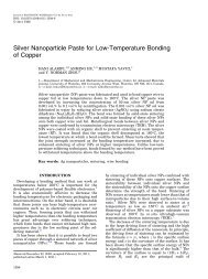
SEM images <strong>of</strong> the inter-critical HAZ (experiencing temperatures<br />
between Ac 1 <strong>and</strong> Ac 3 lines) with adjacent BM <strong>and</strong> upper-critical HAZ<br />
(region above Ac 3 line) <strong>of</strong> HSLA joint are shown in Fig. 3. The HSLA<br />
BM microstructure (Fig. 3b was confirmed to consist <strong>of</strong> ferrite grains<br />
with finely dispersed alloy carbide particles as observed in optical<br />
image (Fig. 2c). Fig. 3c represented the microstructure containing<br />
some martensite which formed as a product <strong>of</strong> fast cooling from<br />
the inter-critical region, where the partially formed austenite (i.e.,<br />
co-existence <strong>of</strong> ferrite <strong>and</strong> austenite) transformed to martensite<br />
during fast cooling down to room temperature in the FLW process.<br />
However, it should be pointed out that the HAZ <strong>of</strong> HSLA joint did not<br />
involve any microstructural changes at the sub-critical region (be<strong>low</strong><br />
Ac 1 line) due to the absence <strong>of</strong> martensite in its BM.<br />
On the other h<strong>and</strong>, for DP980 steel after FLW a tempered martensite<br />
area (or sub-critical region be<strong>low</strong> Ac 1 line) located in-between<br />
the BM <strong>and</strong> inter-critical zone (between Ac 1 <strong>and</strong> Ac 3<br />
(b)<br />
b<br />
c<br />
F<br />
BM<br />
Inter-critical HAZ<br />
Uppercritical<br />
HAZ<br />
F<br />
(c)<br />
F<br />
M<br />
Fig. 3. SEM micrographs showing the HAZ microstructure change in the FLW <strong>of</strong> HSLA steel, (a) overall view <strong>of</strong> inter-critical HAZ with adjacent BM <strong>and</strong> upper-critical HAZ, (b)<br />
HSLA BM with ferrite <strong>and</strong> fine alloy carbides, <strong>and</strong> (c) inter-critical HAZ showing newly formed martensite phase (M: martensite, <strong>and</strong> F: ferrite).
W. Xu et al. / Materials <strong>and</strong> Design 43 (2013) 373–383 377<br />
(a)<br />
b<br />
c<br />
(b)<br />
F<br />
M<br />
BM<br />
Tempered<br />
area (subcritical<br />
HAZ)<br />
Intercritical<br />
HAZ<br />
Uppercritical<br />
HAZ<br />
(c)<br />
F<br />
TM<br />
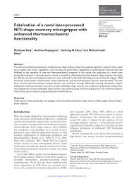
Fig. 4. SEM micrographs showing the microstructural change in a DP980 steel joint, (a) overall view <strong>of</strong> tempered martensite area in the HAZ with adjacent BM, inter-critical<br />
HAZ, <strong>and</strong> upper-critical HAZ, (b) DP980 BM showing ferrite <strong>and</strong> martensite, <strong>and</strong> (c) tempered martensite region in the HAZ (M: martensite, TM: tempered martensite, <strong>and</strong> F:<br />
ferrite).<br />
lines), along with an upper-critical HAZ (above Ac 3 line) could be<br />
seen in Fig. 4a. While the microstructure in the inter-critical zone<br />
was somewhat similar to that in the BM with ferrite plus martensite<br />
isl<strong>and</strong>s, in the tempered martensite area some extent <strong>of</strong> decomposition<br />
<strong>of</strong> the martensite pre-existed in the BM (Fig. 4b) was<br />
clearly visible at a <strong>high</strong>er magnification as shown in Fig. 4c. Tempered<br />
martensite <strong>and</strong> the resultant s<strong>of</strong>tening zone in the <strong>laser</strong><br />
welding <strong>of</strong> DP980 steel have been reported in many earlier studies<br />
[11,13,14,23]. In general, the temperature undergone in the s<strong>of</strong>tening<br />
region during welding was close to or be<strong>low</strong> the critical temperature<br />
(Ac 1 at which austenite begins to form during heating)<br />
which led to <strong>high</strong> temperature tempering <strong>of</strong> martensite phase in<br />
the BM <strong>of</strong> DP steels [11,13,14,20,23–25]. The microstructure <strong>of</strong><br />
tempered martensite in DP980 welds has been reported to consist<br />
typically <strong>of</strong> uniformly distributed fine precipitated cementite<br />
(Fe 3 C) particles embedded within a continuous ferrite matrix<br />
[20,26–28]. As seen from Fig. 4c, it was clear that only partial tempering<br />
<strong>of</strong> martensite occurred in the HAZ <strong>of</strong> DP980 in the FLW<br />
process.<br />
Vickers hardness, HV<br />
600<br />
500 BM HAZ FZ HAZ BM<br />
400<br />
FLW HSLA-S<br />
FLW DP980-S<br />
300<br />
S<strong>of</strong>t zone S<strong>of</strong>t zone<br />
200<br />
100 BM HAZ FZ HAZ BM<br />
0<br />
-6 -4 -2 0 2 4 6<br />
Distance from weld centreline, mm<br />
Fig. 5. Representative hardness pr<strong>of</strong>iles across the HSLA-S <strong>and</strong> DP980-S joints.<br />
3.2. Hardness pr<strong>of</strong>iles<br />
Vickers microhardness pr<strong>of</strong>iles across the welds <strong>of</strong> the FLW<br />
HSLA single linear joint (FLW HSLA-S) <strong>and</strong> the FLW DP980 single<br />
linear joint (FLW DP980-S) (as indicated by the red 1 dashed lines<br />
in Fig 2a <strong>and</strong> b) are showed in Fig. 5. The average hardness value<br />
<strong>of</strong> the HSLA <strong>and</strong> DP980 steel BM was measured to be about<br />
170 HV <strong>and</strong> 340 HV, respectively. The <strong>high</strong>er hardness in the<br />
DP980 BM was attributed to the presence <strong>of</strong> <strong>high</strong>er fraction <strong>of</strong> hard<br />
martensite phase (56%, Fig. 2d <strong>and</strong> Fig. 4b), while the HSLA BM<br />
did not contain any martensite (Fig. 2c <strong>and</strong> Fig. 3b). In accordance<br />
with the microstructure (Fig. 2g <strong>and</strong> h) where fully martensitic<br />
structure emerged, the hardness <strong>of</strong> the FZ became much <strong>high</strong>er<br />
1 For interpretation <strong>of</strong> color in Figs. 2-11, the reader is referred to the web version<br />
<strong>of</strong> this article.<br />
<strong>and</strong> showed a decrease from FZ to the HAZ. Interestingly, the hardness<br />
curve though the whole HAZ was seen to merge smoothly into<br />
the unaffected BM in the HSLA joint due to a decrease in the fraction<br />
<strong>of</strong> martensite in the HAZ which formed as a solid-state phase<br />
transformation from austenite in the inter-critical region. On the<br />
other h<strong>and</strong>, the hardness pattern in the DP980 joint exhibited<br />
two s<strong>of</strong>t zone ‘‘valleys’’ beside the center FZ, where the hardness<br />
locally dropped significantly to an average <strong>of</strong> 280 HV which was<br />
well be<strong>low</strong> the DP980 BM hardness (350 HV). This was attributed<br />
to the occurrence <strong>of</strong> martensite tempering (HAZ-s<strong>of</strong>tened region)<br />
as discussed above <strong>and</strong> also illustrated in Fig. 4. The narrow FZ<br />
with fully martensitic microstructure in both HSLA <strong>and</strong> DP980<br />
joints after FLW were characterized by a very <strong>high</strong> hardness<br />
(Fig. 5). However, the DP980 joint had a further <strong>high</strong>er hardness<br />
averaging 450 HV compared with the average FZ hardness<br />
(360 HV) in the HSLA joint. This was mainly due to the fact that
378 W. Xu et al. / Materials <strong>and</strong> Design 43 (2013) 373–383<br />
Vickers hardness, HV<br />
600<br />
500<br />
400<br />
300<br />
200<br />
100<br />
S<strong>of</strong>t<br />
zone<br />
S<strong>of</strong>t<br />
zone<br />
FLW HSLA-M<br />
FLW DP980-M<br />
S<strong>of</strong>t<br />
zone<br />
0<br />
-4 0 4 8 12 16 20 24<br />
Distance from left weld line, mm<br />
S<strong>of</strong>t<br />
zone<br />
BM HAZ FZ HAZ BM HAZ FZ HAZ BM<br />
observed to display a ‘‘suspension bridge’’-like or ‘‘cable-stayed<br />
bridge’’-like hardness pr<strong>of</strong>ile with two FZ hardness representing<br />
the ‘‘pylons or towers’’. It is seen that each weld bead <strong>of</strong> the multiple<br />
linear joints (Fig. 6) had a similar hardness values when compared<br />
it to the single linear joints (Fig. 5), which was a result <strong>of</strong><br />
similar microstructures as noted in the previous section. The distinction<br />
between the FLW HSLA-M <strong>and</strong> FLW DP980-M joints was<br />
that the hardness pr<strong>of</strong>ile <strong>of</strong> the former was smoother without ‘‘valleys’’<br />
due to the absence <strong>of</strong> HAZ-s<strong>of</strong>tening (martensite tempering).<br />
On the contrary, in the FLW DP980-M joint each FZ hardness ‘‘pylon’’<br />
was accompanied by two s<strong>of</strong>t zone ‘‘valleys’’ positioned at its<br />
two sides (Fig. 6). It would be <strong>of</strong> interest to see if doubling the<br />
number <strong>of</strong> s<strong>of</strong>t zones would affect tensile <strong>strength</strong> <strong>and</strong> <strong>fatigue</strong> life<br />
<strong>of</strong> the HSLA <strong>and</strong> DP980 joints.<br />
3.3. <strong>Tensile</strong> <strong>properties</strong><br />
Fig. 6. Typical hardness pr<strong>of</strong>iles across the HSLA-M <strong>and</strong> DP980-M joints.<br />
Engineering stress, MPa<br />
1200<br />
900<br />
600<br />
300<br />
0<br />
0 5 10 15 20<br />
Engineering strain, %<br />
HSLA BM<br />
FLW HSLA-S<br />
FLW HSLA-M<br />
DP980 BM<br />
FLW DP980-S<br />
FLW DP980-M<br />
Fig. 7. Representative engineering stress versus engineering strain curves <strong>of</strong> HSLA<br />
BM, FLW HSLA-S joint, FLW HSLA-M joint, DP980 BM, FLW DP980-S joint, FLW<br />
DP980-M joint tested at a strain rate <strong>of</strong> 1 10 3 s 1 .<br />
the martensite in the FZ <strong>of</strong> DP980 joint contained a <strong>high</strong>er amount<br />
<strong>of</strong> carbon, as seen in Table 1 where nearly twice carbon content<br />
was present in the DP980 steel compared with the HSLA steel.<br />
Additionally, nearly doubled manganese content in the DP980 steel<br />
(Table 1) also contributed to the <strong>high</strong>er hardness [29]. Calcagnotto<br />
et al. [30] noted that Mn was able to increase hardneability<br />
substantially just like carbon content in austenite on grain size stability<br />
<strong>and</strong> hardneability in ultrafine-grained ferrite/martensite<br />
dual-phase steel.<br />
Fig. 6 shows the microhardness pr<strong>of</strong>iles across the multiple linear<br />
weld <strong>of</strong> FLW HSLA (FLW HSLA-M) <strong>and</strong> FLW DP980 (FLW<br />
DP980-M) joints. Both FLW HSLA-M <strong>and</strong> FLW DP980-M joints were<br />
The representative engineering stress versus engineering strain<br />
curves, determined at a strain rate <strong>of</strong> 1 10 3 s 1 , <strong>of</strong> the BM, FLW<br />
single <strong>and</strong> multiple linear joints <strong>of</strong> both HSLA <strong>and</strong> DP980 steels are<br />
illustrated in Fig. 7. In the HSLA joints, both the strain to failure <strong>and</strong><br />
the yield <strong>strength</strong> (YS) after welding were observed to be very<br />
close to those <strong>of</strong> the BM. The evaluated tensile test results are<br />
listed in Table 3. The YS <strong>and</strong> ultimate tensile <strong>strength</strong> (UTS) were<br />
obtained to be 400 MPa <strong>and</strong> 515 MPa, respectively, for the FLW<br />
HSLA-S joint <strong>and</strong> 398 MPa <strong>and</strong> 523 MPa, respectively, for the<br />
FLW HSLA-M joint. These values were fairly close to those <strong>of</strong> the<br />
BM which had a YS <strong>of</strong> 455 MPa <strong>and</strong> UTS <strong>of</strong> 546 MPa (Table 3, <strong>and</strong><br />
Fig. 7). These tensile results suggested that the present FLW process,<br />
regardless <strong>of</strong> single or multiple linear welding had little influence<br />
on the tensile <strong>properties</strong> <strong>of</strong> the HSLA steel. Obviously, this was<br />
because the FLW <strong>of</strong> HSLA steel did not create any s<strong>of</strong>t zone (Fig. 5<br />
<strong>and</strong> 6) in the HAZ that was detrimental to the mechanical <strong>properties</strong><br />
<strong>of</strong> the welds. This was also corroborated by the tensile failure<br />
<strong>of</strong> FLW HSLA joints that consistently occurred in the BM. This finding<br />
was also in agreement with the earlier observations on the tensile<br />
failure locations by Xia et al. in a DLW HSLA joint [11], Farabi<br />
et al. [31] in a diode <strong>laser</strong> <strong>welded</strong> DP600 steel joint, <strong>and</strong> P<strong>and</strong>a et al.<br />
[32] in a diode <strong>laser</strong> <strong>welded</strong> HSLA/DP980 dissimilar joint with a<br />
thickness <strong>of</strong> 1.14 mm <strong>and</strong> 1.17 mm, respectively.<br />
In contrast to the HSLA welds, the DP980 joints showed a <strong>low</strong>er<br />
strain to failure (Fig. 7 <strong>and</strong> Table 3). However, the YS <strong>and</strong> UTS were<br />
basically unaffected by the FLW. As seen in Table 2, the <strong>strength</strong> <strong>of</strong><br />
FLW DP980-S joints (YS = 719 MPa; UTS = 1048 MPa) <strong>and</strong> FLW<br />
DP980-M joints (YS = 717 MPa, UTS = 1066 MPa) was very close<br />
to those <strong>of</strong> the BM (YS = 720 MPa; UTS = 1095 MPa). The results<br />
indicated that the presence <strong>of</strong> narrow s<strong>of</strong>t zone in the FLW<br />
DP980 welds was not detrimental to the tensile <strong>strength</strong>, <strong>and</strong> the<br />
<strong>high</strong> welding speed could greatly reduce the harmful influence <strong>of</strong><br />
the s<strong>of</strong>t zone by narrowing it down significantly.<br />
It was also <strong>of</strong> interest to observe that a joint efficiency (i.e., a ratio<br />
<strong>of</strong> the UTS <strong>of</strong> <strong>welded</strong> joints to the UTS <strong>of</strong> the corresponding BM<br />
[33–35]) <strong>of</strong> both FLW HSLA joints <strong>and</strong> FLW DP980 joints reached as<br />
<strong>high</strong> as about 94–96% <strong>and</strong> 96–97% (Table 3), respectively. These<br />
Table 3<br />
<strong>Tensile</strong> <strong>properties</strong> <strong>and</strong> <strong>fatigue</strong> parameters r 0 f<br />
<strong>and</strong> b for HSLA BM, FLW HSLA-S joint, FLW HSLA-M joint, DP980 BM, FLW DP980-S joint, <strong>and</strong> FLW DP980-M joint.<br />
Welding type<br />
Yield <strong>strength</strong><br />
(MPa)<br />
Ultimate tensile <strong>strength</strong><br />
(MPa)<br />
Elongation<br />
(%)<br />
Joint efficiency<br />
(%)<br />
Fatigue limit<br />
(MPa)<br />
Fatigue<br />
ratio<br />
r 0 f<br />
(MPa)<br />
b<br />
HSLA BM 455 546 24.7 – 200 0.366 302 0.023<br />
FLW HSLA-S 400 515 22.7 94.3 125 0.243 328 0.041<br />
FLW HSLA-M 398 523 20.7 95.8 125 0.239 343 0.048<br />
DP980 BM 720 1095 14.2 – 250 0.228 1019 0.098<br />
FLW DP980-S 719 1048 4.6 95.7 150 0.143 1169 0.132<br />
FLW DP980-M 717 1066 5.1 97.3 150 0.141 1984 0.185
W. Xu et al. / Materials <strong>and</strong> Design 43 (2013) 373–383 379<br />
results were similar to those <strong>of</strong> Nd:YAG <strong>laser</strong> welding (94.1% for<br />
DP980 steel joints) [12] <strong>and</strong> CO 2 <strong>laser</strong> welding (96.9% for CP1180<br />
steel joints [12]). Indeed, if one considers the ratio <strong>of</strong> the YS <strong>of</strong><br />
<strong>welded</strong> joints to the YS <strong>of</strong> the corresponding BM, a nearly 100%<br />
YS joint efficiency would be achieved in both FLW DP980-S <strong>and</strong><br />
FLW DP980-M joints. From these tensile results it can be concluded<br />
that FLW is an able <strong>and</strong> viable joining process that gave rise to<br />
superior tensile performance approaching that <strong>of</strong> BMs for both<br />
HSLA <strong>and</strong> DP980 steels, while the FLW DP980 joints had a much<br />
<strong>high</strong>er tensile <strong>strength</strong> than the FLW HSLA joints.<br />
However, it should be noted that, while the percent elongation<br />
or ductility <strong>of</strong> both FLW HSLA-S <strong>and</strong> HSLA-M joints (21–23%)<br />
came fairly close to that <strong>of</strong> the HSLA BM (25%) as shown in Table<br />
3, the ductility <strong>of</strong> the FLW DP980-S joints (4.6%) <strong>and</strong> the FLW<br />
DP980-M joints (5.1%) was noticeably <strong>low</strong>er than that <strong>of</strong> the BM<br />
(14.2%) since all the tensile test samples failed consistently in the<br />
s<strong>of</strong>t zone. The <strong>low</strong>er ductility in the DP980 welds was due to the<br />
fact that yielding occurred first in one <strong>of</strong> the s<strong>of</strong>t zones <strong>and</strong> the<br />
subsequent plastic deformation was predominantly concentrated<br />
there leading to necking <strong>and</strong> premature failure at that location,<br />
which resulted in a reduction in the overall specimen elongation.<br />
Similar results have also been reported in the study <strong>of</strong> formability<br />
<strong>of</strong> DLW <strong>of</strong> DP980 [11,32]. It was also due to the premature failure<br />
induced by the s<strong>of</strong>t zone (i.e., <strong>low</strong>er ductility) that the UTS <strong>of</strong> FLW<br />
joints became <strong>low</strong>er (Fig. 7), although a <strong>high</strong> joint efficiency <strong>of</strong><br />
about 96–97% was achieved in the FLW DP980 joints.<br />
3.4. Fatigue <strong>strength</strong> <strong>and</strong> failure mode<br />
Fatigue test results <strong>of</strong> the BM, FLW single linear <strong>and</strong> multiple<br />
linear joints <strong>of</strong> HSLA tested at R = 0.1, 50 Hz, <strong>and</strong> room temperature<br />
(RT) are plotted in the Fig. 8a. Both FLW HSLA-S <strong>and</strong> HSLA-M joints<br />
exhibited an equivalent <strong>fatigue</strong> life within the experimental scatter.<br />
At a stress amplitude <strong>of</strong> above 250 MPa the <strong>fatigue</strong> life <strong>of</strong> the<br />
joints was only slightly <strong>low</strong>er than that <strong>of</strong> the BM, whereas the <strong>fatigue</strong><br />
<strong>strength</strong> became <strong>low</strong>er <strong>and</strong> more scattered at <strong>low</strong>er stress<br />
amplitudes (
380 W. Xu et al. / Materials <strong>and</strong> Design 43 (2013) 373–383<br />
stress amplitudes increased with increasing number <strong>of</strong> s<strong>of</strong>t zones<br />
in the <strong>high</strong>er grade <strong>of</strong> DP980.<br />
To make a better comparison, <strong>fatigue</strong> test results <strong>of</strong> the FLW<br />
HSLA-S joints, the FLW HSLA-M joints, the FLW DP980-S joints,<br />
<strong>and</strong> the FLW DP980-M joints were plotted in Fig. 8c. The FLW<br />
DP980 joints were observed to have a much <strong>high</strong>er <strong>fatigue</strong> <strong>strength</strong><br />
than that <strong>of</strong> the FLW HSLA joints at a stress amplitude above<br />
250 MPa, but the <strong>fatigue</strong> <strong>strength</strong> was equivalent be<strong>low</strong> a stress<br />
amplitude <strong>of</strong> 250 MPa for both DP980 <strong>and</strong> HSLA joints due to the<br />
fact that the <strong>high</strong>er grade/<strong>strength</strong> <strong>of</strong> DP980 was more sensitive<br />
to the presence <strong>of</strong> severe weld concavity (Fig. 2b) especially at<br />
the <strong>low</strong>er level <strong>of</strong> cyclic load than at the <strong>high</strong>er level <strong>of</strong> cyclic load.<br />
Fatigue limit <strong>and</strong> <strong>fatigue</strong> ratio are tabulated in Table 3. The decrease<br />
in <strong>fatigue</strong> limit for both FLW HSLA <strong>and</strong> FLW DP980 joints,<br />
with respect to their BM, were similar at 37.5% <strong>and</strong> 40%, respectively,<br />
while the <strong>fatigue</strong> limit <strong>of</strong> the FLW DP980 joints were 20%<br />
<strong>high</strong>er than that <strong>of</strong> the FLW HSLA joints. The <strong>fatigue</strong> ratio (i.e., a ratio<br />
<strong>of</strong> <strong>fatigue</strong> limit to the UTS) <strong>of</strong> the FLW HSLA-S joints <strong>and</strong> the<br />
FLW DP980-S joints were 0.243 <strong>and</strong> 0.143, respectively. The <strong>low</strong>er<br />
<strong>fatigue</strong> ratio <strong>of</strong> FLW DP980-S joints was related to its much <strong>high</strong>er<br />
(or twice) UTS (Table 3). These results suggested that while the<br />
tensile <strong>strength</strong> <strong>of</strong> the FLW DP980 joints was much <strong>high</strong>er than<br />
that <strong>of</strong> the FLW HSLA joints, the <strong>fatigue</strong> <strong>strength</strong> was very close<br />
for both joints at a <strong>low</strong>er level <strong>of</strong> stress amplitudes (
W. Xu et al. / Materials <strong>and</strong> Design 43 (2013) 373–383 381<br />
in both joints was similar to a notched specimen studied by Chapetti<br />
et al. [38] where the stress concentration was generated,<br />
<strong>and</strong> consequently a decreased <strong>fatigue</strong> limit or <strong>fatigue</strong> life at the<br />
<strong>low</strong> level <strong>of</strong> stress amplitudes was observed. Further studies are<br />
needed to eliminate the weld concavity <strong>and</strong> improve the <strong>fatigue</strong><br />
resistance.<br />
The obtained <strong>fatigue</strong> data plotted in Fig. 8 could be fitted using<br />
the fol<strong>low</strong>ing Basquin type equation,<br />
r a ¼ r 0 f ð2NÞb<br />
where r a is the stress amplitude, r 0 f<br />
is the <strong>fatigue</strong> <strong>strength</strong> coefficient<br />
defined by the stress intercept at 2N =1,N is the number <strong>of</strong><br />
cycle to failure, <strong>and</strong> b is the <strong>fatigue</strong> <strong>strength</strong> exponent. The obtained<br />
values <strong>of</strong> r 0 f<br />
<strong>and</strong> b <strong>of</strong> the BM, the FLW single linear joint <strong>and</strong> the FLW<br />
multiple linear joints for both HSLA <strong>and</strong> DP980 steels tested at<br />
R = 0.1, 50 Hz <strong>and</strong> room temperature are given in Table 3. Apparently,<br />
the <strong>fatigue</strong> life at a given stress amplitude was dependent<br />
on both <strong>fatigue</strong> <strong>strength</strong> coefficient r 0 f<br />
<strong>and</strong> <strong>fatigue</strong> <strong>strength</strong> exponent<br />
b with b being a predominant factor. The smaller the absolute<br />
value <strong>of</strong> b, the longer the <strong>fatigue</strong> life. It is seen from Table 3 that<br />
after FSW for both HSLA <strong>and</strong> DP980 steels the absolute values <strong>of</strong><br />
b became larger, giving rise to a <strong>low</strong>er <strong>fatigue</strong> life after welding.<br />
3.5. Failure location <strong>and</strong> fractography<br />
The typical <strong>fatigue</strong> failure locations for the HSLA-S joints, the<br />
HSLA-M joints, the DP980-S joints <strong>and</strong> the DP980-M joints are<br />
shown in Fig. 9. It is seen that the <strong>fatigue</strong> failure for the FLW HSLA<br />
joints occurred in the BM with large deformation at a stress amplitude<br />
above 250 MPa (Fig. 9a <strong>and</strong> b), whereas it occurred at HAZ be<strong>low</strong><br />
a stress amplitude <strong>of</strong> 250 MPa (Fig. 9c <strong>and</strong> d), irrespective <strong>of</strong><br />
the single or multiple linear welding. It was believed that while<br />
ð1Þ<br />
the weld concavity in the FLW HSLA joints (Fig. 2a) did not significantly<br />
influence the tensile <strong>strength</strong> (Fig. 7 <strong>and</strong> Table 3), the <strong>fatigue</strong><br />
<strong>strength</strong> at the condition <strong>of</strong> stress amplitude be<strong>low</strong> 250 MPa<br />
was affected adversely. In contrast, the <strong>fatigue</strong> failure in the FLW<br />
DP980 joints always initiated in weld concavity (Fig. 9e <strong>and</strong> f)<br />
due to the presence <strong>of</strong> stress concentration, <strong>and</strong> then propagated<br />
in the s<strong>of</strong>t zone (Fig. 5 <strong>and</strong> 6). The failure location <strong>of</strong> the FLW joints<br />
was similar to that <strong>of</strong> the DLW DP980 joints in which all the <strong>fatigue</strong><br />
failure occurred at the s<strong>of</strong>t zones as reported in our earlier study<br />
[39].<br />
SEM images <strong>of</strong> a fracture surface <strong>of</strong> a FLW HSLA-S joint tested at<br />
an applied stress amplitude <strong>of</strong> 200 MPa is shown in Fig. 10. The<br />
cross section in Fig 10a indicated that the <strong>fatigue</strong> test sample experienced<br />
a large deformation before the final fast crack propagation<br />
because <strong>of</strong> the superior ductility <strong>of</strong> HSLA steel in comparison with<br />
DP980 steel (Table 3). It was also confirmed from Fig. 10a <strong>and</strong> b<br />
that crack initiation occurred from the weld concavity (Fig. 2a),<br />
corresponding well to the top view <strong>of</strong> the failed samples (Fig. 9c<br />
<strong>and</strong> d). A magnified SEM image near the crack initiation site is<br />
shown in Fig. 10b, where the crack initiated from the weld concavity<br />
could clearly be seen when the applied stress amplitude was<br />
be<strong>low</strong> 250 MPa. Fatigue crack propagation was mainly characterized<br />
by the formation <strong>of</strong> fairly typical <strong>fatigue</strong> striations in conjunction<br />
with secondary cracks, as shown in Fig. 10c, while the final fast<br />
propagation area consisted <strong>of</strong> distinctive dimples (Fig. 10d). Fatigue<br />
striations basically occurred through a repeated plastic blunting–sharpening<br />
process via the slip <strong>of</strong> dislocations in the plastic<br />
zone in front <strong>of</strong> the <strong>fatigue</strong> crack tip [40].<br />
SEM images <strong>of</strong> a fracture surface <strong>of</strong> a FLW DP980-S joint tested<br />
at an applied stress amplitude <strong>of</strong> 200 MPa is shown in Fig. 11. Itis<br />
from Fig. 11a that multiple crack initiation occurred from the weld<br />
concavity where the surface welding defect occurs (Fig. 11b) as<br />
indicated by the arrow in the image. These characteristics <strong>of</strong> the<br />
(a)<br />
b<br />
d<br />
1 mm<br />
(b)<br />
(c)<br />
c<br />
Surface defect<br />
(d)<br />
Fig. 11. Typical SEM images <strong>of</strong> <strong>fatigue</strong> fracture surface <strong>of</strong> a FLW DP980-S joint tested at a stress amplitude 200 MPa, (a) overall view, (b) crack initiation area, (c) crack<br />
propagation area, <strong>and</strong> (d) final fast crack propagation area.
382 W. Xu et al. / Materials <strong>and</strong> Design 43 (2013) 373–383<br />
<strong>fatigue</strong> fractograph were similar to those observed on the <strong>fatigue</strong><br />
fracture surface reported for a FLW AZ31B-H24 Mg alloy [35].<br />
The <strong>fatigue</strong> crack initiation in the present FLW DP980 steel would<br />
primarily be related to the stress concentration caused by the severe<br />
weld concavity (Fig. 2b), in combination with the presence<br />
<strong>of</strong> detrimental s<strong>of</strong>t zones (Fig. 5 <strong>and</strong> 6). Like the HSLA welds, <strong>fatigue</strong><br />
crack propagation in the FLW DP980 joints was also characterized<br />
by the occurrence <strong>of</strong> <strong>fatigue</strong> striations along with secondary<br />
cracks, as shown in Fig. 11c, whereas the final fast propagation area<br />
consisted <strong>of</strong> characteristic dimples as well, as shown in Fig. 11d,<br />
where some remaining inclusions located at the bottom <strong>of</strong> dimples<br />
could be seen.<br />
4. Conclusions<br />
In this study the microstructure, hardness pr<strong>of</strong>ile, tensile <strong>properties</strong>,<br />
<strong>and</strong> <strong>fatigue</strong> performance <strong>of</strong> <strong>high</strong> speed <strong>fiber</strong> <strong>laser</strong> <strong>welded</strong><br />
HSLA <strong>and</strong> DP980 steel joints with single linear <strong>and</strong> multiple linear<br />
welds are evaluated <strong>and</strong> compared. The fol<strong>low</strong>ing conclusions can<br />
be drawn:<br />
(1) Single phase microstructure containing martensite formed<br />
in the FZ <strong>of</strong> all the joints; however, newly formed martensite<br />
<strong>and</strong> partially tempered martensite structure was observed in<br />
the (HAZ) <strong>of</strong> HSLA <strong>and</strong> DP980 steels, respectively.<br />
(2) The HSLA joints exhibited a hardness pr<strong>of</strong>ile with HAZ hardness<br />
merging smoothly into the unaffected BM values, while<br />
the DP980 joints showed a significant drop <strong>of</strong> hardness in<br />
the HAZ. Despite the formation <strong>of</strong> fully martensitic structure<br />
in the FZ, the <strong>high</strong>er carbon content in DP980 steel resulted<br />
in a <strong>high</strong>er FZ hardness (450 HV) compared to HSLA steel<br />
(360 HV). A characteristic ‘‘suspension bridge’’-like<br />
hardness pr<strong>of</strong>ile with the FZ hardness as a ‘‘pylon’’ was<br />
observed.<br />
(3) Both the HSLA <strong>and</strong> DP980 joints showed a superior tensile<br />
<strong>strength</strong> with a joint efficiency reaching about 94–97%.<br />
While the ductility <strong>of</strong> DP980 joints decreased, the ductility<br />
<strong>of</strong> HSLA joints was fairly close to that <strong>of</strong> BM. Despite<br />
the presence <strong>of</strong> the s<strong>of</strong>t zone, the ultimate tensile<br />
<strong>strength</strong> <strong>of</strong> the DP980 joints was twice <strong>high</strong>er than that<br />
<strong>of</strong> the HSLA joints, which corresponded well to the hardness<br />
results.<br />
(4) The DP980 joints had a much longer <strong>fatigue</strong> life compared to<br />
the HSLA joints at a stress amplitude above 250 MPa; however,<br />
be<strong>low</strong> this stress amplitude both the DP980 <strong>and</strong> HSLA<br />
joints showed a similar <strong>fatigue</strong> life.<br />
(5) No significant effect <strong>of</strong> weld geometry on the <strong>fatigue</strong> life <strong>of</strong><br />
HSLA joints was observed. On the other h<strong>and</strong>, the <strong>fatigue</strong> life<br />
for the multiple linear DP980 joints exhibited a larger scatter<br />
<strong>and</strong> also <strong>low</strong>er <strong>fatigue</strong> <strong>strength</strong>, indicating that the probability<br />
<strong>of</strong> dynamic <strong>fatigue</strong> failure at the <strong>low</strong>er level <strong>of</strong> stress<br />
amplitudes increased with increasing number <strong>of</strong> s<strong>of</strong>t zone<br />
<strong>and</strong> weld concavity in the weld.<br />
(6) Above a stress amplitude <strong>of</strong> 250 MPa, <strong>fatigue</strong> failure <strong>of</strong> the<br />
HSLA joints occurred in the BM, signifying a superior structural<br />
integrity <strong>of</strong> the <strong>fiber</strong> <strong>laser</strong> <strong>welded</strong> HSLA joints when<br />
subjected to <strong>high</strong>er levels <strong>of</strong> cyclic loading. When the<br />
applied stress amplitude was be<strong>low</strong> 250 MPa, <strong>fatigue</strong> failure<br />
occurred from the weld concavity.<br />
(7) In the DP980 joints under both <strong>high</strong>er <strong>and</strong> <strong>low</strong>er levels <strong>of</strong><br />
cyclic loading, <strong>fatigue</strong> crack was observed to initiate predominantly<br />
from the weld concavity <strong>and</strong> propagate in the<br />
s<strong>of</strong>t zone. Fatigue crack propagation in both HSLA <strong>and</strong><br />
DP980 joints was characterized by the characteristic <strong>fatigue</strong><br />
striations coupled with secondary cracks.<br />
Acknowledgements<br />
The authors would like to thank the Natural Sciences <strong>and</strong> Engineering<br />
Research Council <strong>of</strong> Canada (NSERC) <strong>and</strong> AUTO21 Network<br />
<strong>of</strong> Centers <strong>of</strong> Excellence for providing financial support. The financial<br />
support from International Zinc Association (IZA) <strong>and</strong> Arcelor-<br />
Mittal D<strong>of</strong>asco is <strong>high</strong>ly acknowledged. One <strong>of</strong> the authors (D.L.<br />
Chen) is grateful for the financial support by the Premier’s Research<br />
Excellence Award (PREA), NSERC-Discovery Accelerator<br />
Supplement (DAS) Award, Canada Foundation for Innovation<br />
(CFI), <strong>and</strong> Ryerson Research Chair (RRC) program. The authors<br />
would like to thank Dr. J. Chen <strong>and</strong> Dr. Y.L. He (CANMET-Materials<br />
Technology Laboratory, Natural Resources Canada, Hamilton, Canada),<br />
Mr. E. Biro (ArcelorMittal Global Research, Hamilton, Canada),<br />
<strong>and</strong> Dr. J. Villafuerte (CenterLine (Windsor) Ltd., Windsor, Canada)<br />
for their support <strong>and</strong> helpful discussion. The assistance <strong>of</strong> Q. Li, A.<br />
Machin, J. Amankrah, <strong>and</strong> R. Churaman in performing the experiments<br />
is gratefully acknowledged.<br />
References<br />
[1] Howey DA. Policy: a challenging future for cars. Nat Clim Change 2012;2:28–9.<br />
[2] Shindell D, Faluvegi G, Walsh M, Anenberg SC, Dingenen RV, Muller NZ, et al.<br />
Climate, health, agricultural <strong>and</strong> economic impacts <strong>of</strong> tighter vehicle-emission<br />
st<strong>and</strong>ards. Nat Clim Change 2011;1:59–66.<br />
[3] Kim HJ, McMillan C, Keoleian GA, Skerlos SJ. Greenhouse gas emissions<br />
payback for lightweighted vehicles using aluminum <strong>and</strong> <strong>high</strong>-<strong>strength</strong> steel. J<br />
Ind Ecol 2010;14(6):929–46.<br />
[4] Hazratinezhad M, Arab NBM, Sufizadeh AR, Torkamany MJ. Mechanical <strong>and</strong><br />
metallurgical <strong>properties</strong> <strong>of</strong> pulsed neodymium-doped yttrium aluminum<br />
garnet <strong>laser</strong> welding <strong>of</strong> dual phase steels. Mater Des 2012;33:83–7.<br />
[5] Ahmed E, Reisgen U, Schleser M, Mokrov O. On formability <strong>of</strong> tailor <strong>laser</strong><br />
<strong>welded</strong> blanks <strong>of</strong> DP/TRIP steel sheets. Sci Technol Weld Joint 2010;15:<br />
337–42.<br />
[6] Chan LC, Cheng CH, Chan SM, Lee TC, Chow CL. Formability analysis <strong>of</strong> tailor<strong>welded</strong><br />
blanks <strong>of</strong> different thickness ratios. J Manuf Sci E – T ASME<br />
2005;127:743–51.<br />
[7] Quintino L, Costa A, Mir<strong>and</strong>a R, Yapp D, Kumar V, Kong CJ. Welding with <strong>high</strong><br />
power <strong>fiber</strong> <strong>laser</strong>s – a preliminary study. Mater Des 2007;28:1231–7.<br />
[8] Canning J. Fiber <strong>laser</strong>s <strong>and</strong> related technologies. Opt Laser Eng<br />
2006;44:647–76.<br />
[9] Saunders FI, Wagoner RH. Forming <strong>of</strong> tailor-<strong>welded</strong> blanks. Metall Mater Trans<br />
A 1996;27A:2605–16.<br />
[10] Sreenivasan N, Xia M, Lawson S, Zhou Y. Effect <strong>of</strong> <strong>laser</strong> welding on formability<br />
<strong>of</strong> DP980 steel. J Eng Mater T 2008;130:0410041–410049.<br />
[11] Xia M, Sreenivasan N, Lawson S, Zhou Y, Tian Z. A comparative study <strong>of</strong><br />
formability <strong>of</strong> diode <strong>laser</strong> welds in DP980 <strong>and</strong> HSLA steels. J Eng Mater Technol<br />
T A 2007;129:446–52.<br />
[12] Kim CH, Choi JK, Kang MJ, Park YD. A study on the CO 2 <strong>laser</strong> welding<br />
characteristics <strong>of</strong> <strong>high</strong> <strong>strength</strong> steel up to 1500 MPa for automotive<br />
application. J Achiev Mater Manuf Eng 2010;39:79–86.<br />
[13] Farabi N, Chen DL, Zhou Y. Microstructure <strong>and</strong> mechanical <strong>properties</strong> <strong>of</strong> <strong>laser</strong><br />
<strong>welded</strong> dissimilar DP600/DP980 dual-phase steel joints. J Alloy Compd<br />
2011;509:982–9.<br />
[14] Farabi N, Chen DL, Zhou Y. Fatigue <strong>properties</strong> <strong>of</strong> <strong>laser</strong> <strong>welded</strong> dual-phase steel<br />
joints. Procedia Eng 2010;2:835–43.<br />
[15] ASTM E8/E8M-11. St<strong>and</strong>ard test methods for tension testing <strong>of</strong> metallic<br />
materials. ASTM international; 2012.<br />
[16] ASTM E466–07. St<strong>and</strong>ard practice for conducting force controlled constant<br />
amplitude axial <strong>fatigue</strong> tests <strong>of</strong> metallic materials. ASTM international; 2012.<br />
[17] Duley WW. Laser welding. New York: Wiley & Sons, Inc; 1999.<br />
[18] Ready JF, Farson DF. LIA H<strong>and</strong>book <strong>of</strong> <strong>laser</strong> materials processing. Laser Institute<br />
<strong>of</strong> America; 2001.<br />
[19] Xia MS, Kuntz ML, Tian ZL, Zhou Y. Failure study on <strong>laser</strong> welds <strong>of</strong> dual phase<br />
steel in formability testing. Sci Technol Weld Joint 2008;13(4):378–87.<br />
[20] Baltazar Hern<strong>and</strong>ez VH, Nayak SS, Zhou Y. Tempering <strong>of</strong> martensite in dualphase<br />
steels <strong>and</strong> its effects on s<strong>of</strong>tening behavior. Metall Mater Trans A<br />
2011;42A:3115–29.<br />
[21] Huang T, Sato YS, Kokawa H, Miles MP, Kohkonen K, Siemssen B, et al.<br />
Microstructural evolution <strong>of</strong> DP980 steel during friction bit joining. Metall<br />
Mater Trans A 2009;40A:2994–3000.<br />
[22] Kou S. Welding metallurgy. 2nd ed. Hoboken, NJ: John Wiley & Sons Inc; 2003.<br />
[23] Farabi N, Chen DL, Zhou Y. <strong>Tensile</strong> <strong>properties</strong> <strong>and</strong> work hardening behavior <strong>of</strong><br />
<strong>laser</strong> <strong>welded</strong> dual-phase steel joints. J Mater Eng Perform 2012;21(2):<br />
222–30.<br />
[24] Xia M, Biro E, Tian ZL, Zhou Y. Effects <strong>of</strong> heat input <strong>and</strong> martensite on HAZ<br />
s<strong>of</strong>tening in <strong>laser</strong> welding <strong>of</strong> dual phase steels. ISIJ Int 2008;48(6):809–14.<br />
[25] Biro E, McDermid JR, Embury JD, Zhou Y. S<strong>of</strong>tening kinetics in the subcritical<br />
heat-affected zone <strong>of</strong> dual-phase steel welds. Metall Mater Trans A<br />
2010;41(9):2348–56.
W. Xu et al. / Materials <strong>and</strong> Design 43 (2013) 373–383 383<br />
[26] Kuang S, Kang YL, Yu H, Liu RD. Effect <strong>of</strong> continuous annealing parameters on<br />
the mechanical <strong>properties</strong> <strong>and</strong> microstructures <strong>of</strong> a cold rolled dual phase<br />
steel. Int J Min Met Mater 2009;16(2):159–64.<br />
[27] Dancette S, Massardier-Jourdan V, Fabregue D, Merlin J, Dupuy T, Bouzekri M.<br />
HAZ microstructures <strong>and</strong> local mechanical <strong>properties</strong> <strong>of</strong> <strong>high</strong> <strong>strength</strong> steels<br />
resistance spot welds. ISIJ Int 2011;51(1):99–107.<br />
[28] Waterschoot T, Verbeken K, De Cooman BC. Tempering kinetics <strong>of</strong> the<br />
martensitic phase in DP steel. ISIJ Int 2006;46(1):138–46.<br />
[29] Grange RA. Estimating the hardneability <strong>of</strong> carbon steels. Metall Trans<br />
1973;4:2231–44.<br />
[30] Calcagnotto M, Ponge D, Raabe D. On the effect <strong>of</strong> manganese on grain size<br />
stability <strong>and</strong> hardneability in ultrafine-grained ferrite/martensite dual-phase<br />
steels. Metall Mater Trans A 2012;43:37–46.<br />
[31] Farabi N, Chen DL, Li J, Zhou Y, Dong SJ. Microstructure <strong>and</strong> mechanical<br />
<strong>properties</strong> <strong>of</strong> <strong>laser</strong> <strong>welded</strong> DP600 steel joints. Mater Sci Eng A<br />
2010;527:1215–22.<br />
[32] P<strong>and</strong>a SK, Baltazar Hern<strong>and</strong>ez VH, Kuntz ML, Zhou Y. Formability analysis <strong>of</strong><br />
diode-<strong>laser</strong>-<strong>welded</strong> tailored blanks <strong>of</strong> advanced <strong>high</strong>-<strong>strength</strong> steel sheets.<br />
Metall Mater Trans A 2009;40A:1955–67.<br />
[33] Chowdhury SM, Chen DL, Bhole SD, Powidajko E, Weckman DC, Zhou Y.<br />
Microstructure <strong>and</strong> mechanical <strong>properties</strong> <strong>of</strong> <strong>fiber</strong>–<strong>laser</strong> <strong>welded</strong> <strong>and</strong> diode–<br />
<strong>laser</strong>-<strong>welded</strong> AZ31 magnesium alloy. Metall Mater Trans A 2011;42A:<br />
1974–89.<br />
[34] Chowdhury SM, Chen DL, Bhole SD, Cao X, Powidajko E, Weckman DC, et al.<br />
<strong>Tensile</strong> <strong>properties</strong> <strong>and</strong> strain hardening behavior <strong>of</strong> double-sided arc <strong>welded</strong><br />
<strong>and</strong> friction stir <strong>welded</strong> AZ31B magnesium alloy. Mater Sci Eng A<br />
2010;527:2951–61.<br />
[35] Chowdhury SH, Chen DL, Bhole SD, Powidajko E, Weckman DC, Zhou Y. Fiber<br />
<strong>laser</strong> <strong>welded</strong> AZ31 magnesium alloy: effect <strong>of</strong> welding speed on<br />
microstructure <strong>and</strong> mechanical <strong>properties</strong>. Metall Mater Trans A<br />
2012;43A:2133–47.<br />
[36] An<strong>and</strong> D, Chen DL, Bhole SD, Andreychuck P, Boudreau G. Fatigue behaviour <strong>of</strong><br />
tailor (<strong>laser</strong>)-<strong>welded</strong> blanks for automotive applications. Mater Sci Eng A<br />
2006;420:199–207.<br />
[37] Roesler J, Harders H, Baeker M. Mechanical behavior <strong>of</strong> engineering materials:<br />
metals, ceramics, polymers, <strong>and</strong> composites. 1st ed. New York: Springer;<br />
2007.<br />
[38] Chapetti MD, Katsura N, Tagawa T, Miyata T. Static <strong>strength</strong>ening <strong>and</strong><br />
<strong>fatigue</strong> blunt-notch sensitivity in <strong>low</strong>-carbon steels. Int J Fatigue 2001;23:<br />
207–14.<br />
[39] Khan MS, Bhole SD, Chen DL, Boudreau G, Biro E, Deventer JV. Welding<br />
behavior, microstructure <strong>and</strong> mechanical <strong>properties</strong> <strong>of</strong> dissimilar resistance<br />
spot welds between galvannealed HSLA350 <strong>and</strong> DP600 steels. Sci Technol<br />
Weld Joint 2009;14(7):616–25.<br />
[40] Laird C. Fatigue crack propagation. West Conshohocken, PA: ASTM Spec. Tech.<br />
Publ.; 1967.