Digital Filter Applications - Teledyne LeCroy
Digital Filter Applications - Teledyne LeCroy
Digital Filter Applications - Teledyne LeCroy

You also want an ePaper? Increase the reach of your titles
YUMPU automatically turns print PDFs into web optimized ePapers that Google loves.
<strong>Digital</strong> <strong>Filter</strong> <strong>Applications</strong><br />
Useful <strong>Applications</strong> of the <strong>Digital</strong> <strong>Filter</strong> Package 2 (DFP2)<br />
TECHNICAL BRIEF<br />
June 13, 2013<br />
Summary<br />
<strong>Filter</strong>s are useful components<br />
in the analysis of signals in an<br />
oscilloscope. This technical<br />
brief provides examples.<br />
Introduction<br />
<strong>Filter</strong>s are circuits or devices in which the output gain and phase vary as a<br />
function of the frequency of the input. This frequency sensitivity makes<br />
them useful in removing undesirable elements of a signal or<br />
compensating for some frequency dependent distortion within the signal.<br />
<strong>Teledyne</strong> <strong>LeCroy</strong>'s <strong>Digital</strong> <strong>Filter</strong> Package 2 (DFP2) option, for<br />
oscilloscopes, offers a selection of several standard (infinite impulse<br />
response or finite impulse response) filters including low pass, high pass,<br />
band pass or band stop filters or a user defined, custom digital filter<br />
configuration. These can be applied in the analysis and measurement of<br />
waveforms as illustrated in the examples, which follow.<br />
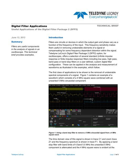
The first class of applications to be shown is the removal of undesirable<br />
spectral components of a signal. Figure 1 contains an example of a<br />
waveform which consists of a 4 MHz square wave combined with an<br />
unwanted 5 MHz sinusoidal component.<br />
Figure 1: Using a band stop filter to remove a 5 MHz sinusoidal signal from a 4 MHz<br />
square wave<br />
The time domain view of this signal is shown in trace C1 and zoom trace<br />
Z1 and the frequency spectrum is shown in trace F1. By applying a band<br />
stop filter with band limits of 4.5and 5.5 MHz the unwanted 5 MHz<br />
component is attenuated and the 4 MHz square wave is evident at the<br />
<strong>Teledyne</strong> <strong>LeCroy</strong> <strong>Digital</strong> <strong>Filter</strong> <strong>Applications</strong> page | 1 of 3
filtered output (Trace F2 and Zoom Z2). The spectrum of the filter output (Trace F3) shows the reduction in the 5<br />
MHz component.<br />
Figure 2 shows how a high pass filter is used to eliminate 60 Hz pickup from a 63 kHz pulse width modulated<br />
signal. The high pass filter is set to attenuate signals lower than 200 Hz thereby removing the 60 Hz signal.<br />
Figure 2: Using a high pass filter to eliminate 60 Hz pickup<br />
If the acquired signal has a shaped baseline, as shown in Figure 3, it is possible to use a low pass filter to<br />
separate the baseline and then subtract it from the acquired waveform. In this example a low pass filter (Trace<br />
F2) is used to extract the baseline which is then subtracted from the acquired signal (C1) in trace F3.<br />
Figure 3: Removing baseline shaping by separating and subtracting the low frequency content of an acquired waveform<br />
<strong>Teledyne</strong> <strong>LeCroy</strong> <strong>Digital</strong> <strong>Filter</strong> <strong>Applications</strong> page | 2 of 3
The last of our spectral separation examples, Figure 4, shows the use of a low pass filter in a detector simulation.<br />
Modulation from an amplitude modulated signal is extracted by peak detection and filtering. The absolute value<br />
function performs full wave peak detection and the DFP 2 option provides the necessary low pass filtering to<br />
remove the residual carrier form the detected waveform.<br />
Figure 4: Using peak detection and filtering to demodulate an AM signal<br />
These examples provide a sense of how the DFP2 filters can be applied to aid your analysis.<br />
<strong>Teledyne</strong> <strong>LeCroy</strong> <strong>Digital</strong> <strong>Filter</strong> <strong>Applications</strong> page | 3 of 3