Data sheet for compact linear actuators CM03 - SCHIEBEL
Data sheet for compact linear actuators CM03 - SCHIEBEL
Data sheet for compact linear actuators CM03 - SCHIEBEL

Create successful ePaper yourself
Turn your PDF publications into a flip-book with our unique Google optimized e-Paper software.
<strong>SCHIEBEL</strong><br />
<strong>actuators</strong>.schiebel.com<br />
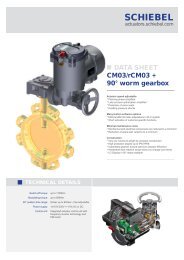
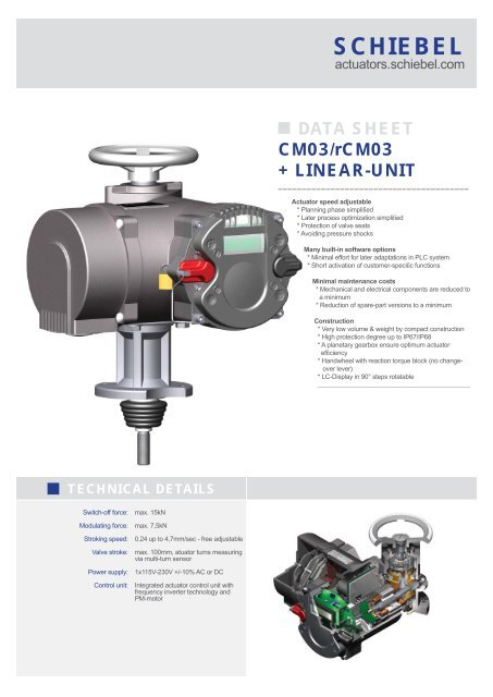
DATA SHEET<br />
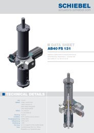
<strong>CM03</strong>/r<strong>CM03</strong><br />
+ LINEAR-UNIT<br />
________________________________________<br />
Actuator speed adjustable<br />
* Planning phase simplified<br />
* Later process optimization simplified<br />
* Protection of valve seats<br />
* Avoiding pressure shocks<br />
Many built-in software options<br />
* Minimal ef<strong>for</strong>t <strong>for</strong> later adaptations in PLC system<br />
* Short activation of customer-specific functions<br />
Minimal maintenance costs<br />
* Mechanical and electrical components are reduced to<br />
a minimum<br />
* Reduction of spare-part versions to a minimum<br />
Construction<br />
* Very low volume & weight by <strong>compact</strong> construction<br />
* High protection degree up to IP67/IP68<br />
* A planetary gearbox ensure optimum actuator<br />
efficiency<br />
* Handwheel with reaction torque block (no changeover<br />
lever)<br />
* LC-Display in 90° steps rotatable<br />
___________________________________________<br />
TECHNICAL DETAILS<br />
Switch-off <strong>for</strong>ce:<br />
Modulating <strong>for</strong>ce:<br />
Stroking speed:<br />
Valve stroke:<br />
Power supply:<br />
Control unit:<br />
max. 15kN<br />
max. 7,5kN<br />
0,24 up to 4,7mm/sec - free adjustable<br />
max. 100mm, atuator turns measuring<br />
via multi-turn sensor<br />
1x115V-230V +/-10% AC or DC<br />
Integrated actuator control unit with<br />
frequency inverter technology and<br />
PM-motor
COMPACT MULTI-TURN ACTUATOR <strong>CM03</strong> / r<strong>CM03</strong> with LINEAR-UNIT<br />
Technical data<br />
TYPE<br />
On/Off duty <strong>CM03</strong> + L50 <strong>CM03</strong> + L100<br />
Modulating duty r<strong>CM03</strong> + L50 r<strong>CM03</strong> + L100<br />
Switch-off <strong>for</strong>ce, adjustable max. kN 15 15<br />
min. kN 4 4<br />
Modulating <strong>for</strong>ce with rCM3 max. kN 7,5 7,5<br />
Travel speed mm / sec 0,24 up to 4,7- free adjustable 0,24 up to 4,7- free adjustable<br />
Stroke max. 50mm 100mm<br />
Operation mode On/Off duty On/Off duty S2-15minutes<br />
Modulating duty<br />
Modulating duty S4 - 1200cycles/hour - 40% duty cycle<br />
Manual operation switching free, overlayed, without lever<br />
Valve-mounting<br />
Flange F10 nach ISO 5210<br />
Spindle end work M16 x 1,5<br />
Rotation<br />
Spindle of Linear-Unit moves out of casing with clockwise actuator rotation<br />
Operating conditions<br />
Protection degree acc.EN 60 529<br />
IP67<br />
Ambient temperature -25°C bis + 60°C<br />
Corrosion protection<br />
K2 <strong>for</strong> installation in power plants, industries- and waste water plants with aggressive atmosphere<br />
Painting / Colour<br />
2 components painting / RAL7024<br />
Weight 12,5 kg 16,5 kg<br />
Motor<br />
PM-Motor<br />
Isolation class<br />
Isolation class F, max. 155°C permanent temperature<br />
Power supply V 1 x 115V-230V +/- 10%; 50/60Hz AC or DC<br />
Current consumption A ca. 2,25<br />
Power W ca. 250W<br />
Actuator control<br />
Electronic with frequency-technology Integrated processor control unit with frequency-technology <strong>for</strong> variable speed control<br />
Control unit<br />
Control elements<br />
with additional language independent symbols<br />
Selector switch LOCAL - OFF - REMOTE, contact free with GMR-technology (lockable)<br />
Control switch OPEN - STOP - CLOSE, contact free with GMR-technology<br />
Indication<br />
lighted LC-display, Lid with display in 90° steps turnable<br />
Signal lamps<br />
4 LED’s <strong>for</strong> operation-, readiness-, warning- and error-messages<br />
Communication<br />
Infrared communication interface <strong>for</strong> programming and saving operation data<br />
Control<br />
Inputs 5 binary control inputs: OPEN - STOP - CLOSE - EMERGENCY OPEN - EMERCENCY CLOSE -<br />
free parametrizable<br />
Power supply: 24VDC (max. 30VDC) - current consumption with 24VDC: typical 5mA<br />
The common ground of the inputs is optical isolated from the rest of the electronic<br />
Status indication<br />
Outputs 8 binary outputs: READY - OPEN - CLOSE - RUNNING OPEN - RUNNING CLOSE - TORQUE -<br />
LOCAL - REMOTE - free parametrizable<br />
power supply 24VDC +/- 6V (per actuator or through control system)<br />
max. allowed current per output: 50mA (short-circuit-proof)<br />
max. allowed current <strong>for</strong> all outputs with power supplied by actuator: 150mA<br />
max. allowed current <strong>for</strong> all outputs with power supplied by control system: 250mA<br />
All outputs are optical isolated if power is supplied by control system.<br />
Voltage- In- & Ouput<br />
Power supply - external Input power range: 20-30VDC max. current consumption 320mA or 100mA in<br />
current save mode - status indication also in case of a main power supply failure.<br />
Power supply - by actuator Output voltage: typical 22V, max. output current 150mA<br />
Reference ground is the common ground of the control unit and of the analog inputs and outputs<br />
Functions<br />
Standard<br />
Switch-off mode adjustable: travel- or torque dependent, in reference to valve type<br />
Torque/Force adjustable: 25-100% of max. torque/<strong>for</strong>ce<br />
4 intermediate positions between 0 and 100% in both directions parametrizable<br />
Step-mode operation with adjustable step-start, step-stop, running- & break time in both directions<br />
Writing- and reading protection via password<br />
Multi-lingual display indication: German - English - Czech - Russia - Danish, ...<br />
Status indication of binary inputs and outputs and also of the analog signals on LC-display<br />
History data <strong>for</strong> Service-planning and Error-analyses<br />
Motor protection with thermo switches in motor<br />
Electric connection<br />
motor<br />
Industry-screw plug Han6E with 6pols in round plug casing<br />
Control signals<br />
Industry-screw plug Han24E with 24pols in round plug casing<br />
Boreholes <strong>for</strong> cable entries 3 metric threaded boreholes <strong>for</strong> cable glands: M40x1,5 / M32x1,5 / M25x1,5<br />
Important Options<br />
- Protection degee according EN 60 529 IP68 - Analog position indication 0/4-20mA (2-wire)<br />
- proof design according ATEX 94/9/EG - Positioner <strong>for</strong> analog 0/4-20mA input signal from control system<br />
- Bus connection (Profibus DP-V0, DeviceNet, Powerlink) - PID positioner <strong>for</strong> 2 input signals 0/4-20mA (setpoint, external actual value)<br />
- Relay board <strong>for</strong> 250VAC, 2A with 4 or 8 outputs - Signal isolator <strong>for</strong> galvanic isolation of the 0/4-20mA position feedback signal<br />
- Signal isolator <strong>for</strong> galvanic isolation of the 0/4-20mA positioner signal