s7-manual.pdf - Datasensor
s7-manual.pdf - Datasensor
s7-manual.pdf - Datasensor

You also want an ePaper? Increase the reach of your titles
YUMPU automatically turns print PDFs into web optimized ePapers that Google loves.
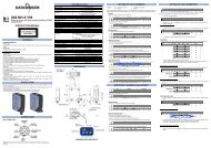
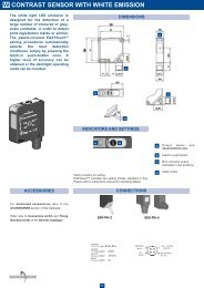
DIMENSIONS<br />
-<br />
OUT S T H Dig1 Dig2 Dig3 Dig4 + SET -<br />
1 9 4 5 • ◦ •<br />
Visualisation of the sensor’s LIGHT/DARK logic switching<br />
OUT S T H Dig1 Dig2 Dig3 Dig4 + SET -<br />
L - O n • ◦ •<br />
S7-1/2/4/5 SERIES<br />
INSTRUCTION MANUAL<br />
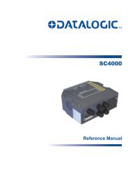
CONTROLS<br />
OUTPUT LED<br />
The yellow LED on indicates that the NO output is closed.<br />
DISPLAY (4 green-coloured digits)<br />
The display indicates the signal level received, the switching threshold and messages relative to the<br />
parameter setting.<br />
Please refer to the “SETTING” paragraph for setup procedure indications.<br />
STABILITY LED (S)<br />
The green stability LED on indicates that the received signal has a safety margin larger than 30% of the<br />
output switching value.<br />
DELAY LED (T)<br />
The green delay LED on indicates that the function is active.<br />
SPEED LED (H)<br />
The green speed LED on indicates that the sensor is functioning with the maximum switching<br />
frequency.<br />
SET PUSHBUTTON<br />
A long pressure on the pushbutton activates the self-setting procedure.<br />
The REMOTE input allows the external SET control.<br />
This pushbutton also allows to set the sensor’s paramters.<br />
+ PUSHBUTTON and - PUSHBUTTON<br />
A long pressure contemporarily on both pushbuttons, gives access to the setting menù of the<br />
parameters.<br />
The switching threshold can be changed pressing the + or – pushbutton.<br />
Please refer to the “SETTING” paragraph for setup procedure indications.<br />
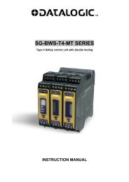
INSTALLATION<br />
The transparent command protection cover rotates<br />
more than 130° in order to have an easy access.<br />
It can be removed opening it completely and pulling it<br />
slightly, with a slight pression it can be replaced back.<br />
Mount the sensor on a DIN rail or using to fixing holes<br />
and screws (M3x20 or longer).<br />
For mounting on DIN rail, insert first part (A).<br />
Fixing holes<br />
Lock button<br />
DIN guide Fibres insertion<br />
holes<br />
Installation of the fibre-optics:<br />
Press the lock pushbutton and keep it pressed until all the fibres has been completely inserted.<br />
Insert the fibres in the corresponding holes as described in the dimension drawing.<br />
The transparent CLEAR-LOCK TM fixing block allows to easily check that the fibres are correctly<br />
inserted.<br />
The insertion resistance is due to the O-ring seal; please insert the fibres for about 6mm deeper until<br />
they touch the photoelements (B).<br />
Fibre-optic<br />
(A)<br />
Lock button<br />
22<br />
10<br />
40<br />
6.5<br />
65 8.5<br />
Ø3.6<br />
21.5 34.6<br />
23.9-25.4<br />
51<br />
STABILITY LED DELAY LED<br />
OUTPUT LED<br />
SPEED LED<br />
DISPLAY<br />
130°<br />
M8<br />
36.5<br />
3.6<br />
SETTING PUSHBUTTON<br />
SET PUSHBUTTON<br />
TECHNICAL DATA<br />
mm<br />
Ø2.4<br />
=<br />
RECEIVER<br />
EMITTER<br />
7.4<br />
18.6<br />
CABLE VERSION<br />
8.5<br />
Power supply: 12 … 24 Vdc ±10%<br />
(reverse polarity protection)<br />
Ripple:<br />
2 Vpp max.<br />
Consumption<br />
(output current excluded):<br />
≤ 50 mA<br />
Outputs:<br />
NPN (S7-x-N) or PNP (S7-x-P)<br />
Output current:<br />
100 mA max.<br />
Output saturation voltage:<br />
≤ 2 V<br />
Response time:<br />
500 µs max. at low speed/100 µs max. at fast speed (S7-2/5)<br />
500 µs max. at low speed/50 µs max. at fast speed (S7-1/4)<br />
Switching frequency:<br />
1 KHz max. at low speed/5KHz. max. at fast speed (S7-2/5)<br />
1 KHz max. at low speed/10KHz. max. at fast speed (S7-1/4)<br />
Indicators:<br />
4 digit DISPLAY (GREEN); OUTPUT LED (YELLOW)<br />
STABILITY LED (GREEN)<br />
DELAY LED (GREEN); SPEED LED (GREEN)<br />
Setting:<br />
SET pushbutton; + pushbutton; - pushbutton<br />
Data retention:<br />
non volatile EEPROM memory<br />
Operating temperature: -10 … 55 °C<br />
Storage temperature: -25 … 70 °C<br />
Electrical protection: Class 2<br />
Operating distance S7-2/5<br />
(typical values):<br />
proximity (with OF-xx-ST fibre): 0…100 mm (with 1KHz)<br />
proximity (with OF-xx-ST fibre):0…50 mm (with 5KHz)<br />
through beam (with OF-xx-ST fibre):0…300 mm (with 1KHz)<br />
through beam (with OF-xx-ST fibre):0…150 mm (with 5KHz)<br />
Operating distance S7-1/4<br />
(typical values):<br />
proximity (with OF-xx-ST fibre): 0…25 mm (with 1KHz/10Hz)<br />
through beam (with OF-xx-ST fibre):0…75 mm (with 1KHz/10KHz)<br />
Emission type:<br />
S7- 2/5 RED (670 nm) / S7-1/4 WHITE (400-700nm)<br />
Ambient light rejection: EN 60947-5-2<br />
Vibrations:<br />
0.5 mm amplitude, 10 … 55 Hz frequency, for every axis<br />
(EN60068-2-6)<br />
Shock resistance:<br />
11 ms (30 G) 6 shock for every axis (EN60068-2-27)<br />
Housing material:<br />
ABS<br />
Mechanical protection:<br />
IP65<br />
Connections:<br />
2 m ∅ 4 mm cable ((S7-1/2)<br />
M8 4-pole connector (S7-4/5)<br />
Weight:<br />
115 g. max. cable vers. / 30 g. max. connector vers.<br />
SETTING<br />
EASY TOUCH<br />
The sensor uses the patent-covered EASY TOUCH technology that allows a rapid and safe selfsetting<br />
of the product.<br />
Two different setting possibilities are available:<br />
- EASY TOUCH; a long pressure of the SET pushbutton allows self-setting.<br />
- FINE DETECTION; to be used only in particularly critical conditions. This setting procedure is used<br />
only when the EASY TOUCH is not sufficient.<br />
• pushbutton pressed ◦ pushbutton not pressed<br />
Ø4<br />
- The switching threshold value begins to blink<br />
- The switching threshold can be changed using the + or – pushbuttons<br />
- The sensor returns to the Normal mode, visualising the received signal, after 5sec.of inactivity<br />
- Fine detection<br />
This mode offers an improved detection precision. The sensor can function either in the DARK<br />
operating or in the LIGHT operating mode.<br />
Place the object to detect in front of the proximity fibres within the operating distance, or in the middle<br />
of the through beam fibres.<br />
Bar Graph Display Keyboard<br />
OUT S T H Dig1 Dig2 Dig3 Dig4 + SET -<br />
1 9 4 5 ◦ • ◦<br />
- Press the SET pushbutton for at least 4sec.<br />
OUT S T H Dig1 Dig2 Dig3 Dig4 + SET -<br />
• S E T 1 ◦ • ◦<br />
- The “SET1” text appears to detect the object’s condition<br />
- The output LED begins to blink releasing the SET pushbutton, The “SET2” text appears.<br />
OUT S T H Dig1 Dig2 Dig3 Dig4 + SET -<br />
• S E T 2 ◦ • ◦<br />
- Remove the object to detect and press the SET pushbutton again<br />
OUT S T H Dig1 Dig2 Dig3 Dig4 + SET -<br />
1 9 4 5 • ◦ •<br />
- If the detection is correct the switching threshold value begins to blink<br />
- The switching threshold can be changed with the + or – pushbutton<br />
- The sensor returns to the Normal mode, visualising the received signal, after 5sec.of inactivity.<br />
OUT S T H Dig1 Dig2 Dig3 Dig4 + SET -<br />
• F A I L ◦ • ◦<br />
- The “FAIL” message appears if the detection is not correct and the output turns off<br />
- The STABILITY LED blinks.<br />
Switching threshold setting<br />
Bar Graph Display Keyboard<br />
OUT S T H Dig1 Dig2 Dig3 Dig4 + SET -<br />
1 9 4 5 • ◦ •<br />
- Press the + or – pushbutton for at least 2sec.<br />
OUT S T H Dig1 Dig2 Dig3 Dig4 + SET -<br />
1 9 4 5 • ◦ •<br />
- The switching threshold value begins to blink.<br />
OUT S T H Dig1 Dig2 Dig3 Dig4 + SET -<br />
1 9 5 3 • ◦ •<br />
- The switching threshold value is changed pressing the + or – pushbutton<br />
- The units change at each pressure<br />
- The digits change if the pressure is maintained<br />
- The display returns to the Normal mode if the pushbuttons are not pressed for at least 5sec.<br />
PARAMETER SETTING<br />
Bar Graph Display Keyboard<br />
OUT S T H Dig1 Dig2 Dig3 Dig4 + SET -<br />
1 9 4 5 • ◦ •<br />
- Pressing contemporilly the + and – pushbuttons 2sec.<br />
OUT S T H Dig1 Dig2 Dig3 Dig4 + SET -<br />
• M E n u ◦ • ◦<br />
- The “Menù” text appears, access to the parameter setting is obtained releasing the buttons<br />
Visualisation of the delay value<br />
By simply pressing the + or – pushbutton, the menù is visualised (onwards and backward) showing the<br />
following:<br />
OUT S T H Dig1 Dig2 Dig3 Dig4 + SET -<br />
• d E L 0 • ◦ •<br />
d E L 1 ◦ • ◦<br />
d E L 2 ◦ • ◦<br />
d - O n ◦ • ◦<br />
At each pressure of the SET pushbutton, the two logic types (LIGHT or DARK) are visualised.<br />
When the LIGHT mode is selected the “L-On” is visualised; “d-On” to select the DARK mode.<br />
The + pushbutton has to be pressed to continue through the setting menù (the – pushbutton to go<br />
backwards).<br />
Visualisation of the display orientation<br />
OUT S T H Dig1 Dig2 Dig3 Dig4 + SET -<br />
D S u P • ◦ •<br />
D S d n ◦ • ◦<br />
At each pressure of the SET pushbutton, the visualisation of the messages on the display is inverted.<br />
The + pushbutton has to be pressed to continue through the setting menù (the – pushbutton to go<br />
backwards).<br />
Visualisation of the display turning off<br />
OUT S T H Dig1 Dig2 Dig3 Dig4 + SET -<br />
D S O n • ◦ •<br />
D S O F ◦ • ◦<br />
At each pressure of the SET pushbutton, the turning off or on of the dislay is visualised.<br />
If “dSOF” is selected the display will be turned off when back to the normal mode and turned on at each<br />
pressure. It will turn off again if not pressed for at least 5 sec.<br />
The + pushbutton has to be pressed to continue through the setting menù (the – pushbutton to go<br />
backwards).<br />
Visualisation of the SAVE parameters set by the user<br />
OUT S T H Dig1 Dig2 Dig3 Dig4 + SET -<br />
S A V E • ◦ •<br />
All the changed values will be memorised by pressing the SET pushbutton and you exit the menù,<br />
returning to the normal mode.<br />
The + pushbutton has to be pressed to continue through the setting menù (the – pushbutton to go<br />
backwards).<br />
Visualization of the parameter RESET with pre-set values<br />
OUT S T H Dig1 Dig2 Dig3 Dig4 + SET -<br />
r S E t • ◦ •<br />
The default parameters are reset when the SET pushbutton is pressed.<br />
The “RESET” text blinks until the pushbutton is pressed.<br />
The sensor returns to function normally when the button is released.<br />
Default parameters: Delay<br />
NO DELAY<br />
Switching frequency<br />
NORM<br />
Switching logic<br />
LIGHT<br />
Orientation<br />
DS_UP<br />
Display<br />
DS_ON<br />
REMOTE FUNCTION<br />
The REMOTE wire connected to +Vdc is equal to pressing the SET pushbutton. The keyboard block is<br />
activated if at the sensor powering the REMOTE wire is connected +Vdc, and thus the SET pushbutton<br />
is no longer active. To deactivate the keyboard block the sensor has to be turned off and then turned on<br />
with the REMOTE wire not connected.<br />
BROWN<br />
BLACK<br />
WHITE<br />
BLUE<br />
+<br />
(B)<br />
CLEAR-LOCK<br />
CONNECTIONS<br />
12… 24 Vdc<br />
OUTPUT<br />
REMOTE<br />
0 V<br />
REMOTE<br />
12 … 24 Vdc<br />
M8 CONNECTOR<br />
(WHITE)<br />
2<br />
4<br />
+ 1 3 -<br />
(BROWN)<br />
OUTPUT<br />
(BLACK)<br />
0 V<br />
(BLUE)<br />
S7 setting<br />
The EASY TOUCH foresees the LIGHT operating mode.<br />
Thus using proximity fibres, the output is closed and the output LED is ON when the object is detected.<br />
Using through beam fibres, the output is closed and the output LED is ON when the object does not<br />
interrupt the beam (i.e. the object is not detected).<br />
- EASY TOUCH (standard detection)<br />
Place the object to detect in front of the proximity fibres within the operating range, or in the middle of<br />
the through beam fibres.<br />
Bar Graph Display Keyboard<br />
OUT S T H Dig1 Dig2 Dig3 Dig4 + SET -<br />
1 9 4 5 ◦ • ◦<br />
- Press the SET pushbutton for at least 2sec.<br />
OUT S T H Dig1 Dig2 Dig3 Dig4 + SET -<br />
E a s y ◦ • ◦<br />
- The “Easy” text appears for EASY TOUCH detection<br />
- The single detection is made releasing the pushbutton<br />
d E L 3 ◦ • ◦<br />
d E L 4 ◦ • ◦<br />
At each pressure of the SET pushbutton, the different levels of the output deactivation delay are<br />
visualised cyclically and the relative delay value is also memorised.<br />
When the “del0” message is visualised, the T LED is off; it is on in all the other levels (del…del3).<br />
The + pushbutton has to be pressed to continue through the setting menù (the – pushbutton to go<br />
backwards).<br />
The delay levels are: 0=no delay; 1=5ms; 2=10ms; 3=20ms; 4=40ms.<br />
Visualisation of the sensor’s switching frequency<br />
OUT S T H Dig1 Dig2 Dig3 Dig4 + SET -<br />
• d E L 0 • ◦ •<br />
n O r M ◦ • ◦<br />
At each pressure of the SET pushbutton, the different levels of the switching frequency are visualised.<br />
When the Fast speed is selected the H LED is on; the H LED is off if the low “NorM” speed is selected.<br />
The + pushbutton has to be pressed to continue through the setting menù (the – pushbutton to go<br />
backwards).<br />
DECLARATION OF CONFORMITY<br />
We DATASENSOR SpA declare under our sole responsibility that these products are conform to the<br />
2004/108 CEE, 73/23 CEE Directives and successive amendments.<br />
WARRANTY<br />
DATASENSOR SpA warrants its products to be free from defects.<br />
DATASENSOR SpA will repair or replace, free of charge, any product found to be defective during the<br />
warranty period of 36 months from the manufacturing date.<br />
This warranty does not cover damage or liability deriving from the improper application of<br />
DATASENSOR products.<br />
DATASENSOR SpA Via Lavino 265<br />
40050 Monte S. Pietro - Bologna - Italy<br />
Tel: +39 051 6765611 Fax: +39 051 6759324<br />
http://www.datasensor.com e-mail: info@datasensor.com<br />
DATASENSOR SpA cares for the environment: 100% recycled paper.<br />
DATASENSOR SpA reserves the right to make modifications and improvements without prior<br />
notification.<br />
826001513 Rev.D
S7-3/6 SERIES<br />
INSTRUCTION MANUAL<br />
CONTROLS<br />
OUTPUT LED<br />
The yellow LED on indicates that the NO output is closed.<br />
READY/ERROR LED<br />
The permanently green LED indicates that the received signal<br />
guarantees a stable output status.<br />
The alternative green and red blinking of the LED indicates a wrong<br />
setting condition.<br />
Please refer to the “SETTING” paragraph for correct for detection or<br />
setup procedure indications.<br />
SET PUSHBUTTON<br />
A long pressure on the pushbutton activates the self-setting procedure.<br />
The REMOTE input allows the external SET control.<br />
INSTALLATION<br />
The transparent command protection cover rotates more than 130° in<br />
order to have an easy access.<br />
Fixing holes<br />
It can be removed opening it<br />
completely and pulling it slightly,<br />
Lock button<br />
with a slight pression it can be<br />
replaced back.<br />
Mount the sensor on a DIN rail or<br />
using to fixing holes and screws<br />
(M3x20 or longer).<br />
For mounting on DIN rail, insert first (A)<br />
part (A).<br />
DIN guide Fibres insertion<br />
Installation of the fibre-optics:<br />
holes<br />
Press the lock pushbutton and<br />
keep it pressed until all the fibres has been completely inserted.<br />
Insert the fibres in the corresponding holes as described in the<br />
dimension drawing.<br />
The transparent CLEAR-LOCK TM fixing block allows to easily check that<br />
the fibres are correctly inserted.<br />
The insertion resistance is due to the O-ring seal; please insert the fibres<br />
for about 6mm deeper until they touch the photoelements (B).<br />
Fibre-optic<br />
Lock button<br />
(B)<br />
CLEAR-LOCK<br />
22<br />
10<br />
40<br />
6.5<br />
CONNECTIONS<br />
DIMENSIONS<br />
65<br />
Ø3.6<br />
21.5 34.6<br />
23.9-25.4<br />
51<br />
130°<br />
OUTPUT LED<br />
READY/ERROR LED<br />
8.5<br />
M8<br />
36.5<br />
3.6<br />
SET PUSHBUTTON<br />
TECHNICAL DATA<br />
M8 CONNECTOR<br />
Ø2.4<br />
=<br />
RECEIVER<br />
EMITTER<br />
7.4<br />
18.6<br />
CABLE VERSION<br />
8.5<br />
Power supply:<br />
12 … 24 Vdc ±10% (reverse polarity protection)<br />
Ripple:<br />
2 Vpp max.<br />
Consumption<br />
(output current excluded):<br />
40 mA<br />
Outputs:<br />
NPN (S7-x-N) or PNP (S7-x-P)<br />
Output current:<br />
100 mA max. at 25°C derating –2mA/°C<br />
Output saturation voltage:<br />
1.2 V max.<br />
Response time:<br />
500 μs max.<br />
Indicators:<br />
OUTPUT LED (YELLOW) and READY/ERROR LED (GREEN/RED)<br />
Setting:<br />
1 SET pushbutton<br />
Data retention:<br />
non volatile EEPROM memory<br />
Operating temperature: -10 … 55 °C<br />
Storage temperature: -25 … 70 °C<br />
Electrical protection: Class 2<br />
Operating distance (typical values):<br />
proximity (with OF-xx-ST fibre optic) 0 … 100 mm<br />
through beam (with OF-xx-ST fibre optic) 0 … 300 mm<br />
Emission type:<br />
red (670 nm)<br />
Ambient light rejection: according to EN 60947-5-2<br />
Vibrations:<br />
0.5 mm amplitude, 10 … 55 Hz frequency, for every axis (EN60068-2-6)<br />
Shock resistance:<br />
11 ms (30 G) 6 shock for every axis (EN60068-2-27)<br />
Housing material:<br />
ABS<br />
Mechanical protection:<br />
IP65<br />
Connections:<br />
2 m ∅ 4 mm cable (S7-3-x) / M8 4-pole M8 connector (S7-6-x)<br />
Weight:<br />
115 g. max. cable vers. / 30 g. max. connector vers.<br />
DELAY FUNCTION<br />
Press the SET pushbutton until the READ/ERROR LED turns off. Keep the SET pushbutton pressed until the READ/ERROR LED begins to blink<br />
green and release it after it turns off.<br />
If the delay function is not activated the READY/ERROR LED begins to blink green with two fast pulses.<br />
If the function is activated the READY/ERROR LED begins to blink green with four fast pulses.<br />
Press the SET pushbutton to change the function status and check that the blinking mode has changed.<br />
If the SET pushbutton is not pressed for at least ten seconds, the sensor will exit automatically from the delay function.<br />
The delay function adds 20ms to the sensor’s ON pulse duration.<br />
mm<br />
Ø4<br />
SETTING<br />
EASY TOUCH<br />
The sensor uses the patent-covered EASY TOUCH technology that<br />
allows a rapid and safe self-setting of the product.<br />
Two different setting possibilities are available:<br />
- EASY TOUCH; a long pressure of the SET pushbutton allows selfsetting.<br />
- FINE DETECTION; to be used only in particularly critical conditions.<br />
This setting procedure is used only when the EASY TOUCH is not<br />
sufficient.<br />
S7 setting<br />
The EASY TOUCH foresees the LIGHT operating mode.<br />
Thus using proximity fibres, the output is closed and the output LED is<br />
ON when the object is detected.<br />
Using through beam fibres, the output is closed and the output LED is<br />
ON when the object does not interrupt the beam (i.e. the object is not<br />
detected).<br />
- EASY TOUCH (standard detection)<br />
Place the object to detect either in front of the proximity fibres within<br />
the operating range, or in the middle of the through beam fibres.<br />
Press the SET pushbutton and keep the pushbutton pressed until the<br />
signalling LED turns green and the READY/ERROR LED turns OFF.<br />
Release the SET pushbutton. The sensor is now ready to detect the<br />
object.<br />
- Fine detection<br />
This mode offers an improved detection precision. The sensor can<br />
function either in the DARK operating or in the LIGHT operating<br />
mode.<br />
1) Place the object to detect in front of the proximity fibres within the<br />
operating distance, or in the middle of the through beam fibres.<br />
Press the SET pushbutton and keep it pressed until the<br />
READY/ERROR LED turns ON.<br />
Keep it pressed until the LED turns off and maintain the pressure<br />
until the signalling LED begins to blink green. The sensor is now<br />
ready for the second setting.<br />
2) Remove the object to detect and press the SET pushbutton again<br />
until the READY/ERROR LED to turn green.<br />
The sensor is now ready to detect very precisely the object.<br />
If the READY/ERROR LED begins to blink red and green, the<br />
setting has failed, as the contrast is insufficient. Thus the setting<br />
procedure has to be repeated.<br />
Following this setting procedure, the sensor functions in the LIGHT<br />
mode with proximity fibres and in the DARK mode with through beam<br />
fibres. To set the sensor in the DARK mode for proximity or LIGHT<br />
mode for through beam, invert the sequence given above.<br />
The operative DARK/LIGHT mode is automatically selected by the<br />
sensor when is used as contrast sensor.<br />
REMOTE FUNCTION<br />
The REMOTE wire connected to +Vdc is equal to pressing the SET<br />
pushbutton. The keyboard block is activated if at the sensor powering<br />
the REMOTE wire is connected +Vdc, and thus the SET pushbutton is<br />
no longer active. To deactivate the keyboard block the sensor has to be<br />
turned off and then turned on with the REMOTE wire not connected.<br />
DECLARATION OF CONFORMITY<br />
We DATASENSOR SpA declare under our sole responsibility that these<br />
products are conform to the 2004/108/CE, 2006/95/CE Directives and<br />
successive amendments.<br />
WARRANTY<br />
DATASENSOR SpA warrants its products to be free from defects.<br />
DATASENSOR SpA will repair or replace, free of charge, any product<br />
found to be defective during the warranty period of 36 months from the<br />
manufacturing date.<br />
This warranty does not cover damage or liability deriving from the<br />
improper application of DATASENSOR products.<br />
DATASENSOR SpA Via Lavino 265<br />
40050 Monte S. Pietro - Bologna - Italy<br />
Tel: +39 051 6765611 Fax: +39 051 6759324<br />
http://www.datasensor.com e-mail: info@datasensor.com<br />
DATASENSOR SpA cares for the environment: 100% recycled paper.<br />
DATASENSOR SpA reserves the right to make modifications and<br />
improvements without prior notification.<br />
826001270 Rev.D
S7-7/8 SERIES<br />
INSTRUCTION MANUAL<br />
CONTROLS<br />
OUTPUT LED<br />
The yellow LED on indicates that the N.O. (normally open)<br />
output is closed.<br />
STABILITY LED<br />
The green LED ON indicates that the received signal has a<br />
reserve greater than 30% compared to the output switching<br />
value.<br />
TRIMMER<br />
The trimmer 12 turns can be used to adjust sensitivity; the<br />
operating distance increases turning the trimmer clockwise.<br />
INSTALLATION<br />
Fixing holes<br />
The transparent command<br />
protection cover rotates more<br />
than 130° in order to have an<br />
easy access.<br />
It can be removed opening it<br />
completely and pulling it slightly,<br />
with a slight pression it can be<br />
replaced back.<br />
(A)<br />
Mount the sensor on a DIN rail or<br />
DIN guide<br />
using to fixing holes and screws<br />
(M3x20 or longer).<br />
For mounting on DIN rail, insert first part (A).<br />
Lock button<br />
Fibres insertion<br />
holes<br />
Installation of the fibre-optics:<br />
Press the lock pushbutton and keep it pressed until all the fibres<br />
has been completely inserted.<br />
Insert the fibres in the corresponding holes as described in the<br />
dimension drawing.<br />
The transparent CLEAR-LOCK TM fixing block allows to easily check<br />
that the fibres are correctly inserted.<br />
The insertion resistance is due to the O-ring seal; please insert the<br />
fibres for about 6mm deeper until they touch the photoelements<br />
(B).<br />
Fibre-optic<br />
Lock button<br />
(B)<br />
CLEAR-LOCK<br />
Cable version<br />
22<br />
10<br />
40<br />
6.5<br />
CONNECTIONS<br />
DIMENSIONS<br />
Ø3.6<br />
21.5 34.6<br />
23.9-25.4<br />
51<br />
STABILITY LED<br />
OUTPUT LED<br />
65 8.5<br />
TRIMMER<br />
130°<br />
M8 connector<br />
M8<br />
TECHNICAL DATA<br />
36.5<br />
3.6<br />
mm<br />
Ø2.4<br />
=<br />
RECEIVER<br />
EMITTER<br />
7.4<br />
18.6<br />
CABLE VERSION<br />
8.5<br />
Power supply:<br />
12 … 24 Vdc ±10% (reverse polarity protection)<br />
Ripple:<br />
2 Vpp max.<br />
Consumption<br />
(output current excluded):<br />
30 mA max. (no load)<br />
Outputs:<br />
NPN (S7-x-N) or PNP (S7-x-P)<br />
Output current:<br />
100 mA max.<br />
Output saturation voltage:<br />
1.2 V max.<br />
Response time:<br />
500 µs max.<br />
Indicators:<br />
OUTPUT LED (YELLOW) and READY/ERROR LED (GREEN/RED)<br />
Setting:<br />
12 multiturn trimmer<br />
Operating temperature: -10 … 55 °C<br />
Storage temperature: -25 … 70 °C<br />
Insulation resistance<br />
between live and dead parts: 20MΩ (minimum,with 500Vdc)<br />
Dielectric strength:<br />
between live and dead parts: AC 500V (50Hz), 1 minute<br />
Operating distance (typical values):<br />
proximity (with OF-xx-ST fibre optic) 0 … 100 mm<br />
through beam (with OF-xx-ST fibre optic) 0 … 300 mm<br />
Emission type:<br />
red (670 nm)<br />
Ambient light rejection: according to EN 60947-5-2<br />
Vibrations:<br />
0.5 mm amplitude, 10 … 55 Hz frequency, for every axis (EN60068-2-6)<br />
Shock resistance:<br />
11 ms (30 G) 6 shock for every axis (EN60068-2-27)<br />
Housing material:<br />
ABS<br />
Mechanical protection:<br />
IP60<br />
Connections:<br />
2 m ∅ 4 mm cable (S7-7-x) / M8 4-pole M8 connector (S7-8-x)<br />
Weight:<br />
115 g. max. cable vers. / 30 g. max. connector vers.<br />
Ø4<br />
SETTING<br />
Setting with OF-43 (P/R fibre-optics)<br />
Position the sensors (fibre terminals) on opposite<br />
sides.<br />
Turn the sensitivity trimmer to maximum: moving the<br />
sensors both vertically and horizontally and determine<br />
the turning on and off points of the yellow LED (OUT)<br />
and then fix the sensors in the middle of the points<br />
defined.<br />
Optimum operation is obtained when both LEDs are<br />
ON.<br />
If necessary, reduce sensitivity using the trimmer, in<br />
order to detect very small targets. In order to improve<br />
alignment, repeat the procedure detailed above whilst<br />
progressively reducing the sensitivity.<br />
Setting with OF-42 (proximity fibre)<br />
Turn the sensitivity trimmer to minimum: the green<br />
LED is ON, the yellow LED is OFF.<br />
Position the target to detect in front of the sensor or of<br />
the fibre terminals. Turn the sensitivity trimmer<br />
clockwise until the yellow LED turns ON.<br />
Remove the target, the yellow LED turns OFF.<br />
DECLARATION OF CONFORMITY<br />
We DATASENSOR SpA declare under our sole responsibility that these<br />
products are conform to the 2004/108/CE, 2006/95/CE Directives and<br />
successive amendments.<br />
WARRANTY<br />
DATASENSOR SpA warrants its products to be free from defects.<br />
DATASENSOR SpA will repair or replace, free of charge, any product<br />
found to be defective during the warranty period of 36 months from the<br />
manufacturing date.<br />
This warranty does not cover damage or liability deriving from the<br />
improper application of DATASENSOR products.<br />
DATASENSOR SpA Via Lavino 265<br />
40050 Monte S. Pietro - Bologna - Italy<br />
Tel: +39 051 6765611 Fax: +39 051 6759324<br />
http://www.datasensor.com e-mail: info@datasensor.com<br />
DATASENSOR SpA cares for the environment: 100% recycled<br />
paper.<br />
DATASENSOR SpA reserves the right to make modifications<br />
and improvements without prior notification.<br />
826002921 Rev.B