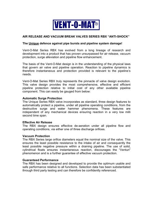
AIR RELEASE AND VACUUM BREAK VALVES SERIES RBX ... - ISF
AIR RELEASE AND VACUUM BREAK VALVES SERIES RBX ... - ISF
AIR RELEASE AND VACUUM BREAK VALVES SERIES RBX ... - ISF

Create successful ePaper yourself
Turn your PDF publications into a flip-book with our unique Google optimized e-Paper software.
<strong>AIR</strong> <strong>RELEASE</strong> <strong>AND</strong> <strong>VACUUM</strong> <strong>BREAK</strong> <strong>VALVES</strong> <strong>SERIES</strong> <strong>RBX</strong> “ANTI-SHOCK”<br />
The Unique defence against pipe bursts and pipeline system damage!<br />
Vent-O-Mat Series <strong>RBX</strong> has evolved from a long lineage of research and<br />
development into a product that has proven unsurpassed for air release, vacuum<br />
protection, surge alleviation and pipeline flow enhancement.<br />
The basis of the Vent-O-Mat design is in the understanding of the physical laws<br />
that govern air valve and pipeline operation. Reaction to pipeline dynamics is<br />
therefore instantaneous and protection provided is relevant to the pipeline’s<br />
needs.<br />
Vent-O-Mat Series <strong>RBX</strong> truly represents the pinnacle of valve design evolution.<br />
This valve design provides the most comprehensive, effective and efficient<br />
pipeline protection relative to initial cost of any other available pipeline<br />
component. This can easily be gauged from below:<br />
Automatic Surge Protection<br />
The Unique Series <strong>RBX</strong> valve incorporates as standard, three design features to<br />
automatically protect a pipeline, under all pipeline operating conditions, from the<br />
destructive surge and water hammer phenomena. These features are<br />
independent of any mechanical devices ensuring reaction in a very low milli<br />
second time span.<br />
Effective Air Release<br />
The <strong>RBX</strong> design ensures effective de-aeration under all pipeline flow and<br />
operating conditions, via either one of three discharge orifices.<br />
Vacuum Protection<br />
The <strong>RBX</strong> Series large orifice diameters equal the nominal size of the valve. This<br />
ensures the least possible resistance to the intake of air and consequently the<br />
least possible negative pressure within a draining pipeline. The use of solid,<br />
cylindrical floats ensures instantaneous reaction, discourages the “Venturi”<br />
phenomenon and is a further guarantee of effective vacuum protection.<br />
Guaranteed Performance<br />
The <strong>RBX</strong> has been designed and developed to provide the optimum usable and<br />
safe performance relative to all functions. Selection data has been substantiated<br />
through third party testing and can therefore be confidently referenced.
The surge protection function of the <strong>RBX</strong> design has been incorporated in the<br />
well-known SURGE 5 surge analysis programmes such as FLOWMASTER and<br />
TRANSAM.<br />
Unparalleled Service<br />
Vent-O-Mat is committed to customer service and to the selling of solutions. Our<br />
highly dedicated team is available at all times to assist with air valve sizing and<br />
positioning. Assistance is also provided in finding the most cost effective and/or<br />
efficient surge protection strategy relevant to the pipeline’s needs.<br />
International Representation<br />
Vent-O-Mat is represented in the following countries and regions:<br />
• USA<br />
• Canada<br />
• Carribean<br />
• United Arab Emirates<br />
• South America<br />
• Thailand<br />
• Germany<br />
• Kenya<br />
• Egypt<br />
• UK<br />
• South Africa<br />
• Zimbabwe<br />
• Tanzania<br />
• Malawi<br />
• Zambia<br />
• Namibia<br />
• Hong Kong<br />
• Taiwan<br />
• New Zealand<br />
• Vietnam<br />
• Kuwait<br />
• Brazil<br />
• France<br />
• Singapore<br />
• Australia
R<br />
CONTENT<br />
Series <strong>RBX</strong><br />
"ANTI - SHOCK"<br />
<strong>AIR</strong> <strong>RELEASE</strong> & <strong>VACUUM</strong> <strong>BREAK</strong> <strong>VALVES</strong><br />
CATALOGUE INDEX<br />
PAGE<br />
OPERATION -<strong>SERIES</strong> <strong>RBX</strong> 1 - 2<br />
RECOMMENDED INSTALLATION ARRANGEMENTS -<strong>SERIES</strong> <strong>RBX</strong> 3<br />
COMPONENT DESCRIPTION & MATERIAL SPECIFICATIONS - <strong>SERIES</strong> <strong>RBX</strong> 4<br />
DN25 (1") & DN50 (2") - Screwed<br />
COMPONENT DESCRIPTION & MATERIAL SPECIFICATIONS - <strong>SERIES</strong> <strong>RBX</strong> 5<br />
DN80 (3") & DN100 (4") - Flanged<br />
COMPONENT DESCRIPTION & MATERIAL SPECIFICATIONS - <strong>SERIES</strong> <strong>RBX</strong> 6<br />
DN150 (6") & DN200 (8") - Flanged<br />
GENERAL SPECIFICATIONS - <strong>SERIES</strong> <strong>RBX</strong> 7<br />
DN25 (1") & DN50 (2") - Screwed<br />
GENERAL SPECIFICATIONS - <strong>SERIES</strong> <strong>RBX</strong> 8<br />
DN80 (3") & DN100 (4") - Flanged<br />
GENERAL SPECIFICATIONS - <strong>SERIES</strong> <strong>RBX</strong> 9<br />
DN150 (6") & DN200 (8") - Flanged<br />
SELECTION & POSITIONING - <strong>SERIES</strong> <strong>RBX</strong> 10 - 12<br />
SURGE & WATERHAMMER PROTECTION <strong>SERIES</strong> <strong>RBX</strong> 13 - 14<br />
SMALL ORIFICE DISCHARGE PERFORMANCE 15<br />
WHY VENT -O- MAT <strong>SERIES</strong> <strong>RBX</strong> ? 16<br />
PURCHASE SPECIFICATIONS - <strong>SERIES</strong> <strong>RBX</strong> 17<br />
ORDERING GUIDE & TEST SPECIFICATIONS - <strong>SERIES</strong> <strong>RBX</strong> 18<br />
OPERATION - <strong>SERIES</strong> <strong>RBX</strong>b<br />
19-20<br />
RECOMMENDED INSTALLATION ARRANGEMENTS - <strong>SERIES</strong> <strong>RBX</strong>b 21<br />
COMPONENT DESCRIPTION & MATERIAL SPECIFICATION - <strong>SERIES</strong> <strong>RBX</strong>b 22<br />
DN25 (1") & DN50 (2") - Screwed<br />
COMPONENT DESCRIPTION & MATERIAL SPECIFICATIONS - <strong>SERIES</strong> <strong>RBX</strong>b 23<br />
DN80(3") & DN100 (4") - Flanged<br />
COMPONENT DESCRIPTION & MATERIAL SPECIFICATION - <strong>SERIES</strong> <strong>RBX</strong>b 24<br />
DN150 (6") & DN200 (8") - Flanged<br />
GENERAL SPECIFICATIONS - <strong>SERIES</strong> <strong>RBX</strong>b 25<br />
DN25 (1") & DN50 (2") - Screwed<br />
GENERAL SPECIFICATIONS - <strong>SERIES</strong> <strong>RBX</strong>b 26<br />
DN80 (3") & DN100 (4") - Flanged<br />
GENERAL SPECIFICATIONS - <strong>SERIES</strong> <strong>RBX</strong>b 27<br />
DN150 (6") & DN200 (8") - Flanged<br />
PURCHASE SPECIFICATIONS - <strong>SERIES</strong> <strong>RBX</strong>b 28<br />
OPERATION - <strong>SERIES</strong> <strong>RBX</strong>v 29 - 30<br />
COMPONENT DESCRIPTION & MATERIAL SPECIFICATION - <strong>SERIES</strong> <strong>RBX</strong>v 31<br />
DN25 (1") & DN50 (2") - Screwed<br />
COMPONENT DESCRIPTION & MATERIAL SPECIFICATIONS - <strong>SERIES</strong> <strong>RBX</strong>v 32<br />
DN80(3") & DN100 (4") - Flanged<br />
COMPONENT DESCRIPTION & MATERIAL SPECIFICATION - <strong>SERIES</strong> <strong>RBX</strong>v 33<br />
DN150 (6") & DN200 (8") - Flanged<br />
GENERAL SPECIFICATIONS - <strong>SERIES</strong> <strong>RBX</strong>v 34<br />
DN25 (1") & DN50 (2") - Screwed<br />
GENERAL SPECIFICATIONS - <strong>SERIES</strong> <strong>RBX</strong>v 35<br />
DN80 (3") & DN100 (4") - Flanged<br />
GENERAL SPECIFICATIONS - <strong>SERIES</strong> <strong>RBX</strong>v 36<br />
DN150 (6") & DN200 (8") - Flanged<br />
PURCHASE SPECIFICATIONS - <strong>SERIES</strong> <strong>RBX</strong>v 37<br />
ORDERING GUIDE & TEST SPECIFICATION - <strong>SERIES</strong> <strong>RBX</strong>b & <strong>RBX</strong>v 38
R<br />
Series <strong>RBX</strong><br />
OPERATION<br />
PRE NOTES:<br />
1. VENTING OF A FILLING PIPELINE:<br />
The operation of a kinetic air release valve is such that fast approaching water is almost<br />
instantaneously halted by the valve's closure without the shock cushioning benefit of any<br />
retained air in the pipeline. Consequently a transient pressure rise or shock of potentially<br />
damaging proportions can be generated in a pipeline system, even at normal filling rates.<br />
In addition to venting through the Large Orifice (1) when water approach velocities are sub<br />
critical, the Vent-O- Mat series <strong>RBX</strong> air release valves feature an automatic Anti Shock Orifice (8)<br />
device that serves to decelerate water approaching at excessive speed, thereby limiting<br />
pressure rise to a maximum of 2 x rated working pressure of the valve.<br />
2. SURGE ALLEVIATION - PIPELINE PRESSURIZED:<br />
In instances where a pipeline experiences water column separation due to pump stoppage, high<br />
shock pressures can be generated when the separated water column rejoins.<br />
The Vent -O- Mat series <strong>RBX</strong> takes in air through the unobstructed large orifice when water<br />
column separation occurs, but controls the discharge of air through the 'Anti Shock' Orifice as<br />
the separated column commences to rejoin. The rejoining impact velocity is thereby sufficiently<br />
reduced to prevent an unacceptably high surge pressure in the system. In the same way the<br />
series <strong>RBX</strong> valve prevents high surge pressures resulting from liquid oscillation in a pipeline.<br />
3. PRESSURIZED <strong>AIR</strong> <strong>RELEASE</strong> FROM A FULL PIPELINE:<br />
Effective discharge by the valve of pressurized air depends on the existence of a 'CRITICAL<br />
RELATIONSHIP' between the area of the Small Orifice (7) and the mass of Control Float (4),<br />
i.e., the mass of the float must be greater than the force created by the working pressure acting<br />
on the orifice area. If the float is relatively too light or the orifice area relatively too great, the float<br />
will be held against the orifice, even when not buoyed,and air discharge will not be effected.<br />
To ensure that the correct 'CRITICAL RELATIONSHIP' exists the requisite 'DROP TEST'<br />
described under TEST SPECIFICATION on page 17 must be applied to any air release valve<br />
which is intended for discharge of pressurized air.<br />
VENTING OF A FILLING PIPELINE (SUB CRITICAL WATER APPROACH VELOCITY)<br />
Air enters Orifice (3), travels through the annular space between the cylindrical floats (4), (5), and (6) and the<br />
valve Chamber Barrel (2) and discharges from the Large Orifice (1) into atmosphere.<br />
information subject to change without prior notice<br />
page: 1<br />
revision date: May '94
R<br />
Series <strong>RBX</strong><br />
OPERATION<br />
VENTING OF A FILLING PIPELINE (EXCESSIVE WATER APPROACH VELOCITY)<br />
1<br />
6<br />
8<br />
In reaction to increased air flow, Float (6) closes Large Orifice (1) and air is forced through the Anti Shock<br />
Orifice (8) resulting in deceleration of the approaching water due to the resistance of rising air pressure in the<br />
valve.<br />
Attention is drawn to Pre Note 1 and 2 on page 1.<br />
PRESSURIZED <strong>AIR</strong> <strong>RELEASE</strong> FROM A FULL PIPELINE<br />
2<br />
7<br />
3<br />
1<br />
6<br />
5<br />
4<br />
Subsequent to the filling of a pipeline, liquid enters the valve Barrel Chamber (2) and the Floats (4), (5) and<br />
(6) are buoyed so that the Large Orifice (1) is closed by Float (6), the valve will then become internally<br />
pressurized. A minimal working pressure of < 0. 5 bar (7. 3 psi) acting on the relatively large area of the<br />
Orifice (1) will lock Float (6) into the closed position across the Large Orifice (3).<br />
Disentrained air rises through the liquid and accumulates in the valve chamber, when the volume of air is<br />
sufficient to displace the liquid, Float (4) will no longer be buoyant and will gravitate downwards thereby<br />
opening the Small Orifice (7) and allowing accumulated air to be discharged into atmosphere, as air is<br />
discharged the liquid raises Float (4) and re - seals the Small Orifice (7) and prevents escape of liquid<br />
Specific attention is drawn to pre note 3 on page 1.<br />
<strong>VACUUM</strong> RELIEF (<strong>AIR</strong> INTAKE) OF A DRAINING PIPELINE<br />
2<br />
9<br />
3 4<br />
Simultaneous drainage of liquid from Valve Chamber (2) causes Floats (4), (5) and (6) to gravitate<br />
downwards onto the Baffle Plate (9), thereby allowing atmospheric air through the valve to rapidly displace<br />
draining liquid in the pipeline and prevent potentially damaging internal negative pressure.<br />
1<br />
6<br />
5<br />
information subject to change without prior notice<br />
page: 2<br />
revision date: May '94
R<br />
Series <strong>RBX</strong><br />
RECOMMENDED INSTALLATION ARRANGEMENTS<br />
TYPE 1 TYPE 2<br />
TYPE 3<br />
(Screwed)<br />
MANHOLE<br />
<strong>AIR</strong> VENT (<strong>AIR</strong> OUT)<br />
DIAMETER EQUAL<br />
OR GREATER THAN<br />
NB OF <strong>AIR</strong> VALVE<br />
<strong>AIR</strong> VENT (<strong>AIR</strong> IN)<br />
DIAMETER EQUAL<br />
OR GREATER THAN<br />
NB OF <strong>AIR</strong> VALVE<br />
VALVE CHAMBER<br />
h = D MIN.<br />
d = 0.5 DMIN.<br />
<strong>AIR</strong><br />
D<br />
<strong>AIR</strong> ACCUMULATOR<br />
WATER<br />
STONE<br />
LOWER SUMP TO ALLOW DRAINAGE BY SUMP PUMP<br />
information subject to change without prior notice<br />
page: 3<br />
revision date: Feb. '97
R<br />
Series <strong>RBX</strong><br />
COMPONENT DESCRIPTION & MATERIAL SPECIFICATION<br />
SCREWED - DN25 (1") & DN50 (2")<br />
Type:<br />
End Connection:<br />
Series <strong>RBX</strong> - Double Orifice (Small & Large Orifice) Screwed BSP (ISO R7)/ NPT Male<br />
with Anti Shock Orifice Mechanism<br />
Nominal Sizes: Model No's: Pressure Ratings:<br />
DN25 (1") <strong>RBX</strong> 2511 & 2521 PN25 (363 psi) ANSI #250<br />
DN50 (2") <strong>RBX</strong> 4011 & 4021 PN40 (580 psi) ANSI #300<br />
Top Flange<br />
Mild Steel BS 4360 Grade 43A<br />
Fusion Bonded Epoxy Powder Coated<br />
alternatively<br />
Stainless Steel AISI 304<br />
Screen Mesh<br />
Stainless Steel AISI 304<br />
Top Cover<br />
ABS Plastic<br />
Polylac PA 737<br />
Assembly Screws<br />
Cheesehead<br />
Stainless Steel AISI 304<br />
Nuts<br />
Stainless Steel AISI 304<br />
Washer<br />
Stainless Steel AISI 304<br />
Top Float<br />
High Density Polyethylene<br />
Nozzle<br />
Stainless Steel AISI 304<br />
Nozzle Seat<br />
Natural Rubber<br />
Guide Screws (Not Shown)<br />
Cheesehead<br />
Stainless Steel AISI 304<br />
(only applicable to DN25 (1")<br />
valves)<br />
Tie Rods<br />
Stainless Steel AISI 304<br />
Baffle Plate<br />
Stainless Steel AISI 304<br />
Barrel Seal<br />
CAF 400 gasket material<br />
BS 2815 Grade A<br />
O - Ring Seal<br />
Nitrile Rubber<br />
Anti Shock Orifice<br />
High Density Polyethylene<br />
O - Ring Seat<br />
Nitrile Rubber<br />
Barrel<br />
Stainless Steel AISI 304<br />
Lower Float<br />
High Density Polyethylene<br />
Float Guide<br />
Stainless Steel AISI 304<br />
(only applicable to DN50 (2")<br />
valves)<br />
Baffle Spacer<br />
Grey P.V.C.<br />
Support Screw<br />
Cheesehead<br />
Stainless Steel AISI 304<br />
Optional Test Cock Connection<br />
1/4" BSP/ NPT female<br />
information subject to change without prior notice<br />
Lower Flange<br />
Mild Steel BS 4360 Grade 43A<br />
Fusion Bonded Epoxy Powder Coated<br />
alternatively<br />
Stainless Steel AISI 304<br />
Screwed BSP (ISO R7)/ NPT male<br />
page: 4<br />
revision date: July '94
R<br />
Series <strong>RBX</strong><br />
COMPONENT DESCRIPTION & MATERIAL SPECIFICATION<br />
FLANGED - DN80 (3") TO DN100 (4")<br />
Type:<br />
End Connection:<br />
Series <strong>RBX</strong> - Double Orifice (Small & Large Orifice) Flange with screwed studs.<br />
with Anti Shock Orifice Mechanism.<br />
Nominal Sizes: Model No's: Pressure Ratings:<br />
DN80 (3") <strong>RBX</strong> 1601 & 1631 PN16 (232 psi) ANSI #125<br />
DN100 (4") <strong>RBX</strong> 2501 & 2531 PN25 (363 psi) ANSI #250<br />
<strong>RBX</strong> 4001 & 4031 PN40 (580 psi) ANSI #300<br />
Top Flange<br />
Mild Steel BS 4360 Grade 43A<br />
Fusion Bonded Epoxy Powder Coated<br />
alternatively<br />
Stainless Steel AISI 304<br />
Nuts<br />
Stainless Steel AISI 304<br />
Top Cover<br />
ABS Plastic<br />
Polylac PA 737<br />
Assembly Screws<br />
Cheesehead<br />
Stainless Steel AISI 304<br />
Barrel Seal<br />
CAF 400 gasket material<br />
BS 2815 Grade A<br />
Barrel<br />
Stainless Steel 304L<br />
Washer<br />
Stainless Steel AISI 304<br />
Top Float<br />
High Density Polyethylene<br />
O - Ring Seal<br />
Nitrile Rubber<br />
Anti Shock Orifice<br />
High Density Polyethylene<br />
Nozzle<br />
Stainless Steel AISI 304<br />
Nozzle Seat Retaining Plate<br />
Stainless Steel AISI 304<br />
Nozzle Seat<br />
Natural Rubber<br />
Tie Rods<br />
Stainless Steel AISI 304<br />
Baffle Plate<br />
Stainless Steel AISI 304<br />
O - Ring Seat<br />
Nitrile Rubber<br />
Connecting Screws<br />
Cheesehead<br />
Stainless Steel 304<br />
Lower Float<br />
High Density Polyethylene<br />
Baffle Spacer<br />
Grey P.V.C.<br />
Support Screw<br />
Cheesehead<br />
Stainless Steel AISI 304<br />
Studs<br />
Stainless Steel AISI 304L<br />
Optional Test Cock Connection<br />
1/4" BSP/ NPT female<br />
Lower Flange<br />
Mild Steel BS 4360 Grade 43A<br />
Fusion Bonded Epoxy Powder Coated<br />
alternatively<br />
Stainless Steel AISI 304<br />
information subject to change without prior notice<br />
page: 5<br />
revision date: Feb. 97
R<br />
Series <strong>RBX</strong><br />
COMPONENT DESCRIPTION & MATERIAL SPECIFICATION<br />
FLANGED - DN150 (6") TO DN200 (8")<br />
Type:<br />
End Connection:<br />
Series <strong>RBX</strong> - Double Orifice (Small & Large Orifice) Flange<br />
with Anti Shock Orifice Mechanism.<br />
Nominal Sizes: Model No's: Pressure Ratings:<br />
DN150 (6") <strong>RBX</strong> 1601 & 1631 PN16 (232 psi) ANSI #125<br />
DN200 (8") <strong>RBX</strong> 2501 & 2531 PN25 (363 psi) ANSI #250<br />
<strong>RBX</strong> 4001 & 4031<br />
PN40 (580 psi) ANSI#300<br />
Top Flange<br />
Mild Steel BS 4360 Grade 43A<br />
Fusion Bonded Epoxy Powder Coated<br />
alternatively<br />
Stainless Steel AISI 304<br />
Nuts<br />
Stainless Steel AISI 304<br />
Washer<br />
Stainless Steel AISI 304<br />
Top Float<br />
High Density Polyethylene<br />
Top Cover<br />
ABS Plastic<br />
Polylac PA 737<br />
Assembly Screws<br />
Cheesehead<br />
Stainless Steel AISI 304<br />
Barrel Seal<br />
CAF 400 gasket material<br />
BS 2815 Grade A<br />
Barrel<br />
Stainless Steel 304L<br />
O - Ring Seal<br />
Nitrile Rubber<br />
Anti Shock Orifice<br />
High Density Polyethylene<br />
Nozzle<br />
Stainless Steel AISI 304<br />
Nozzle Seat Retaining Plate<br />
Stainless Steel AISI 304<br />
Nozzle Seat<br />
Natural Rubber<br />
Tie Rods<br />
Stainless Steel AISI 304<br />
Baffle Plate<br />
Mild Steel BS 4360 Gr. 43A<br />
Fusion Bonded Epoxy Powder Coated.<br />
Optional Test Cock Connection<br />
1/4" BSP/ NPT female<br />
O - Ring Seat<br />
Nitrile Rubber<br />
Connecting Screws<br />
Cheesehead<br />
Stainless Steel 304<br />
Lower Float<br />
High Density Polyethylene<br />
Baffle Spacer<br />
Grey P.V.C.<br />
Support Screw<br />
Cheesehead<br />
Stainless Steel AISI 304<br />
Lower Flange Assembley<br />
Mild Steel BS 4360 Grade 43A<br />
Fusion Bonded Epoxy Powder Coated<br />
alternatively<br />
Stainless Steel AISI 304<br />
information subject to change without prior notice<br />
page: 6<br />
revision date: Feb. 97
VENT-O-MAT<br />
R<br />
Series <strong>RBX</strong><br />
GENERAL SPECIFICATIONS<br />
SCREWED - DN25 (1") & DN50 (2")<br />
BX<br />
R<br />
B<br />
A<br />
Type:<br />
Double Orifice (Small & Large Orifice) with Anti Shock Orifice<br />
mechanism.<br />
End Connection:<br />
Screwed BSP/ NPT male<br />
Nominal Sizes:<br />
DN25 (1") & DN50 (2")<br />
Model No's:<br />
Pressure Ratings bar (psi)<br />
<strong>RBX</strong> 2511& 2521 PN 25 (363 psi) ANSI #250<br />
<strong>RBX</strong> 4011 & 4021 PN 40 (580 psi) ANSI #300<br />
Operating Pressure Range - bar (psi):<br />
Min<br />
Max.<br />
PN25 (363 psi) ANSI #250 0.5 (7.2) 25 (363)<br />
PN40 (580 psi) ANSI #300 0.5 (7.2) 40 (580)<br />
Operating Temperature Range:<br />
4 C (40 F) to 80 C (180 F)<br />
D<br />
Acceptable Media:<br />
Potable or strained raw water.<br />
C<br />
Function:<br />
i) High volume air discharge - pipeline filling.<br />
ii) High volume air intake - pipeline draining<br />
iii) Pressurized air discharge - pipeline filled.<br />
iv) Surge dampening - high velocity air discharge, water<br />
column separation & liquid oscillation.<br />
Materials of Construction: - see page 4<br />
Installation:- see page 3<br />
A<br />
Standard Factory Tests:<br />
i) Hydrostatic - 1.5 x max. rated working pressure<br />
ii) Low head leak - 0.5 bar (7.2 psi)<br />
iii) Small orifice function at max. rated working pressure<br />
(minimum 1 valve in 10).<br />
OVERALL DIMENSIONS & WEIGHTS<br />
DN MODEL No. PRESSURE RATING A B C D WEIGHT<br />
mm in. mm in. mm in. kg. lbs<br />
3<br />
25 1" 025 <strong>RBX</strong> 2511 & 2521 PN25 (363 psi) ANSI #250 120 4 / 4 265 10<br />
7/16 1" BSP/ NPT<br />
OPTIONAL<br />
4.6 10.1<br />
3<br />
25 1" 025 <strong>RBX</strong> 4011 & 4021 PN40 (580 psi) ANSI #300 120 4 / 4 317 12<br />
1<br />
1/4 BSP/NPT<br />
/2 1" BSP/ NPT BLEED PORT 5.2 11.4<br />
1<br />
50 2" 050 <strong>RBX</strong> 2511 & 2521 PN25 (363 psi) ANSI #250 165 6 / 2 320 12<br />
3/5 2" BSP/ NPT FOR 9.4 20.6<br />
1<br />
50 2" 050 <strong>RBX</strong> 4011 & 4021 Pn40 (580 psi) ANSI #300 165 6 /2 335 13 3/16 2" BSP/ NPT<br />
TEST COCK<br />
9.7 21.3<br />
information subject to change without prior notice<br />
page: 7<br />
revision date: May. '99
VENT-O-MAT<br />
R<br />
Series <strong>RBX</strong><br />
GENERAL SPECIFICATIONS<br />
Type:<br />
Double Orifice (Small & Large Orifice) with Anti Shock Orifice<br />
mechanism.<br />
BX<br />
R<br />
A<br />
B<br />
End Connection:<br />
Flange with Screwed Studs for Alignment to;<br />
BS 4504 PN 10, PN16, PN25 &PN40<br />
SABS 1123 - Tables 1000/3, 1600/3, 2500/3 & 4000/3<br />
ANSI B16. 1 Class 125, Class 250 & ANSI B16. 5 Class 300<br />
Nominal Sizes:<br />
DN80 (3") & DN100 (4")<br />
Model No's:<br />
Pressure Ratings bar (psi):<br />
<strong>RBX</strong> 1601 & 1631 PN 16 (232 psi) ANSI #125<br />
<strong>RBX</strong> 2501 & 2531 PN 25 (363 psi) ANSI #250<br />
<strong>RBX</strong> 4001 & 4031 PN 40 (580 psi) ANSI #300<br />
Operating Pressure Range - bar (psi):<br />
Min Max.<br />
PN25 (363 psi) ANSI #250 0.5 (7.2) 25 (363)<br />
PN40 (580 psi) ANSI #300 0.5 (7.2) 40 (580)<br />
Operating Temperature Range:<br />
4 C (40 F) to 80 C (180 F)<br />
D<br />
Acceptable Media:<br />
Potable or strained raw water.<br />
C<br />
Function:<br />
i) High volume air discharge - pipeline filling.<br />
ii) High volume air intake - pipeline draining<br />
iii) Pressurized air discharge - pipeline filled.<br />
iv) Surge dampening - high velocity air discharge, water<br />
column separation & liquid oscillation.<br />
DN<br />
A<br />
Materials of Construction: - see page 5<br />
Installation: - see page 3<br />
Standard Factory Tests:<br />
i) Hydrostatic - 1.5 x max. rated working pressure<br />
ii) Low head leak - 0.5 bar (7.2 psi)<br />
iii) Small orifice function at max. rated working pressure<br />
(minimum 1 valve in 10).<br />
OVERALL DIMENSIONS & WEIGHTS<br />
D<br />
DN MODEL No. PRESSURE RATING A B C WEIGHT<br />
mm in mm in mm in mm in OPTIONAL 1/4"<br />
kg. Lbs<br />
80 3 080 <strong>RBX</strong> 1601 & 1631 PN16 (232 psi) ANSI #125 235 9 1/4 305 12 50 2 BSP/ NPT 23 50.6<br />
80 3 080 <strong>RBX</strong> 2501 & 2531 PN25 (363 psi) ANSI #250 235 9 1/4 305 12 50 2 BLEED PORT 23 50.6<br />
80 3 080 <strong>RBX</strong> 4001 & 4031 PN40 (580 psi) ANSI #300 235 9 1/4 320 12 3/5 50 2 FOR 25 55<br />
100 4 100 <strong>RBX</strong> 1601 & 1631 PN16 (232 psi) ANSI #125 235 9 1/4 320 12 3/5 50 2 TEST COCK 22 48.5<br />
100 4 100 <strong>RBX</strong> 2501 & 2531 PN25 (363 psi) ANSI #250 235 9 1/4 320 12 3/5 50 2 22 48.5<br />
100 4 100 <strong>RBX</strong> 4001 & 4031 PN40 (580 psi) ANSI #300 235 9 1/4 353 13 7/8 50 2 26 57.2<br />
information subject to change without prior notice<br />
page: 8<br />
revision date: May. '99
VENT-O-MAT<br />
R<br />
Series <strong>RBX</strong><br />
GENERAL SPECIFICATIONS<br />
BX<br />
R<br />
A<br />
Type:<br />
Double Orifice (Small & Large Orifice) with Anti Shock Orifice<br />
mechanism.<br />
End Connection:<br />
Flange for Alignment to;<br />
BS 4504 PN 10, PN16, PN25 &PN40<br />
SABS 1123 - Tables 1000/3, 1600/3, 2500/3 & 4000/3<br />
ANSI B16. 1 Class 125, Class 250 & ANSI B16. 5 Class 300<br />
Nominal Sizes:<br />
DN150 (6") & DN200 (8")<br />
Model No's:<br />
Pressure Ratings bar (psi):<br />
<strong>RBX</strong> 1601 & 1631 PN 16 (232 psi) ANSI #125<br />
<strong>RBX</strong> 2501 & 2531 PN 25 (363 psi) ANSI #250<br />
<strong>RBX</strong> 4001 & 4031 PN 40 (580 psi) ANSI #300<br />
B<br />
F<br />
Operating Pressure Range - bar (psi):<br />
Min Max.<br />
PN25 (363 psi) ANSI #250 0.5 (7.2) 25 (363)<br />
PN40 (580 psi) ANSI #300 0.5 (7.2) 40 (580)<br />
Operating Temperature Range:<br />
4 C (40 F) to 80 C (180 F)<br />
1<br />
OPTIONAL /4"<br />
BSP/ NPT<br />
BLEED PORT<br />
FOR<br />
TEST COCK<br />
C<br />
D<br />
Acceptable Media:<br />
Potable or strained raw water.<br />
Function:<br />
i) High volume air discharge - pipeline filling.<br />
ii) High volume air intake - pipeline draining<br />
iii) Pressurized air discharge - pipeline filled.<br />
iv) Surge dampening - high velocity air discharge, water<br />
column separation & liquid oscillation.<br />
Materials of Construction: - see page 6<br />
Installation: - see page 3<br />
DN<br />
E<br />
Standard Factory Tests:<br />
i) Hydrostatic - 1.5 x max. rated working pressure<br />
ii) Low head leak - 0.5 bar (7.2 psi)<br />
iii) Small orifice function at max. rated working pressure<br />
(minimum 1 valve in 10).<br />
OVERALL DIMENSIONS & WEIGHTS<br />
DN MODEL No. PRESSURE RATING A B C D E F WEIGHT<br />
mm in mm in mm in mm in mm in mm in mm in kg. lbs<br />
150 6 150 <strong>RBX</strong> 1601 & 1631 PN16 (232 psi) ANSI #125 340 13 2/5 440 17 5/16 120 4 3/4 22 7/8 285 11 1/5 582 22 7/8 70 154.3<br />
150 6 150 <strong>RBX</strong> 2501 & 2531 PN25 (363 psi) ANSI #250 340 13 2/5 440 17 5/16 120 4 3/4 30 13/16 300 117/8 590 23 1/4 70 154.3<br />
150 6 150 <strong>RBX</strong> 4001 & 4031 PN40 (580 psi) ANSI #300 340 13 2/5 440 17 5/16 120 4 3/4 30 1 3/16 300 117/8 590 23 1/4 78 171.9<br />
200 8 200 <strong>RBX</strong> 1601 & 1631 PN16 (232 psi) ANSI #125 390 15 3/8 480 18 7/8 130 5 1/8 24 15/16 340 13 2/5 634 2414/15 92 202.8<br />
200 8 200 <strong>RBX</strong> 2501 & 2531 PN25 (363 psi) ANSI #250 390 15 3/8 480 18 7/8 130 5 1/8 28 1 1/8 360 14 1/10 638 25 1/8 92 202.8<br />
200 8 200 <strong>RBX</strong> 4001 & 4031 PN40 (580 psi) ANSI #300 390 15 3/8 480 18 7/8 130 5 1/8 34 1 3/8 375 14 3/4 644 25 3/8 98 216<br />
information subject to change without prior notice<br />
page: 9<br />
revision date: Oct. '98
R<br />
Series <strong>RBX</strong><br />
PRE-NOTES<br />
SELECTION & POSITIONING<br />
The functional limits of an air valve are governed by three physical laws namely: Joukowski's Equation Boyle's Law and<br />
Pascal's Law. Air valve operation however is also dependent on design and internal configuration, and can vary dramatically<br />
from manufacturer's product to manufacturer's product, within the parameters of what is physically possible. The basis of the<br />
Vent -O- Mat design is in the understanding of these laws, which have been used to design an air release and vacuum break<br />
valve that provides the optimum usable safe performance relative to all functions. The following summary is a general<br />
guideline of factors to consider when sizing air valves.<br />
Sizing for Vacuum<br />
Calculate necessary valve orifice sizes independently for each apex point.<br />
Determine the smallest air release and vacuum break valve capable of admitting air into the pipeline equal to the potential<br />
water flow out of the pipeline whilst not exceeding a differential pressure that would put the pipeline and gasket joints at risk.<br />
We recommend 0.35 bar (5psi) Dp for steel pipe or lower if GRP, uPVC or HDPE pipe is being utilised. This exercise is<br />
simplified on pages 11 and 12 of this catalogue. Be cautious of air valve designs with spherical floats as a low pressure zone<br />
is created above the float which causes it to partially close off the large orifice during air intake.<br />
Note that vacuum protection is dependent on valve size selection and orifice size relative to the nominal size of the valve. In<br />
sizing air valves be cautious of designs with restricted orifice diameters, i.e., orifice diameters that are smaller than the<br />
nominal size of the valve, as this could lead to insufficient vacuum protection and pipe collapse if not accommodated for. Vent<br />
-O- Mat large orifice diameters and flow path through the valve is equal to the nominal size of the valve e.g. a DN100 (4")<br />
valve has a 100mm (4") orifice. This ensures the least possible resistance to the intake of air and consequently the least<br />
possible negative pressure within a draining pipeline.<br />
Sizing for Discharge<br />
If a Vent -O- Mat air valve is sized correctly for air intake, discharge should not be a factor in sizing as all air will be<br />
discharged through the large orifice or "Anti-Shock" orifice (refer to <strong>RBX</strong> operation on pages 1 and 2 of this catalogue). If this<br />
information is used for the sizing of air valves other than Vent-O-Mat, we recommend that a valve be selected that is capable<br />
of discharging air equal to the filling rate, whilst not exceeding a differential of 0.05 bar (0.7) psi across the large orifice in<br />
order to prevent pressure surge and water hammer.<br />
Pressurized Air Discharge<br />
Effective discharge by an air release and vacuum break valve of pressurised air depends on the existence of a "Critical<br />
Relationship" between the area of the small orifice and the mass of the control float, i.e., the mass of the float must be greater<br />
than the force created by the working pressure acting on the orifice area. If the float is relatively too light or the orifice area<br />
relatively too great, the float will be held against the orifice even when not buoyed, and air discharge will not take place.<br />
Surge Alleviation<br />
It is imperative, due to the unpredictable nature of pipeline operation, that every air release and vacuum break valve should<br />
as standard, incorporate a surge and water hammer alleviation mechanism. This mechanism should only be activated in the<br />
instance of high velocity air discharge or pump trip (where the separated liquid columns rejoin at excessive velocities). The<br />
alleviation of surge and/or water hammer must be achieved by deceleration of the approaching liquid prior to valve closure<br />
(see operation of <strong>RBX</strong> on pages 1 and 2 of this catalogue). Relief mechanisms that act subsequent to valve closure cannot<br />
react in the low millisecond time span required and are therefore unacceptable (refer to pages 13 and 14 of this catalogue).<br />
Kindly contact the manufacturer for a free Air Valve Sizing Disc and a copy of the Vent -O- Mat publication; "Air<br />
Valve Technology Reviewed", which gives a comprehensive guideline on air valve sizing as well as an in-depth look<br />
at air valve research and development over the past 35 years. . Vent-O-Mat in addition provides assistance on air<br />
valve sizing and positioning.<br />
information subject to change without prior notice<br />
page: 10<br />
revision date: Feb. '97
R<br />
Series <strong>RBX</strong><br />
SELECTION & POSITIONING<br />
1<br />
3000mm<br />
5 10 15 20 25 30<br />
2800mm<br />
2600mm<br />
2400mm<br />
2200mm<br />
2000mm<br />
1800mm<br />
1600mm<br />
1400mm<br />
1200mm<br />
1000mm<br />
800mm<br />
600mm<br />
400mm<br />
200mm<br />
2 3 4 5 6 7 8 9 10<br />
118"<br />
110"<br />
102"<br />
94"<br />
86"<br />
78"<br />
70"<br />
62"<br />
56"<br />
48"<br />
40"<br />
32"<br />
24"<br />
16"<br />
8"<br />
Pipeline flow in m/sec.<br />
Pipeline flow in ft/sec.<br />
Pipe dia. in mm<br />
Pipe dia. in inches<br />
Conversion Table l /sec. to m/sec. of Pipeline Velocity<br />
Selection Graph<br />
information subject to change without prior notice<br />
page: 11<br />
revision date: Feb. '97<br />
2 x DN300 (2 X 12") DN300 (12") DN200 (8")<br />
DN80 (3") DN50 (2") DN25 (1")<br />
DN150 (6")<br />
DN100 (4")<br />
2 x DN200 (2 x 8")<br />
PipeD ia<br />
inches<br />
mm<br />
4<br />
6<br />
8<br />
10<br />
12<br />
14<br />
16<br />
18<br />
20<br />
22<br />
24<br />
26<br />
28<br />
30<br />
32<br />
34<br />
36<br />
38<br />
40<br />
44<br />
48<br />
52<br />
56<br />
60<br />
62<br />
66<br />
70<br />
74<br />
78<br />
82<br />
86<br />
90<br />
94<br />
98<br />
102<br />
106<br />
110<br />
114<br />
118<br />
100<br />
150<br />
200<br />
250<br />
300<br />
350<br />
400<br />
450<br />
500<br />
550<br />
600<br />
650<br />
700<br />
750<br />
800<br />
850<br />
900<br />
950<br />
1000<br />
1100<br />
1200<br />
1300<br />
1400<br />
1500<br />
1600<br />
1700<br />
1800<br />
1900<br />
2000<br />
2100<br />
2200<br />
2300<br />
2400<br />
2500<br />
2600<br />
2700<br />
2800<br />
2900<br />
3000<br />
0.5<br />
5<br />
10<br />
18<br />
27<br />
39<br />
47<br />
62<br />
79<br />
97<br />
118<br />
140<br />
163<br />
190<br />
219<br />
249<br />
282<br />
317<br />
354<br />
393<br />
475<br />
565<br />
664<br />
770<br />
884<br />
1005<br />
1135<br />
1272<br />
1418<br />
1571<br />
1732<br />
1901<br />
2077<br />
2262<br />
2454<br />
2655<br />
2863<br />
3079<br />
3303<br />
3534<br />
1<br />
9<br />
20<br />
35<br />
55<br />
78<br />
94<br />
124<br />
157<br />
194<br />
236<br />
280<br />
326<br />
380<br />
437<br />
499<br />
564<br />
634<br />
709<br />
785<br />
950<br />
1131<br />
1327<br />
1539<br />
1767<br />
2011<br />
2270<br />
2545<br />
2835<br />
3142<br />
3464<br />
3801<br />
4155<br />
4524<br />
4909<br />
5309<br />
5726<br />
6158<br />
6605<br />
7069<br />
1.5<br />
14<br />
31<br />
53<br />
82<br />
117<br />
141<br />
186<br />
236<br />
291<br />
353<br />
420<br />
489<br />
570<br />
656<br />
748<br />
847<br />
951<br />
1063<br />
1178<br />
1425<br />
1696<br />
1991<br />
2309<br />
2651<br />
3016<br />
3405<br />
3817<br />
4253<br />
4712<br />
5195<br />
5702<br />
6232<br />
6786<br />
7363<br />
7964<br />
8588<br />
9236<br />
9908<br />
10603<br />
2<br />
18<br />
41<br />
70<br />
110<br />
156<br />
188<br />
247<br />
315<br />
388<br />
471<br />
560<br />
653<br />
760<br />
875<br />
998<br />
1129<br />
1268<br />
1418<br />
1571<br />
1901<br />
2262<br />
2655<br />
3079<br />
3534<br />
4021<br />
4540<br />
5089<br />
5671<br />
6283<br />
6927<br />
7603<br />
8310<br />
9048<br />
9817<br />
10619<br />
11451<br />
12315<br />
13210<br />
14137<br />
2.5<br />
23<br />
51<br />
88<br />
137<br />
194<br />
235<br />
309<br />
393<br />
485<br />
589<br />
700<br />
816<br />
949<br />
1093<br />
1247<br />
1411<br />
1585<br />
1772<br />
1963<br />
2376<br />
2827<br />
3318<br />
3848<br />
4418<br />
5027<br />
5675<br />
6362<br />
7088<br />
7854<br />
8659<br />
9503<br />
10387<br />
11310<br />
12272<br />
13273<br />
14314<br />
15394<br />
16513<br />
17671<br />
3<br />
28<br />
61<br />
105<br />
165<br />
233<br />
282<br />
371<br />
472<br />
582<br />
707<br />
839<br />
979<br />
1139<br />
1312<br />
1497<br />
1693<br />
1902<br />
2126<br />
2356<br />
2851<br />
3393<br />
3982<br />
4618<br />
5301<br />
6032<br />
6809<br />
7634<br />
8506<br />
9425<br />
10391<br />
11404<br />
12464<br />
13572<br />
14726<br />
15928<br />
17177<br />
18473<br />
19816<br />
21206<br />
3.5<br />
32<br />
72<br />
123<br />
192<br />
272<br />
329<br />
433<br />
551<br />
679<br />
825<br />
979<br />
1142<br />
1329<br />
1530<br />
1746<br />
1976<br />
2219<br />
2481<br />
2749<br />
3326<br />
3958<br />
4646<br />
5388<br />
6185<br />
7037<br />
7944<br />
8906<br />
9924<br />
10996<br />
12123<br />
13305<br />
14542<br />
15834<br />
17181<br />
18583<br />
20039<br />
21551<br />
23118<br />
24740<br />
4.5<br />
41<br />
92<br />
158<br />
247<br />
350<br />
423<br />
557<br />
708<br />
873<br />
1060<br />
1259<br />
1468<br />
1709<br />
1968<br />
2245<br />
2540<br />
2854<br />
3190<br />
3534<br />
4276<br />
5089<br />
5973<br />
6927<br />
7952<br />
9048<br />
10214<br />
11451<br />
12759<br />
14137<br />
15586<br />
17106<br />
18696<br />
20358<br />
22089<br />
23892<br />
25765<br />
27709<br />
29723<br />
31809<br />
5<br />
46<br />
102<br />
176<br />
275<br />
389<br />
470<br />
618<br />
787<br />
970<br />
1178<br />
1399<br />
1631<br />
1899<br />
2186<br />
2494<br />
2822<br />
3171<br />
3544<br />
3927<br />
4752<br />
5655<br />
6637<br />
7697<br />
8836<br />
10053<br />
11349<br />
12723<br />
14176<br />
15708<br />
17318<br />
19007<br />
20774<br />
22619<br />
24544<br />
26546<br />
28628<br />
30788<br />
33026<br />
35343<br />
6<br />
55<br />
123<br />
211<br />
330<br />
467<br />
564<br />
742<br />
944<br />
1164<br />
1414<br />
1679<br />
1958<br />
2279<br />
2624<br />
2993<br />
3387<br />
3805<br />
4253<br />
4712<br />
5702<br />
6786<br />
7964<br />
9236<br />
10603<br />
12064<br />
13619<br />
15268<br />
17012<br />
18850<br />
20782<br />
22808<br />
24929<br />
27143<br />
29452<br />
31856<br />
34353<br />
36945<br />
39631<br />
42412<br />
6.5<br />
60<br />
133<br />
229<br />
357<br />
506<br />
611<br />
804<br />
1023<br />
1261<br />
1532<br />
1819<br />
2121<br />
2468<br />
2842<br />
3242<br />
3669<br />
4122<br />
4607<br />
5105<br />
6177<br />
7351<br />
8628<br />
10006<br />
11486<br />
13069<br />
14754<br />
16540<br />
18429<br />
20420<br />
22513<br />
24709<br />
27006<br />
29405<br />
31907<br />
34510<br />
37216<br />
40024<br />
42934<br />
45946<br />
7.5<br />
69<br />
154<br />
264<br />
412<br />
583<br />
705<br />
928<br />
1180<br />
1455<br />
1767<br />
2099<br />
2447<br />
2848<br />
3280<br />
3741<br />
4233<br />
4756<br />
5316<br />
5890<br />
7127<br />
8482<br />
9955<br />
11545<br />
13254<br />
15080<br />
17024<br />
19085<br />
21265<br />
23562<br />
25977<br />
28510<br />
31161<br />
33929<br />
36816<br />
39820<br />
42942<br />
46181<br />
49539<br />
53014<br />
8<br />
74<br />
164<br />
281<br />
440<br />
622<br />
752<br />
989<br />
1259<br />
1552<br />
1885<br />
2239<br />
2610<br />
3038<br />
3498<br />
3991<br />
4516<br />
5073<br />
5671<br />
6283<br />
7603<br />
9048<br />
10619<br />
12315<br />
14137<br />
16085<br />
18158<br />
20358<br />
22682<br />
25133<br />
27709<br />
30411<br />
33238<br />
36191<br />
39270<br />
42474<br />
45804<br />
49260<br />
52842<br />
56549<br />
8.5<br />
78<br />
174<br />
299<br />
467<br />
661<br />
799<br />
1051<br />
1338<br />
1648<br />
2003<br />
2379<br />
2774<br />
3228<br />
3717<br />
4240<br />
4798<br />
5390<br />
6025<br />
6676<br />
8078<br />
9613<br />
11282<br />
13085<br />
15021<br />
17090<br />
19293<br />
21630<br />
24100<br />
26704<br />
29441<br />
32311<br />
35315<br />
38453<br />
41724<br />
45129<br />
48667<br />
52339<br />
56144<br />
60083<br />
9<br />
83<br />
184<br />
316<br />
495<br />
700<br />
846<br />
1113<br />
1416<br />
1745<br />
2121<br />
2518<br />
2937<br />
3418<br />
3935<br />
4490<br />
5080<br />
5707<br />
6379<br />
7069<br />
8553<br />
10179<br />
11946<br />
13854<br />
15904<br />
18096<br />
20428<br />
22902<br />
25518<br />
28274<br />
31172<br />
34212<br />
37393<br />
40715<br />
44179<br />
47784<br />
51530<br />
55418<br />
59447<br />
63617<br />
9.5<br />
87<br />
195<br />
334<br />
522<br />
739<br />
893<br />
1175<br />
1495<br />
1842<br />
2238<br />
2658<br />
3100<br />
3608<br />
4154<br />
4739<br />
5362<br />
6024<br />
6734<br />
7461<br />
9028<br />
10744<br />
12610<br />
14624<br />
16788<br />
19101<br />
21563<br />
24175<br />
26935<br />
29845<br />
32904<br />
36113<br />
39470<br />
42977<br />
46633<br />
50438<br />
54393<br />
58496<br />
62749<br />
67152<br />
10<br />
92<br />
205<br />
352<br />
550<br />
778<br />
940<br />
1237<br />
1574<br />
1939<br />
2356<br />
2798<br />
3263<br />
3798<br />
4373<br />
4988<br />
5645<br />
6341<br />
7088<br />
7854<br />
9503<br />
11310<br />
13273<br />
15394<br />
17671<br />
20106<br />
22698<br />
25447<br />
28353<br />
31416<br />
34636<br />
38013<br />
41548<br />
45239<br />
49087<br />
53093<br />
57256<br />
61575<br />
66052<br />
70686<br />
4<br />
37<br />
82<br />
141<br />
220<br />
311<br />
376<br />
495<br />
630<br />
776<br />
942<br />
1119<br />
1305<br />
1519<br />
1749<br />
1995<br />
2258<br />
2537<br />
2835<br />
3142<br />
3801<br />
4524<br />
5309<br />
6158<br />
7069<br />
8042<br />
9079<br />
10179<br />
11341<br />
12566<br />
13854<br />
15205<br />
16619<br />
18096<br />
19635<br />
21237<br />
22902<br />
24630<br />
26421<br />
28274<br />
5.5<br />
51<br />
113<br />
193<br />
302<br />
428<br />
517<br />
680<br />
866<br />
1067<br />
1296<br />
1539<br />
1795<br />
2089<br />
2405<br />
2744<br />
3105<br />
3488<br />
3899<br />
4320<br />
5227<br />
6220<br />
7300<br />
8467<br />
9719<br />
11058<br />
12484<br />
13996<br />
15594<br />
17279<br />
19050<br />
20907<br />
22851<br />
24881<br />
26998<br />
29201<br />
31491<br />
33866<br />
36329<br />
38877<br />
7<br />
64<br />
143<br />
246<br />
385<br />
545<br />
658<br />
866<br />
1102<br />
1358<br />
1649<br />
1959<br />
2284<br />
2658<br />
3061<br />
3492<br />
3951<br />
4439<br />
4962<br />
5498<br />
6652<br />
7917<br />
9291<br />
10776<br />
12370<br />
14074<br />
15889<br />
17813<br />
19847<br />
21991<br />
24245<br />
26609<br />
29083<br />
31667<br />
34361<br />
37165<br />
40079<br />
43103<br />
46236<br />
49480<br />
Pipeline Velocity in Metres per sec.
VALVE SELECTION FROM GRAPH<br />
All the relevant information has been condensed into one graph to enable valve selection to be simple and easy and at the same time to allow flexibility to<br />
the designer to move within certain parameters which eventually allows the most suited and economically viable valve to be selected.<br />
information subject to change without prior notice<br />
page: 12<br />
revision date: Feb. '97<br />
IMPORTANT NOTE: The graph is based on vacuum breaking and limiting vacuum to 3.5. meters (5 psi) below atmospheric. It is not good practice to go<br />
below 7 meters (10 psi) absolute (3 meters (4. 4 psi) differential in pipeline at sea level). The graph allows for change in altitude and hence change in<br />
atmospheric pressure and is based on the assumption that more than one valve per section is used for vacuum protection and venting.<br />
ACTUAL SELECTION<br />
( GRAVITY OR PUMPED PIPELINES)<br />
Selection is based on the premise that pipelines are generally filled at a slower rate<br />
than they are drained, scoured or at which separation occurs (a maximum fill/<br />
drain ratio of 1:1).<br />
1. Determine the maximum drainage rate in m/s (ft/s) either for scouring, pipe<br />
rupture or column separation for a particular pipeline section. Conversion<br />
from l/sec to m/sec can be done fairly quickly; using the conversion table on<br />
page 11.<br />
2. Move vertically on the selection graph ( top of page 11) from the m/s (ft/s)<br />
point and move horizontally from the pipe size finding the intersecting<br />
point.<br />
3. This point should fall within the operating band of a particular valve size.<br />
Consideration must be given to the fact that the upper portion of the band<br />
approaches - 3. 5 meters (- 5 psi) and the lower portion - 1 meter (- 1. 45<br />
psi) for each valve size, this allows the designer to see at a glance if the<br />
valve is too close to it's operating limits and to select the next valve<br />
size.<br />
1. ON APEX POINTS (relative to hydraulic gradient).<br />
VALVE POSITIONING<br />
2. 5 METRES (16 FEET) BELOW APEX POINTS FORMED BY INTERSECTION OF PIPELINE <strong>AND</strong> HYDRAULIC GRADIENT - i.e.<br />
where pipeline siphoning over gradient an air release valve positioned on the apex would break the siphon. If positioning<br />
on apex is required a modified VENT -O- MAT Series <strong>RBX</strong> can be supplied.<br />
3. NEGATIVE <strong>BREAK</strong>S (increase in downward slope or decrease in upward slope).<br />
4. LONG HORIZONTAL SECTIONS - every 600 metres (1/3 of a mile) maximum.<br />
5. LONG ASCENDING SECTIONS - every 600 metres (1/3 of a mile) maximum.<br />
6. LONG DESCENDING SECTIONS - every 600 metres (1/3 of a mile) maximum.<br />
7. PUMP DISCHARGE (not shown in diagram) - just subsequent to non return valve.<br />
}<br />
8. BLANK ENDS (not shown in diagram) - where a pipeline is terminated by a blind flange or a valve.<br />
1 3 2 1 4 3 6 3 3 1<br />
EXAMPLE OF VALVE SIZING<br />
(ASSUMMING AN INDIVIDUAL SECTION)<br />
A Ø400mm (16") pipeline draining at 402 l/sec (851 scf/m) which equates to<br />
3.25 m/sec. (10.66 ft/s), what valve size should be selected?<br />
From the 3. 25 m/sec. (10. 66 ft/s) point, on the graph on page 11, move<br />
vertically until the Ø 400 mm (16") pipe size horizontal line is intersected. This<br />
places the intersection point in the operating band of a DN100 (4") Vent -O- Mat<br />
<strong>RBX</strong> valve. But, if for example, the drainage rate is 433 l/sec. (917 scf/m) which<br />
equates to 3.5 m/sec. (11.48 ft/s), the valve would be operating close to it's limit<br />
and it may be prudent to change to a DN150 (6") Vent -O- Mat <strong>RBX</strong>.<br />
Alternatively: - 1 meter per every mm in pipe diameter e.g. space air valves every 600 meters<br />
for a 600mm diameter pipeline or every 800, for a 800mm diameter pipeline.<br />
HYDRAULIC GRADIENT<br />
5<br />
1<br />
HORIZONTAL DATUM<br />
SCOUR<br />
GRADIENT<br />
3 3 3 3 3<br />
SCOUR<br />
VALVE<br />
MAY BE REQUIRED<br />
FOR SCOURING<br />
SELECTION & POSITIONING<br />
R<br />
Series <strong>RBX</strong>
R<br />
Series <strong>RBX</strong><br />
SURGE & WATERHAMMER PROTECTION<br />
Introduction<br />
The Vent-O-Mat Series <strong>RBX</strong> "Anti-Shock" air release and vacuum break valve, is the product of<br />
extensive research into the development of an efficient, but cost effective solution to surge<br />
problems (both mass liquid oscillation and elastic transient phenomena) associated with any<br />
operating pipeline. Automatic dampening, relevant to the pipeline's needs is provided by either one<br />
of three design features. These special features are unique in a pipeline component of such<br />
compact and economic design.<br />
Surge Protection - Initial Filling<br />
The <strong>RBX</strong> incorporates the additional floating "Anti-Shock" Orifice which is aerodynamically<br />
engineered to throttle air discharge when water approach velocity would otherwise become too<br />
great and induce an unacceptable pressure rise. The air throttling action increases resistance to<br />
the flow of the approaching water which consequently decelerates to a velocity which reduces the<br />
pressure rise when the valve closes (see operation of valve on pages 1 & 2). Vent-O-Mat series<br />
<strong>RBX</strong> is an essential precaution for pipeline priming.<br />
Surge Protection - Pump Trip Conditions<br />
In instances where a pipeline experiences water column separation due to pump stoppage, high<br />
shock pressures can be generated when the separated water column rejoins.<br />
The Vent-O-Mat series <strong>RBX</strong> takes in air through the unobstructed large orifice when water column<br />
separation occurs, but controls the discharge of air through the "Anti-Shock" Orifice as the<br />
separated column commences to rejoin. The rejoining impact velocity is thereby considerably<br />
reduced to alleviate high surge pressures in the system (see operation of valve on pages 1 & 2).<br />
Other surge control measures may, dependant on pipeline profile, diameter and operating<br />
conditions, be needed to provide the primary surge alleviation function with the Vent-O-Mat airvalves<br />
forming an integral and valuable addition in a combined strategy for further reducing surge<br />
pressures. The benefit of the "Anti-Shock" Orifice can be readily demonstrated by suitable surge<br />
modelling software.<br />
Surge Protection - Pipeline Operating<br />
The operation of valves and similar flow control devices can cause high-pressure transients in an<br />
operating pipeline.<br />
The unique, single chamber design of the Vent-O-Mat series <strong>RBX</strong> valve enables a pocket of air to<br />
be trapped in the valve chamber. Automatic operation of the small orifice control float regulates the<br />
volume of air entrapped.<br />
The volume maintained in the valve will provide a cushioning benefit to the pipeline for short<br />
duration transient pressure "spikes". This effect can be modelled by the design engineer using<br />
suitable surge software.<br />
Surge Protection - Primary Pipeline Surge Protection Failure<br />
In instances where air vessels or other alleviation measures are utilised as primary surge<br />
protection and these devices fail, excessively high surge pressures will be generated. The same is<br />
true if pipeline demands are increased with time without the upgrading of initial surge protection<br />
equipment.<br />
information subject to change without prior notice<br />
page: 13<br />
revision date: Jan. '99
R<br />
Series <strong>RBX</strong><br />
SURGE & WATERHAMMER PROTECTION<br />
Protection by Vent-O-Mat Series <strong>RBX</strong> will provide the benefits already described. The valve in<br />
addition, has a pipeline over pressure safety feature which acts as a "rupture-disc". Operation of<br />
this feature will be without an explosive effect and without damage to valve. This feature consists of<br />
easily replaceable components such as gaskets and seals.<br />
This feature will thus provide surge alleviation in instances where surge pressures are abnormally<br />
high. The net alleviation effect can be taken into account by the design engineer using surge<br />
modelling software.<br />
Computer Modelling<br />
The effectiveness of Vent-O-Mat series <strong>RBX</strong> has been substantiated by independent third party<br />
testing and by thousands of applications globally. Effective computer modelling, based on practical<br />
tests, has been ensured in the well-known and respected commercially available SURGE 5.3<br />
surge analysis software programme. Accurate results are also obtained by other commercially<br />
available surge analysis software programmes such as FLOWMASTER and TRANSAM.<br />
Holistic Surge & Water Hammer Protection<br />
Vent-O-Mat forms an integral part of a well planned, holistic surge protection strategy that should,<br />
according to application needs and financial constraints, include surge vessels, check valves,<br />
control valves and/or any other equipment needed to alleviate unacceptable surge behaviour.<br />
Technical and Financial Benefits<br />
The Vent-O-Mat series <strong>RBX</strong> valve offers definite financial and technical advantages when<br />
incorporated as part of a holistic surge protection strategy. This includes:<br />
1. Improved alleviation of surge behaviour including reduction of:<br />
- Surge pressure magnitudes by slowing surge velocities<br />
- Duration of oscillation following a pump trip, as the air-valve continuously absorbs and<br />
dissipates the energies of the surge.<br />
2. Potential for reduction in size and/or quantity of conventional surge protection devices such as<br />
surge vessels etc.<br />
3. Automatic protection during initial filling when most surge protection devices are not<br />
operational.<br />
4. Holistic protection as each air valve installed has design features to automatically damp<br />
surges.<br />
5. The valve is virtually maintenance free.<br />
Service<br />
Vent-O-Mat is committed to finding the most cost effective and efficient solution to pipeline<br />
complexities. Services include air valve sizing and positioning and assistance to consulting<br />
engineers on defining appropriate surge and water hammer protection strategies. Vent-O-Mat has<br />
built a sound relationship with many international consulting firms and has gained global<br />
recognition for selling solutions!<br />
information subject to change without prior notice<br />
page: 14<br />
revision date: Jan. '99
R<br />
Series <strong>RBX</strong><br />
SMALL ORIFICE DISCHARGE PERFORMANCE<br />
Type:<br />
Series <strong>RBX</strong> - Double Orifice (Small & Large Orifice)<br />
with 'Anti Shock Orifice' Mechanism<br />
Model No's:<br />
<strong>RBX</strong> 1601/ 1631<br />
<strong>RBX</strong> 2511/ 2521/ 2501/ 2531<br />
<strong>RBX</strong> 4011/ 4021/ 4001/ 4031<br />
o 1.2 mm (o 0. 047") small orifice - DN25 (1") & DN50 (2") Valves<br />
o 1.5 mm (o 0. 059") small orifice - DN80 (3") & DN100 (4') Valves<br />
o 2.4 mm (o 0. 094") small orifice - DN150 (6") & DN200 (8') Valves<br />
Q1 (scf/min.)<br />
40<br />
FOR HIGHER Dp OR DISCHARGE RATES CONSULT MANUFACTURER<br />
600<br />
550<br />
35<br />
500<br />
30<br />
450<br />
400<br />
Dp<br />
(bar)<br />
25<br />
20<br />
15<br />
10<br />
Q =Normal Litres<br />
per second (Free Air)<br />
@ 1. 01325 bar Abs.<br />
and 20 deg. C<br />
Q1=Standard Cubic Feet<br />
per minute (Free Air)<br />
@ 14. 7 psi Abs.<br />
70 deg. F<br />
CONVERSION EQUIVALENTS<br />
1 l/ sec. = 2. 1189 scf/ min. 1 scf/ min = 0. 472 l/ sec.<br />
350<br />
300<br />
250<br />
200<br />
150<br />
Dp1<br />
(psi)<br />
5<br />
1 bar = 14. 5 psi 1 psi = 0. 069 bar<br />
100<br />
50<br />
0<br />
5 10 15 20 25<br />
Q (nl/s)<br />
information subject to change without prior notice<br />
page: 15<br />
revision date: Feb. '97
R<br />
Series <strong>RBX</strong><br />
Why ?<br />
"ANTI - SHOCK" - "ANTI - SURGE" - The <strong>RBX</strong> is the only air release valve available that is supplied as<br />
standard with a mechanism which operates automatically to prevent pipeline damage from the high<br />
induced pressure transients associated with high velocity air discharge. Surge resulting from liquid<br />
column separation and liquid oscillation is dramatically reduced as an automatic function of this<br />
mechanism.<br />
PERFORMANCE - The <strong>RBX</strong> has been designed and developed to provide the optimum usable and safe<br />
performance relative to all functions. Selection data has been substantiated through CSIR and other<br />
testing and can therefore, be confidently referenced.<br />
QUALITY - The <strong>RBX</strong> economically offers the highest quality construction and materials available in an<br />
air release and vacuum break valve. Stringent manufacturing and test procedures are maintained to<br />
ensure the best possible service and reliability is given by every valve produced.<br />
SERVICEABILITY - The <strong>RBX</strong> design facilitates extreme ease of service and maintenance. Components<br />
are in corrosion free materials to allow problem free disassembly and reassembly even after many<br />
years of operation. All maintenance spares are replaceable without special tools or skills.<br />
<strong>VACUUM</strong> <strong>BREAK</strong> - The <strong>RBX</strong> series large orifice diameters equal the nominal size of the valve, i.e., a<br />
200mm (8") valve has a 200mm (8") orifice. This ensures the least possible resistance to the intake of<br />
air and consequently the least possible negative pressure within a draining pipeline.<br />
COMPACTNESS - Although extremely robust the <strong>RBX</strong> valve's lightweight and compact construction<br />
offers handling transport and installation advantages.<br />
BACK UP - Vent -O- Mat provides highly committed customer orientated sales, service, spares and<br />
technical back up - TRY US!!!<br />
information subject to change without prior notice<br />
page: 16<br />
revision date: June '95
R<br />
Series <strong>RBX</strong><br />
PURCHASE SPECIFICATION<br />
VENT -O- MAT MODEL NO.<br />
Page 7 - Series <strong>RBX</strong> - DN25 (1") or DN50 (2") with BSP (ISO R7) or NPT, Screwed Male Connection.<br />
Page 8 - Series <strong>RBX</strong> - DN80 (3") to DN100 (4") Flanged Connection.<br />
Page 9 - Series <strong>RBX</strong> - DN150 (6") to DN200 (8") Flanged Connection.<br />
CONSTRUCTION & DESIGN<br />
The air release & vacuum break valve shall be of the compact single chamber design with solid cylindrical<br />
H.D.P.E. control floats housed in a tubular stainless steel body with epoxy powder coated cast iron or steel<br />
ends secured by means of stainless steel tie rods.<br />
The valve shall have an integral 'Anti - Shock' Orifice mechanism which shall operate automatically to limit<br />
transient pressure rise or shock induced by closure to 2 x valve rated working pressure.<br />
The intake orifice area shall be equal to the nominal size of the valve i.e., a 150mm (6") valve shall have a<br />
150mm (6") intake orifice.<br />
Large orifice sealing shall be effected by the flat face of the control float seating against a nitrile rubber 'O' ring<br />
housed in a dovetail groove circumferentially surrounding the orifice.<br />
Discharge of pressurized air shall be controlled by the seating & unseating of a small orifice nozzle on a natural<br />
rubber seal affixed into the control float. The nozzle shall have a flat seating land surrounding the orifice so<br />
that the damage to the rubber seal is prevented.<br />
The valve construction shall be proportioned with regard to material strength characteristics, so that<br />
deformation, leaking or damage of any kind does not occur by submission to twice the designed working<br />
pressure.<br />
The valve design shall incorporate an over pressure safety feature that will fail without an explosive effect,<br />
such as is normally the case when highly compressed air is released suddenly. The feature shall consist of<br />
easily replaceable components such as gaskets, seals or the like.<br />
Connection to the valve inlet shall be facilitated by a screwed BSP (ISO R7) or NPT male end (DN25 (1") &<br />
DN50 (2") only) or a flanged end conforming to PN10, 16, 25 or 40 ratings of BS 4504 or SABS 1123<br />
Standards or, ANSI B16. 1 Class 125 and Class 250 and ANSI B16. 5 Class 300 Standards.<br />
Flanged ends shall be supplied with the requisite number of stainless steel or mild steel screwed studs<br />
inserted for alignment to the specified standard. Nuts, washers, or jointing gaskets shall be excluded.<br />
Optional: Provision of a 1/4" BSP/ NPT Test/ Bleed Cock.<br />
OPERATION<br />
1. Prior to the ingress of liquid into the valve chamber, as when the pipeline is being filled, valves<br />
shall vent through the large orifice when water approach velocities are relative to a transient<br />
pressure rise, on valve closure, of < 2 x valve rated pressure.<br />
At higher water approach velocities, which have a potential to induce transient pressure rises > 2 x<br />
valve rated pressure on valve closure, the valve shall automatically discharge air through the<br />
Anti Shock Orifice and reduce water approach velocity, so that on closure a maximum transient<br />
pressure rise of < 2 x valve rated pressure is realised.<br />
2. Valves shall not exhibit leaks or weeping of liquid past the large orifice seal at operating pressures o f<br />
0.5 bar (7.3 psi) to twice rated working pressure.<br />
3. Valves shall respond to the presence of air by discharging it through the small orifice at any<br />
pressures within a specified design range, i.e. 0.5 bar (7.3 psi) to 16 bar (232 psi), 25 bar (363<br />
psi) or 40 bar (580 psi), and shall remain leak tight in the absence of air.<br />
4. Valves shall react immediately to pipeline drainage or water column separation by the full opening of<br />
the large orifice so as to allow unobstructed air intake at the lowest possible negative internal<br />
pipeline pressure.<br />
information subject to change without prior notice<br />
page: 17<br />
revision date: Feb. '97
VALVE SIZE:<br />
DN25 (1") - 0 2 5<br />
DN50 (2") - 0 5 0<br />
DN80 (3") - 0 8 0<br />
DN100 (4") - 1 0 0<br />
DN150 (6") - 1 5 0<br />
DN200 (8") - 2 0 0<br />
VALVE <strong>SERIES</strong> No.<br />
ANTI SHOCK ORIFICE:<br />
R<br />
Series <strong>RBX</strong><br />
ORDERING GUIDE<br />
0 5 0 R B X v 2 5 0 1<br />
VALVE PRESSURE RATING:<br />
PN16 (232 PSI), ANSI #125 1 6<br />
PN25 (363 PSI), ANSI#250 2 5<br />
PN40 (580 PSI), ANSI#300 4 0<br />
VALVE TYPE:<br />
DOUBLE ACTING 1<br />
VALVE END CONNECTION:<br />
SCREWED - BSP 1<br />
SCREWED - NPT 2<br />
FLANGED - BS 4504 OR SABS 1123 0<br />
FLANGED - ANSI B16. 1 OR B16. 5 3<br />
Note:<br />
1. DN250 (10") and DN300 (12") valves are available on request.<br />
2. Valves for pressure ratings of PN64 (928 psi) ANSI #400 and PN100 (1450 psi) ANSI #600 are<br />
available on request.<br />
3. Valves are available with AISI 304 stainless steel flanged ends, please specify when ordering.<br />
TEST SPECIFICATION<br />
All air release valves supplied shall be subjected to the following testing procedures in the order laid<br />
down:<br />
(A) A high pressure strength and leak test whereby the valve is filled with water and pressurized to 1.5<br />
times the rated working pressure which shall be held for a period of 2 minutes. Any leaking, weeping o r<br />
sweating shall be reason for rejection.<br />
(B) A low head leak test whereby the valve is filled with water and pressurized to a maximum of 0.5 bar<br />
(7.3 psi) using a visible water column connected to the test rig. The valve shall be rejected if leak<br />
tightness is not maintained for 2 minutes<br />
(C) Every tenth air release valve of the same size and pressure rating must be subjected to a small orifice<br />
function test - "DROP TEST" - whereby the valve is filled with water, pressurized to above rated w o r k i n g<br />
pressure and isolated from the test rig by closure of an isolating valve. A chamber in the test rig<br />
immediately prior to the isolating valve must be filled with compressed air at a pressure equal to that<br />
being maintained in the air release valve. The isolating valve is then opened so as to allow the air to<br />
rise in the air release valve without the pressure dropping lower than 2 - 3 bar (29 - 44 psi) above<br />
rated working pressure of the air release valve. The "DROP TEST" is then carried out by slowly bleeding o f f<br />
the pressure through a suitable cock until rated working pressure is reached and the float drops<br />
away from the orifice to allow discharge. Failure of the air release valve to function in the manner<br />
described will be reason for rejection.<br />
On request the manufacturer shall provide batch certificates of test compliance which shall be cross<br />
referenced to serial numbers indelibly marked onto the identity label of each valve.<br />
IMPORTANT NOTE: It is impossible to inject air into an incompressible liquid, air injection can only be achieved<br />
if the liquid can be displaced which implies that the pressure in the test rig must be reduced to atmospheric,<br />
and absolutely nothing is proven by discharge through the small orifice of the air release valve at atmospheric<br />
pressure. "DROP TESTING" in this manner is not acceptable.<br />
information subject to change without prior notice<br />
page: 18<br />
revision date: June '95
R<br />
Series <strong>RBX</strong>b<br />
OPERATION<br />
PRE NOTES:<br />
It is good engineering practice, for vertical turbine pumps and deepwell, submersible pump<br />
applications, to install air valves prior to the pump discharge check valve. The purpose of these<br />
valves is to prevent air entry into the pipeline and to break vacuum in the vertical riser upon pump<br />
shutoff.<br />
Operation of conventional air valves in this application is such that the air in the vertical riser is<br />
released very rapidly upon pump startup, resulting in very high pressure transients when the<br />
water column slams the air valve shut and/or slams into the closed discharge check valve.<br />
The Vent-O-Mat Series <strong>RBX</strong>b valve has specifically been developed for use on deep well<br />
submersible pump and vertical turbine pump applications where they are installed prior to the<br />
pump discharge check valve to fulfill the following functions:<br />
!<br />
Provide effective and controlled release of air in the vertical riser upon pump startup.<br />
Dampen surge pressures upon pump startup.<br />
Provide vacuum protection when the pump stops and the vertical column drains.<br />
<strong>VACUUM</strong> RELIEF (<strong>AIR</strong> INTAKE)<br />
3<br />
6<br />
Upon pump stop, the pump discharge check valve closes. Liquid drains from the air valve and<br />
the pump's vertical column. The negative differential created by the draining liquid causes<br />
atmospheric air to push the "Anti-Shock" Float (6) down, opening the Large Orifice (3) and<br />
rapidly displaces the draining liquid to prevent potentially damaging internal negative pressure<br />
*.<br />
*Note: A differential pressure of less than 0.05 bar (0.7 psi) across the Large Orifice (3) is<br />
required to open the valve fully under vacuum conditions.<br />
information subject to change without prior notice<br />
page: 19<br />
revision date: Jan. '99
R<br />
Series <strong>RBX</strong>b<br />
OPERATION<br />
VENTING (PUMP START UP)<br />
8<br />
Air is forced through the "Anti-Shock" Orifice (8) resulting in the deceleration of the approaching<br />
water column due to the resistance of rising air pressure in the valve. This dampens transients<br />
when the air valve closes and the water column opens the pump, discharge check valve.<br />
PRESSURIZED <strong>AIR</strong> <strong>RELEASE</strong> (PUMP OPERATING)<br />
2<br />
7<br />
8<br />
5<br />
4<br />
Liquid enters the valve Barrel Chamber (2) and the Floats (4), (5) are buoyed so that the "Anti-<br />
Shock" Orifice (8) is closed by the Floats (4), (5) the valve will then become internally<br />
pressurized.<br />
Disentrained air rises through the liquid and accumulates in the valve chamber when the volume<br />
of air is sufficient to displace the liquid, Float (4) will no longer be buoyant and will gravitate<br />
downwards thereby opening the Small Orifice (7) and allowing accumulated air to be discharged<br />
into atmosphere, as the air is discharged the liquid raises the Float (4) and reseals the Small<br />
Orifice (7) and prevents escape of liquid.<br />
information subject to change without prior notice<br />
page: 20<br />
revision date: Jan. '99
R<br />
Series <strong>RBX</strong>b<br />
RECOMMENDED INSTALLATION ARRANGEMENTS<br />
VERTICAL TURBINE PUMP APPLICATION<br />
Vent-O-Mat <strong>RBX</strong>b Air Valve<br />
Isolator<br />
Check Valve<br />
Riser<br />
For Recommended Accumulator Dimensions<br />
See Page 3<br />
Vertical Riser<br />
Water Level<br />
SUBMERSIBLE/DEEP WELL APPLICATION<br />
Vent-O-Mat <strong>RBX</strong>b Air Valve<br />
Isolator<br />
Riser<br />
Check Valve<br />
For Recommended Accumulator Dimensions<br />
See Page 3<br />
Vertical Riser<br />
Water Level<br />
page: 21<br />
revision date: Jan. '99
R<br />
Series <strong>RBX</strong>b<br />
COMPONENT DESCRIPTION & MATERIAL SPECIFICATION<br />
SCREWED - DN25 (1") & DN50 (2")<br />
Type:<br />
End Connection:<br />
Series <strong>RBX</strong>b - Double Orifice (Small & Large Orifice) Screwed BSP (ISO R7)/ NPT Male<br />
with Bias Mechanism<br />
Nominal Sizes: Model No's: Pressure Ratings:<br />
DN25 (1") <strong>RBX</strong>b 2511 & 2521 PN25 (363 psi) ANSI #250<br />
DN50 (2") <strong>RBX</strong>b 4011 & 4021 PN40 (580 psi) ANSI #300<br />
Locking Nuts<br />
Stainless Steel AISI 304<br />
Bias Spring<br />
Stainless Steel AISI 304<br />
Top Flange<br />
Mild Steel BS 4360 Grade 43A<br />
Fusion Bonded Epoxy Powder Coated<br />
alternatively<br />
Stainless Steel AISI 304<br />
Locating Lugs<br />
Grey P.V.C.<br />
Top Cover<br />
ABS Plastic<br />
Polylac PA 737<br />
Assembly Screws<br />
Cheesehead<br />
Stainless Steel AISI 304<br />
Nuts<br />
Stainless Steel AISI 304<br />
Washer<br />
Stainless Steel AISI 304<br />
Barrel Seal<br />
CAF 400 gasket material<br />
BS 2815 Grade A<br />
O - Ring Seal<br />
Nitrile Rubber<br />
Top Float<br />
High Density Polyethylene<br />
Nozzle<br />
Stainless Steel AISI 304<br />
Nozzle Seat<br />
Natural Rubber<br />
Guide Screws (Not Shown)<br />
Cheesehead<br />
Stainless Steel AISI 304<br />
(only applicable to DN25 (1")<br />
valves)<br />
Tie Rods<br />
Stainless Steel AISI 304<br />
Baffle Plate<br />
Stainless Steel AISI 304<br />
Optional Test Cock Connection<br />
1/4" BSP/ NPT female<br />
information subject to change without prior notice<br />
Lower Flange<br />
Mild Steel BS 4360 Grade 43A<br />
Fusion Bonded Epoxy Powder Coated<br />
alternatively<br />
Stainless Steel AISI 304<br />
Screwed BSP (ISO R7)/ NPT male<br />
Anti Shock Orifice<br />
High Density Polyethylene<br />
O - Ring Seat<br />
Nitrile Rubber<br />
Barrel<br />
Stainless Steel AISI 304<br />
Lower Float<br />
High Density Polyethylene<br />
Float Guide<br />
Stainless Steel AISI 304<br />
(only applicable to DN50 (2")<br />
valves)<br />
Baffle Spacer<br />
Grey P.V.C.<br />
Support Screw<br />
Cheesehead<br />
Stainless Steel AISI 304<br />
page: 22<br />
revision date: Jan. '99
R<br />
Series <strong>RBX</strong>b<br />
COMPONENT DESCRIPTION & MATERIAL SPECIFICATION<br />
FLANGED - DN80 (3") TO DN100 (4")<br />
Type:<br />
End Connection:<br />
Series <strong>RBX</strong>b - Double Orifice (Small & Large Orifice) Flange with screwed studs.<br />
with Bias Mechanism.<br />
Nominal Sizes: Model No's: Pressure Ratings:<br />
DN80 (3") <strong>RBX</strong>b 1601 & 1631 PN16 (232 psi) ANSI #125<br />
DN100 (4") <strong>RBX</strong>b 2501 & 2531 PN25 (363 psi) ANSI #250<br />
<strong>RBX</strong>b 4001 & 4031<br />
PN40 (580 psi) ANSI#300<br />
Locking Nuts<br />
Stainless Steel AISI 304<br />
Bias Spring<br />
Stainless Steel AISI 304<br />
Top Flange<br />
Mild Steel BS 4360 Grade 43A<br />
Fusion Bonded Epoxy Powder Coated<br />
alternatively<br />
Stainless Steel AISI 304<br />
Nuts<br />
Stainless Steel AISI 304<br />
Locating Lugs<br />
Stainless Steel AISI 304<br />
Top Cover<br />
ABS Plastic<br />
Polylac PA 737<br />
Assembly Screws<br />
Cheesehead<br />
Stainless Steel AISI 304<br />
Barrel Seal<br />
CAF 400 gasket material<br />
BS 2815 Grade A<br />
Barrel<br />
Stainless Steel 304L<br />
Washer<br />
Stainless Steel AISI 304<br />
O - Ring Seal<br />
Nitrile Rubber<br />
Top Float<br />
High Density Polyethylene<br />
Anti Shock Orifice<br />
High Density Polyethylene<br />
Nozzle<br />
Stainless Steel AISI 304<br />
Nozzle Seat Retaining Plate<br />
Stainless Steel AISI 304<br />
Nozzle Seat<br />
Natural Rubber<br />
Tie Rods<br />
Stainless Steel AISI 304<br />
Baffle Plate<br />
Stainless Steel AISI 304<br />
Optional Test Cock Connection<br />
1/4" BSP/ NPT female<br />
Lower Flange<br />
Mild Steel BS 4360 Grade 43A<br />
Fusion Bonded Epoxy Powder Coated<br />
alternatively<br />
Stainless Steel AISI 304<br />
O - Ring Seat<br />
Nitrile Rubber<br />
Connecting Screws<br />
Cheesehead<br />
Stainless Steel 304<br />
Lower Float<br />
High Density Polyethylene<br />
Baffle Spacer<br />
Grey P.V.C.<br />
Support Screw<br />
Cheesehead<br />
Stainless Steel AISI 304<br />
Studs<br />
Stainless Steel AISI 304L<br />
information subject to change without prior notice<br />
page: 23<br />
revision date: Jan. '99
R<br />
Series <strong>RBX</strong>b<br />
COMPONENT DESCRIPTION & MATERIAL SPECIFICATION<br />
FLANGED - DN150 (6") TO DN200 (8")<br />
Type:<br />
End Connection:<br />
Series <strong>RBX</strong>b - Double Orifice (Small & Large Orifice) Flange<br />
with Bias Mechanism.<br />
Nominal Sizes: Model No's: Pressure Ratings:<br />
DN150 (6") <strong>RBX</strong>b 1601 & 1631 PN16 (232 psi) ANSI #125<br />
DN200 (8") <strong>RBX</strong>b 2501 & 2531 PN25 (363 psi) ANSI #250<br />
<strong>RBX</strong>b 4001 & 4031 PN40 (580 psi) ANSI#300<br />
Locking Nuts<br />
Stainless Steel AISI 304<br />
Bias Spring<br />
Stainless Steel AISI 304<br />
Top Flange<br />
Mild Steel BS 4360 Grade 43A<br />
Fusion Bonded Epoxy Powder Coated<br />
alternatively<br />
Stainless Steel AISI 304<br />
Nuts<br />
Stainless Steel AISI 304<br />
Washer<br />
Stainless Steel AISI 304<br />
Top Float<br />
High Density Polyethylene<br />
Locating Lugs<br />
Stainless Steel AISI 304<br />
Top Cover<br />
ABS Plastic<br />
Polylac PA 737<br />
Assembly Screws<br />
Cheesehead<br />
Stainless Steel AISI 304<br />
Barrel Seal<br />
CAF 400 gasket material<br />
BS 2815 Grade A<br />
Barrel<br />
Stainless Steel 304L<br />
O - Ring Seal<br />
Nitrile Rubber<br />
Anti Shock Orifice<br />
High Density Polyethylene<br />
Nozzle<br />
Stainless Steel AISI 304<br />
Nozzle Seat Retaining Plate<br />
Stainless Steel AISI 304<br />
Nozzle Seat<br />
Natural Rubber<br />
Tie Rods<br />
Stainless Steel AISI 304<br />
Baffle Plate<br />
Mild Steel BS 4360 Gr. 43A<br />
Fusion Bonded Epoxy Powder Coated.<br />
Optional Test Cock Connection<br />
1/4" BSP/ NPT female<br />
information subject to change without prior notice<br />
Lower Flange Assembley<br />
Mild Steel BS 4360 Grade 43A<br />
Fusion Bonded Epoxy Powder Coated<br />
alternatively<br />
Stainless Steel AISI 304<br />
O - Ring Seat<br />
Nitrile Rubber<br />
Connecting Screws<br />
Cheesehead<br />
Stainless Steel 304<br />
Lower Float<br />
High Density Polyethylene<br />
Baffle Spacer<br />
Grey P.V.C.<br />
Support Screw<br />
Cheesehead<br />
Stainless Steel AISI 304<br />
page: 24<br />
revision date: Jan. '99
VENT-O-MAT<br />
R<br />
Series <strong>RBX</strong>b<br />
GENERAL SPECIFICATIONS<br />
SCREWED - DN 25 (1") & DN50 (2")<br />
BX<br />
R<br />
A<br />
B<br />
Type:<br />
Double Orifice (Small & Large Orifice) with Bias mechanism for<br />
large volume air intake and controlled air discharge.<br />
End Connection:<br />
Screwed BSP/ NPT male<br />
Nominal Sizes:<br />
DN25 (1") & DN50 (2")<br />
Model No's:<br />
Pressure Ratings bar (psi)<br />
<strong>RBX</strong>b 2511& 2521 PN 25 (363 psi) ANSI #250<br />
<strong>RBX</strong>b 4011 & 4021 PN 40 (580 psi) ANSI #300<br />
Operating Pressure Range - bar (psi):<br />
Min<br />
Max.<br />
PN25 (363 psi) ANSI #250 0.5 (7.2) 25 (363)<br />
PN40 (580 psi) ANSI #300 0.5 (7.2) 40 (580)<br />
Operating Temperature Range:<br />
4 C (40 F) to 80 C (180 F)<br />
Acceptable Media:<br />
Potable or strained raw water.<br />
D<br />
Function:<br />
i) Controlled air discharge - pipeline filling<br />
ii) Pressurized air discharge - pipeline filled.<br />
iii) Surge dampening - high velocity air discharge, water<br />
column separation & liquid oscillation.<br />
iv) High volume air intake - pipeline draining.<br />
C<br />
Materials of Construction: - see page 22<br />
Installation:- see page 21<br />
A<br />
Standard Factory Tests:<br />
i) Hydrostatic - 1.5 x max. rated working pressure<br />
ii) Low head leak - 0.5 bar (7.2 psi)<br />
iii) Small orifice function at max. rated working pressure<br />
(minimum 1 valve in 10).<br />
OVERALL DIMENSIONS & WEIGHTS<br />
DN MODEL No. PRESSURE RATING A B C D WEIGHT<br />
mm in. mm in. mm in. kg. lbs<br />
3 1<br />
25 1" 025 <strong>RBX</strong>b 2511 & 2521 PN25 (363 psi) ANSI #250 120 4 / 4 385 15 /7 1" BSP/ NPT OPTIONAL 5 11<br />
3<br />
25 1" 025 <strong>RBX</strong>b 4011 & 4021 PN40 (580 psi) ANSI #300 120 4 / 4 437 17<br />
1<br />
1/4 BSP/NPT<br />
/5 1" BSP/ NPT 5.6 12.4<br />
BLEED PORT<br />
1 5<br />
50 2" 050 <strong>RBX</strong>b 2511 & 2521 PN25 (363 psi) ANSI #250 165 6 / 2 440 17 /16 2" BSP/ NPT FOR 9.8 21.6<br />
1<br />
50 2" 050 <strong>RBX</strong>b 4011 & 4021 PN40 (580 psi) ANSI #300 165 6 /2 455 1715/16 2" BSP/ NPT TEST COCK 10 22<br />
information subject to change without prior notice<br />
page: 25<br />
revision date: Jan. '99
VENT-O-MAT<br />
R<br />
Series <strong>RBX</strong>b<br />
GENERAL SPECIFICATIONS<br />
BX<br />
R<br />
A<br />
B<br />
Type:<br />
Double Orifice (Small & Large Orifice) with Bias mechanism for<br />
large volume air intake and controlled air discharge.<br />
End Connection:<br />
Flange with Screwed Studs for Alignment to;<br />
BS 4504 PN 10, PN16, PN25 &PN40<br />
SABS 1123 - Tables 1000/3, 1600/3, 2500/3 & 4000/3<br />
ANSI B16. 1 Class 125, Class 250 & ANSI B16. 5 Class 300<br />
Nominal Sizes:<br />
DN80 (3") & DN100 (4")<br />
Model No's:<br />
Pressure Ratings bar (psi):<br />
<strong>RBX</strong>b 1601 & 1631 PN 16 (232 psi) ANSI #125<br />
<strong>RBX</strong>b 2501 & 2531 PN 25 (363 psi) ANSI #250<br />
<strong>RBX</strong>b 4001 & 4031 PN 40 (580 psi) ANSI #300<br />
Operating Pressure Range - bar (psi):<br />
Min Max.<br />
PN25 (363 psi) ANSI #250 0.5 (7.2) 25 (363)<br />
PN40 (580 psi) ANSI #300 0.5 (7.2) 40 (580)<br />
Operating Temperature Range:<br />
4 C (40 F) to 80 C (180 F)<br />
Acceptable Media:<br />
Potable or strained raw water.<br />
D<br />
DN<br />
C<br />
A<br />
Function:<br />
i) Controlled air discharge - pipeline filling.<br />
ii) Pressurized air discharge - pipeline filled.<br />
iii) Surge dampening - high velocity air discharge, water<br />
column separation & liquid oscillation.<br />
iv) High volume air intake - pipeline draining.<br />
Materials of Construction: - see page 23<br />
Installation: - see page 21<br />
Standard Factory Tests:<br />
i) Hydrostatic - 1.5 x max. rated working pressure<br />
ii) Low head leak - 0.5 bar (7.2 psi)<br />
iii) Small orifice function at max. rated working pressure<br />
(minimum 1 valve in 10).<br />
OVERALL DIMENSIONS & WEIGHTS<br />
DN MODEL No. PRESSURE RATING A B C D WEIGHT<br />
Mm in mm in mm in mm in kg. lbs<br />
80 3 080 <strong>RBX</strong>b 1601 & 1631 PN16 (232 psi) ANSI #125 235 9 ¼ 425 16 3/4 50 2 24 52.9<br />
80 3 080 <strong>RBX</strong>b 2501 & 2531 PN25 (363 psi) ANSI #250 235 9 ¼ 425 16 3/4 50 2 OPTIONAL 1/4"<br />
24 52.9<br />
80 3 080 <strong>RBX</strong>b 4001 & 4031 PN40 (580 psi) ANSI #300 235 9 ¼ 440 17 5/16 50 2 BSP/ NPT 26 57.3<br />
100 4 100 <strong>RBX</strong>b 1601 & 1631 PN16 (232 psi) ANSI #125 235 9 ¼ 440 17 5/16 50 2 BLEED PORT 23 50.7<br />
100 4 100 <strong>RBX</strong>b 2501 & 2531 PN25 (363 psi) ANSI #250 235 9 ¼ 440 17 5/16 50 2 FOR 23 50.7<br />
100 4 100 <strong>RBX</strong>b 4001 & 4031 PN40 (580 psi) ANSI #300 235 9 ¼ 473 18 5/8 50 2 TEST COCK 27 59.5<br />
information subject to change without prior notice<br />
page: 26<br />
revision date: Jan. '99
VENT-O-MAT<br />
R<br />
Series <strong>RBX</strong>b<br />
GENERAL SPECIFICATIONS<br />
BX<br />
R<br />
A<br />
Type:<br />
Double Orifice (Small & Large Orifice) with Bias mechanism for<br />
large volume air intake and controlled air discharge.<br />
End Connection:<br />
Flange for Alignment to;<br />
BS 4504 PN 10, PN16, PN25 &PN40<br />
SABS 1123 - Tables 1000/3, 1600/3, 2500/3 & 4000/3<br />
ANSI B16. 1 Class 125, Class 250 & ANSI B16. 5 Class 300<br />
Nominal Sizes:<br />
DN150 (6") & DN200 (8")<br />
Model No's:<br />
Pressure Ratings bar (psi):<br />
<strong>RBX</strong>b 1601 & 1631 PN 16 (232 psi) ANSI #125<br />
<strong>RBX</strong>b 2501 & 2531 PN 25 (363 psi) ANSI #250<br />
<strong>RBX</strong>b 4001 & 4031 PN 40 (580 psi) ANSI #300<br />
B<br />
F<br />
Operating Pressure Range - bar (psi):<br />
Min<br />
Max.<br />
PN25 (363 psi) ANSI #250 0.5 (7.2) 25 (363)<br />
PN40 (580 psi) ANSI #300 0.5 (7.2) 40 (580)<br />
Operating Temperature Range:<br />
4 C (40 F) to 80 C (180 F)<br />
1<br />
OPTIONAL /4"<br />
BSP/ NPT<br />
BLEED PORT<br />
FOR<br />
TEST COCK<br />
C<br />
D<br />
Acceptable Media:<br />
Potable or strained raw water.<br />
Function:<br />
i) Controlled air discharge - pipeline filling.<br />
ii) Pressurized air discharge - pipeline filled.<br />
iii) Surge dampening - high velocity air discharge, water<br />
column separation & liquid oscillation.<br />
iv) High volume air intake - pipeline draining.<br />
Materials of Construction: - see page 24<br />
Installation: - see page 21<br />
DN<br />
E<br />
Standard Factory Tests:<br />
i) Hydrostatic - 1.5 x max. rated working pressure<br />
ii) Low head leak - 0.5 bar (7.2 psi)<br />
iii) Small orifice function at max. rated working pressure<br />
(minimum 1 valve in 10).<br />
OVERALL DIMENSIONS & WEIGHTS<br />
DN MODEL No. PRESSURE RATING A B C D E F WEIGHT<br />
Mm in mm in mm in mm in mm in mm in mm in kg. lbs<br />
150 6 150 <strong>RBX</strong>b 1601 & 1631 PN16 (232 psi) ANSI #125 340 13 2/5 560 22 1/21 120 4 3/4 22 7/8 285 11 1/4 702 27 5/8 72 158.7<br />
150 6 150 <strong>RBX</strong>b 2501 & 2531 PN25 (363 psi) ANSI #250 340 13 2/5 560 22 1/21 120 4 3/4 30 13/16 300 11 3/4 710 2715/16 72 158.7<br />
150 6 150 <strong>RBX</strong>b 4001 & 4031 PN40 (580 psi) ANSI #300 340 13 2/5 560 22 1/21 120 4 3/4 30 1 3/16 300 11 3/4 710 2715/16<br />
80 176 .4<br />
200 8 200 <strong>RBX</strong>b 1601 & 1631 PN16 (232 psi) ANSI #125 390 15 3/8 600 23 5/8 130 5 1/8 24 15/16 340 13 2/5 754 29 5/8 95 209.4<br />
200 8 200 <strong>RBX</strong>b 2501 & 2531 PN25 (363 psi) ANSI #250 390 15 3/8 600 23 5/8 130 5 1/8 28 1 1/8 360 141/6 758 2914/17 95 209.4<br />
200 8 200 <strong>RBX</strong>b 4001 & 4031 PN40 (580 psi) ANSI #300 390 15 3/8 600 23 5/8 130 5 1/8 34 1 3/8 375 14 3/4 764 301/17 101 222.6<br />
information subject to change without prior notice<br />
page: 27<br />
revision date: Jan. '99
R<br />
Series <strong>RBX</strong>b<br />
PURCHASE SPECIFICATION<br />
VENT -O- MAT MODEL NO.<br />
Page 25 - Series <strong>RBX</strong>b - DN25 (1") or DN50 (2") with BSP (ISO R7) or NPT, Screwed Male Connection.<br />
Page 26 - Series <strong>RBX</strong>b - DN80 (3") to DN100 (4") Flanged Connection.<br />
Page 27 - Series <strong>RBX</strong>b - DN150 (6") to DN200 (8") Flanged Connection.<br />
CONSTRUCTION & DESIGN<br />
The air release & vacuum break valve shall be of the compact single chamber design with solid cylindrical H.D.P.E.<br />
control floats housed in a tubular stainless steel body with epoxy powder coated cast iron or stainless steel ends<br />
secured by means of stainless steel tie rods.<br />
The valve shall have an integral 'Anti - Shock' Orifice mechanism which shall operate automatically to limit<br />
transient pressure rise or shock induced by closure to 1.5 x valve rated working pressure.<br />
The intake orifice area shall be equal to the nominal size of the valve i.e., a 150mm (6") valve shall have a 150mm<br />
(6") intake orifice.<br />
Large orifice sealing shall be effected by the flat face of the control float seating against a nitrile/EPDM rubber 'O'<br />
ring housed in a dovetail groove circumferentially surrounding the orifice.<br />
Discharge of pressurized air shall be controlled by the seating & unseating of a small orifice nozzle on a natural<br />
rubber seal affixed into the control float. The nozzle shall have a flat seating land surrounding the orifice so that the<br />
damage to the rubber seal is prevented.<br />
The valve construction shall be proportioned with regard to material strength characteristics, so that deformation,<br />
leaking or damage of any kind does not occur by submission to twice the designed working pressure.<br />
The valve design shall incorporate an over pressure safety feature that will fail without an explosive effect, such as<br />
is normally the case when highly compressed air is released suddenly. The feature shall consist of easily<br />
replaceable components such as gaskets, seals or the like.<br />
Connection to the valve inlet shall be facilitated by a screwed BSP (ISO R7) or NPT male end (DN25 (1") & DN50<br />
(2") only) or a flanged end conforming to PN10, 16, 25 or 40 ratings of BS 4504 or SABS 1123 Standards or,<br />
ANSI B16. 1 Class 125 and Class 250 and ANSI B16. 5 Class 300 Standards.<br />
Flanged ends for DN80 and DN100 shall be supplied with the requisite number of stainless steel screwed studs<br />
inserted for alignment to the specified standard. Nuts, washers, or jointing gaskets shall be excluded.<br />
Optional: Provision of a 1/4" BSP/ NPT Test/ Bleed Cock.<br />
OPERATION<br />
1. Prior to the ingress of liquid into the valve chamber, as when the pipeline is being filled, valves<br />
shall vent through the "Anti-Shock" Orifice and reduce water approach velocity, so that on closure a<br />
maximum transient pressure rise of < 1.5 x valve rated pressure is realised.<br />
2. Valves shall not exhibit leaks or weeping of liquid past the large orifice seal at operating pressures of<br />
0.5 bar (7.3 psi) to twice rate d working pressure.<br />
3. Valves shall respond to the presence of air by discharging it through the small orifice at any<br />
pressures within a specified design range, i.e. 0.5 bar (7.3 psi) to 16 bar (232 psi), 25 bar (363<br />
psi) or 40 bar (580 psi), and shall remain leak tight in the absence of air.<br />
4. Valves shall react immediately to pipeline drainage or water column separation by the full opening of<br />
the large orifice so as to allow unobstructed air intake at the lowest possible negative internal<br />
pipeline pressure.<br />
information subject to change without prior notice<br />
page: 28<br />
revision date: Jan. '99
R<br />
Series <strong>RBX</strong>v<br />
OPERATION<br />
PRE NOTES:<br />
There are instances where the hydraulic gradeline falls below a peak point during normal<br />
operation and where air inflow would adversely affect the normal operation and surge<br />
characteristic of the pipeline. Air intake may also be undesirable under pump trip conditions<br />
for pipelines running through a marsh (surge protection in these instances would be in the<br />
form of surge vessels and/or the pipeline will be designed for full vacuum).<br />
Vent-O-Mat offers the Series <strong>RBX</strong>v valve which has specifically been developed to ensure<br />
effective air release under all pipeline conditions but will not allow air entry under any<br />
operating condition.<br />
VENTING OF A FILLING PIPELINE (SUB CRITICAL WATER APPROACH VELOCITY)<br />
Air enters Orifice (1), travels through the annular space between the cylindrical floats (4) ,<br />
(5), (6) and discharges through the Large Orifice (3) into atmosphere.*<br />
*Note: A relatively low flow discharge rate is required to lift float and ensure air release.Float<br />
will seat on the Middle Flange (9) under vacuum conditions, effectively preventing air<br />
entry.<br />
information subject to change without prior notice<br />
page: 29<br />
revision date: Jan '99
R<br />
Series <strong>RBX</strong>v<br />
OPERATION<br />
VENTING OF A FILLING PIPELINE (EXCESSIVE WATER APPROACH VELOCITY)<br />
In reaction to increased air flow, Float (6) closes Large Orifice and air is forced through the<br />
"Anti-Shock" Orifice resulting in deceleration of the approaching water due to the resistance<br />
of rising air pressure in the valve.<br />
PRESSURIZED <strong>AIR</strong> <strong>RELEASE</strong> FROM A FULL PIPELINE<br />
Subsequent to the filling of a pipeline, liquid enters the valve Barrel Chamber (2) and the<br />
Floats (4), (5) and (6) are buoyed so that the "Anti-Shock" Orifice (8) is closed by the Float<br />
(5) and the valve will then become pressurized. A minimal working pressure of
R<br />
Series <strong>RBX</strong>v<br />
COMPONENT DESCRIPTION & MATERIAL SPECIFICATION<br />
Type:<br />
Series <strong>RBX</strong>v - Triple Orifice with Bias Mechanism<br />
SCREWED - 1" & 2"<br />
End Connection:<br />
Screwed NPT Male<br />
Nominal Sizes: Model No's: Pressure Ratings:<br />
1" <strong>RBX</strong>v 2521 363 psi<br />
2" <strong>RBX</strong>v 4021 580 psi<br />
Top Cover<br />
ABS Plastic<br />
Polylac PA 737<br />
Assembly Screws<br />
Stainless Steel AISI 304<br />
Top Flange<br />
Mild Steel BS 4360 Grade 43A<br />
Fusion Bonded Epoxy Powder Coated<br />
alternatively<br />
Stainless Steel AISI 304<br />
Float Guides<br />
Stainless Steel AISI 304.<br />
Barrel<br />
Stainless Steel AISI 304<br />
Float<br />
High Density Polyethylene<br />
Middle Flange<br />
Mild Steel BS 4360 Grade 43A<br />
Fusion Bonded Epoxy Powder Coated<br />
alternatively<br />
Stainless Steel AISI 304<br />
Nuts<br />
Stainless Steel AISI 304<br />
Washer<br />
Stainless Steel AISI 304<br />
Barrel Seal<br />
CAF 400 gasket material<br />
BS 2815 Grade A<br />
O - Ring Seal<br />
Nitrile Rubber<br />
Top Float<br />
High Density Polyethylene<br />
Nozzle<br />
Stainless Steel AISI 304<br />
Nozzle Seat<br />
Natural Rubber<br />
Guide Screws (Not Shown)<br />
Cheesehead<br />
Stainless Steel AISI 304<br />
(only applicable to 1"valves)<br />
Tie Rods<br />
Stainless Steel AISI 304<br />
Baffle Plate<br />
Stainless Steel AISI 304<br />
Optional Test Cock Connection<br />
1/4" NPT female<br />
information subject to change without prior notice<br />
Lower Flange<br />
Mild Steel BS 4360 Grade 43A<br />
Fusion Bonded Epoxy Powder Coated<br />
alternatively<br />
Stainless Steel AISI 304<br />
Screwed NPT male<br />
Anti Shock Orifice<br />
High Density Polyethylene<br />
O - Ring Seat<br />
Nitrile Rubber<br />
Barrel<br />
Stainless Steel AISI 304<br />
Lower Float<br />
High Density Polyethylene<br />
Float Guide<br />
Stainless Steel AISI 304<br />
(only applicable to 2" valves)<br />
Baffle Spacer<br />
Grey P.V.C.<br />
Support Screw<br />
Cheesehead<br />
Stainless Steel AISI 304<br />
page: 31<br />
revision date: Jan. '99
R<br />
Series <strong>RBX</strong>v<br />
COMPONENT DESCRIPTION & MATERIAL SPECIFICATION<br />
FLANGED - DN80 (3") & DN100 (4")<br />
Type:<br />
Series <strong>RBX</strong>v - Triple Orifice with Bias Mechanism<br />
End Connection:<br />
Flange<br />
Nominal Sizes: Model No's: Pressure Ratings:<br />
DN80 (3") <strong>RBX</strong>v 1601 & 1631 PN16 (232 psi) ANSI #125<br />
DN100 (4") <strong>RBX</strong>v 2511 & 2531 PN25 (363 psi) ANSI #250<br />
<strong>RBX</strong>v 4011 & 4031 PN40 (580 psi) ANSI #300<br />
Top Cover<br />
ABS Plastic<br />
Polylac PA 737<br />
Assembly Screws<br />
Stainless Steel AISI 304<br />
Top Flange<br />
Mild Steel BS 4360 Grade 43A<br />
Fusion Bonded Epoxy Powder Coated<br />
alternatively<br />
Stainless Steel AISI 304<br />
Float Guides<br />
Stainless Steel AISI 304.<br />
Barrel<br />
Stainless Steel AISI 304<br />
Float<br />
High Density Polyethylene<br />
Middle Flange<br />
Mild Steel BS 4360 Grade 43A<br />
Fusion Bonded Epoxy Powder Coated<br />
alternatively<br />
Stainless Steel AISI 304<br />
Nuts<br />
Stainless Steel AISI 304<br />
Washer<br />
Stainless Steel AISI 304<br />
Barrel Seal<br />
CAF 400 gasket material<br />
BS 2815 Grade A<br />
O - Ring Seal<br />
Nitrile Rubber<br />
Top Float<br />
High Density Polyethylene<br />
Nozzle<br />
Stainless Steel AISI 304<br />
Nozzle Seat<br />
Natural Rubber<br />
Nozzle Seat Retainer Plate<br />
Stainless Steel AISI 304<br />
Tie Rods<br />
Stainless Steel AISI 304<br />
Baffle Plate<br />
Stainless Steel AISI 304<br />
Optional Test Cock Connection<br />
1/4" BSP/ NPT female<br />
information subject to change without prior notice<br />
Lower Flange<br />
Mild Steel BS 4360 Grade 43A<br />
Fusion Bonded Epoxy Powder Coated<br />
alternatively<br />
Stainless Steel AISI 304<br />
Screwed BSP (ISO R7)/ NPT male<br />
Anti Shock Orifice<br />
High Density Polyethylene<br />
O - Ring Seat<br />
Nitrile Rubber<br />
Barrel<br />
Stainless Steel AISI 304<br />
Lower Float<br />
High Density Polyethylene<br />
Float Guide<br />
Stainless Steel AISI 304<br />
(only applicable to DN50 (2")<br />
valves)<br />
Baffle Spacer<br />
Grey P.V.C.<br />
Support Screw<br />
Cheesehead<br />
Stainless Steel AISI 304<br />
Studs<br />
Stainless Steel AISI 304<br />
page: 32<br />
revision date: Jan. '99
R<br />
Series <strong>RBX</strong>v<br />
COMPONENT DESCRIPTION & MATERIAL SPECIFICATION<br />
FLANGED - DN150 (6") & DN200 (8")<br />
Type:<br />
Series <strong>RBX</strong>v - Triple Orifice with Bias Mechanism<br />
End Connection:<br />
Flange<br />
Nominal Sizes: Model No's: Pressure Ratings:<br />
DN150 (3") <strong>RBX</strong>v 1601 & 1631 PN16 (232 psi) ANSI #125<br />
DN200 (4") <strong>RBX</strong>v 2511 & 2531 PN25 (363 psi) ANSI #250<br />
<strong>RBX</strong>v 4011 & 4031 PN40 (580 psi) ANSI #300<br />
Top Cover<br />
ABS Plastic<br />
Polylac PA 737<br />
Assembly Screws<br />
Stainless Steel AISI 304<br />
Top Flange<br />
Mild Steel BS 4360 Grade 43A<br />
Fusion Bonded Epoxy Powder Coated<br />
alternatively<br />
Stainless Steel AISI 304<br />
Float Guides<br />
Stainless Steel AISI 304.<br />
Barrel<br />
Stainless Steel AISI 304<br />
Float<br />
High Density Polyethylene<br />
Middle Flange<br />
Mild Steel BS 4360 Grade 43A<br />
Fusion Bonded Epoxy Powder Coated<br />
alternatively<br />
Stainless Steel AISI 304<br />
Nuts<br />
Stainless Steel AISI 304<br />
Washer<br />
Stainless Steel AISI 304<br />
Barrel Seal<br />
CAF 400 gasket material<br />
BS 2815 Grade A<br />
O - Ring Seal<br />
Nitrile Rubber<br />
Top Float<br />
High Density Polyethylene<br />
Anti Shock Orifice<br />
High Density Polyethylene<br />
Nozzle<br />
Stainless Steel AISI 304<br />
Nozzle Seat<br />
Natural Rubber<br />
Nozzle Seat Retainer Plate<br />
Stainless Steel AISI 304<br />
Tie Rods<br />
Stainless Steel AISI 304<br />
Baffle Plate<br />
Stainless Steel AISI 304<br />
Optional Test Cock Connection<br />
1/4" BSP/ NPT female<br />
O - Ring Seat<br />
Nitrile Rubber<br />
Barrel<br />
Stainless Steel AISI 304<br />
Lower Float<br />
High Density Polyethylene<br />
Float Guide<br />
Stainless Steel AISI 304<br />
(only applicable to DN50 (2")<br />
valves)<br />
Baffle Spacer<br />
Grey P.V.C.<br />
Support Screw<br />
Cheesehead<br />
Stainless Steel AISI 304<br />
Studs<br />
Stainless Steel AISI 304<br />
information subject to change without prior notice<br />
Lower Flange Assembly<br />
Mild Steel BS 4360 Grade 43A<br />
Fusion Bonded Epoxy Powder Coated<br />
alternatively<br />
Stainless Steel AISI 304<br />
page: 33<br />
revision date: Jan. '99
VENT-O-MAT<br />
R<br />
Series <strong>RBX</strong>v<br />
GENERAL SPECIFICATIONS<br />
SCREWED - DN 25 (1") & DN50 (2")<br />
BX<br />
R<br />
A<br />
B<br />
Type:<br />
Triple Orifice Air Vent Valve with Bias mechanism for air discharge<br />
but not air re-entry.<br />
End Connection:<br />
Screwed BSP/ NPT male<br />
Nominal Sizes:<br />
DN25 (1") & DN50 (2")<br />
Model No's:<br />
Pressure Ratings bar (psi)<br />
<strong>RBX</strong>v 2511& 2521 PN 25 (363 psi) ANSI #250<br />
<strong>RBX</strong>v 4011 & 4021 PN 40 (580 psi) ANSI #300<br />
Operating Pressure Range - bar (psi):<br />
Min<br />
Max.<br />
PN25 (363 psi) ANSI #250 0.5 (7.2) 25 (363)<br />
PN40 (580 psi) ANSI #300 0.5 (7.2) 40 (580)<br />
Operating Temperature Range:<br />
4 C (40 F) to 80 C (180 F)<br />
Acceptable Media:<br />
Potable or strained raw water.<br />
D<br />
Function:<br />
i) High volume air discharge - pipeline filling<br />
ii) Pressurized air discharge - pipeline filled.<br />
iii) Surge dampening - high velocity air discharge.<br />
C<br />
Materials of Construction: - see page 31<br />
Installation:- see page 3<br />
Standard Factory Tests:<br />
i) Hydrostatic - 1.5 x max. rated working pressure<br />
ii) Small orifice function at max. rated working pressure<br />
(minimum 1 valve in 10).<br />
A<br />
OVERALL DIMENSIONS & WEIGHTS<br />
DN MODEL No. PRESSURE RATING A B C D WEIGHT<br />
mm in. mm in. mm in. kg. lbs<br />
3 1<br />
25 1" 025 <strong>RBX</strong>v 2511 & 2521 PN25 (363 psi) ANSI #250 120 4 / 4 385 15 /8 1" BSP/ NPT OPTIONAL 7 15.4<br />
3<br />
25 1" 025 <strong>RBX</strong>v 4011 & 4021 PN40 (580 psi) ANSI #300 120 4 / 4 437 17<br />
1<br />
1/4 BSP/NPT<br />
/5 1" BSP/ NPT 7.6 16.7<br />
1 5<br />
BLEED PORT<br />
50 2" 050 <strong>RBX</strong>v 2511 & 2521 PN25 (363 psi) ANSI #250 165 6 / 2 440 17 /16 2" BSP/ NPT FOR 12.8 28.2<br />
1<br />
50 2" 050 <strong>RBX</strong>v 4011 & 4021 PN40 (580 psi) ANSI #300 165 6 /2 455 17<br />
15/16 2" BSP/ NPT TEST COCK 13 28.6<br />
information subject to change without prior notice<br />
page: 34<br />
revision date: Jan. '99
VENT-O-MAT<br />
R<br />
Series <strong>RBX</strong>v<br />
GENERAL SPECIFICATIONS<br />
BX<br />
R<br />
A<br />
B<br />
Type:<br />
Triple Orifice Air Vent Valve with Bias mechanism for air discharge<br />
but not air re-entry.<br />
End Connection:<br />
Flange with Screwed Studs for Alignment to;<br />
BS 4504 PN 10, PN16, PN25 &PN40<br />
SABS 1123 - Tables 1000/3, 1600/3, 2500/3 & 4000/3<br />
ANSI B16. 1 Class 125, Class 250 & ANSI B16. 5 Class 300<br />
Nominal Sizes:<br />
DN80 (3") & DN100 (4")<br />
Model No's:<br />
Pressure Ratings bar (psi):<br />
<strong>RBX</strong>v 1601 & 1631 PN 16 (232 psi) ANSI #125<br />
<strong>RBX</strong>v 2501 & 2531 PN 25 (363 psi) ANSI #250<br />
<strong>RBX</strong>v 4001 & 4031 PN 40 (580 psi) ANSI #300<br />
Operating Pressure Range - bar (psi):<br />
Min Max.<br />
PN25 (363 psi) ANSI #250 0.5 (7.2) 25 (363)<br />
PN40 (580 psi) ANSI #300 0.5 (7.2) 40 (580)<br />
Operating Temperature Range:<br />
4 C (40 F) to 80 C (180 F)<br />
Acceptable Media:<br />
Potable or strained raw water.<br />
D<br />
DN<br />
C<br />
A<br />
Function:<br />
i) High volume air discharge - pipeline filling.<br />
ii) Pressurized air discharge - pipeline filled.<br />
iii) Surge dampening - high velocity air discharge.<br />
Materials of Construction: - see page 28<br />
Installation: - see page 3<br />
Standard Factory Tests:<br />
i) Hydrostatic - 1.5 x max. rated working pressure<br />
ii) Small orifice function at max. rated working pressure<br />
(minimum 1 valve in 10).<br />
OVERALL DIMENSIONS & WEIGHTS<br />
DN MODEL No. PRESSURE RATING A B C<br />
D<br />
WEIGHT<br />
mm in mm in mm in mm in kg. lbs<br />
80 3 080 <strong>RBX</strong>v 1601 & 1631 PN16 (232 psi) ANSI #125 235 9 1/4 475 18 3/4 50 2 OPTIONAL 1/4"<br />
31 68.3<br />
80 3 080 <strong>RBX</strong>v 2501 & 2531 PN25 (363 psi) ANSI #250 235 9 1/4 475 18 3/4 50 2 BSP/ NPT 31 68.3<br />
80 3 080 <strong>RBX</strong>v 4001 & 4031 PN40 (580 psi) ANSI #300 235 9 1/4 490 19 1/3 50 2 BLEED PORT 33.5 73.8<br />
100 4 100 <strong>RBX</strong>v 1601 & 1631 PN16 (232 psi) ANSI #125 235 9 1/4 490 19 1/3 50 2 FOR 30 66.1<br />
100 4 100 <strong>RBX</strong>v 2501 & 2531 PN25 (363 psi) ANSI #250 235 9 1/4 490 19 1/3 50 2 TEST COCK 30 66.1<br />
100 4 100 <strong>RBX</strong>v 4001 & 4031 PN40 (580 psi) ANSI #300 235 9 1/4 523 20 5/8 50 2 34 74.9<br />
information subject to change without prior notice<br />
page: 35<br />
revision date: Jan. '99
VENT-O-MAT<br />
R<br />
Series <strong>RBX</strong>v<br />
GENERAL SPECIFICATIONS<br />
BX<br />
R<br />
A<br />
Type:<br />
Triple Orifice Air Vent Valve with Bias mechanism for air discharge<br />
but not air re-entry.<br />
End Connection:<br />
Flange for Alignment to;<br />
BS 4504 PN 10, PN16, PN25 &PN40<br />
SABS 1123 - Tables 1000/3, 1600/3, 2500/3 & 4000/3<br />
ANSI B16. 1 Class 125, Class 250 & ANSI B16. 5 Class 300<br />
Nominal Sizes:<br />
DN150 (6") & DN200 (8")<br />
Model No's:<br />
Pressure Ratings bar (psi):<br />
<strong>RBX</strong>v 1601 & 1631 PN 16 (232 psi) ANSI #125<br />
<strong>RBX</strong>v 2501 & 2531 PN 25 (363 psi) ANSI #250<br />
<strong>RBX</strong>v 4001 & 4031 PN 40 (580 psi) ANSI #300<br />
B<br />
F<br />
Operating Pressure Range - bar (psi):<br />
Min<br />
Max.<br />
PN25 (363 psi) ANSI #250 0.5 (7.2) 25 (363)<br />
PN40 (580 psi) ANSI #300 0.5 (7.2) 40 (580)<br />
Operating Temperature Range:<br />
4 C (40 F) to 80 C (180 F)<br />
1<br />
OPTIONAL /4"<br />
BSP/ NPT<br />
BLEED PORT<br />
FOR<br />
TEST COCK<br />
C<br />
D<br />
Acceptable Media:<br />
Potable or strained raw water.<br />
Function:<br />
i) High volume air discharge - pipeline filling.<br />
ii) Pressurized air discharge - pipeline filled.<br />
iii) Surge dampening - high velocity air discharge.<br />
Materials of Construction: - see page 33<br />
Installation: - see page 3<br />
DN<br />
E<br />
Standard Factory Tests:<br />
i) Hydrostatic - 1.5 x max. rated working pressure<br />
ii) Small orifice function at max. rated working pressure<br />
(minimum 1 valve in 10).<br />
OVERALL DIMENSIONS & WEIGHTS<br />
DN MODEL No. PRESSURE RATING A B C D E F WEIGHT<br />
mm in mm in mm in mm in mm in mm in mm in kg. lbs<br />
150 6 150 <strong>RBX</strong>v 1601 & 1631 PN16 (232 psi) ANSI #125 340 13 3/8 550 21 5/8 120 4 3/4 22 7/8 285 11 1/5 792 31 3/16 88 194<br />
150 6 150 <strong>RBX</strong>v 2501 & 2531 PN25 (363 psi) ANSI #250 340 13 3/8 550 21 5/8 120 4 3/4 30 13/16 300 1114/16 800 31 1/2 88 194<br />
150 6 150 <strong>RBX</strong>v 4001 & 4031 PN40 (580 psi) ANSI #300 340 13 3/8 550 21 5/8 120 4 3/4 30 1 3/16 300 1114/16 800 31 1/2 96 207.2<br />
200 8 200 <strong>RBX</strong>v 1601 & 1631 PN16 (232 psi) ANSI #125 390 154/10 690 27 1/5 130 5 1/8 24 15/16 340 13 2/5 844 33 1/3 116 255.7<br />
200 8 200 <strong>RBX</strong>v 2501 & 2531 PN25 (363 psi) ANSI #250 390 154/10 690 27 1/5 130 5 1/8 28 1 1/8 360 14 1/10 848 33 2/5 116 255.7<br />
200 8 200 <strong>RBX</strong>v 4001 & 4031 PN40 (580 psi) ANSI #300 390 154/10 690 27 1/5 130 5 1/8 34 1 3/8 375 14 3/4 854 33 2/3 122 268.9<br />
information subject to change without prior notice<br />
page: 36<br />
revision date: Jan. '99
R<br />
Series <strong>RBX</strong>v<br />
PURCHASE SPECIFICATION<br />
VENT -O- MAT MODEL NO.<br />
Page 35 - Series <strong>RBX</strong>v - DN25 (1") or DN50 (2") with BSP (ISO R7) or NPT, Screwed Male Connection.<br />
Page 36 - Series <strong>RBX</strong>v - DN80 (3") to DN100 (4") Flanged Connection.<br />
Page 37 - Series <strong>RBX</strong>v - DN150 (6") to DN200 (8") Flanged Connection.<br />
CONSTRUCTION & DESIGN<br />
The air vent valve shall be of the compact single chamber design with solid cylindrical H.D.P.E. control floats<br />
housed in a tubular stainless steel body with epoxy powder coated mild steel ends or stainless steel ends<br />
secured by means of stainless steel tie rods.<br />
The valve shall have an integral 'Anti - Shock' Orifice mechanism which shall operate automatically to limit<br />
transient pressure rise or shock induced by closure to 1.5 x valve rated working pressure.<br />
The discharge orifice area shall be equal to the nominal size of the valve i.e., a 150mm (6") valve shall have a<br />
150mm (6") intake orifice.<br />
Large orifice sealing shall be effected by the flat face of the control float seating against a nitrile rubber 'O' ring<br />
housed in a dovetail groove circumferentially surrounding the orifice.<br />
Discharge of pressurized air shall be controlled by the seating & unseating of a small orifice nozzle on a natural<br />
rubber seal affixed into the control float. The nozzle shall have a flat seating land surrounding the orifice so<br />
that the damage to the rubber seal is prevented.<br />
The valve construction shall be proportioned with regard to material strength characteristics, so that<br />
deformation, leaking or damage of any kind does not occur by submission to twice the designed working<br />
pressure.<br />
The valve design shall incorporate an over pressure safety feature that will fail without an explosive effect,<br />
such as is normally the case when highly compressed air is released suddenly. The feature shall consist of<br />
easily replaceable components such as gaskets, seals or the like.<br />
Connection to the valve inlet shall be facilitated by a screwed BSP (ISO R7) or NPT male end (DN25 (1") &<br />
DN50 (2") only) or a flanged end conforming to PN10, 16, 25 or 40 ratings of BS 4504 or SABS 1123<br />
Standards or, ANSI B16. 1 Class 125 and Class 250 and ANSI B16. 5 Class 300 Standards.<br />
Flanged ends for DN80 and DN100 valves shall be supplied with the requisite number of stainless steel<br />
screwed studs inserted for alignment to the specified standard. Nuts, washers, or jointing gaskets shall be<br />
excluded.<br />
Optional: Provision of a 1/4" BSP/ NPT Test/ Bleed Cock.<br />
OPERATION<br />
1. Prior to the ingress of liquid into the valve chamber, as when the pipeline is being filled, valves<br />
shall vent through the large orifice when water approach velocities are relative to a transient pressure<br />
rise on valve closure of 1.5 x valve rated pressure<br />
At higher water appoach velocities, which have a potential to induce transient pressure rises >1.5 times<br />
valve rated pressure on closure, the valve shall automatically discharge through the "Anti-Shock"<br />
Orifice and reduce water approach velocity, so that on closure a maximum transient pressure rise of <<br />
1.5 x valve rated pressure is realised.<br />
2. Valves shall not exhibit leaks or weeping of liquid past the large orifice seal at operating pressures of<br />
0.5 bar (7.3 psi) to 1.5 times rated working pressure.<br />
3. Valves shall respond to the presence of air by discharging it through the small orifice at any<br />
pressures within a specified design range, i.e. 0.5 bar (7.3 psi) to 16 bar (232 psi), 25 bar (363<br />
psi) or 40 bar (580 psi), and shall remain leak tight in the absence of air.<br />
information subject to change without prior notice<br />
page: 37<br />
revision date: Jan. '99
VALVE SIZE:<br />
DN25 (1") - 0 2 5<br />
DN50 (2") - 0 5 0<br />
DN80 (3") - 0 8 0<br />
DN100 (4") - 1 0 0<br />
DN150 (6") - 1 5 0<br />
DN200 (8") - 2 0 0<br />
VALVE <strong>SERIES</strong> No.<br />
R<br />
ANTI SHOCK ORIFICE:<br />
SPECIAL APPLICATION:<br />
BIAS <strong>AIR</strong> IN b<br />
BIAS <strong>AIR</strong> OUT v<br />
Series <strong>RBX</strong>b & <strong>RBX</strong>v<br />
ORDERING GUIDE<br />
0 5 0 R B X v 2 5 0 1<br />
VALVE PRESSURE RATING:<br />
PN16 (232 PSI), ANSI #125 1 6<br />
PN25 (363 PSI), ANSI#250 2 5<br />
PN40 (580 PSI), ANSI#300 4 0<br />
VALVE TYPE:<br />
DOUBLE ACTING 1<br />
VALVE END CONNECTION:<br />
SCREWED - BSP 1<br />
SCREWED - NPT 2<br />
FLANGED - BS 4504 OR SABS 1123 0<br />
FLANGED - ANSI B16. 1 OR B16. 5 3<br />
Note:<br />
1. DN250 (10") and DN300 (12") valves are available on request.<br />
2. Valves for pressure ratings of PN64 (928 psi) ANSI #400 and PN100 (1450 psi) ANSI #600 are available<br />
on request.<br />
3. Valves are available with AISI 304 stainless steel flanged ends, please specify when ordering.<br />
TEST SPECIFICATION<br />
All air release valves supplied shall be subjected to the following testing procedures in the order laid down:<br />
(A) A high pressure strength and leak test whereby the valve is filled with water and pressurized to 1.5 times the<br />
rated working pressure which shall be held for a period of 2 minutes. Any leaking, weeping or sweating shall be<br />
reason for rejection.<br />
(B) A low head leak test whereby the valve is filled with water and pressurized to a maximum of 0.5 bar(7.3 psi)<br />
using a visible water column connected to the test rig. The valve shall be rejected if leak tightness is not<br />
maintained for 2 minutes<br />
(C) Every tenth air release valve of the same size and pressure rating must be subjected to a small orifice<br />
function test - "DROP TEST" - whereby the valve is filled with water, pressurized to above rated working<br />
pressure and isolated from the test rig by closure of an isolating valve. A chamber in the test rig<br />
immediately prior to the isolating valve must be filled with compressed air at a pressure equal to that<br />
being maintained in the air release valve. The isolating valve is then opened so as to allow the air to<br />
rise in the air release valve without the pressure dropping lower than 2 - 3 bar (29 - 44 psi) above<br />
rated working pressure of the air release valve. The "DROP TEST" is then carried out by slowly bleeding off the<br />
pressure through a suitable cock until rated working pressure is reached and the float drops<br />
away from the orifice to allow discharge. Failure of the air release valve to function in the manner<br />
described will be reason for rejection.<br />
On request the manufacturer shall provide batch certificates of test compliance which shall be cross referenced to<br />
serial numbers indelibly marked onto the identity label of each valve.<br />
IMPORTANT NOTE: It is impossible to inject air into an incompressible liquid, air injection can only be achieved if<br />
the liquid can be displaced which implies that the pressure in the test rig must be reduced to atmospheric, and<br />
absolutely nothing is proven by discharge through the small orifice of the air release valve at atmospheric pressure.<br />
"DROP TESTING" in this manner is not acceptable.<br />
information subject to change without prior notice<br />
page: 38<br />
revision date: Jan. '99
R<br />
<strong>AIR</strong> <strong>RELEASE</strong> & <strong>VACUUM</strong> <strong>BREAK</strong> <strong>VALVES</strong><br />
Series <strong>RBX</strong><br />
CONDITIONS OF SALE<br />
Sale of VENT -O- MAT equipment is subject to the purchaser's acceptance of the company's<br />
ST<strong>AND</strong>ARD CONDITIONS OF TENDER <strong>AND</strong> SALE a copy of which is available on request.<br />
CONTRACTUAL LIMITATIONS:<br />
The 'Company's' supply is limited to such equipment, accessories, work and<br />
documentation as is specified in it's quotations.<br />
DRAWINGS <strong>AND</strong> DATA:<br />
All drawings, illustrations, descriptive literature, technical data or particulars of mass<br />
and dimensions accompanying the 'Company's' quotations must be considered<br />
approximate except when specifically certified.<br />
TESTS:<br />
The goods will be tested in accordance with the specifications of the 'Company's'<br />
tender and/or relevant standard specifications as stated therein.<br />
AVAILABILITY:<br />
(a) Offers for equipment available ex- stock are subject to such stock<br />
remaining unsold at time of order placement.<br />
PRICE BASIS:<br />
Prices are referenced from the 'Company's' valid lists or from the 'Company's' written<br />
or verbal quotation exclude packaging and delivery.<br />
PAYMENT TERMS:<br />
Without exception, payment for all goods and services shall be received by the<br />
'Company' not later than 30 (THIRTY) days subsequent to the date of statement.<br />
Interest at prime lending rate + 2% shall be charged on all overdue amounts.<br />
TITLE:<br />
Ownership of all goods supplied by the 'Company' will not pass to the purchaser or<br />
any other party until paid for in full and until such time. the 'company' shall be<br />
entitled to re - possess the goods whether affixed to immovable property or not. All<br />
such good<br />
S shall be deemed to be removable property and severable from immovable<br />
property.<br />
(b)<br />
(c)<br />
Delivery periods quoted are based on the manufacturing position at<br />
the time of quotation. Whilst every endeavour will be made to maintain<br />
such deliveries, no liability shall be accepted by the 'Company' for<br />
delay due to causes beyond it's control.<br />
The 'Company' shall only accept liability for late delivery where the<br />
'Company's' liability for such late delivery is not excluded in terms of<br />
the foregoing and where the 'Company' has specifically agreed in<br />
writing to the payment of a penalty or liquidated damages or damages<br />
for such late delivery. In which case the 'Company's' liability shall be l<br />
limited to the amount so agreed.<br />
TENDER/ QUOTATION VALIDITY:<br />
Written or verbal quotations will be held valid for a maximum of 30 (thirty) days<br />
unless contradicted in writing by the 'Company'.<br />
RETURNS FOR CREDIT:<br />
Acceptance of goods returned will be entirely at the discretion of the 'Company' and<br />
subject to a minimum restocking charge equal to 15% of the gross invoiced value of<br />
such returned goods.<br />
LIMITED LIABILITY:<br />
The 'Company' shall not be liable for any incidental or consequential loss or<br />
damages or expense arising directly or indirectly from the use of any goods supplied,<br />
nor shall liability be accepted for any labour or other expenses incurred. The<br />
'Company's' liability is limited solely to the terms of it's guarantee.<br />
WARRANTY<br />
(a)<br />
The 'Company' guarantees that the goods supplied will conform to<br />
specifications and to any requirements specifically accepted by the '<br />
Company' in writing in regard to each order but, except as aforesaid, the '<br />
Company' gives no warranty, express or implied, of the material<br />
workmanship or fitness of goods for any particular purpose whether such<br />
purpose is known to us or not. In accordance with the specifications or<br />
requirements aforesaid, or should defects under proper use appear in the<br />
goods within a period of 12 (TWELVE) calendar months after the goods<br />
have been delivered, caused solely by faulty design, materials or<br />
workmanship, we shall, if requested to do so within a reasonable time, but<br />
not later than 18 (EIGHTEEN) calendar months, from date of delivery,<br />
repair such goods or the defective parts thereof, free of charge by<br />
supplying other goods or replacement parts at the initial place of delivery<br />
which do comply with specifications or requirements aforesaid and/or<br />
which are free of the defects complained of.<br />
(b)<br />
(i)<br />
(ii)<br />
(iii)<br />
(iv)<br />
It is a condition of this guarantee:<br />
that any defective parts are returned to the 'Company's' works at the<br />
purchaser's expenses and;<br />
in respect of parts or components not of the 'Company's' manufacture, the<br />
'Company's' guarantee shall be limited to the<br />
Guarantee, if any which we may have received from the supplier of such parts<br />
or components in respect thereof so that the 'Company's' liability in terms of<br />
such guarantee shall be no greater than the 'Company's' liability in terms of<br />
the' Company's' own guarantee as set out in this clause;<br />
the 'Company' shall be given reasonable time and opportunity to comply with<br />
the terms of the guarantee before you call on the 'Company' to pay any sums<br />
in respect of the liquidated damages and;<br />
save as provided in the clause, the 'Company' shall be under no liability,<br />
whether in contract, delict or otherwise in respect of defects in goods<br />
delivered, or for any injury, damage or loss resulting from defect or from any<br />
work done in connection therewith.<br />
Revised February 1997<br />
Catalogue No. <strong>RBX</strong> 0001