EtherCAT,Modbus TCP, DeviceNet, Ethernet Powerlink - Setec
EtherCAT,Modbus TCP, DeviceNet, Ethernet Powerlink - Setec
EtherCAT,Modbus TCP, DeviceNet, Ethernet Powerlink - Setec

Create successful ePaper yourself
Turn your PDF publications into a flip-book with our unique Google optimized e-Paper software.
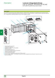
Presentation<br />
Lexium integrated drives<br />
ILp2 for <strong>DeviceNet</strong>, <strong>EtherCAT</strong>, <strong>Modbus</strong> <strong>TCP</strong>,<br />
<strong>Ethernet</strong> <strong>Powerlink</strong><br />
1<br />
2<br />
3<br />
4<br />
5<br />
6<br />
7<br />
8<br />
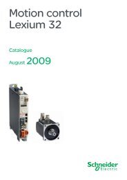
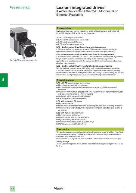
ILA2 with AC synchronous servo motor<br />
Presentation<br />
ILp2 comprise motor, control electronics and a fieldbus interface for <strong>DeviceNet</strong>,<br />
<strong>EtherCAT</strong>, <strong>Modbus</strong> <strong>TCP</strong> and <strong>Ethernet</strong> <strong>Powerlink</strong>.<br />
The ILp2 product group includes:<br />
b ILA2 with AC synchronous servo motor<br />
b ILE2 with brushless DC motor<br />
b ILS2 with 3-phase stepper motor<br />
ILA2 – the Integrated Drive System for dynamic processes<br />
ILA2 has an AC synchronous servo motor. This motor is characterised by high<br />
dynamics with the possibility of short-term overcurrent during acceleration.<br />
ILE2 – the Integrated Drive System for automatic format adjustment<br />
ILE2 is fitted with a brushless DC motor. The brushless DC motors have high detent<br />
torque at zero current. This makes a holding brake unnecessary in most<br />
applications. In combination with the electronics ILE2 has the characteristics of an<br />
absolute value encoder.<br />
ILS2 – the Integrated Drive System for short-distance positioning<br />
With its 3-phase stepper motor, ILS2 offers high torque at low speeds of rotation.<br />
ILS2 are ideally suited as drives in velocity mode with excellent constant velocity<br />
characteristics and also or for high-resolution positioning Commissioning the stepper<br />
motor drives is simple because it is not necessary to adjust the control loop.<br />
Special features<br />
ILA2 with AC synchronous servo motor<br />
b High dynamics and high peak torque<br />
b High-resolution singleturn encoder with a resolution of 16384 increments/<br />
revolution<br />
b Optionally with multiturn encoder with a resolution of 16384 increments/revolution<br />
with a positioning range of 4096 revolutions<br />
b Optionally with integrated holding brake<br />
b Planetary gear available as options<br />
ILE2 with brushless DC motor<br />
b High detent torque<br />
b Quasi-absolute encoder, therefore, no homing required after switching off and on<br />
b Optionally available with spur wheel gear or worm gear; planetary gear available<br />
as options<br />
ILS2 with 3-phase stepper motor<br />
b High continuous stall torque<br />
b Good constant velocity characteristics<br />
b High positioning resolution (0.018°)<br />
b Optionally with holding brake (ILS2p85 only)<br />
b Planetary gear available as options<br />
Electronics<br />
The electronic system comprises control electronics and power amplifier. They have<br />
a common power supply. The Lexium integrated drives can be parameterised and<br />
controlled via the fieldbus interface.<br />
Four different 24 V signals are also available. They can be used as input or output.<br />
Supply voltage<br />
These Lexium integrated drives can be operated with a supply voltage from 24 V up<br />
to 48 V.<br />
9<br />
10<br />
4/38
Presentation (continued)<br />
Lexium integrated drives<br />
ILp2 for <strong>DeviceNet</strong>, <strong>EtherCAT</strong>, <strong>Modbus</strong> <strong>TCP</strong>,<br />
<strong>Ethernet</strong> <strong>Powerlink</strong><br />
Connection technologies<br />
ILp2 have the following connections:<br />
b Supply voltage c V<br />
b Fieldbus interface: <strong>DeviceNet</strong>, <strong>EtherCAT</strong>, <strong>Ethernet</strong> <strong>Powerlink</strong>, <strong>Modbus</strong> <strong>TCP</strong>/IP<br />
b RS 485 commissioning interface<br />
b 24 V signal interface for four inputs/outputs<br />
b Signal interface for “Safe Torque Off” safety function (“Power Removal”)<br />
Fieldbus interface<br />
The following fieldbuses can be connected to the fieldbus interface depending on the<br />
device version:<br />
b<br />
b<br />
b<br />
<strong>DeviceNet</strong> (<strong>DeviceNet</strong> Standard)<br />
<strong>EtherCAT</strong> (as per IEEE 802.3 standard)<br />
<strong>Ethernet</strong> <strong>Powerlink</strong> (as per IEEE 802.3 standard)<br />
<strong>Modbus</strong> <strong>TCP</strong> (as per IEEE 802.3 standard)<br />
b<br />
The fieldbus interface is used to parameterise and control the Integrated Drive<br />
System.<br />
ILp2 with <strong>DeviceNet</strong> interface support the ADR function (Automatic Device<br />
Replacement). This function enables easy replacement of drive systems with<br />
automatic parameterisation.<br />
In addition, the Integrated Drive System can be commissioned with a PC connected<br />
to the fieldbus interface and the PC commissioning software. This requires an<br />
appropriate fieldbus converter.<br />
RS 485 commissioning interface<br />
An RS 485 commissioning interface is available in addition to the fieldbus interface.<br />
The RS 485 commissioning interface is also used for commissioning the drive<br />
system.<br />
The drive system can also be monitored during operation with the RS 485<br />
commissioning interface and the “Lexium CT” commissioning software.<br />
Simultaneous fieldbus and RS 485 connections are possible.<br />
24 V signal interface<br />
Four 24 V signals are available, which can be used either as an input or an output.<br />
The 24 V signals are available to the master controller via the fieldbus. They can<br />
also be used for predefined functions, such as for connection of limit switches and<br />
reference switches.<br />
The 24 V power supply to the signal outputs is internal via the supply voltage of the<br />
Integrated Drive System.<br />
Signal interface for “Safe Torque Off” safety function (“Power Removal”)<br />
The integrated “Safe Torque Off” safety function (“Power Removal”) enables a stop<br />
of category 0 or 1 as per IEC/EN 60204-1 without external power contactors. The<br />
supply voltage does not have to be interrupted. This reduces the system costs and<br />
response times.<br />
The safety function is activated via two redundant 24 V input signals (low active).<br />
1<br />
2<br />
3<br />
4<br />
5<br />
6<br />
7<br />
8<br />
9<br />
10<br />
4/39
Presentation (continued)<br />
Lexium integrated drives<br />
ILp2 for <strong>DeviceNet</strong>, <strong>EtherCAT</strong>, <strong>Modbus</strong> <strong>TCP</strong>,<br />
<strong>Ethernet</strong> <strong>Powerlink</strong><br />
1<br />
2<br />
3<br />
Integrated drive system with<br />
printed circuit board connectors<br />
Connection technologies (continued)<br />
Printed circuit board connector<br />
Printed circuit board plug connectors are preferably used for cabling series<br />
machines with cable harnesses.<br />
b<br />
Fieldbus and I/O signal connection with connector “Molex Micro Fit"<br />
Power supply connection with “AMP Positive Lock” crimp contacts<br />
b<br />
Two cable entries are required for cabling the Lexium integrated drives (see<br />
accessories, page 4/107).<br />
7 1<br />
8 2<br />
9 3<br />
10 4<br />
11 5<br />
VDC<br />
CN1<br />
1 2 3<br />
0VDC<br />
CN6<br />
1 2 3<br />
CN5<br />
1<br />
2<br />
4<br />
12 6<br />
CN2<br />
4 5 6<br />
CN3<br />
4 5 6<br />
CN4<br />
Printed circuit board connector, overview of connections<br />
5<br />
6<br />
Connection<br />
CN1<br />
CN2<br />
CN3<br />
CN4<br />
CN5<br />
CN6<br />
Assignment<br />
Supply voltage c V<br />
Fieldbus interface<br />
RS 485 commissioning interface<br />
24 V signal interface<br />
Interface for “Safe Torque Off” safety function (“Power Removal”)<br />
Jumper for disabling “Safe Torque Off” safety function (“Power<br />
Removal”)<br />
7<br />
Industrial connectors (optional)<br />
Lexium integrated drives with industrial connectors are preferably used in special<br />
machines and small series.<br />
The device version with industrial connectors has a connector housing with M12<br />
circular connectors (5 poles) for the fieldbus connection and a Hirschmann STASEI<br />
200 connector for connection of the power supply.<br />
8<br />
9<br />
10<br />
Integrated drive system with<br />
industrial connectors<br />
VDC<br />
+ –<br />
OUT IN<br />
Industrial connector, overview of connections<br />
Note:<br />
b <strong>DeviceNet</strong> and <strong>Modbus</strong> <strong>TCP</strong>: 1 circular connector for IN and OUT signals<br />
b <strong>EtherCAT</strong> and <strong>Ethernet</strong> <strong>Powerlink</strong>: 2 circular connectors (1 circular connector each for IN and<br />
OUT signals)<br />
4/40
Presentation (continued)<br />
Lexium integrated drives<br />
ILp2 for <strong>DeviceNet</strong>, <strong>EtherCAT</strong>, <strong>Modbus</strong> <strong>TCP</strong>,<br />
<strong>Ethernet</strong> <strong>Powerlink</strong><br />
Connection technologies (continued)<br />
I/O signal inserts<br />
One or two I/O signal inserts with industrial connectors can be ordered for connection of the I/O signals (see accessories, pages 4/109 and<br />
4/110).<br />
The 24 V power supply to the signal outputs is internal. Different I/O signal inserts are available for this purpose.<br />
1<br />
I/O signal inserts without “Safe Torque Off” safety function (“Power Removal”)<br />
IO1 IO0 IO3<br />
2<br />
4<br />
3 1<br />
4<br />
3 1<br />
4<br />
3 1<br />
Inserts for three I/O signals<br />
3<br />
I/O signal inserts with “Safe Torque Off” safety function (“Power Removal”)<br />
IO1<br />
IO0<br />
4<br />
3 1<br />
4<br />
3 1<br />
2 4<br />
1 3<br />
STO_A<br />
STO_B<br />
4<br />
Insert for two I/O signals and STO signals for safety function<br />
STO_B<br />
STO_A<br />
STO_A<br />
STO _B<br />
5<br />
IO1 IO0 IO3 IO2<br />
4<br />
3 1<br />
4<br />
3 1<br />
2 4<br />
1 3<br />
2 4<br />
1 3<br />
4<br />
3 1<br />
4<br />
3 1<br />
6<br />
Inserts for four I/O signals and STO signals for safety function<br />
Connection example I/O signal<br />
~ +<br />
-<br />
Vc<br />
Vc<br />
0Vc<br />
ILp<br />
CN4.6<br />
+<br />
-<br />
LIMN<br />
7<br />
UBC<br />
+<br />
8<br />
CN4.3<br />
-<br />
LIMP<br />
CN4.1<br />
CN4.4<br />
CN4.5<br />
+<br />
-<br />
REF<br />
9<br />
STO_A<br />
STO_B<br />
CN5.1<br />
CN5.2<br />
CN4.2<br />
Connection example with four I/O signals<br />
10<br />
4/41
Functions<br />
Lexium integrated drives<br />
ILp2 for <strong>DeviceNet</strong>, <strong>EtherCAT</strong>, <strong>Modbus</strong> <strong>TCP</strong>,<br />
<strong>Ethernet</strong> <strong>Powerlink</strong><br />
1<br />
2<br />
3<br />
4<br />
Configuration via parameter switches<br />
The following settings can be made at the Integrated Drive System via parameter<br />
switches:<br />
b<br />
v<br />
b<br />
v<br />
<strong>Ethernet</strong><br />
Setting IP address<br />
<strong>DeviceNet</strong><br />
Setting fieldbus address<br />
Operating modes<br />
Overview<br />
The following operating modes can be set via the fieldbus:<br />
b Electronic gear (only ILA2 with singleturn encoder)<br />
b Profile velocity<br />
b Jog<br />
b Profile position<br />
b Homing<br />
Electronic gear (only ILA2 with singleturn encoder)<br />
In “Electronic Gear” operating mode with singleturn encoder, the reference signals<br />
are supplied from an encoder (A/B signals) or a controller (pulse/direction signals)<br />
and a new position reference value is calculated using an adjustable gear ratio.<br />
Reference value setting<br />
The reference value are supplied as pulse/direction or A/B encoder signals.<br />
Application example<br />
Synchronisation of motion sequences, e.g. cutting material on a conveyor belt.<br />
5<br />
6<br />
NC:<br />
200 Inc<br />
Z 1<br />
N = 1<br />
Z 3<br />
N = 2<br />
Z 3<br />
N = 1<br />
1st drive system:<br />
200 Inc<br />
2nd drive system:<br />
300 Inc<br />
3rd drive system:<br />
600 Inc<br />
"Electronic Gear” operating mode<br />
7<br />
8<br />
9<br />
10<br />
4/42
Functions (continued)<br />
Lexium integrated drives<br />
ILp2 for <strong>DeviceNet</strong>, <strong>EtherCAT</strong>, <strong>Modbus</strong> <strong>TCP</strong>,<br />
<strong>Ethernet</strong> <strong>Powerlink</strong><br />
Profile velocity<br />
In operating mode “Profile velocity", a reference speed for the motor is set and a<br />
movement without a target position is started. This speed is maintained until a<br />
different reference speed is specified or the operating mode is changed.<br />
Reference value setting<br />
The reference value is set via fieldbus or PC.<br />
Application example<br />
Application of paint in CD manufacture<br />
v<br />
1<br />
2<br />
v 2<br />
v 3<br />
t 8<br />
t 9<br />
v 1<br />
0<br />
t 1<br />
t 2<br />
t 3<br />
t 4<br />
t 5<br />
t 6<br />
t 7<br />
Start<br />
Profile velocity<br />
Stop<br />
t<br />
3<br />
t 1<br />
, t 3<br />
, t 5<br />
= acceleration<br />
t 2<br />
, t 4<br />
, t 6<br />
, t 8<br />
= constant movement<br />
t 7<br />
, t 9<br />
= braking<br />
Jog mode<br />
The motor moves by one distance unit or at constant speed in continuous operation.<br />
The value of the distance unit, the speed levels and the change-over time in<br />
continuous operation can be adjusted manually.<br />
Reference value setting<br />
The reference value is set via fieldbus or PC.<br />
Application example<br />
Setting up a machine during commissioning<br />
4<br />
5<br />
Parameter<br />
startMan, Bit0<br />
Parameter<br />
startMan, Bit2<br />
1<br />
0<br />
1<br />
0<br />
n_fastMan<br />
6<br />
Motor<br />
Parameter<br />
stateMan, Bit14<br />
M<br />
Stop<br />
Jog, slow and fast<br />
1<br />
2<br />
3<br />
4<br />
step_Man<br />
t < time_Man<br />
time_Man<br />
Continuous operation<br />
1<br />
0<br />
n_slowMan<br />
1 2 1 3 4<br />
7<br />
8<br />
9<br />
10<br />
4/43
Functions (continued)<br />
Lexium integrated drives<br />
ILp2 for <strong>DeviceNet</strong>, <strong>EtherCAT</strong>, <strong>Modbus</strong> <strong>TCP</strong>,<br />
<strong>Ethernet</strong> <strong>Powerlink</strong><br />
1<br />
2<br />
Profile position<br />
In the operating mode “Profile Position", the motor is positioned from a point A to a<br />
point B with a positioning command.<br />
Settings<br />
The positioning path can be specified in two ways:<br />
b Absolute positioning, reference point is the zero point of the axis<br />
b Relative positioning, reference point is the current position of the motor<br />
Reference value setting<br />
The reference value is set via fieldbus or PC.<br />
Application example<br />
Pick-and-place with a linear robot<br />
3<br />
0<br />
500 Inc<br />
1.200 Inc<br />
0<br />
500 Inc<br />
700 Inc<br />
Operating mode “Profile Position", absolute and relative<br />
4<br />
5<br />
6<br />
7<br />
Homing<br />
There are two types of the “Homing” operating mode:<br />
b Reference movement<br />
Specifying the dimension reference by approach to a limit or reference switch<br />
b Position setting<br />
Specifying the position reference relative to the current motor position<br />
Note: In the case of ILA2 with multiturn encoder, a valid actual motor position is available<br />
immediately after starting. Therefore, homing to external limit switches is not required.<br />
Reference movement<br />
During reference movement, the motor moves to a defined position on the axis. The<br />
position is defined by a mechanical switch:<br />
b<br />
b<br />
LIMN, LIMP limit switches<br />
REF reference switch<br />
Types of reference movements<br />
There are six standard reference movements:<br />
b Movement to negative limit switch LIMN<br />
b Movement to positive limit switch LIMP<br />
b Movement to REF reference switch with first movement counterclockwise<br />
b Movement to REF reference switch with first movement clockwise<br />
b Reference movement to index pulse with clockwise or counterclockwise rotation<br />
(not with ILE2)<br />
b Reference movement to block = mechanical stop (ILE2 only)<br />
8<br />
9<br />
10<br />
4/44
Functions (continued)<br />
Lexium integrated drives<br />
ILp2 for <strong>DeviceNet</strong>, <strong>EtherCAT</strong>, <strong>Modbus</strong> <strong>TCP</strong>,<br />
<strong>Ethernet</strong> <strong>Powerlink</strong><br />
Example 1: reference movement to limit switch<br />
LIMN<br />
LIMP<br />
1<br />
1<br />
M<br />
2<br />
2<br />
3<br />
R-<br />
3<br />
p_disHome<br />
p_outHome<br />
v_Home<br />
v_outHome<br />
Operating mode “Homing", reference movement to limit switch<br />
1<br />
2<br />
3<br />
Movement to limit switch at search speed<br />
Movement to switching edge at clearance speed<br />
Movement to distance from switching edge at clearance speed<br />
Example 2: position setting<br />
Position setting can be used to execute a continuous motor movement without<br />
overtravelling the positioning limits.<br />
4<br />
5<br />
M<br />
M<br />
M<br />
0<br />
1<br />
2<br />
"2000"<br />
"0"<br />
0<br />
2000 Inc<br />
3<br />
2000 Inc<br />
6<br />
Positioning by 4000 increments with position setting<br />
1<br />
2<br />
3<br />
The motor is positioned 2000 increments.<br />
The current motor position is set to position value 0 by position setting to 0 and<br />
the new zero point is defined at the same time.<br />
The new target position is 2000 increments after triggering a new travel command<br />
by 2000 increments.<br />
This procedure prevents overtravel of the absolute position limits during positioning,<br />
because the zero point is continuously made to follow.<br />
Reference value setting<br />
The reference value is set via fieldbus or PC.<br />
Application example<br />
Prior to absolute positioning in “Profile Position” mode.<br />
Additional operating modes<br />
Additional operating modes can be activated via fieldbus or PC:<br />
b Brake function<br />
b Reversing direction of rotation of motor<br />
b Setting motion profile via profile generator<br />
b Setting motor phase current<br />
b Triggering “Quick Stop” function<br />
b Fast position capture via signal input (Capture)<br />
b Programming signal inputs/outputs.<br />
b Translation of user-defined units (scaling)<br />
b Monitoring functions<br />
7<br />
8<br />
9<br />
10<br />
4/45
Functions (continued)<br />
Lexium integrated drives<br />
ILp2 for <strong>DeviceNet</strong>, <strong>EtherCAT</strong>, <strong>Modbus</strong> <strong>TCP</strong>,<br />
<strong>Ethernet</strong> <strong>Powerlink</strong><br />
1<br />
2<br />
3<br />
4<br />
5<br />
"Safe Torque Off” (“Power Removal”) safety function<br />
The Lexium integrated drive integrates the “Safe Torque Off” (“Power Removal”)<br />
safety function which prevents unintended restarting of the motor. The motor no<br />
longer produces any torque if the safety function is active.<br />
This safety function:<br />
b Complies with the machine safety standard ISO 13849-1, perfomance level “d”<br />
(PL d) .<br />
b Complies with the standard for functional safety IEC/EN 61508, SIL2 capability<br />
(safety control-signalling applied to processes and systems). The SIL (Safety<br />
Integrity Level) capability depends on the connection diagram for the servo drive<br />
and for the safety function. Failure to observe the setup recommendations could<br />
inhibit the SIL capability of the “Safe Torque Off” (“Power Removal”) safety<br />
function.<br />
b Complies with product standard IEC/EN 61800-5-2 “Adjustable speed electrical<br />
power drive systems – Part 5-2: Safety requirements – Functional” for both stop<br />
functions:<br />
v Safe Torque Off (“STO”) corresponds to Category 0 stop according to<br />
IEC/EN 60204-1. Standstill by immediate power shutdown to the machine drive<br />
elements (i.e. an uncontrolled stop).<br />
v Safe Stop 1 (“SS1”) corresponds to Category 1 stop according to<br />
IEC/EN 60204-1. A controlled stop in which the machine drive elements are<br />
retained to effect the standstill. The final shutdown is ensured by an external<br />
Emergency stop module with safe time delay, e.g. Preventa XPS-AV (1).<br />
The “Safe Torque Off” (“Power Removal”) safety function has a redundant electronic<br />
architecture (2) which is monitored continuously by a diagnostics function.<br />
This PL d and SIL2 safety function is certified as conforming to these standards by<br />
the TÜV certification body in the context of a voluntary certification.<br />
(1) Please refer to the “Safety functions and solutions using Preventa” catalogue.<br />
(2) Redundant: Consists of mitigating the effects of the failure of one component by means of the<br />
correct operation of another, assuming that faults do not occur simultaneously on both.<br />
6<br />
7<br />
8<br />
9<br />
10<br />
4/46
Functions (continued)<br />
Lexium integrated drives<br />
ILp2 for <strong>DeviceNet</strong>, <strong>EtherCAT</strong>, <strong>Modbus</strong> <strong>TCP</strong>,<br />
<strong>Ethernet</strong> <strong>Powerlink</strong><br />
Examples of applications of the safety function<br />
24V<br />
Emergency<br />
stop<br />
24V<br />
ENABLE<br />
FAULT RESET<br />
PLC/CNC<br />
ILp<br />
1<br />
STO_A<br />
STO _B<br />
2<br />
Example of Category 0 Stop<br />
3<br />
24V<br />
24V 24V 24V<br />
24V<br />
Emergency<br />
stop<br />
Y+<br />
Example of Category 1 Stop<br />
Preventa<br />
XPS-AV<br />
Y64<br />
Y74<br />
Y84<br />
delayed<br />
37<br />
38<br />
47<br />
48<br />
57<br />
not<br />
58<br />
delayed<br />
03 04<br />
13<br />
14<br />
23<br />
24<br />
S31<br />
S11<br />
S21<br />
S12<br />
S22<br />
S13<br />
S32<br />
S14<br />
A1<br />
A2<br />
ENABLE<br />
FAULT RESET<br />
PLC/CNC<br />
ILp<br />
STO_A<br />
STO_B<br />
4<br />
5<br />
6<br />
7<br />
8<br />
9<br />
10<br />
4/47