Dynapar Catalog
Dynapar Catalog
Dynapar Catalog

You also want an ePaper? Increase the reach of your titles
YUMPU automatically turns print PDFs into web optimized ePapers that Google loves.
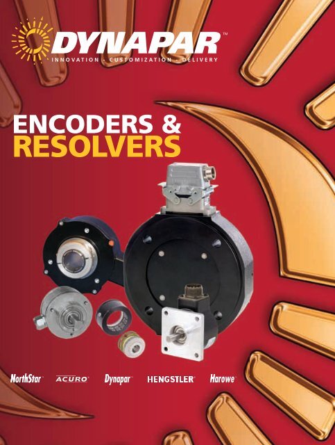
ENCODERs &<br />
REsOlvERs
Innovation, Customization, Fast Delivery, and the<br />
most comprehensive encoder selection in the<br />
industry…<strong>Dynapar</strong> delivers the rotary feedback<br />
solutions customers are demanding.<br />
<strong>Dynapar</strong> is an ISO 9000 certified facility and has been manufacturing encoders in Gurnee Ilinois<br />
since 1955. Today <strong>Dynapar</strong> offers the widest selection of the industry’s most trusted brands in motion<br />
feedback control, including NorthStar heavy duty optical and harsh duty magneto resistive encoders, Acuro<br />
absolute encoders, <strong>Dynapar</strong> incremental encoders, Hengstler Euro-spec models, and Harowe resolvers.<br />
These brands serve the spectrum of heavy, industrial, servo, and light-duty applications.<br />
Innovation is engrained into the fabric of our company. At <strong>Dynapar</strong>, we pride ourselves on being at the<br />
forefront of feedback technology, making advances to our products through a detailed understanding of the<br />
voice of our customers. <strong>Dynapar</strong> pioneered the first true vector-duty hollow-shaft encoder building on<br />
our strong presence in a number of industries including steel, paper, medical, material handling and<br />
industrial motor manufacturing.<br />
Customization capability allows customers to meet the varied specifications of feedback application.<br />
Shafts, tethers, cables, connectors, and housings can be modified by local engineering teams, and<br />
quickly put into production to give our customers the right-fit product.<br />
Fast Delivery is a customer requirement, and at <strong>Dynapar</strong> we take pride in operational excellence. All<br />
<strong>Dynapar</strong> and NorthStar encoders are built to order utilizing a Just-In-Time (JIT) manufacturing process,<br />
allowing for fast Delivery and 3 day lead times on most models.<br />
Depend on <strong>Dynapar</strong>…..Innovation—Customization—Delivery
New Products<br />
New products<br />
dyNapar 2010<br />
m53 page 3.26 hs35r page 2.44<br />
Key Features:<br />
• Redesigned circuitry for higher<br />
reliability<br />
• Compact size for small motors<br />
• Modular design w/integral gapping<br />
Key Features:<br />
• New Phased Array Technology<br />
• High Resolution with unbreakable<br />
discs<br />
• Wide sensor gap for high shock<br />
loading<br />
hc20 page 3.38 hs60 page 1.60<br />
Key Features:<br />
• Phased array technology<br />
• Wide 0 to 120ºC operating<br />
temperature<br />
• Cost-effective high performance<br />
Key Features:<br />
• Improved Seals<br />
• Large 2-7/8” bore capability<br />
• Anodized endbells for shaft<br />
isolation<br />
• Stainless clamping shaft hub<br />
ad34 page 3.04 ar62 page 1.64<br />
Key Features:<br />
• Up to 17 bit absolute positioning<br />
• 10,000 RPM capability for servo<br />
feedback<br />
• Special shaft for easy one-step<br />
mounting<br />
• Available with hubshaft (AD35)<br />
Key Features:<br />
• Magnetic Technology<br />
• 12 bit true absolute positioning<br />
• Oversized bearings for high<br />
shaft loads<br />
• Submersible<br />
hsd44 page 1.26 Northstar hd optical sectioN 1<br />
Key Features:<br />
• O-ring housing with pilot seals<br />
against motor for the ultimate in<br />
protection<br />
• Isolated coupling compensates for<br />
motor shaft runout and endplay<br />
• Perfect for off-highway vehicle applications<br />
with high shock and vibration<br />
• Unbreakable code disc<br />
Key Features:<br />
• Unbreakable discs<br />
• High temperature capability<br />
• Phased Array Sensor<br />
Technology<br />
• Intrinsic Safety on select<br />
models<br />
A.01
TABLE OF CONTENTS<br />
by<br />
Refer to page number A.12 for Selection Guide<br />
providing encoder choice by application and<br />
operating characteristics.<br />
Section A. Encoder Introduction<br />
<strong>Dynapar</strong> & NorthStar New Products A.01<br />
<strong>Catalog</strong> Table of Contents A.02<br />
Reference Encoder Technology Overview A.04<br />
Reference Encoder Mounting Configurations A.08<br />
Reference Encoder Duty Classification A.10<br />
Encoder Selection Guide A.12<br />
Section 1. Heavy Duty Encoders<br />
Heavy Duty Encoder Introduction 1.00<br />
Heavy Duty Encoder Selection Guide 1.02<br />
HD20 NorthStar brand, Harsh Duty Optical Encoder 1.04<br />
HD25 NorthStar brand, Harsh Duty Optical Encoder 1.06<br />
HSD25 NorthStar brand, Harsh Duty Optical Encoder 1.08<br />
HSD35 NorthStar brand, Heavy Duty Optical Encoder 1.12<br />
HSD37 NorthStar brand, Harsh Duty Optical Encoder 1.16<br />
HSD38 NorthStar brand, Harsh Duty Optical Encoder 1.20<br />
DWD38 NorthStar brand, Harsh Duty Optical Encoder 1.24<br />
HSD44 NorthStar brand, Extreme Heavy Duty Encoder 1.26<br />
EN42 NorthStar brand, Zone 1 Heavy Duty Encoder 1.28<br />
EN44 NorthStar brand, Extreme Heavy Duty Encoder 1.30<br />
H56 <strong>Dynapar</strong> brand, Heavy Duty Encoder 1.32<br />
X25 <strong>Dynapar</strong> brand, For Hazardous Location Application 1.34<br />
60 Rotopulser © <strong>Dynapar</strong> brand, Heavy Duty Rotopulser © 1.36<br />
60P Rotopulser © <strong>Dynapar</strong> brand, Heavy Duty Rotopulser © 1.38<br />
R45 Rotopulser © <strong>Dynapar</strong> brand, Bearingless Ring Kit 1.40<br />
SLIM Tach ® SL56 NorthStar brand, Bearingless Encoder 1.42<br />
SLIM Tach ® RL67 NorthStar brand, Bearingless Encoder 1.44<br />
SLIM Tach ® SL85 NorthStar brand, Bearingless Encoder 1.46<br />
SLIM Tach ® SL1250 NorthStar brand, Bearingless Encoder 1.50<br />
RIM Tach ® 8500 NorthStar brand, Bearingless Encoder 1.52<br />
RIM Tach ® 1250 NorthStar brand, Bearingless Encoder 1.54<br />
RIM Tach ® 6200 NorthStar brand, Severe Duty Encoder 1.56<br />
SLIM Tach ® HS56 NorthStar brand, Hollow Shaft Encoder 1.58<br />
SLIM Tach ® HS60 NorthStar brand, Hollow Shaft Encoder 1.60<br />
RIM Tach ® HS85 NorthStar brand, Hollow Shaft Encoder 1.62<br />
AR62/AR63 ACURO brand, Magnetic Absolute Encoder 1.64<br />
AX70/AX71 ACURO brand, Magnetic Absolute Encoder 1.66<br />
R25 Harowe brand, Heavy Duty Resolver 1.70<br />
A.02<br />
Section 2. Industrial Duty Encoders<br />
Industrial Duty Encoder Introduction 2.00<br />
Industrial Duty Encoder Selection Guide 2.02<br />
22 <strong>Dynapar</strong> brand, “QUBE” Encoder 2.04<br />
H20 <strong>Dynapar</strong> brand, Shafted Encoder 2.08<br />
HA25 <strong>Dynapar</strong> brand, Shafted Encoder 2.12<br />
HR25 <strong>Dynapar</strong> brand, Shafted Encoder 2.16<br />
HC25 <strong>Dynapar</strong> brand, Shafted Encoder 2.20<br />
H58 <strong>Dynapar</strong> brand, Shafted Encoder 2.24<br />
H42 <strong>Dynapar</strong> brand, Shafted Encoder 2.28<br />
HA725 <strong>Dynapar</strong> brand, Shafted Encoder 2.30<br />
H20 Hubshaft <strong>Dynapar</strong> brand, Shafted Encoder (Hubshaft) 2.32<br />
HS20 <strong>Dynapar</strong> brand, Sealed Hollowshaft Encoder 2.36<br />
HS35 <strong>Dynapar</strong> brand, Sealed Hollowshaft Encoder 2.40<br />
HS35R <strong>Dynapar</strong> brand, Sealed Hollowshaft Encoder 2.44<br />
RI80E Hengstler brand, Hollowshaft Encoder 2,48<br />
HA26 <strong>Dynapar</strong> brand, Integral Coupling Encoder 2.50<br />
HR26 <strong>Dynapar</strong> brand, Integral Coupling Encoder 2.54<br />
HC26 <strong>Dynapar</strong> brand, Integral Coupling Encoder 2.58<br />
AC36 ACURO brand, Absolute Encoder 2.62<br />
AI25 DeviceNet ACURO brand, Absolute Encoder 2.64<br />
AI25 CAN Open ACURO brand, Absolute Encoder 2.66<br />
AI25 CAN Layer 2 ACURO brand, Absolute Encoder 2.68<br />
AI25 Profibus ACURO brand, Absolute Encoder 2.70<br />
AI25 Interbus ACURO brand, Absolute Encoder 2.72<br />
AI25 BISS ACURO brand, Absolute Encoder 2.74<br />
AI25 SSI ACURO brand, Absolute Encoder 2.76<br />
AI25 Parallel ACURO brand, Absolute Encoder 2.80<br />
AC110 ACURO brand, Absolute Encoder 2.84
y<br />
TABLE OF CONTENTS<br />
Refer to page number A.12 for Selection Guide<br />
providing encoder choice by application and<br />
operating characteristics.<br />
Section 3. Servo Duty Encoders<br />
Servo Duty Encoder Introduction 3.00<br />
Servo Duty Encoder Selection Guide 3.02<br />
AD34 ACURO brand, Single Turn Absolute Encoder 3.04<br />
AD35 ACURO brand, Single Turn Absolute Encoder 3.06<br />
AD36 ACURO brand, Single- / Multi- Turn Absolute Encoder 3.08<br />
AD25 ACURO brand, Single- / Multi- Turn Absolute Encoder 3.10<br />
M602 & M832 <strong>Dynapar</strong> brand, Kit Encoder 3.12<br />
LM & LAM <strong>Dynapar</strong> brand, Kit Encoder 3.15<br />
E9 <strong>Dynapar</strong> brand, Miniature Encoder 3.18<br />
M9 <strong>Dynapar</strong> brand, Miniature Encoder 3.20<br />
M14 <strong>Dynapar</strong> brand, Miniature Encoder 3.22<br />
M15 <strong>Dynapar</strong> brand, For Stepper & Small Servo Motors 3.24<br />
M53 <strong>Dynapar</strong> brand, For Stepper & Small Servo Motors 3.26<br />
F10 <strong>Dynapar</strong> brand, For Stepper & Small Servo Motors 3.28<br />
F14 <strong>Dynapar</strong> brand, For Stepper & Small Servo Motors 3.30<br />
F15 <strong>Dynapar</strong> brand, For Stepper & Small Servo Motors 3.32<br />
F18 <strong>Dynapar</strong> brand, For Stepper & Small Servo Motors 3.34<br />
F21 <strong>Dynapar</strong> brand, For Stepper & Small Servo Motors 3.36<br />
HC20 <strong>Dynapar</strong> brand, For Stepper & Small Servo Motors 3.38<br />
11 / R11 Harowe brand, Heavy Duty Brushless Resolvers 3.40<br />
Frameless Resolvers Harowe brand, Heavy Duty Brushless Resolvers 3.41<br />
HaroMax Series 15 Harowe brand, Heavy Duty Brushless Resolvers 3.42<br />
HaroMax Series 21 Harowe brand, Heavy Duty Brushless Resolvers 3.43<br />
Section 4. Light Duty Encoders<br />
Light Duty Encoder Introduction 4.00<br />
Light Duty Encoder Selection Guide 4.01<br />
E12 <strong>Dynapar</strong> brand, Miniature Encoder 4.02<br />
E14 <strong>Dynapar</strong> brand, Miniature Encoder 4.04<br />
E23 <strong>Dynapar</strong> brand, Miniature Encoder 4.06<br />
EC23 <strong>Dynapar</strong> brand, Miniature Encoder 4.08<br />
E14H <strong>Dynapar</strong> brand, Hubshaft Miniature Encoder 4.10<br />
E14IC <strong>Dynapar</strong> brand, Integral Coupling Miniature Encoder 4.12<br />
Section 4. Encoder Accessories<br />
Replacement Wheels NorthStar brand, Wheel Selection 5.00<br />
Sensor Modules NorthStar brand, Sensor Module Selection 5.01<br />
Connectors & Cables Cable Assemblies, Mating Connectors, Bulk Cable, Patch Cords 5.02<br />
CPL <strong>Dynapar</strong> brand, CPL Seies Couplings 5.03<br />
FV2 <strong>Dynapar</strong> brand, Brushless Digital Feedback 5.05<br />
FV3 <strong>Dynapar</strong> brand, Frequency to Voltage Converter 5.06<br />
Mounting Brackets <strong>Dynapar</strong> brand, “L” Mounting Bracket 5.07<br />
Pivot Mount <strong>Dynapar</strong> brand, Pivot Mounting Bracket 5.08<br />
Universal Mount <strong>Dynapar</strong> brand, Universal Mounting Bracket 5.09<br />
Qube Pivot Mount <strong>Dynapar</strong> brand, Pivot Mounting Bracket for Qube Encoder 5.10<br />
C-Face Adapter <strong>Dynapar</strong> brand, C-Face Adapter 5.11<br />
5PY Adapter <strong>Dynapar</strong> brand, 5PY Adapter for 2-1/2” Encoders 5.12<br />
5PY Adapter <strong>Dynapar</strong> brand, 5PY Adapter for X25 Encoders 5.13<br />
RIM M100 Tester NorthStar brand, RIM M100 Encoder Tester and Accessories 5.14<br />
RIM SS2 Splitter NorthStar brand, RIM SS2 Signal Splitter 5.15<br />
RIM SSW Switcher NorthStar brand, RIM SSW Signal Switcher 5.16<br />
<strong>Dynapar</strong>, NorthStar, ACURO, Harowe and HaroMax brands are trademarks of DYNAPAR.<br />
All rights reserved, DYNAPAR 2010<br />
A.03
Technology overview<br />
technology oveRvIew<br />
dynApAR 2010<br />
There are three main types of feedback devices:<br />
absolute, incremental, and resolver.<br />
90°<br />
90°<br />
0°<br />
Absolute encoders are typically used in CNC, medical, and<br />
robot applications where high resolution is required and absolute<br />
feedback reduces power up sequences.<br />
Incremental encoders can be used in positioning and motor<br />
speed feedback applications. These would specifically be cutto-length,<br />
crane or hoist, and heavy vehicle applications.<br />
180°<br />
180° 0°<br />
270°<br />
270°<br />
Good<br />
Bad<br />
Resolvers are used in applications that are environmentally<br />
demanding. This means extreme temperatures, shock, and<br />
vibration. These applications can be aerospace, military, heavy<br />
vehicle and radio active.<br />
Figure 1: Accuracy<br />
It is also important to note the distinction between resolution and<br />
accuracy. The illustration in Figure 1 shows that although there<br />
is the same number of transitions in a rotation, they can clearly<br />
be in the incorrect real position if the feedback device has poor<br />
accuracy. The application engineer must pay very close attention<br />
to the accuracy of high resolution devices; it can be misleading.<br />
Cover<br />
Absolute encodeR oveRvIew<br />
Absolute rotary encoders are devices that<br />
transmits a numerical representation of the<br />
angular position of a shaft. This number is<br />
coded in binary or Gray code. Each digit in<br />
binary or Gray code is referred to as a bit. Each<br />
digit also represents an exponent of two starting<br />
with zero from the left. Therefore, the third digit<br />
from the left would be 22. The amount of bits an encoder has is<br />
equivalent to the resolution of the encoder. For example, a 22 bit<br />
encoder has a resolution of approximately four million counts per<br />
revolution or 2 22 counts. Transmission of high resolution values<br />
such as this can take place through several interfaces such as<br />
BiSS, SSI, Profibus, DeviceNet, etc.<br />
Multi-turn PCB<br />
Spindle<br />
Multi-turn Gear Train<br />
Single-turn PCB<br />
Figure 2: SSI/BiSS Encoder Assembly<br />
Absolute encoders are made of these<br />
primary components.<br />
A.04
Technology overview<br />
The cover insures that the encoder is protected from the outside<br />
elements of the application. This could be washdown for the<br />
food industry, stainless for marine applications, or heavy duty for<br />
volatile environments.<br />
The Multi turn PCB and gear train keeps an accurate count<br />
of the amount times the shaft has made a full rotation. On the<br />
PCB, there are three opto asics cascaded and transmitting<br />
position down the line using the BiSS protocol. Each opto asic<br />
is reading a transparent gear that is coded with an absolute<br />
position. The last ASIC transmits a complete 12 bit turn count<br />
to the single turn PCB. It is important to note that this is done<br />
without the use of a battery, so the count will be valid for the life<br />
of the encoder.<br />
The single turn PCB has a single opto asic reading from a disk<br />
that is coded similar to the gears above it. The exception is that<br />
the disk has more tracks plus an incremental sinusoidal track<br />
that is used for a secondary output or for interpolating up to<br />
22 bits.<br />
The spindle primarily contains the bearing, flange, and shaft that<br />
meet the mechanical demands of the application. The spindle<br />
guarantees that the encoder will stand up to the specified shock<br />
and vibration, but proper assembly also insures that the encoder<br />
meets the specified accuracy.<br />
Absolute encoders are typically used in CNC, medical, and<br />
robot applications where high resolution is required and absolute<br />
feedback reduces power up sequences.<br />
Figure 3: Coded Gear<br />
Figure 4: Absolute Disk Section<br />
2048 cycles/360˚<br />
A-A*<br />
O° 360°/2048<br />
<br />
B-B*<br />
<br />
Figure 5: Incremental Sinusoidal Output<br />
A.05
Technology overview<br />
IncRementAl encodeR oveRvIew<br />
Incremental encoders provide a specified<br />
amount of pulses in one rotation of the encoder.<br />
The output can be a single line of pulses(an<br />
“A” channel) or two lines of pulses(an “A” and<br />
“B” channel) that are offset in order to determine<br />
rotation. This phasing between the two<br />
signals is called quadrature.<br />
The typical assembly of incremental encoders<br />
A-A*<br />
is reduced to a spindle assembly, PCB, and<br />
cover. Each component bears a similar purpose as the in the absolute<br />
encoders with the exception that the PCB contains a sensor array<br />
that creates just two primary signals for the purpose of position and<br />
B-B*<br />
speed.<br />
Optionally, additional signals can be provided:<br />
An index or ‘Z’ channel can be provided as one pulse per revolution<br />
signal for homing and pulse count verification on the A and/or B channels.<br />
This index can be gated to either A or B in their various states. It<br />
can also be un-gated and vary in width.<br />
Commutation(U,V,W) channels can also be provided on some encoders.<br />
These signals are aligned to the commutation windings found on<br />
servo motors. They also ensure that the drive or amplifier for those<br />
motors apply current to each winding in the correct sequence and at<br />
the correct level.<br />
ResolveR oveRvIew<br />
A resolver functions as an electro-mechanical<br />
position transducer which is essentially a variablecoupling<br />
or rotary transformer.<br />
Like all transformers, the resolver requires an AC<br />
carrier or reference signal (input excitation) to be<br />
applied to the primary winding, contained in the<br />
rotor. The resulting changing magnetic field in the<br />
primary winding induces a voltage in the secondary<br />
stator windings.<br />
The secondary of the resolver stator consists of<br />
two sets of windings that are at right angles to each other.<br />
The magnitude of the magnetic coupling between the primary and<br />
the secondary varies according to the position of the rotating element<br />
(rotor) which then varies the amplitude of the output voltage. The amplitude<br />
of the reference or input signal is modulated by the sine and<br />
the cosine of the rotor angle to produce the sine and cosine output<br />
signals on the two secondary windings as shown in Figure 7.<br />
Typically, there is one sine and one cosine wave per mechanical<br />
revolution which provides absolute position. A multi-speed resolver<br />
creates multiple sine and cosine waves throughout a revolution, which<br />
increases accuracy but at the expense of absolute position.<br />
A<br />
B<br />
Z<br />
Figure 6: Incremental O° Encoder Signal 360°/2048<br />
180°e<br />
CH. A<br />
90°e<br />
CH. B<br />
180°e<br />
CH. Z<br />
±1°m<br />
CCW Shaft Rotation<br />
180°e<br />
CH. U<br />
120°e<br />
CH. V<br />
120°e<br />
CH. W<br />
Figure 7: Commutation Channels<br />
Figure 7: Resolver Signal<br />
A.06
Technology overview<br />
encodeR engInes<br />
The engine in encoders is the<br />
internal technology used to provide<br />
the signal required by the customer.<br />
Engine in its more familiar use<br />
would be gas, hybrid, or electric.<br />
Engines in encoder technology<br />
would typically be optical with a<br />
mask, optical phased array, and<br />
magnetic.<br />
Traditional optical absolute and incremental encoders have four<br />
main components: LED, disk, mask, and sensor. The disk will<br />
have as many tracks as signals (A, B, Z, etc.), and the mask will<br />
have windows for each track. The windows on the mask will<br />
also have a size proportionate to the window size on the disk.<br />
In manufacturing, the mask is fastened directly to the sensor.<br />
This allows for one sensor to be used with several resolution<br />
options.<br />
Phased array technology essentially averages several signals to<br />
increases signal stability. Users can easily install these modules<br />
without the need of precision fixtures and align disks without the<br />
use of microscopes. Figure 8 shows the cross sectional side<br />
view of the disk, and how the components are used to provide<br />
a proper signal.<br />
This technology provides stable output during heavy shock and<br />
vibration, and opens up its use to oil rig, heavy vehicle, and<br />
military applications.<br />
Magnetic encoders consist of a magnetized wheel, magneto<br />
resistive sensors, and a signal conditioning electrical circuit.<br />
The wheel is magnetized mainly with 480, 512, and 600 pole<br />
pairs. The amount of sensors and the signal conditioning circuit<br />
logic combine to multiply or divide the number of pole pairs to<br />
result in several different resolution options using only the three<br />
different wheels.<br />
In absolute magnetic technology, there is a single pole pair<br />
rotating above a sensing element. The resolution is dependant<br />
upon the ability of the sensing element or ASIC (application<br />
specific integrated circuit)<br />
In both absolute and incremental magnetic encoders, the<br />
engine allows for use in applications that are equal to or more<br />
demanding than the phased array engine capabilities.<br />
Figure 8: Traditional Optical Encoder Engine<br />
CH. A<br />
CH. B<br />
CH. Z<br />
CH. U<br />
CH. V<br />
CH. W<br />
A<br />
Sensor<br />
A0<br />
B0<br />
A1<br />
An 120°e<br />
180°e<br />
90°e<br />
±1°m<br />
180°e<br />
120°e<br />
Sensor Array<br />
180°e<br />
Disk<br />
Mask<br />
CCW Shaft Rotation<br />
Figure 9: Phased Array Technology<br />
Electric Signal<br />
LED<br />
Disk<br />
LED<br />
Sensing Circuit<br />
(Thin Film,<br />
Non-Contacting<br />
Rotary Drum<br />
(Injection Molded<br />
Plastic)<br />
Multipoles<br />
(Permanently<br />
Magnetized)<br />
Figure 10: Incremental Magnetic Technology<br />
I<br />
M<br />
I<br />
U M<br />
A.07<br />
Figure 11: Absolute Magnetic Technology
EncodEr Mounting configurations<br />
hollow-shaft<br />
Encoders are applied to measure speed and position in a wide variety of applications<br />
and are therefore available with numerous mounting styles. The mounting style should<br />
be selected carefully to best fit the application at hand.<br />
The motor or machine shaft extends through the hollow encoder shaft and is affixed<br />
by a concentric clamp. A flexible tether or torque arm attaches to the motor or<br />
machine surface to prevent the encoder body from rotating with the shaft.<br />
concEnTric clamp<br />
NOTE: Eliminates the need for a coupling, and allows the encoder to be moved to<br />
the correct position for tethering without shaft modifications.<br />
Product Examples: HS35 (page 2.40), HS20 (page 2.36), AC110 (2.84)<br />
flExiblE TEThEr<br />
hub-shaft<br />
A hub shaft encoder is similar to the hollow-shaft configuration, except the shaft does<br />
not extend through the encoder.<br />
concEnTric clamp<br />
NOTE: Eliminates the need for a coupling, but may require a more precise shaft length<br />
to properly locate the encoder for tethering. This type provides improved sealing, as there is<br />
no opening on the back of the encoder.<br />
Product Examples: AI25 (2.64 - 2.80), HSD25 (page 1.08), E14 (page 4.04)<br />
flExiblE TEThEr<br />
shafted with coupling<br />
The original encoder configuration, a shafted encoder requires two special interfaces to<br />
properly mount the unit. The first is an encoder mount, which is typically either a mounting<br />
flange or a foot mount. The second is a flexible coupling, which compensates for<br />
shaft misalignment while providing little or no backlash.<br />
flangE mounT<br />
NOTE: This solution is typically used when a hollow or hub-shafted solution cannot<br />
work. It requires care in aligning the encoder and driven shafts.<br />
fooT mounT<br />
Product Examples: E14IC (page 4.12), HR26 (page 2.54)<br />
flExiblE coupling<br />
shafted with belt<br />
A shafted encoder can be interfaced to a driven shaft by a belt. This is often<br />
done when the driven shaft is too large for coupling, or the application is space<br />
constrained and the encoder must be located to the side.<br />
NOTE: The additional mechanical hardware adds cost and complexity to the system.<br />
Product Examples: H56 (page 1.32), RIM6200 (page 1.56)<br />
a.08
EncodEr Mounting configurations<br />
c-face<br />
NEMA motor come with standard interface dimensions on the face for mounting an<br />
aligning accessories. Common face mount dimensions are 4.5”, 8.5”, and 12.5”.<br />
C-face encoders mount the housing to the motor face, and mount a wheel to the<br />
motor shaft separately. These are bearing-less.<br />
NOTE: Bearing-less solution eliminates a wear component.<br />
Product Examples: SL56 (page 1.42), SL85 (page 1.46)<br />
gEar<br />
rEducEr<br />
moTor<br />
frameless resolver<br />
machinE<br />
Designed for standard resolver motor mounts, the resolver rotor mounts to the shaft,<br />
and the resolver housing mounts to the motor face. A clip secures the resolver housing<br />
via a groove, as shown.<br />
NOTE: A frameless resolver mount is a bearing-less solution that makes a rugged<br />
resolver technology even more rugged.<br />
Product Examples: HAROMAx 15 (page 3.42), HAROMAx 21 (page 3.43)<br />
sErvo groovE mounTing<br />
servo flex-mount<br />
This style of encoder mount is designed as a drop-in replacement for frameless resolvers.<br />
The encoder quickly clips into place. Flex mount designs include the ability to<br />
make fine adjustments to align for motor commutation.<br />
NOTE: The rigid encoder design incorporates bearings, which allows it to be used on<br />
motors that have higher shaft axial play and radial run-out.<br />
Product Examples: F14 (page 3.30), F18 (page 3.34)<br />
sET scrEws<br />
concEnTric<br />
clamp<br />
flExiblE TEThEr<br />
servo kit<br />
The encoder is a modular assembly, eliminating the bearings, similar to the frameless<br />
resolver. The encoder housing affixes to the face of the motor, and the encoder disk<br />
is fastened to the motor shaft.<br />
NOTE: Ideal for motors with tight tolerance on axial and radial shaft run-out. Bearing-less<br />
design eliminates a wear component.<br />
Product Examples: M53 (page 3.26), M15 (page 3.24),<br />
ET Module (page 3.12)<br />
a.09
EncodEr duty classification<br />
EncodEr/rEsolvEr duty classification<br />
HEavy duty<br />
Heavy Duty encoders and resolvers are designed to survive some of the toughest environments. Paper and steel<br />
mills, aerospace applications, and food and beverage processing machinery are all areas that benefit from heavy<br />
duty encoders. Using magnetic, inductive, or specially designed optical technology, their tight sealing, heavy-duty<br />
bearings (where applicable), and high temperature range all suit them for use in harsh environments.<br />
HeAvy duTy geneRAl PeRfoRMAnce dATA<br />
GOOD BETTER BEST<br />
SPEED<br />
SEALING<br />
TEMPERATURE<br />
SHOCK/VIBRATION<br />
RIMTach 8500 Pictured.<br />
industrial duty<br />
SPEED<br />
SEALING<br />
Often considered the “workhorse” of the encoder world, industrial duty encoders achieve a good compromise<br />
between ruggedness and performance. These encoders are typically used in factory environments where contaminants<br />
like dust and moisture are common. The hollow-shaft variety of industrial duty encoders is often the preferred<br />
TEMPERATURE<br />
choice of vector motor OEM’s for speed feedback.<br />
SHOCK/VIBRATION<br />
IndusTRIAl duTy geneRAl PeRfoRMAnce dATA<br />
GOOD BETTER BEST<br />
SPEED<br />
SEALING<br />
TEMPERATURE<br />
SHOCK/VIBRATION<br />
HA25 Pictured.<br />
a.10
SEALING<br />
EncodEr duty classification<br />
sErvo duty<br />
This class of encoders and resolvers is specifically suited to use on small-to mid-size stepper and servo motors. They<br />
typically have limited sealing due to their use inside motor housings, but are capable of very high speeds and high<br />
temperatures, a benefit due to being in such close proximity to motor windings. These encoders typically come from<br />
the factory ready to mount to common motor back shafts.<br />
seRvo duTy geneRAl PeRfoRMAnce dATA<br />
GOOD BETTER BEST<br />
SPEED<br />
SEALING<br />
TEMPERATURE<br />
SHOCK/VIBRATION<br />
Ad35 Pictured.<br />
ligHt duty<br />
SPEED<br />
Light duty encoders are commonly referred to as “commercial duty” due to their frequent use in commercial<br />
SEALING<br />
or office automation products. Copiers, fax machines, lab equipment, and medical equipment are common<br />
applications for light duty encoders. Typically these TEMPERATURE devices reside in fairly benign environments with little<br />
temperature variation, are fairly clean, and not generally subjected to high shock loading or moisture.<br />
SHOCK/VIBRATION<br />
lIgHT duTy geneRAl PeRfoRMAnce dATA<br />
GOOD BETTER BEST<br />
SPEED<br />
SEALING<br />
TEMPERATURE<br />
SHOCK/VIBRATION<br />
e14 Pictured.<br />
SPEED<br />
a.11
selection guide<br />
Selection Guide<br />
Incremental<br />
Shafted<br />
Light Duty<br />
E12<br />
E14<br />
E23<br />
EC23<br />
Ultra-compact 1.2" Diameter - 5, 12, or 15VDC - Metal housing<br />
1.44" Diameter - 5, 12, or 15VDC - Metal Housing - Line driver outputs.<br />
2.31" Diameter - 5-26VDC - Terminal Strip connections<br />
2.31" Diameter - 5-26VDC - Up to 5000PPR<br />
Page<br />
4.02<br />
4.04<br />
4.06<br />
4.08<br />
Industrial Duty<br />
22 Qube Series 2.25" Anodized Qube - Dual shaft option - 5-26VDC<br />
H20<br />
Industry Standard 2.0" size - Multiple output options - Metal disc option<br />
HA25<br />
Industry Standard 2.5" size - Multiple housing options - Wide range of resolutions<br />
HR25<br />
Same as HA25 with metal disc<br />
HC25<br />
Same as HA25 up to 5000PPR<br />
H58<br />
Industry standard 58mm metric - 5-26VDC - Wide selection of options<br />
H42<br />
Economical 2.5" design - Unbreakable disc - 5- 26VDC<br />
HA725<br />
Industry Standard 2.5" size - Up to 10,000PPR direct-read - 5V or 10-30VDC<br />
2.04<br />
2.08<br />
2.12<br />
2.16<br />
2.20<br />
2.24<br />
2.28<br />
2.30<br />
Hubshaft<br />
Heavy Duty<br />
HD 20<br />
HD25<br />
H56<br />
RIMTach 6200<br />
X25<br />
2.0" square flange mounting - IP67 seals - up to 3600 PPR - Phased Array sensor<br />
2.5" square flange mounting - Dual output option - up to 5000 PPR - ATEX option<br />
Foot- or face-mount - 5/8" shaft - M/S or Field serviceable connectors<br />
Foot or face mount - 5/8” single or dual shaft - Magneto-resistive technology - Removable sensor modules<br />
UL rating for Hazardous Locations - Conduit entry - up to 5000PPR<br />
1.04<br />
1.06<br />
1.32<br />
1.56<br />
1.34<br />
Light Duty<br />
E14H<br />
1.44" Diameter - Up to 5/8" hub bore including metric - 5, 12, or 15VDC<br />
4.10<br />
Industrial Duty<br />
Heavy Duty<br />
H20<br />
HSD25<br />
HSD44<br />
Industry Standard 2.0" size - Up to 5/8" hub bore - Metal disc option<br />
2.3" diameter housing - IP67 sealing - Nickel, stainless, or anodized housing<br />
4.4" diameter housing - isolated hub compensates for motor endplay - metal disc<br />
2.32<br />
1.08<br />
1.26<br />
Hollowshaft<br />
Industrial Duty<br />
HS20<br />
HS35<br />
HS35R<br />
Ri80E<br />
2.0" size - Up to 5/8" hollowshaft including metric - 5-26VDC<br />
3.5" diameter - up to 1.25" electrically isolated hollowshaft - 5-26VDC<br />
NEW PRODUCT - Phased Array ASIC - Unbreakable discs - Up to 5000 PPR - Up to 1.25" hollowshaft<br />
100mm diameter - large 45mm hollowshaft capability - up to 4096 PPR - 5-30VDC<br />
2.36<br />
2.40<br />
2.44<br />
2.48<br />
Heavy Duty<br />
HSD35<br />
HSD37<br />
HSD38<br />
DWD38<br />
SLIMTach HS56<br />
SLIMTach HS60<br />
RIMTach HS85<br />
Up to 1.25" electrically isolated hollowshaft - Field-serviceable connectors - dual isolated output option<br />
3.75" housing - Phased Array Sensor - Up to 5000 PPR - Nickel, stainless & dual output housing option<br />
Finned 3.8" housing - Phased Array Sensor - Up to 5000 PPR - Ideal for vector motor duty<br />
3.75" housing - draw works threaded shaft - ATEX certification available - NAMUR output available<br />
Magneto-resistive sensor - Up to 1-1/8" hollowshaft - Up to 2048 PPR - Field serviceable connector<br />
NEW PRODUCT - Up to 2-7/8" stainless hollowshaft - Magneto-reisistive sensor - Field serviceable connector<br />
Removeable Magneto-resistive sensors - Up to 4.5" hollowshaft - Dual isolated output option<br />
1.12<br />
1.16<br />
1.20<br />
1.24<br />
1.58<br />
1.60<br />
1.62<br />
Servo Duty<br />
F10<br />
F14<br />
F15<br />
F18<br />
F21<br />
HC20<br />
Compact 1.25" diameter - direct-fit for Size 10 resolver - 5VDC - Up to 2048 PPR & commutation channels<br />
1.55" Diameter - Flex tether mounting - 5VDC - Up to 5000 PPR & commutation channels<br />
1.45" Diameter - direct-fit for size 15 resolver - 5VDC - Up to 2048 PPR & commutation channels<br />
1.96" Diameter - Flex tether mounting - 5VDC - Up to 10,000 PPR & Commutation channels<br />
2.06" Diameter - direct-fit for size 21 resolver - 5VDC - Up to 2048 PPR & commutation channels<br />
NEW PRODUCT - 1.97" diameter - multiple shaft mounting options - Up to 2500 PPR - 5VDC or 5-26VDC<br />
3.28<br />
3.30<br />
3.32<br />
3.34<br />
3.36<br />
3.38<br />
Bearingless<br />
Heavy Duty<br />
SLIMTach SL56 56C-face mounting. 5-15VDC or 5-26VDC. Magneto-resistive technology. Up to 2048 PPR.<br />
SLIMTach RL67 56C-face mounting or Reliance RPM rabbet mounting. Magneto-resistive technology.<br />
SLIMTach SL85 180C-face mounting. 5-15VDC or 5-26VDC. Magneto-resistive technology. Up to 2048 PPR.<br />
SLIMTach SL1250 250C-face mounting. 5-15VDC or 5-26VDC. Magneto-resistive technology. Up to 2048 PPR.<br />
RIMTach 8500 180C-face mounting. Removeable sensor modules. Magneto-resistive technology. Up to 1200 PPR.<br />
RIMTach 1250 250C-face mounting. 5-15VDC or 5-26VDC. Magneto-resistive technology. Up to 2048 PPR.<br />
1.42<br />
1.44<br />
1.46<br />
1.50<br />
1.52<br />
1.54<br />
Kit/Modular<br />
Servo Duty<br />
M602 & M832<br />
LM & LAM<br />
M9 & E9<br />
M14<br />
M15<br />
M53<br />
Component-level kit. 5VDC input. Unbreakable discs<br />
Component-Level Linear encoder kit. Digital or Analog output. 5VDC input.<br />
.9" diameter. Up to 512PPR. 5VDC input.<br />
1.496" diameter (38mm). Short mounting depth. Up to 1024PPR. 5VDC input.<br />
1.5" diameter. Up to 1024PPR with commutation channels. Phased-Array sensor technology.<br />
2.0" diameter. Up to 2500PPR with commutation channels. 5VDC or 12VDC input.<br />
3.12<br />
3.15<br />
3.18<br />
3.22<br />
3.24<br />
3.26<br />
A.12
selection guide<br />
Absolute<br />
Shafted<br />
Industrial Duty<br />
AI25<br />
2.5" size. Multiple fieldbus options. Up to 22 bit singleturn, 12 bit multiturn resolution.<br />
Page<br />
2.64<br />
Servo Duty<br />
AD34<br />
AD25<br />
37.5mm diameter. Unique one-step shaft mounting. Up to 19 bit singleturn resolution.<br />
58mm diameter. Up to 22 bit singleturn resolution. Unique conical shaft for concentric mounting.<br />
3.04<br />
3.10<br />
Heavy Duty<br />
AR62/63<br />
AX70/71<br />
58mm size. Oversized bearings. Magnetic sensor. 12 bit singleturn resolution.<br />
70mm diameter. ATEX certified explosion-proof. Aluminum or stainless steel housing.<br />
1.64<br />
1.66<br />
Hubshaft<br />
Industrial Duty<br />
AI25<br />
2.5" size. Multiple fieldbus options. IP64 protection rating.<br />
2.64<br />
Servo Duty<br />
AD35<br />
AD36<br />
37.5mm diameter. Up to 22 bit singleturn resolution. 5VDC or 7-30VDC.<br />
37.5mm diameter. Up to 22 bit singleturn, 12 bit multiturn resolution. 5VDC or 7-30VDC.<br />
3.06<br />
3.08<br />
Hollowshaft<br />
Industrial Duty<br />
AC36<br />
AC110<br />
37.5mm diameter. Up to 22 bit singleturn, 12 bit multiturn resolution. 5VDC or 7-30VDC.<br />
110mm diameter. Up to 50mm hollowshaft bore. Up to 22 bit singleturn resolution. 10-30VDC.<br />
2.62<br />
2.84<br />
Servo Duty<br />
AD36<br />
37.5mm diameter. Up to 22 bit singleturn, 12 bit multiturn resolution. 5VDC or 7-30VDC.<br />
3.08<br />
Resolver<br />
Housed<br />
Servo Duty<br />
R11<br />
Size 11 housing - unique shaft pinion for pulley mounting - Up to 155C temperature rating<br />
11 Size 11 housing - Up to 5X multi-speed available - High 3 arc-min accuracy<br />
3.40<br />
3.40<br />
Heavy Duty<br />
R25<br />
Industry standard 2.5" housing - Up to 125C temperature rating - Up to 200g shock rating<br />
1.70<br />
Frameless<br />
Servo Duty<br />
10 Size 10 bearingless - Brushless construction - Up to 200C temperature rating<br />
15 Size 15 bearingless - Brushless construction - Multi-speed available<br />
21 Size 21 bearingless - Brushless construction - Multi-speed available<br />
31 Size 31 bearingless - Brushless construction - Up to 8X multi-speed available<br />
55 Size 55 bearingless - Up to 3.65" rotor I.D. bore - Up to 32X multi-speed available<br />
HaroMax 15 Size 15 bearingless - High-accuracy - Light weight aluminum housing - Brushless construction<br />
HaroMax 21 Size 21 bearingless - High-accuracy - Light weight aluminum housing - Brushless construction<br />
3.41<br />
3.41<br />
3.41<br />
3.41<br />
3.41<br />
3.42<br />
3.43<br />
liGHt duty<br />
Servo duty<br />
induStrial duty<br />
Heavy duty<br />
A.13
Heavy Duty<br />
HEAVy DuTy ENCODERS & RESOLVERS GuIDE<br />
DyNAPAR 2010<br />
<strong>Dynapar</strong> has been designing and manufacturing tough, reliable encoders for over 5 decades. Leading<br />
<strong>Dynapar</strong>’s Heavy Duty line up is the NorthStar TM brand of heavy duty Magnetic and Optical encoders.<br />
The NorthStar line of MAGNETO-RESISTIVE (MR) encoders uses state-of-the-art “direct read” sensing<br />
technology to precisely track machine speed for optimum control. It is resistant to common mill contaminants<br />
such as water, oil, grease, dirt, and designed to operate in hostile environments where shock and vibration<br />
are the norm. This provides the customer with reliable digital output for the life of the encoder and is why it<br />
is the most requested Magneto-resistive encoder today. It is also the standard by which other MR encoder<br />
manufactures strive to match.<br />
NorthStar SLIMTach and RIMTach encoders have proven themselves in tough steel and paper mill applications<br />
and other hostile environments where downtime is not an option. These tough tachs are offered in C-face<br />
bearingless, hollow shaft with oversized bearings, and foot-mounted configurations.<br />
The new NorthStar line of OPTICAL encoders incorporates patented phased array opto-ASIC technology<br />
that is setting the standard for future tough and reliable optical designs. This technology, along with other<br />
innovations from NorthStar, drastically improves the reliability of optical encoders. It is the reason major oil & gas<br />
companies specify NorthStar HD Optical Encoders for their demanding applications in extreme temperatures<br />
and hazardous environments.<br />
The product is also well suited for use in other demanding applications as heavy rail traction drives, wind<br />
turbines, and severe wash down processing equipment. These applications benefit from<br />
• High resolution unbreakable code discs<br />
• Phased array ASIC that eliminates potentiometers and manufacturing error<br />
• Seals and housings that provide IP67 rating<br />
• ATEX certification for Intrinsically Safe application requirements<br />
• Oversized bearings for increased life<br />
• PCB designs for high shock and vibration resistance<br />
• Industrial grade components rated for -40 to 100+ C<br />
Regardless of the NorthStar encoder used, you can rely on <strong>Dynapar</strong> for reliable feedback in tough<br />
environments. NorthStar encoders are made right here in the USA using the advanced cellular manufacturing<br />
concept, ensuring Just-In-Time delivery to meet your needs.<br />
1.00
Heavy Duty<br />
Heavy Duty encoders and resolvers are designed to survive some of the toughest environments. Paper and<br />
steel mills, aerospace applications, and food and beverage processing machinery are all areas that benefit<br />
from heavy duty encoders. Using magnetic, inductive, or specially designed optical technology, their tight<br />
sealing, heavy-duty bearings (where applicable), and high temperature range all suit them for use in harsh<br />
environments.<br />
heavy duTy encodeR geneRal PeRfoRMance daTa<br />
GOOD BETTER BEST<br />
SPEED<br />
SEALING<br />
TEMPERATURE<br />
SHOCK/VIBRATION<br />
RIMTach 8500 Pictured<br />
SPEED<br />
SEALING<br />
TEMPERATURE<br />
SHOCK/VIBRATION<br />
1.01
Heavy Duty<br />
Optical - incremental<br />
NEW<br />
NEW<br />
NEW<br />
NEW<br />
NEW<br />
NEW<br />
NEW<br />
product HD20 HD25 HSD25 HSD37 HSD38 DWD38 HSD44<br />
Shaft/Bore Sizes<br />
3/8˝ or 10mm<br />
Shaft<br />
3/8˝ or 10mm<br />
Shaft<br />
3/8" to 3/4"<br />
Shaft<br />
12mm to 1"<br />
hollow shaft<br />
6mm to 1-1/4"<br />
hollow shaft<br />
1˝-14UNS x<br />
5/8˝-18 Threaded<br />
Shaft or 1˝-14UNS<br />
Threaded Shaft<br />
5/8" / 16mm<br />
isolated hub shaft<br />
available<br />
resolutions (ppr)<br />
1 to 3600 1 to 5000 1 to 3600 15 to 5000 15 to 5000 15 to 5000 1024 or 2048<br />
input Voltage (VDc) 5-26 or 7-26 5-26 or 7-26 5-26 or 7-26 5-26 5-15 or 5-26 5-26 or 7-26 5-30<br />
Operating<br />
temperature (°c)<br />
-40 to +100<br />
(40 to +80 ATEX)<br />
-40 to +100<br />
(40 to +80<br />
ATEX)<br />
-40 to +100<br />
(40 to +80 C<br />
ATEX)<br />
-40 to +100<br />
(40 to +80 C<br />
ATEX)<br />
-40 to +100<br />
-40 to +100<br />
(40 to +80 ATEX)<br />
–40 to +100<br />
enclosure rating IP67 IP67 IP67 IP67 IP67 IP67 IP67<br />
Special Features<br />
ATEX certification<br />
available<br />
Dual isolated<br />
outputs available<br />
Compact hub<br />
shaft design<br />
ATEX certification<br />
available<br />
Rugged bearing<br />
structure<br />
Draw works<br />
threaded shaft<br />
Isolated coupling<br />
compensates for<br />
motor shaft endplay<br />
page number 1.04 1.06 1.08 1.16 1.20 1.24 1.26<br />
magnetic - incremental<br />
product Slim tach ® Sl56 Slim tach ® rl67 Slim tach ® Sl85 Slim tach ® Sl1250 rim tach ® 8500 rim tach ® 1250<br />
Shaft/Bore Sizes<br />
5/8˝ to 2-7/8˝ Standard,<br />
Up to 3.75˝ Available<br />
5/8˝ to 2-7/8˝<br />
Standard, Up to 3.75˝<br />
Available<br />
5/8˝ to 2-7/8˝<br />
Standard, Up to 3.75˝<br />
Available<br />
5/8˝ to 2-7/8˝<br />
Standard, Up to 3.75˝<br />
Available<br />
5/8˝ to 2-7/8˝<br />
Standard, Up to<br />
3.75˝ Available<br />
5/8˝ to 2-7/8˝<br />
Standard, Up to 8˝<br />
Available<br />
available<br />
resolutions (ppr)<br />
64 to 2048 64 to 2048 64 to 2048 64 to 2048 60 to 1200 60 to 2048<br />
input Voltage (VDc) 5 to 15 or 5 to 26 5 to 15 or 5 to 26 5 to 15 or 5 to 26 5 to 15 or 5 to 26 5 to 15 or 15 to 26 5 to 15 or 15 to 26<br />
Operating<br />
temperature (°c)<br />
–40 to +90<br />
(opt to +120)<br />
–40 to +90<br />
(opt to +120)<br />
–40 to +90<br />
(opt to +120)<br />
–40 to +90<br />
(opt to +120)<br />
–40 to +80 –40 to +80<br />
enclosure rating<br />
Resistant to grease,<br />
salt water, dust<br />
Resistant to grease,<br />
salt water, dust<br />
Resistant to grease,<br />
salt water, dust<br />
Resistant to grease,<br />
salt water, dust<br />
Resistant to grease,<br />
salt water, dust<br />
Resistant to grease,<br />
salt water, dust<br />
Special Features Bearingless design Bearingless design Bearingless design Bearingless design<br />
Bearingless design<br />
with removable<br />
sensors<br />
Bearingless design<br />
with removable<br />
sensors<br />
page number 1.42 1.44 1.46 1.50 1.52 1.54<br />
1.02
Heavy Duty<br />
Optical - incremental Optical - aBSOlute inDuctiVe - reSOlVer<br />
NEW<br />
NEW<br />
NEW<br />
NEW<br />
HSD35 en42 en44<br />
H56<br />
rotopulser ®<br />
X25<br />
aX70/71<br />
r25 resolver<br />
product<br />
6mm to 1-1/4"<br />
hollow shaft<br />
5/8" to 1",<br />
15mm, 16mm<br />
5/8" / 16 mm<br />
Integral coupling<br />
5/8” 1/4˝ or 3/8˝<br />
10mm shaft<br />
Shaft Size:<br />
0.3745˝ (9.51mm)<br />
Shaft/Bore Sizes<br />
1 to 5000 15 to 5000 1024 or 2048 1 to 2500 1 to 5000<br />
Up to 16 bit ST, 12<br />
bit MT<br />
Single speed or<br />
Multi-Speed<br />
available<br />
resolutions (ppr)<br />
5-15 or 5-26 5-15 or 5-26 5-15 or 5-26 5-26 5 -26<br />
10-30<br />
2 to 8 Vrms input Voltage (VDc)<br />
-40 to +100 -50 to +100 -50 to +100 -40 to +85 0 to +70<br />
-40 to +60 or -40<br />
to +40<br />
Up to 125<br />
Operating<br />
temperature (°c)<br />
IP65 IP67 IP67 NEMA 4/ IP66 NEMA 4/ IP66<br />
IP64 or IP67<br />
IP65<br />
enclosure rating<br />
Field serviceable<br />
connector<br />
Barrier-less<br />
ATEX Zone 1<br />
Certification<br />
Barrier-less<br />
ATEX Zone 1<br />
Certification<br />
Encoder within<br />
encoder design<br />
NEC Class 1&2, Div<br />
1&2, Groups C,D,E,F,G<br />
Explosion proof<br />
Shock resistant to<br />
200g<br />
Special Features<br />
1.12 1.28 1.30 1.32 1.34<br />
1.66<br />
1.70 page number<br />
NEW<br />
magnetic - incremental<br />
magnetic aBSOlute<br />
NEW<br />
rim tach ® 6200 (4) Slim tach ® HS56 Slim tach ® HS60 rim tach ® HS85 r45 rotopulser ®<br />
ar62/63<br />
product<br />
5/8˝ 5/8˝ to 1-1/8˝<br />
1-1/8" to<br />
2-7/8" hollow<br />
shaft<br />
5/8˝ to 2-7/8˝<br />
Standard, Up to 4.5˝<br />
Available<br />
5/8˝ or 7/8˝<br />
3/8" or 10mm<br />
shaft<br />
Shaft/Bore Sizes<br />
60 to 2048 64 to 2048 64 to 2048 60 to 2048 60<br />
12 bit<br />
available<br />
resolutions (ppr)<br />
5 to 15 or 15 to 26 5-15 or 5-26 5-15 or 5-26 5-15 or 5-26 5 to 26<br />
10-30 input Voltage (VDc)<br />
–40 to +70 –20 to +80 –20 to +80 –20 to +70 –40 to +85<br />
-40 to +100<br />
Operating<br />
temperature (°c)<br />
Immune to grease, salt<br />
water, dust<br />
Resistant to grease,<br />
dust<br />
Immune to grease, salt<br />
water, dust<br />
Immune to grease, salt<br />
water, dust<br />
Immune to grease,<br />
water, dust<br />
IP67 or IP69k<br />
enclosure rating<br />
Shafted foot-mount or<br />
face mount<br />
Hollowshaft design<br />
Large bore Hollowshaft<br />
design<br />
Hollow shaft design<br />
with removable sensors<br />
56C-face mounting<br />
Shock resistant<br />
to 200g<br />
Special Features<br />
1.56 1.58 1.60 1.62 1.40<br />
1.64 page number<br />
1.03
HEAVY DUTY<br />
SERIES HD20<br />
NorthStar brand<br />
Harsh Duty Optical Encoder<br />
Key Features<br />
• Size 20 Heavy-Duty Encoder with Single or<br />
Dual Isolated Outputs<br />
• ATEX Certification Available for Intrinsically<br />
Safe Applications<br />
• Unbreakable Code Disc up to 3600PPR<br />
• Special Housing and Seals for IP67 Rating<br />
• Anodized Aluminum, Stainless Steel, or<br />
Nickel Plated Housing<br />
E Ex ia IIB T4<br />
1.04<br />
SPECIFICATIONS<br />
STANDARD OPERATING CHARACTERISTICS<br />
DATA AND INDEX<br />
Code: Incremental<br />
Not all complements shown.<br />
Resolution: 1 to 3600 PPR (pulses/revolution)<br />
A shown for reference<br />
Format: Two channel quadrature (AB) with<br />
optional Index (Z), and complementary outputs<br />
o<br />
(180 ELEC)<br />
Phase Sense: A leads B for CCW shaft rotation<br />
o<br />
(90 ELEC)<br />
viewing the shaft clamp end of the encoder<br />
Quadrature Phasing: For resolutions to 625PPR: Data A<br />
90° ± 15° electrical; For resolutions over<br />
625 PPR: 90° ± 30° electrical<br />
Data A<br />
Symmetry:<br />
For resolutions to 1024PPR: 180° ±18° electrical Data B<br />
For resolutions over 1024PPR: 180° ±25° electrical<br />
Waveforms: Squarewave with rise and fall times Index<br />
less than 1 microsecond into a load capacitance<br />
of 1000 pf<br />
A Leads B CCW<br />
ELECTRICAL CONNECTIONS<br />
6, 7 & 10 Pin MS Connectors and Cables<br />
Connector & mate/accessory cable assembly pin numbers and wire color information is provided here for<br />
reference. Models with direct cable exit carry the color coding as shown in the right hand column.<br />
Cable # 1400635-<br />
Encoder Cable # 108594- Cable # 108595- Cable # 108596- or 109209- (NEMA4) Cable Exit<br />
Function 6 Pin Single Ended 7 Pin Single Ended 7 Pin Dif Line Drv w/o Idx 10 Pin Dif Line Drv w/ Idx with Seal<br />
Pin Wire Color Pin Wire Color Pin Wire Color Pin Wire Color Wire Color<br />
Sig. A E BRN A BRN A BRN A BRN GREEN<br />
Sig. B D ORG B ORG B ORG B ORG BLUE<br />
Sig. Z C YEL C YEL — — C YEL ORANGE<br />
Power +V B RED D RED D RED D RED RED<br />
Com A BLK F BLK F BLK F BLK BLACK<br />
Case — — G GRN G GRN G GRN WHITE<br />
N/C F — E — — — E — —<br />
Sig. A<br />
Sig. B<br />
Sig. Z<br />
— — — — C BRN/WHT H BRN/WHT VIOLET<br />
— — — — E ORG/WHT I ORG/WHT BROWN<br />
— — — — — — J YEL/WHT YELLOW<br />
Note: “MS” type mating connectors and prebuilt cables are rated NEMA 12.<br />
For watertight applications, use NEMA4 10 pin cable & connector 109209-XXXX.<br />
ELECTRICAL<br />
Input Power: 5-26VDC; 50 mA max., not<br />
including output loads. ATEX: 5VDC, 7-26VDC<br />
Outputs: 2N2222, ET7272, ET7273<br />
Frequency Response: 125 kHz (data & index)<br />
Termination: 6, 7, or 10 pin MS Connector; 18”<br />
cable exit w/seal<br />
Mating Connector:<br />
6 pin, style MS3106A-14S-6S (MCN-N4)<br />
7 pin, style MS3106A-16S-1S (MCN-N5)<br />
10 pin, style MS3106A-18-1S (MCN-N6)<br />
10 pin, NEMA 4 style (604505 & 604506)<br />
MECHANICAL<br />
Shaft Material: 303 stainless steel (passivated)<br />
Shaft speed: 6000 RPM, maximum<br />
Shaft loading: Up to 100 lbs axial and radial<br />
Shaft runout: 0.0005 TIR at midpoint<br />
Starting torque: 2.5 in-oz. maximum (at 25°C)<br />
Bearings: 5200 ZZ double row<br />
Bearing life: 5 x 10 8 revs at rated shaft<br />
Loading,<br />
5 x 10 11 revs at 10% of rated shaft loading.<br />
(manufacturers’ specs)<br />
Housing and cover: Hard Anodized Aluminum.<br />
Also available in Electroless Nickel finish and<br />
Stainless Steel.<br />
Disc material: Metal or plastic<br />
Weight: 14 ounces, typical<br />
ENVIRONMENTAL<br />
Operating Temperature: -40 to 100°C<br />
Operating Temperature ATEX: -40 to 80°C<br />
Storage temperature: -40 to 100°C<br />
Shock: 50G’s for 11msec duration<br />
Vibration: 5 to 2000Hz @ 20 G’s<br />
Humidity: 100%<br />
Enclosure Rating: IP67
y<br />
HEAVY DUTY<br />
SERIES HD20<br />
Code 1: Model<br />
HD20<br />
Size 20<br />
Extreme<br />
Heavy Duty<br />
Encoder<br />
1 Unidirectional<br />
2 Bidirectional<br />
3 Bidirectional with<br />
Index<br />
Ordering Information<br />
To order, complete the model number with code numbers from the table below:<br />
Code 2: PPR<br />
0001<br />
0010<br />
0024<br />
0025<br />
0035<br />
0040<br />
0060<br />
0100<br />
0120<br />
0192<br />
0200<br />
0240<br />
0250<br />
0256<br />
0300<br />
0360<br />
0500<br />
0512<br />
0600<br />
0625<br />
0720<br />
1000<br />
1024<br />
1200<br />
1250<br />
1440<br />
2000<br />
2048<br />
2500<br />
2540<br />
2600<br />
3600<br />
Code 3: Shaft<br />
0 3/8" Dia.<br />
Shaft with<br />
flat<br />
4 10mm<br />
Dia. Shaft,<br />
no flat<br />
Notes:<br />
10 foot Cable Assemblies with MS Connector<br />
108594-0010 6 Pin MS, Cable Assy. For Use with Single Ended<br />
Outputs<br />
108595-0010 7 Pin MS, Cable Assy. For Use with Single Ended<br />
Outputs<br />
108596-0010 7 Pin MS, Cable Assy. For Use with Differential<br />
Line Driver w/o Index Outputs<br />
1400635-0010 10 Pin MS, Cable Assy. For Use with Differential<br />
Line Driver with Index Outputs<br />
109209-0010 NEMA4 10 pin MS, Cable Assy. For use with<br />
differential line driver with index outputs<br />
Mating Connectors (no cable)<br />
6 pin, style MS3106A-14S-6S (MCN-N4)<br />
7 pin, style MS3106A-16S-1S (MCN-N5)<br />
10 pin, style MS3106A-18-1S (MCN-N6)<br />
10 pin, NEMA 4 style (604505 & 604506)<br />
Code 4: Electrical<br />
Ordering Information<br />
0 5-26V in, 5-26V<br />
Open Collector out<br />
(7273)<br />
2 5-26V in, 5-26V<br />
Push-Pull out<br />
F 5-26V in, 5-26V<br />
Open Collector out<br />
(2222)<br />
G 5-26V in, 5-26V<br />
Open Collector out<br />
with 2.2 kΩ Pullups<br />
(2222)<br />
available when: Code 1<br />
is 1,2 and Code 5 is 3<br />
through H, or Code 1<br />
is 3 and Code 5 is 5<br />
through H:<br />
3 5-26V in, 5-26V<br />
Differential Line<br />
Driver out (7272)<br />
4 5-26V in, 5V<br />
Differential Line<br />
Driver out (7272)<br />
Code 5: Termination<br />
1 6 Pin Connector<br />
3 7 Pin Connector<br />
5 10 Pin Connector<br />
D<br />
E<br />
F<br />
G<br />
H<br />
18" Sealed Cable<br />
3’ Sealed Cable<br />
6’ Sealed Cable<br />
10’ Sealed Cable<br />
15’ Sealed Cable<br />
*Note: Available ATEX Certified<br />
Options<br />
ATEX Type 1: ATEX<br />
Certified; 5V in, 5V out only<br />
ATEX Type 2: ATEX Certified;<br />
7-26V in, 7-26V out<br />
ATEX Type 3: ATEX Certified;<br />
7-26V in, 5V out<br />
NOTE:ATEX voltages replace<br />
those shown in Code 4.<br />
Code 6: Options<br />
0 No Options<br />
1 Nickel Finish Housing<br />
2 Stainless Steel Housing<br />
A Same as "0" w/ ATEX Type 1<br />
B Same as "1" w/ ATEX Type 1<br />
C Same as "2" w/ ATEX Type 1<br />
Available when Code 4 is 0, 2, 3, F or G<br />
G Same as "0" w/ ATEX Type 2<br />
H Same as "1" w/ ATEX Type 2<br />
I Same as "2" w/ ATEX Type 2<br />
Available when Code 4 is 4<br />
M Same as "0" w/ ATEX Type 3<br />
N Same as "1" w/ ATEX Type 3<br />
O Same as "2" w/ ATEX Type 3<br />
Available when Code 4 is 0, 2, F or G<br />
3 Redundant Outputs (Dual Connector<br />
Housing). See † NOTE<br />
4 Nickel Finish Housing with Redundant<br />
Outputs. See † NOTE<br />
5 Stainless Steel Housing with<br />
Redundant Outputs. See † NOTE<br />
D Same as "3" " w/ ATEX Type 1. See †NOTE<br />
E Same as "4" w/ ATEX Type 1. See †NOTE<br />
F Same as "5" w/ ATEX Type 1. See †NOTE<br />
J Same as "3" w/ ATEX Type 2. See †NOTE<br />
K Same as "4" w/ ATEX Type 2. See †NOTE<br />
L Same as "5" w/ ATEX Type 2. See †NOTE<br />
P Same as "3" w/ ATEX Type 3. See †NOTE<br />
Q Same as "4" w/ ATEX Type 3. See †NOTE<br />
R Same as "5" w/ ATEX Type 3. See †NOTE<br />
† NOTE: Simultaneous use of<br />
redundant outputs may void<br />
ATEX certification. Consult<br />
factory for details.<br />
DIMENSIONS<br />
inches [mm]<br />
0.60<br />
[15.2]<br />
0.018 [0.46]<br />
FLAT<br />
0.86 [21.8]<br />
Ø1.25<br />
[31.8]<br />
2.81<br />
[71.4]<br />
2.06<br />
[52.3]<br />
1.03<br />
[26.2]<br />
4X<br />
Ø 0.173 x 150<br />
THRU HOLE<br />
FOR 8-32<br />
4X<br />
R .16<br />
2X<br />
1.75 [44.5]<br />
Ø 0.173<br />
[4.4]<br />
4X<br />
1.78<br />
[45.2]<br />
0.86<br />
[21.8]<br />
0.86<br />
[21.8]<br />
1.78<br />
[45.2]<br />
2.78<br />
[70.6]<br />
0.60<br />
[15.2]<br />
0.018 [0.46]<br />
FLAT<br />
1.50<br />
[38.1]<br />
1.87<br />
[47.5]<br />
0.12<br />
[3.1]<br />
SHAFT<br />
Standard Housing<br />
Ø<br />
.3747<br />
.3745<br />
1.03<br />
[26.2]<br />
2.06<br />
[52.3]<br />
Ø.3747<br />
.3745<br />
Dual Redundant Outputs<br />
1.50<br />
[38.1]<br />
1.87<br />
[47.5]<br />
Cable Exit<br />
0.12<br />
[3.1]<br />
1.05
HEAVY DUTY<br />
SERIES HD25<br />
NorthStar brand<br />
Harsh Duty Optical Encoder<br />
Key Features<br />
• Size 25 Heavy-Duty Encoder with Single or<br />
Dual Isolated Outputs<br />
• ATEX Certification Available for Intrinsically<br />
Safe Applications<br />
• Unbreakable Code Disc up to 5000PPR<br />
• Special Housing and Seals for IP67 Rating<br />
• Anodized Aluminum, Stainless Steel, or<br />
Nickel Plated Housing<br />
E Ex ia IIB T4<br />
1.06<br />
SPECIFICATIONS<br />
STANDARD OPERATING CHARACTERISTICS<br />
Code: Incremental<br />
Resolution: 1 to 5000 PPR (pulses/revolution)<br />
Format: Two channel quadrature (AB) with optional<br />
Index (Z), and complementary outputs<br />
Phase Sense: A leads B for CCW shaft rotation<br />
viewing the shaft clamp end of the encoder<br />
Quadrature Phasing: For resolutions to 625PPR:<br />
90° ± 15° electrical; For resolutions over<br />
625 PPR: 90° ± 30° electrical<br />
Symmetry:<br />
For resolutions to 1024PPR: 180° ±18° electrical<br />
For resolutions over 1024PPR: 180° ±25° electrical<br />
Waveforms: Squarewave with rise and fall times<br />
less than 1 microsecond into a load capacitance of<br />
1000 pf<br />
ELECTRICAL CONNECTIONS<br />
o<br />
(180 ELEC)<br />
Data A<br />
Data A<br />
Data B<br />
Index<br />
DATA AND INDEX<br />
Not all complements shown.<br />
A shown for reference<br />
A Leads B CCW<br />
Note: “MS” type mating connectors and prebuilt cables are rated NEMA 12.<br />
For watertight applications, use NEMA4 10 pin cable & connector 109209-XXXX.<br />
o<br />
(90 ELEC)<br />
6, 7 & 10 Pin MS, 5 Pin M12, Connectors and Cables<br />
Connector & mate/accessory cable assembly pin numbers and wire color information is provided here for<br />
reference. Models with direct cable exit carry the color coding as shown in the right hand column.<br />
Cable # 1400635-<br />
Encoder Cable # 108594- Cable # 108595- Cable # 108596- or 109209- (NEMA4) Cable # 112859- Cable Exit<br />
Function 6 Pin Single Ended 7 Pin Single Ended 7 Pin Dif Line Drv w/o Idx 10 Pin Dif Line Drv w/ Idx M12, 5 Pin Single Ended with Seal<br />
Pin Wire Color Pin Wire Color Pin Wire Color Pin Wire Color Pin Wire Color Wire Color<br />
Sig. A E BRN A BRN A BRN A BRN 4 BLK GREEN<br />
Sig. B D ORG B ORG B ORG B ORG 2 WHT BLUE<br />
Sig. Z C YEL C YEL — — C YEL 5 GRY ORANGE<br />
Power +V B RED D RED D RED D RED 1 BRN RED<br />
Com A BLK F BLK F BLK F BLK 3 BLU BLACK<br />
Case — — G GRN G GRN G GRN – – WHITE<br />
N/C F — E — — — E — – –<br />
—<br />
Sig. A<br />
Sig. B<br />
Sig. Z<br />
— — — — C BRN/WHT H BRN/WHT<br />
– –<br />
VIOLET<br />
– –<br />
— — — — E ORG/WHT I ORG/WHT BROWN<br />
– –<br />
— — — — — — J YEL/WHT YELLOW<br />
ELECTRICAL<br />
Input Power: 5-26VDC, 5-15VDC dependant on<br />
output type. 50 mA max., not including output<br />
loads. ATEX: 5VDC, 7-26VDC<br />
Outputs: 2N2222, 4469. ET7272, ET7273<br />
Frequency Response: 125 kHz (data & index)<br />
Termination: 6, 7, or 10 pin MS Connector; 18”<br />
cable exit w/seal<br />
Mating Connector:<br />
6 pin, style MS3106A-14S-6S (MCN-N4);<br />
7 pin, style MS3106A-16S-1S (MCN-N5);<br />
10 pin, style MS3106A-18-1S (MCN-N6)<br />
10 pin, NEMA 4 style (604505 & 604506)<br />
MECHANICAL<br />
Shaft Material: 303 stainless steel (passivated)<br />
Shaft Speed: 6,000 RPM, maximum<br />
Shaft loading: Up to 100 lbs axial and radial<br />
Shaft runout: 0.0005 TIR at midpoint<br />
Starting torque: 2.5 in-oz. maximum (at 25°C)<br />
Bearings: 5200 ZZ double row<br />
Bearing life: 5 x 10 8 revs at rated shaft Loading,<br />
5 x 10 11 revs at 10% of rated shaft<br />
loading.(manufacturers’ specs)<br />
Housing and cover: Hard Anodized Aluminum.<br />
Also available in Electroless Nickel finish and<br />
Stainless Steel.<br />
Disc material: Metal or plastic<br />
Weight: 14 ounces, typical<br />
ENVIRONMENTAL<br />
Operating Temperature: -40 to 100°C<br />
Operating Temperature ATEX: -40 to 80°C<br />
Storage temperature: -40 to 100°C<br />
Shock: 50G’s for 11msec duration<br />
Vibration: 5 to 2000Hz @ 20 G’s<br />
Humidity: 100%<br />
Enclosure Rating: IP67
y<br />
HEAVY DUTY<br />
SERIES HD25<br />
Ordering Information<br />
To order, complete the model number with code numbers from the table below:<br />
Code 1: Model<br />
HD25<br />
Size 25<br />
Extreme<br />
Heavy Duty<br />
Encoder<br />
1 Unidirectional<br />
2 Bidirectional<br />
3 Bidirectional with<br />
Index<br />
Code 2: PPR<br />
0001<br />
0024<br />
0025<br />
0035<br />
0040<br />
0050<br />
0060<br />
0100<br />
0120<br />
0192<br />
0200<br />
0240<br />
0250<br />
0256<br />
0300<br />
0360<br />
0500<br />
0512<br />
0600<br />
0625<br />
0720<br />
0900<br />
1000<br />
1024<br />
1200<br />
1250<br />
1440<br />
1524<br />
1600<br />
1800<br />
2000<br />
2048<br />
2500<br />
2540<br />
2600<br />
3600<br />
4096<br />
5000<br />
Code 3: Shaft<br />
0 3/8" Dia.<br />
Shaft with<br />
flat<br />
4 10mm<br />
Dia. Shaft,<br />
with flat<br />
6 12mm Dia.<br />
Shaft<br />
7 Same as<br />
option 0<br />
with 4 hole<br />
2.00” B.C.<br />
Note:<br />
10 foot Cable Assemblies with MS Connector<br />
108594-0010 6 Pin MS, Cable Assy. For Use with Single Ended Outputs<br />
108595-0010 7 Pin MS, Cable Assy. For Use with Single Ended Outputs<br />
108596-0010 7 Pin MS, Cable Assy. For Use with Differential<br />
Line Driver w/o Index Outputs<br />
1400635-0010 10 Pin MS, Cable Assy. For Use with Differential<br />
Line Driver with Index Outputs<br />
109209-0010 NEMA4 10 pin MS, Cable Assy. For use with<br />
differential line driver with index outputs<br />
Mating Connectors (no cable)<br />
6 pin, style MS3106A-14S-6S (MCN-N4)<br />
7 pin, style MS3106A-16S-1S (MCN-N5)<br />
10 pin, style MS3106A-18-1S (MCN-N6)<br />
10 pin, NEMA 4 style (604505 & 604506)<br />
Code 4: Electrical<br />
Ordering Information<br />
0 5-26V in, 5-26V 1 6 Pin Connector<br />
Open Collector out 3 7 Pin Connector<br />
(7273)<br />
5 10 Pin Connector<br />
2 5-26V in, 5-26V<br />
Push-Pull out<br />
9 5 Pin M12 Connector<br />
F 5-26V in, 5-26V<br />
D 18" Sealed Cable<br />
Open Collector out E 3’ Sealed Cable<br />
(2222)<br />
F 6’ Sealed Cable<br />
G 5-26V in, 5-26V G 10’ Sealed Cable<br />
Open Collector out<br />
with 2.2 kΩ Pullups<br />
H 15’ Sealed Cable<br />
(2222)<br />
P 5m Sealed Cable<br />
Available when: Code<br />
1 is 1, 2 and Code 5<br />
is 3,5 or D through P,<br />
or Code 1 is 3 and<br />
code 5 is 5 or D<br />
through P:<br />
3 5-26V in, 5-26V<br />
Differential Line<br />
Driver out (7272)<br />
4 5-26V in, 5V<br />
Differential Line<br />
Driver out (7272)<br />
6 5-15V in, 5-15V<br />
Differential Line<br />
Driver out (4469)<br />
Code 5: Termination<br />
*Note: Available ATEX Certified<br />
Options<br />
ATEX Type 1: ATEX Certified;<br />
5V in, 5V out only<br />
ATEX Type 2: ATEX Certified;<br />
7-26V in, 7-26V out<br />
ATEX Type 3: ATEX Certified;<br />
7-26V in, 5V out<br />
ATEX Type 4: ATEX Certified;<br />
5-15V in, 5-15V out<br />
NOTE: ATEX voltages replace<br />
those shown in Code 4.<br />
† NOTE: Simultaneous use<br />
of redundant outputs may<br />
void ATEX certification.<br />
Consult factory for<br />
details.<br />
Code 6: Options<br />
0 No Options<br />
1 Nickel Finish Housing<br />
2 Stainless Steel Housing<br />
3 Redundant Outputs (Dual Connector<br />
Housing). See † NOTE<br />
4 Nickel Finish Housing with Redundant<br />
Outputs. See † NOTE<br />
5 Stainless Steel Housing with<br />
Redundant Outputs. See † NOTE<br />
A Same as "0" w/ ATEX Type 1<br />
B Same as "1" w/ ATEX Type 1<br />
C Same as "2" w/ ATEX Type 1<br />
D Same as "3" w/ ATEX Type 1. See †NOTE<br />
E Same as "4" w/ ATEX Type 1. See †NOTE<br />
F Same as "5" w/ ATEX Type 1. See †NOTE<br />
Available when Code 4 is 0-3, F or G<br />
G Same as "0" w/ ATEX Type 2<br />
H Same as "1" w/ ATEX Type 2<br />
I Same as "2" w/ ATEX Type 2<br />
J Same as "3" w/ ATEX Type 2. See †NOTE<br />
K Same as "4" w/ ATEX Type 2. See †NOTE<br />
L Same as "5" w/ ATEX Type 2. See †NOTE<br />
Available when Code 4 is 4<br />
M Same as "0" w/ ATEX Type 3<br />
N Same as "1" w/ ATEX Type 3<br />
O Same as "2" w/ ATEX Type 3<br />
P Same as "3" w/ ATEX Type 3. See †NOTE<br />
Q Same as "4" w/ ATEX Type 3. See †NOTE<br />
R Same as "5" w/ ATEX Type 3. See †NOTE<br />
Available when Code 4 is 6:<br />
S Same as 0, w/ATEX Type 4<br />
T Same as 1, W/ATEX Type 4<br />
U Same as 2, w/ATEX Type 4<br />
V Same as 3, w/ATEX Type 4. See †NOTE<br />
W Same as 4, w/ATEX Type 4. See †NOTE<br />
Y Same as 5, w/ATEX Type 4. See †NOTE<br />
DIMENSIONS inches [mm]<br />
Standard Housing<br />
0.54 [13.7]<br />
0.30 [7.6]<br />
2.65 [67.3]<br />
2X<br />
Dual Redundant Outputs<br />
1.95<br />
[49.5]<br />
Cable Exit<br />
0.86 [21.8]<br />
1.95<br />
[49.5]<br />
Flat 0.70 x 0.018<br />
[17.8 x 0.46]<br />
ShaftØ<br />
0.37 [9.5]<br />
1.95<br />
[49.5]<br />
2.95<br />
[74.9]<br />
0.70 [17.8]<br />
0.018 [.46]<br />
Flat<br />
Ø1.25<br />
[31.8]<br />
2.064 [52.4]<br />
2X<br />
1.54<br />
[39.1]<br />
1.91<br />
[48.5]<br />
0.91 max.<br />
[23]<br />
4x R0.21<br />
[5.3]<br />
4x Ø0.22<br />
[5.6]<br />
10-32 UNF 2B x 0.38" deep<br />
on 1.875" bolt circle<br />
ShaftØ<br />
0.37 [9.5]<br />
4x R0.21<br />
[5.3]<br />
4x Ø0.22<br />
[5.6]<br />
1.54<br />
[39.1]<br />
1.95<br />
[49.5]<br />
0.30 [7.6]<br />
4X #4-40 X .250 MIN.<br />
Ø2.00 B.C<br />
With 4 hole 2.00” B.C.<br />
1.07
HEAVY DUTY<br />
SERIES HSD25<br />
NorthStar brand<br />
Harsh Duty Optical Encoder<br />
Key Features<br />
• Compact Hubshaft Design with Field<br />
Replaceable Shaft Isolators<br />
• Unbreakable Code Disc up to 3600PPR<br />
• ATEX Certification Available for Intrinsically<br />
Safe Applications<br />
• IP67 Sealing<br />
• Anodized Aluminum, Stainless Steel, or<br />
Nickel Plated Housing<br />
E Ex ia IIB T4<br />
SPECIFICATIONS<br />
STANDARD OPERATING CHARACTERISTICS<br />
Code: Incremental<br />
Resolution: 1 to 3600 PPR (pulses/revolution)<br />
Format: Two channel quadrature (AB) with<br />
optional Index (Z), and complementary outputs<br />
Phase Sense: A leads B for CCW shaft rotation<br />
viewing the shaft clamp end of the encoder<br />
Quadrature Phasing: For resolutions to 625PPR:<br />
90° ± 15° electrical; For resolutions over<br />
625 PPR: 90° ± 30° electrical<br />
Symmetry:<br />
For resolutions to 1024PPR: 180° ±18° electrical<br />
For resolutions over 1024PPR: 180° ±25° electrical<br />
Waveforms: Squarewave with rise and fall times<br />
less than 1 microsecond into a load capacitance<br />
of 1000 pf<br />
ELECTRICAL<br />
Input Power: 5-26VDC. 50 mA max., not<br />
including output loads. ATEX: 5VDC, 7-26VDC<br />
Outputs: 2N2222. ET7272, ET7273<br />
Frequency Response: 125 kHz (data & index)<br />
Termination: 6, 7, or 10 pin MS Connector;<br />
5 or 8 Pin M12 Connector; Cable exit w/seal<br />
Mating Connector:<br />
6 pin, style MS3106A-14S-6S (MCN-N4)<br />
7 pin, style MS3106A-16S-1S (MCN-N5)<br />
10 pin, style MS3106A-18-1S (MCN-N6)<br />
10 pin, NEMA 4 style (604505 & 604506)<br />
MECHANICAL<br />
Shaft Material: 303 stainless steel (passivated)<br />
Bore Diameter: 3/8”, 10mm, 1/2”, 5/8”, 3/4”.<br />
Insulated inserts provided<br />
Bore runout: 0.0005 TIR at midpoint<br />
Starting torque: 6.5 in-oz. maximum (at 25°C)<br />
DATA AND INDEX<br />
Not all complements shown.<br />
A shown for reference<br />
o<br />
(180 ELEC)<br />
Data A<br />
Data A<br />
Data B<br />
Index<br />
A Leads B CCW<br />
o<br />
(90 ELEC)<br />
Bearings: 61805-2RZ<br />
Bearing life: 5 x 10 8 revs at rated shaft<br />
Loading,<br />
5 x 10 11 revs at 10% of rated shaft loading.<br />
(manufacturers’ specs)<br />
Housing and cover: Hard Anodized<br />
Aluminum. Also available in Electroless<br />
Nickel finish and Stainless Steel. Tether<br />
Available<br />
Disc material: Metal or plastic<br />
Weight: 20 ounces, typical<br />
ENVIRONMENTAL<br />
Operating Temperature: -40 to 100°C<br />
Operating Temperature ATEX: -40 to 80°C<br />
Storage temperature: -40 to 100°C<br />
Shock: 50G’s for 11msec duration<br />
Vibration: 5 to 2000Hz @ 20 G’s<br />
Humidity: 100%<br />
Enclosure Rating: IP67<br />
1.08
y<br />
HEAVY DUTY<br />
SERIES HSD25<br />
Code 1: Model<br />
25<br />
HSD25 Heavy Duty<br />
Hub Shaft<br />
Encoder<br />
ISD25 ATEX<br />
Intrinsically<br />
Safe Hub<br />
Shaft<br />
Encoder<br />
0001<br />
0010<br />
0024<br />
0025<br />
0035<br />
0040<br />
0060<br />
0100<br />
0120<br />
0192<br />
0200<br />
0240<br />
0250<br />
0256<br />
0300<br />
0360<br />
Ordering Information<br />
To order, complete the model number with code numbers from the table below:<br />
Code 2: PPR<br />
0500<br />
0512<br />
0600<br />
0625<br />
0720<br />
1000<br />
1024<br />
1200<br />
1250<br />
1440<br />
2000<br />
2048<br />
2500<br />
2540<br />
2600<br />
3600<br />
Code 3: Bore Size<br />
0 6mm<br />
1 1/4"<br />
2 5/16"<br />
3 8mm<br />
4 3/8"<br />
5 10mm<br />
6 12mm<br />
7 1/2"<br />
8 5/8"<br />
9 15mm<br />
A 16mm<br />
C 19mm<br />
D 3/4"<br />
**Note: Tether may be required for<br />
proper encoder operation and may be<br />
supplied by the customer or ordered<br />
as the following accessories:<br />
113764-0001 Single Point Tether Kit<br />
113766-0001 Slotted Tether Kit<br />
† NOTE: Simultaneous use of<br />
redundant outputs may void ATEX<br />
certification. Consult factory for<br />
details.<br />
Code 4: Output Format<br />
Ordering Information<br />
0 Single Ended ABZ, 5-26VDC push-pull<br />
1 Single Ended ABZ, 5-26VDC Open collector (7273)<br />
2 Single Ended ABZ, 5-26VDC Open collector (2222)<br />
3 Single Ended ABZ, 5-26VDC Open collector (2222)<br />
w/2.2kOhm<br />
Options 4 & 5 not available when Code 5 is H; and<br />
Code 6 is 3, 4, 5<br />
4 Differential AB only, 5-26 in, 5-26 out (7272)<br />
5 Differential AB only, 5-26 in, 5V out (7272)<br />
Options 6 & 7 not available when Code 5 is 0, 1, 5, 6, H; and<br />
Code 6 is 3, 4, 5<br />
6 Differential ABZ, 5-26 in, 5V out (7272)<br />
7 Differential ABZ, 5-26 in, 5-26 out (7272)<br />
Following options are only available when<br />
Code 1 is ISD25<br />
A Single Ended ABZ, 7-26 in, 7-26 out push-pull (7272)<br />
C Single Ended ABZ, 5V in, 5V out push-pull (7272)<br />
D Single Ended ABZ, 7-26V in, 7-26V out Open Collector (7273)<br />
E Single Ended ABZ, 7-26V in, 7-26V out Open Collector (2222)<br />
F Single Ended ABZ, 7-26V in, 7-26V out Open Collector<br />
w/2.2kOhm pullup (2222)<br />
Options G, H & J not available when Code 5 is H and<br />
Code 6 is 3, 4, 5<br />
G Differential AB only, 5V in, 5V out (7272)<br />
H Differential AB only, 7-26 in, 7-26 out (7272)<br />
J Differential AB only, 7-26 in, 5V out (7272)<br />
Options K, L & M not available when Code 5 is 0, 1, 5, 6, H<br />
and Code 6 is 3, 4, 5<br />
K Differential ABZ, 5V in, 5V out (7272)<br />
L Differential ABZ, 7-26 in, 7-26 out (7272)<br />
M Differential ABZ, 7-26 in, 5V out (7272)<br />
Code 5: Termination<br />
0 6 pin<br />
1 7 pin<br />
2 10 pin<br />
5 6 pin+mating<br />
6 7 pin+mating<br />
7 10 pin+mating<br />
8 12 CW pin+mating<br />
A .5m (18") cable<br />
C 1m (36") cable<br />
D 2m (72") cable<br />
E 3m (120") cable<br />
L 4m (144") cable<br />
H 5 pin M12<br />
J 8 pin M12<br />
K 1.5 ft (18") cable w/ in<br />
line 10pin connector<br />
M 5 ft (60") cable<br />
N 10 ft (120") cable<br />
Code6: Options<br />
0 No Options<br />
1 Slotted Tether<br />
2 Single point<br />
tether<br />
3 No tether, Dual<br />
isolated outputs<br />
4 Slotted Tether,<br />
Dual isolated<br />
Outputs<br />
5 Single Point<br />
Tether, Dual<br />
isolated Outputs<br />
Code 7: Special Options<br />
Blank None<br />
01 Nickel Plated<br />
02 Stainless Steel<br />
Note:<br />
10 foot Cable Assemblies with MS Connector<br />
108594-0010 6 Pin MS, Cable Assy. For Use with Single Ended Outputs<br />
108595-0010 7 Pin MS, Cable Assy. For Use with Single Ended Outputs<br />
108596-0010 7 Pin MS, Cable Assy. For Use with Differential Line Driver w/o<br />
Index Outputs<br />
1400635-0010 10 Pin MS, Cable Assy. For Use with Differential Line Driver with<br />
Index Outputs<br />
109209-0010 NEMA4 10 pin MS, Cable Assy. For use with differential<br />
line driver with index outputs<br />
15 foot Cable Assemblies with M12 Connector<br />
112859-0015 5 Pin M12, Cable Assy. For Use with Single Ended Outputs<br />
112860-0015 8 Pin M12, Cable Assy. For Use with Single Ended Outputs<br />
112860-0015 8 Pin M12, Cable Assy. For Use with Differential Line<br />
Driver Outputs<br />
Mating Connectors (no cable)<br />
6 pin, style MS3106A-14S-6S (MCN-N4);<br />
7 pin, style MS3106A-16S-1S (MCN-N5)<br />
10 pin, style MS3106A-18-1S (MCN-N6)<br />
10 pin, NEMA 4 style (604505 & 604506)<br />
1.09
HEAVY DUTY<br />
SERIES HSD25<br />
NorthStar brand<br />
ELECTRICAL CONNECTIONS<br />
6, 7 & 10 Pin MS Connectors and Cables<br />
Connector & mate/accessory cable assembly pin numbers and wire color<br />
information is provided here for reference. Models with direct cable exit<br />
carry the color coding as shown in the right hand column.<br />
Encoder Cable # 108594- Cable # 108595-<br />
Cable # 108596- Cable # 1400635-<br />
7 Pin Dif Line or 109209- (NEMA4)<br />
Function 6 Pin Single Ended 7 Pin Single Ended Drv w/o Idx 10 Pin Dif Line Drv w/Idx<br />
Pin Wire Color Pin Wire Color Pin Wire Color Pin Wire Color<br />
Sig. A E BRN A BRN A BRN A BRN<br />
Sig. B D ORG B ORG B ORG B ORG<br />
Sig. Z C YEL C YEL — — C YEL<br />
Power +V B RED D RED D RED D RED<br />
Com A BLK F BLK F BLK F BLK<br />
Case — — G GRN G GRN G GRN<br />
N/C-SLD F — E — — — E —<br />
Sig. ⎺ A — — — — C BRN/WHT H BRN/WHT<br />
Sig. ⎺ B — — — — E ORG/WHT I ORG/WHT<br />
Sig. ⎺ Z — — — — — — J YEL/WHT<br />
0 Volt<br />
Sense<br />
— — — — — — — —<br />
5 Volt<br />
Sense<br />
— — — — — — — —<br />
Cable #108615-*<br />
12 Pin CCW<br />
Pin Wire Color<br />
5 BRN<br />
8 ORN<br />
Note: “MS” type mating connectors and prebuilt cables are rated NEMA 12.<br />
“M12” Cable assemblies are rated IP67<br />
For watertight applications,use NEMA4 10 pin cable &connector 109209-XXXX.<br />
DIMENSIONS inches [mm]<br />
3<br />
12<br />
10<br />
9<br />
7<br />
6<br />
1<br />
4<br />
2<br />
11<br />
YEL<br />
RED<br />
BLK<br />
—<br />
—<br />
BRN/WHT<br />
ORN/WHT<br />
YEL/WHT<br />
GRN<br />
BLK/WHT<br />
Cable Exit<br />
with Seal<br />
Wire Color<br />
BRN<br />
ORG<br />
YEL<br />
RED<br />
BLACK<br />
—<br />
—<br />
BRN / WHT<br />
ORG /WHT<br />
YEL / WHT<br />
—<br />
—<br />
5 & 8 Pin M12 Accessory Cables when Code 5= H or J<br />
Connector pin numbers and cable assembly wire color<br />
information is provided here for reference.<br />
Encoder Cable # 112859- Cable # 112860- Cable # 112860-<br />
Function 5 Pin Single Ended 8 Pin Single Ended 8 Pin Differential<br />
Pin Wire Color Pin Wire Color Pin Wire Color<br />
Sig. A<br />
Sig. B<br />
*Sig. Z<br />
Power +V<br />
Com<br />
Sig. A<br />
–<br />
Sig. B<br />
–<br />
*Sig. Z<br />
– 4<br />
2<br />
5<br />
1<br />
3<br />
–<br />
–<br />
–<br />
BLK<br />
WHT<br />
GRY<br />
BRN<br />
BLU<br />
–<br />
–<br />
–<br />
1<br />
4<br />
6<br />
2<br />
7<br />
–<br />
–<br />
–<br />
BRN<br />
ORG<br />
YEL<br />
RED<br />
BLK<br />
–<br />
–<br />
–<br />
1<br />
4<br />
6<br />
2<br />
7<br />
3<br />
5<br />
8<br />
BRN<br />
ORG<br />
YEL<br />
RED<br />
BLK<br />
BRN/WHT<br />
ORG/WHT<br />
YEL/WHT<br />
* Index not provided on all models. See<br />
ordering information<br />
Cable Configuration: PVC jacket, 105 °C rated,<br />
overall foil shield; 24 AWG conductors, minimum<br />
Ø2.32 [58.93]<br />
HUB SHAFT CAVITY<br />
MAXIMUM DEPTH<br />
1.41 [35.81]<br />
0.86 [21.84]<br />
0.60<br />
[15.24]<br />
BORE<br />
DIAMETER<br />
3.84<br />
[97.54]<br />
2.99<br />
[75.95]<br />
.30<br />
APART<br />
Ø2.00 [50.80]<br />
2.40<br />
[60.96]<br />
Dual Redundant<br />
Outputs<br />
Cable Exit<br />
Standard Housing<br />
45°<br />
8X<br />
1.87<br />
[47.5]<br />
1.0 8<br />
[27.4]<br />
45.0¡<br />
8X<br />
2.94<br />
fl1.730<br />
fl2.300<br />
R.41<br />
0.526[13.4]<br />
.81<br />
Ø1.73<br />
[43.9]<br />
Ø 2.30<br />
[58.4]<br />
8X Ø 0.172 [43.7] ON Ø 2.00 [50.8] B.C.<br />
[13.0] 0.03 0.30 [0.8] [7.6]<br />
.51<br />
fl2.000<br />
8Xfl.172<br />
ON fl2.000 B.C.<br />
2.12<br />
2.272<br />
REF<br />
R.125<br />
fl.530<br />
.10<br />
2X<br />
R.04 .030<br />
Slotted Tether<br />
Single Point Tether<br />
1.10
y<br />
HEAVY DUTY<br />
1.11
HEAVY DUTY<br />
SERIES HSD35<br />
Heavy Duty Optical Encoder<br />
NEW for 2010!<br />
NorthStar brand<br />
Key Features<br />
• Rugged Design Resists up to 400g Shock<br />
• Stainless Steel Clamp and Hub Shaft for Mill<br />
Duty<br />
• Compact Design with Field Serviceable<br />
Connector for Solder-Less Connections<br />
• Accommodates Shaft Sizes up to 1.25”<br />
(Electrically Isolated up to 1.125”)<br />
• Dual Isolated Output Option for Redundancy<br />
1.12<br />
SPECIFICATIONS<br />
PRELIMINARY SPECIFICATIONS<br />
STANDARD OPERATING CHARACTERISTICS<br />
Code: Incremental<br />
Resolution: to 5000 PPR (pulses/revolution) See<br />
Ordering Information<br />
Format: Two channel quadrature (AB) with<br />
optional Index (Z), and complementary outputs<br />
Phase Sense: A leads B for CW shaft rotation<br />
viewing the shaft clamp end of the encoder<br />
Quadrature Phasing: For resolutions to<br />
1200 PPR: 90° ± 15° electrical; For resolutions<br />
over 1250 PPR: 90° ± 30° electrical<br />
Symmetry:<br />
For resolutions to 1024PPR: 180° ±18° electrical<br />
For resolutions over 1024PPR: 180° ±25° electrical<br />
Waveforms: Squarewave with rise and fall times<br />
less than 1 microsecond into a load capacitance<br />
of 1000 pf<br />
ELECTRICAL CONNECTIONS<br />
Signal<br />
Common<br />
B<br />
A<br />
Z *<br />
Case (optional)<br />
Vcc 5-26 VDC<br />
—<br />
B<br />
—<br />
A<br />
—<br />
Z *<br />
No Connection<br />
Connector Pin<br />
1<br />
2<br />
3<br />
4<br />
5<br />
6<br />
7<br />
8<br />
9<br />
10<br />
* Index (Z) optional. See Ordering Information<br />
ELECTRICAL<br />
Input Power: 5-26VDC, 5-15VDC. 50 mA max., not<br />
including output loads.<br />
Outputs: ET7272, ET7273, 4469<br />
Frequency Response: 125 kHz (data & index)<br />
Termination: MS Connector; M12 Connector;<br />
cable exit w/seal. See Ordering Information<br />
Mating Connector: 10 pin style HA-10<br />
DATA AND INDEX<br />
Not all complements shown<br />
A shown for reference<br />
(180° ELEC<br />
Data A<br />
Data A<br />
Data B<br />
Index<br />
A leads B, CW (from clamp end)<br />
(90° ELEC)<br />
MECHANICAL<br />
Shaft Material: Stainless Steel<br />
Bore Diameter: 6mm to 28mm, 1.4" to 1.25",<br />
electrically isolated<br />
Mating Shaft Length: 1.25", Minimum,<br />
1.60", Recommended<br />
Shaft Speed: 6000 RPM, Maximum (Enclosure<br />
Rating is IP64 at speed over 5000 RPM)<br />
Starting torque: 8.0 in-oz. maximum (at 25°C)<br />
Running torque: 5.0 in-oz. maximum (at ambient)<br />
Bearings: ABEC 3<br />
Housing and cover: Hard Anodized and Powder<br />
Coated Aluminum<br />
Disc material: Plastic or metal (unbreakable)<br />
Weight: 1.76lb (28 Oz) Typical<br />
ENVIRONMENTAL<br />
Standard Operating Temperature: -40 to +85°C<br />
(0 to +70°C with 4469 line driver, see “Ordering<br />
Information”). At shaft speed above 3000 RPM,<br />
derate 10°C per 1000 RPM<br />
Extended Temperature Range: -40 to +100°C<br />
(See ordering information)<br />
Storage temperature: -40 to +100°C<br />
Shock: 400g, 6mSec<br />
Vibration: 5 to 3000 Hz, 20g<br />
Humidity: 100%<br />
Enclosure Rating: IP67 (IP64 at shaft speeds<br />
above 5000RPM)<br />
Connector Rating: IP65<br />
Replaces the Magcoder HS35M (shown below)<br />
Contact Customer Service for appropriate<br />
replacement model. +1.800.873.8731
y<br />
HEAVY DUTY<br />
SERIES HSD35<br />
Ordering Information<br />
To order, complete the model number with code numbers from the table below:<br />
Code 1: Model<br />
HSD35<br />
HSD35 Heavy-duty,<br />
hollowshaft<br />
encoder<br />
Code 2: PPR<br />
0001<br />
0003<br />
0010<br />
0012<br />
0015<br />
0032<br />
0050<br />
0060<br />
0100<br />
0120<br />
0200<br />
0240<br />
0250<br />
0300<br />
0360<br />
0500<br />
0512<br />
0600<br />
0900<br />
1000<br />
1024<br />
1200<br />
1500<br />
2000<br />
2048<br />
2400<br />
2500<br />
3072<br />
4000<br />
4096<br />
5000<br />
Code 3: Bore Size<br />
0 6mm<br />
1 1/4"<br />
2 5/16"<br />
3 8mm<br />
4 3/8"<br />
5 10mm<br />
6 12mm<br />
7 1/2"<br />
8 5/8"<br />
9 15mm<br />
A 16mm<br />
C 19mm<br />
D 3/4"<br />
E 20mm<br />
F 7/8"<br />
G 24mm<br />
H 1"<br />
J 1-1/8"<br />
K 1-1/4"<br />
M 14mm<br />
N 18mm<br />
P 25mm<br />
R 28mm<br />
Stamped Metal<br />
0 None<br />
1 4.5" C-Face tether<br />
2 8.5" C-Face tether<br />
3 Slotted tether<br />
4 Same as 1 w/cover<br />
5 Same as 3 w/cover<br />
Code 4: Fixing Code 5: Output Format<br />
Ordering Information<br />
Swivel Rod<br />
A AC motor fan cover<br />
tether with T-bolt<br />
B 4.5" C-face tether<br />
with 3/8" bolt<br />
C 8.5" C-face tether<br />
with 1/2" bolt<br />
D Same as "A" w/<br />
cover kit<br />
E Same as "B" w/<br />
cover kit<br />
0 Single Ended ABZ, 5-26VDC push-pull<br />
1 Single Ended ABZ, 5-26VDC O/C<br />
2 Single Ended ABZ, 5-26VDC O/C w2.2kOhm<br />
4 Differential AB only, 5-26, 5-26 out (7272)<br />
5 Differential AB only, 5-26 in, 5V out (7272<br />
A Differential AB, 5-26V in, 5V out (4469)<br />
C Differential AB, 5-15V in, 5-15V out (4469)<br />
6 Differential ABZ, 5-26 in, 5V out (7272)<br />
7 Differential ABZ, 5-26 in, 5-26 out (7272)<br />
8 Differential ABZ, 5-26 in, 5V out (4469)<br />
9 Differential ABZ, 5-15 in, 5-15 out (4469)<br />
D Dual isolated outputs, same as "6"<br />
E Dual isolated outputs, same as "7"<br />
F Dual isolated outputs, same as "8"<br />
G Dual isolated outputs, same as "9"<br />
H Same as "0" with Extended temp range<br />
J Same as "1" with Extended temp range<br />
K Same as "2" with Extended temp range<br />
L Same as "4" with Extended temp range<br />
M Same as "5" with Extended temp range<br />
N Same as "6" with Extended temp range<br />
P Same as "7" with Extended temp range<br />
Q Same as "D" with Extended temp range<br />
R Same as "E" with Extended temp range<br />
Code 6: Options<br />
Blank None<br />
Accessory Kits:<br />
114573-0001 Tether Kit, 4.5" C-face single point with 3/8" bolt<br />
114574-0001 Tether Kit for Standard AC motor fan covers with T-bolt<br />
114575-0001 Tether Kit, 8.5" C-face single point with 1/2" bolt<br />
756-042-01 Rod Tether, AC motor fan cover with T-bolts<br />
756-043-01 Rod Tether Kit, 4.5" C Face with 3/8" bolt<br />
756-044-01 Rod Tether Kit, 8.5" C Face with 1/2" bolt<br />
114622-0001 Cover Kit, 56C face (single or dual output)<br />
114623-0001 Cover Kit, Fan cover (single or dual output)<br />
1.13
HEAVY DUTY<br />
SERIES HSD35<br />
NorthStar brand<br />
DIMENSIONS inch<br />
[mm]<br />
5.64<br />
[143.3]<br />
1.250 I.D. COMPLETELY THRU THE SHAFT<br />
FOR DIA. 1.250 +.000, -.003" SHAFT<br />
2.12<br />
[54.0]<br />
5.64<br />
[143.3]<br />
2X 10-32 UNC-2B (X) .38 DEEP<br />
FOR SWIVEL ROD TETHER<br />
3.23<br />
[82.1]<br />
2X1.25<br />
[31.8]<br />
3X 10-32 UNC-2B (X) .19 DEEP<br />
ON DIA. 3.000 BOLT CIRCLE<br />
Ø3.00<br />
[76.2]<br />
3.21<br />
[81.6]<br />
Ø 1.25<br />
[31.8]<br />
Ø<br />
[63.5]<br />
2.50 PILOT<br />
Ø 3.80<br />
[ 96.5 ]<br />
4.86<br />
[123.4]<br />
OPTIONAL DUAL<br />
OUTPUT CONNECTOR<br />
3.21<br />
[81.6]<br />
2X10-32 CLAMP SCREW<br />
TORQUE TO 50 - 55 IN/LBS<br />
WITH LOCTITE ON THREADS<br />
.06<br />
[1.5]<br />
PILOT<br />
.57<br />
[14.5]<br />
.40<br />
[10.3]<br />
1.16<br />
[29.5]<br />
.38<br />
1.95<br />
[9.7]<br />
1.54 [49.5]<br />
[39.2]<br />
SWIVEL ROD TETHER<br />
0.300" TYP<br />
0.48 THRU<br />
HOLES ON<br />
5.875 B.C.<br />
(6 PLACES)<br />
3.30<br />
[83.8]<br />
6.38<br />
[162.1]<br />
OPTIONAL SAFETY COVER(S)<br />
1.14
y<br />
HEAVY DUTY<br />
SERIES HSD35<br />
DIMENSIONS inch<br />
[mm]<br />
Ø.20<br />
[.51] (24X)<br />
ON 3.000 [76.2] B.C.D<br />
15˚ (24X)<br />
114573-0001 Tether Kit,<br />
(24X) Ø.20<br />
[5.08]<br />
ON 3.000 B.C<br />
[76.2]<br />
15° (24X)<br />
114575-0001 Tether Kit<br />
.625<br />
[15.88]<br />
1.25 [31.75]<br />
1.25 [31.75]<br />
Ø2.506<br />
[63.65]<br />
Ø3.500<br />
[88.9]<br />
2.94<br />
[74.68]<br />
Ø.82 [20.83]<br />
Ø.53 [13.46]<br />
.530 [13.46]<br />
Ø2.510<br />
[63.75]<br />
Ø3.500<br />
[88.9]<br />
3.525<br />
[89.54]<br />
.25 [6.35]<br />
.75<br />
[19.05]<br />
2.14<br />
[54.36]<br />
2.350<br />
[59.7]<br />
90.0˚<br />
90.0°<br />
.530<br />
[13.46]<br />
15˚ (24X)<br />
24X Ø.200 [5.08]<br />
ON A Ø3.000 [76.2] B.C.D<br />
Ø2.506<br />
[63.65]<br />
Ø3.50 [89]<br />
4.50<br />
[114.3]<br />
2.50<br />
[63.5]<br />
.500 [12.7]<br />
114574-0001 Tether Kit<br />
1.25 [31.75]<br />
.63 [16]<br />
(2X) 45˚ X .125<br />
[3.17]<br />
2.30<br />
[58.42] .53 [13.46]<br />
90.0˚<br />
1.15
HEAVY DUTY<br />
SERIES HSD37<br />
NorthStar brand<br />
Harsh Duty Optical Encoder<br />
Key Features<br />
• Unbreakable Code Disc up to 5000PPR<br />
• ATEX Certification Available for Intrinsically<br />
Safe Applications<br />
• Dual Isolated Outputs Available for<br />
Redundancy<br />
• Anodized Aluminum, Stainless Steel, or<br />
Nickel Plated Housing<br />
• IP67 Sealing<br />
E Ex ia IIB T4<br />
SPECIFICATIONS<br />
STANDARD OPERATING CHARACTERISTICS<br />
Code: Incremental<br />
Resolution: to 5000 PPR (pulses/revolution) See<br />
Ordering Information<br />
Format: Two channel quadrature (AB) with<br />
optional Index (Z), and complementary outputs<br />
Phase Sense: A leads B for CCW shaft rotation<br />
viewing the shaft clamp end of the encoder<br />
Quadrature Phasing: For resolutions to<br />
1200 PPR: 90° ± 15° electrical; For resolutions<br />
over 1250 PPR: 90° ± 30° electrical<br />
Symmetry:<br />
For resolutions to 1024PPR: 180° ± 18° electrical<br />
For resolutions over 1024PPR: 180° ± 25° electrical<br />
Waveforms: Squarewave with rise and fall times<br />
less than 1 microsecond into a load capacitance<br />
of 1000 pf<br />
ELECTRICAL<br />
Input Power: 5-26VDC. 50 mA max., not<br />
including output loads. ATEX: 5VDC, 7-26VDC<br />
Outputs: ET7272, ET7273<br />
Frequency Response: 125 kHz (data & index)<br />
Termination: MS Connector; M12 Connector;<br />
cable exit w/seal. See Ordering Information<br />
Mating Connector:<br />
6 pin MS, style MS3106A-14S-6S (MCN-N4);<br />
7 pin MS, style MS3106A-16S-1S (MCN-N5);<br />
10 pin MS, style MS3106A-18-1S (MCN-N6);<br />
10 pin Bayonet, MS3116-F12-10S (607545-0001)<br />
10 pin, NEMA 4 style (604505 & 604506)<br />
Cable w/ 5 pin M12 connector, p/n 112859-xxx<br />
Cable w/ 8 pin M12 connector, p/n 112860-xxx<br />
DATA AND INDEX<br />
Not all complements shown<br />
A shown for reference<br />
(180° ELEC<br />
Data A<br />
Data A<br />
Data B<br />
Index<br />
(90° ELEC)<br />
A leads B, CCW (From Clamp End)<br />
MECHANICAL<br />
Shaft Material: Stainless Steel (Anodized 6061<br />
aluminum for 1" isolated bore option)<br />
Bore Diameter: 1.00", 0.875, 0.750", 0.625",<br />
0.500", 16mm, 15mm, 12mm. Insulated<br />
inserts provided for bores under 1 inch (1”<br />
bore not electrically isolated for stainless shaft<br />
option)<br />
Bore runout: ±0.0005 TIR at midpoint<br />
Min. Shaft Engagement: 1.60" (Recommended)<br />
Starting torque: 4.5 in-oz. maximum (at 25°C)<br />
Running torque: 4.0 in-oz. maximum (at<br />
ambient)<br />
Bearings: 61806-ZZ<br />
Bearing life: 5 x 10 8 revs at rated shaft<br />
Loading,<br />
5 x 10 11 revs at 10% of rated shaft loading.<br />
(manufacturers’ specs)<br />
Housing and cover: Hard Anodized Aluminum.<br />
Also available in Stainless Steel.<br />
Disc material: Metal or plastic<br />
Weight: 35 ounces, typical<br />
ENVIRONMENTAL<br />
Operating Temperature: -40 to 100°C<br />
Operating Temperature ATEX: -40 to 80°C<br />
Storage temperature: -40 to 100°C<br />
Shock: 400g for 6msec duration<br />
Vibration: 5 to 3000Hz @ 20g<br />
Humidity: 100%<br />
Enclosure Rating: IP67<br />
Note: “MS” type mating connectors and<br />
prebuilt cables are rated NEMA 12. “M12”<br />
Cable assemblies are rated IP67<br />
1.16
y<br />
Code 1: Model<br />
SD37<br />
HSD37<br />
Heavy Duty<br />
Hollowshaft<br />
Encoder<br />
ISD37<br />
ATEX<br />
Intrinsically<br />
Safe<br />
0015<br />
0032<br />
0050<br />
0060<br />
0100<br />
0200<br />
0240<br />
0250<br />
0500<br />
0512<br />
0600<br />
1000<br />
1024<br />
1200<br />
2000<br />
2048<br />
3072<br />
4000<br />
4096<br />
5000<br />
Ordering Information<br />
0 Single Ended ABZ, 5-26VDC push-pull<br />
1 Single Ended ABZ, 5-26VDC open collector (7273)<br />
2 Single Ended ABZ, 5-26VDC open collector (2222)<br />
3 Single Ended ABZ, 5-26VDC open collector<br />
w/1kOhm (2222)<br />
Options 4 & 5 not available when Code 5 is H<br />
4 Differential AB only, 5-26, 5-26 out (7272)<br />
5 Differential AB only, 5-26 in, 5V out (7272)<br />
Options 6 & 7 not available when Code 5 is 0, 1, 5, 6, H<br />
6 Differential ABZ, 5-26 in, 5V out (7272)<br />
7 Differential ABZ, 5-26 in, 5-26 out (7272)<br />
HEAVY DUTY<br />
SERIES HSD37<br />
Ordering Information<br />
To order, complete the model number with code numbers from the table below:<br />
Code 2: PPR Code 3: Shaft Code 4: Output Format<br />
Code 5: Termination Code 6: Options Code 7: Special Option<br />
0 6mm<br />
1 1/4"<br />
2 5/16"<br />
3 8mm<br />
4 3/8"<br />
5 10mm<br />
6 12mm<br />
7 1/2"<br />
8 5/8"<br />
9 15mm<br />
A 16mm<br />
C 19mm<br />
D 3/4"<br />
E 20mm<br />
F 7/8"<br />
G 24mm<br />
H 1" Non<br />
Isolated<br />
P 25mm<br />
Non<br />
Isolated<br />
R 1" Isolated<br />
Following options are only available<br />
when Code 1 is ISD37<br />
A Single Ended ABZ, 7-26V in, 7-26V out push-pull (7272)<br />
C Single Ended ABZ, 5V in, 5V out push-pull (7272)<br />
D Single Ended ABZ, 7-26V in, 7-26 out push-pull (7272)<br />
E Single Ended ABZ, 7-26V in, 7-26V out Open Collector (2222)<br />
F Single Ended ABZ, 7-26V in, 7-26V out Open Collector with<br />
1kOhm (2222)<br />
Options G , H & J not available when Code 5 is H<br />
G Differential AB only, 5V in, 5V out (7272)<br />
H Differential AB only, 7-26 in, 7-26 out (7272)<br />
J Differential AB only, 7-26 in, 5V out (7272)<br />
Options K, L, M not available when Code 5 is 0, 1, 5, 6, H<br />
K Differential ABZ, 5V in, 5V out (7272)<br />
L Differential ABZ, 7-26 in, 7-26 out (7272)<br />
M Differential ABZ, 7-26 in, 5V out (7272)<br />
0 6 pin connector<br />
1 7 pin connector<br />
2 10 pin connector<br />
4 10 pin Bayonet connector<br />
5 6 pin+mating connector<br />
6 7 pin+mating connector<br />
7 10 pin+mating connector<br />
8 12 CW pin+mating connector<br />
9 10 pin Bayonet+mating<br />
connector<br />
A .5m (18") cable<br />
C 1m (36") cable<br />
D 2m (72") cable<br />
H 5 pin M12 connector<br />
J 8 pin M12 connector<br />
K 1.5 ft (18") cable w/ in<br />
line 10pin connector<br />
M 5 ft (60") cable<br />
N 10 ft (120") cable<br />
T Terminal box w/conduit<br />
entry<br />
0 No options<br />
1 Slotted Tether<br />
2 Single point 4.5"<br />
C-face tether<br />
3 Single point 8.5"<br />
C-face tether<br />
4 Dual Isolated<br />
Outputs, No<br />
tether<br />
5 Dual Isolated<br />
Outputs, Slotted<br />
Tether<br />
6 Dual Isolated<br />
Outputs, 4.5" c-<br />
face tether<br />
7 Dual Isolated<br />
Outputs, 8.5" c-<br />
face tether<br />
A Swivel Rod<br />
tether<br />
C Metric Swivel<br />
Rod tether<br />
D Dual Isolated<br />
Outputs, Swivel<br />
Rod Tether<br />
E Dual Isolated<br />
Outputs, Metric<br />
Swivel Rod<br />
Tether<br />
Blank None<br />
01 Nickel Plated<br />
02 Stainless<br />
Steel<br />
Accessories<br />
114573-0001 Tether Kit, 4.5" C-face single point with 3/8" bolt<br />
114574-0001 Tether Kit for Standard AC motor fan covers with T-bolt<br />
114575-0001 Tether Kit, 8.5" C-face single point with 1/2" bolt<br />
The following Cover Kits are not compatible when Code 5 is T<br />
114591-0001 Cover Kit, 56C face<br />
114592-0001 Cover Kit, fan cover<br />
114593-0001 Dual Cover Kit, 56C face<br />
114594-0001 Dual Cover Kit, fan cover<br />
10 foot Cable Assemblies with MS Connector<br />
108594-0010 6 Pin MS, Cable Assy. For Use with Single Ended Outputs<br />
108595-0010 7 Pin MS, Cable Assy. For Use with Single Ended Outputs<br />
108596-0010 7 Pin MS, Cable Assy. For Use with Differential Line Driver w/o Index Outputs<br />
1400635-0010 10 Pin MS, Cable Assy. For Use with Differential Line Driver with Index Outputs<br />
109209-0010 NEMA4 10 pin MS, Cable Assy. For use with differential line driver with index<br />
outputs<br />
15 foot Cable Assemblies with M12 Connector<br />
112859-0015 5 Pin M12, Cable Assy. For Use with Single Ended Outputs<br />
112860-0015 8 Pin M12, Cable Assy. For Use with Single Ended Outputs<br />
112860-0015 8 Pin M12, Cable Assy. For Use with Differential Line Driver<br />
Outputs<br />
Mating Connectors (no cable)<br />
6 pin, style MS3106A-14S-6S (MCN-N4);<br />
7 pin, style MS3106A-16S-1S (MCN-N5);<br />
10 pin, style MS3106A-18-1S (MCN-N6)<br />
10 pin bayonet, style MS3116-F12-10S (607545-0001)<br />
10 pin, NEMA 4 style (604505 & 604506)<br />
1.17
HEAVY DUTY<br />
SERIES HSD37<br />
NorthStar brand<br />
ELECTRICAL CONNECTIONS<br />
6, 7 & 10 Pin MS Connectors and Cables<br />
Connector & mate/accessory cable assembly pin numbers and wire color information is provided here for<br />
reference. HSD37 models with direct cable exit carry the color coding as shown in the right hand column.<br />
Encoder<br />
Function<br />
Cable # 108594- Cable # 108595- Cable # 108596- Cable # 1400635-<br />
6 Pin Single Ended 7 Pin Single Ended 7 Pin Dif Line or 109209- (NEMA4)<br />
Driver with Index 10 Pin Dif Line Drv w/Idx<br />
Pin Wire Color Pin Wire Color Pin Wire Color Pin Wire Color<br />
Sig. A E BRN A BRN A BRN A BRN<br />
Sig. B D ORN B ORG B ORG B ORG<br />
Sig. Z C YEL C YEL — — C YEL<br />
Power +V B RED D RED D RED D RED<br />
Com A BLK F BLK F BLK F BLK<br />
Case — — G GRN G GRN G GRN<br />
N/C-Shield F — E — — — E —<br />
Sig. ⎺ A — — — — C BRN/WHT H BRN/WHT<br />
Sig. ⎺ B — — — — E ORG/WHT I ORG/WHT<br />
Sig. ⎺ Z — — — — — — J YEL/WHT<br />
For watertight applications,use NEMA4 10 pin cable &connector 109209-XXXX.<br />
Cable # 114448-*<br />
10 Pin Bayonet<br />
Pin Wire Color<br />
A BRN<br />
B ORG<br />
C YEL<br />
D RED<br />
E —<br />
F BLK<br />
G GRN<br />
H BRN/WHT<br />
J ORG/WHT<br />
K YEL/WHT<br />
Cable Exit<br />
with Seal<br />
Wire Color<br />
BRN<br />
ORN<br />
YEL<br />
RED<br />
BLACK<br />
—<br />
—<br />
BRN / WHT<br />
ORG / WHT<br />
YEL / WHT<br />
5 & 8 Pin M12 Accessory Cables when Code 5= H or J<br />
Connector pin numbers and cable assembly wire color information<br />
is provided here for reference.<br />
Encoder Cable # 112859- Cable # 112860- Cable # 112860-<br />
Function 5 Pin Single Ended 8 Pin Single Ended 8 Pin Differential<br />
Pin Wire Color Pin Wire Color Pin Wire Color<br />
Sig. A<br />
Sig. B<br />
*Sig. Z<br />
Power +V<br />
Com<br />
Sig. A<br />
–<br />
Sig. B<br />
–<br />
*Sig. Z<br />
– 4<br />
2<br />
5<br />
1<br />
3<br />
–<br />
–<br />
–<br />
BLK<br />
WHT<br />
GRY<br />
BRN<br />
BLU<br />
–<br />
–<br />
–<br />
1<br />
4<br />
6<br />
2<br />
7<br />
–<br />
–<br />
–<br />
BRN<br />
ORG<br />
YEL<br />
RED<br />
BLK<br />
–<br />
–<br />
–<br />
1<br />
4<br />
6<br />
2<br />
7<br />
3<br />
5<br />
8<br />
BRN<br />
ORG<br />
YEL<br />
RED<br />
BLK<br />
BRN/WHT<br />
ORG/WHT<br />
YEL/WHT<br />
* Index not provided on all models. See ordering information<br />
Cable Configuration: PVC jacket, 105 °C rated, overall foil<br />
shield; 24 AWG conductors, minimum<br />
DIMENSIONS (inches [mm])<br />
3X 10-32 UNF x .38 DEEP<br />
ON fl 3.000 BOLT CIRCL<br />
3X<br />
10-32 UNF x .38 DEEP<br />
ON A fl 3.000 BOLT CIRCLE<br />
2.70<br />
[68.6]<br />
10 -32 CLAMP SCREW<br />
4.58 [116.3]<br />
Ø2.06<br />
[52.32]<br />
2.78<br />
[70.61]<br />
4.58<br />
[116.33]<br />
1.00<br />
[25.4]<br />
fl2.06<br />
[52.32]<br />
fl3.75<br />
[95.25]<br />
3X<br />
3.10<br />
Standard Housing<br />
3X<br />
10-32 UNF x .38 DEEP<br />
ON fl3.000 BOLT CIRCLE<br />
0.03<br />
[0.76]<br />
0.08 [2.03]<br />
1.70<br />
[43.18]<br />
0.81 [20.57]<br />
2.00<br />
fl2.06<br />
[52.32]<br />
fl3.75<br />
[95.25]<br />
Dual Redundant Outputs<br />
1/2" NPT - TYPICAL BOTH SIDES<br />
SUPPLIED WITH REMOVABLE PLUGS<br />
3.09<br />
WIRED END<br />
1.18<br />
fl1.88<br />
SHAFT CLAMP<br />
fl3.75<br />
4.96<br />
+.005<br />
-.000<br />
fl1.000 THRU<br />
O 2.25<br />
Terminal Box Exit<br />
.12<br />
.81<br />
1.70 .08<br />
A A B B Z Z V+ COM<br />
1 2 3 4 5 6 7 8<br />
1 2 3 4 5 6 7 8<br />
A A B B Z Z V+ COM<br />
CUSTOMER END<br />
A - GREEN<br />
A - VIOLET<br />
B - BLUE<br />
B - BROWN<br />
Z - ORANGE<br />
Z - YELLOW<br />
V+ - RED<br />
COM - BLACK
y<br />
HEAVY DUTY<br />
SERIES HSD37<br />
DIMENSIONS (inches [mm])<br />
114574-0001 Tether Kit<br />
Ø.20<br />
[.51] (24X)<br />
ON 3.000 [76.2] B.C.D<br />
15˚ (24X)<br />
114573-0001 Tether Kit,<br />
24X Ø.200 [5.08] (24X)<br />
ON A Ø3.000 [76.2] B.C.D<br />
Ø2.506 +.005 [.13]<br />
[63.65] -.000<br />
Ø3.50 [89]<br />
Ø3.000 [76.2]<br />
4.50<br />
[114.3]<br />
2.50<br />
[63.5]<br />
.500 [12.7]<br />
Ø2.506+.005 [0.13]<br />
[63.65] -.000<br />
Ø3.500<br />
[88.9]<br />
R.06 [1.52] (2X)<br />
2.94<br />
[74.68]<br />
R.13 [3.3]<br />
.015<br />
[0.38]<br />
2.350<br />
[59.7]<br />
SINGLE POINT TETHERS<br />
SUPPLIED WITH ADAPTOR BUSHINGS<br />
FROM O.25 TO O.375<br />
90.0˚<br />
Ø.82 [20.83]<br />
Ø.53 [13.46]<br />
.530 [13.46]<br />
1.25 [31.75]<br />
.015 +.001 -.001<br />
.015<br />
[0.38]<br />
15˚ R.06<br />
Ø.25<br />
[6.35]<br />
R.06 [1.52]<br />
R.258<br />
[6.55]<br />
SLOTTED TETHER<br />
SUPPLIED WITH ADAPTOR BUSHINGS<br />
FROM O.25 TO O.375<br />
1.25 [31.75]<br />
.63 [16]<br />
2.30<br />
[58.42] .53 [13.46]<br />
90.0˚<br />
[1.52]<br />
(2X) 45˚ X .125<br />
[3.17]<br />
(24X) Ø.20<br />
[5.08]<br />
ON 3.000 B.C<br />
[76.2]<br />
15° (24X)<br />
114575-0001 Tether Kit<br />
.625<br />
[15.88]<br />
1.25 [31.75]<br />
Ø2.510<br />
[63.75]<br />
Ø3.500<br />
[88.9]<br />
3.525<br />
[89.54]<br />
2.14<br />
[54.36]<br />
.25 [6.35]<br />
.75<br />
[19.05]<br />
90.0°<br />
.530<br />
[13.46]<br />
0.300" TYP<br />
0.48 THRU<br />
HOLES ON<br />
5.875 B.C.<br />
(6 PLACES)<br />
3.30<br />
[83.8]<br />
6.38<br />
[162.1]<br />
OPTIONAL SAFETY COVER(S)<br />
1.19
HEAVY DUTY<br />
SERIES HSD38<br />
NorthStar brand<br />
Harsh Duty Optical Encoder<br />
Key Features<br />
• Premier Choice for Vector Motor OEMs<br />
• Unbreakable Code Disc up to 5000PPR<br />
• Dual-Sealed Housing<br />
• Electrically & Thermally Isolated Hollow<br />
shaft<br />
SPECIFICATIONS<br />
STANDARD OPERATING CHARACTERISTICS<br />
Code: Incremental<br />
Resolution: to 5000 PPR (pulses/revolution) See<br />
Ordering Information<br />
Format: Two channel quadrature (AB) with optional<br />
Index (Z), and complementary outputs<br />
Phase Sense: A leads B for CCW shaft rotation<br />
viewing the shaft clamp end of the encoder<br />
Quadrature Phasing: For resolutions to<br />
1200 PPR: 90° ± 15° electrical; For resolutions over<br />
1250 PPR: 90° ± 30° electrical<br />
Symmetry:<br />
For resolutions to 1024PPR: 180° ±18° electrical<br />
For resolutions over 1024PPR: 180° ±25° electrical<br />
Waveforms: Squarewave with rise and fall times<br />
less than 1 microsecond into a load capacitance of<br />
1000 pf<br />
ELECTRICAL<br />
Input Power: 5-26VDC. 50 mA max., not<br />
including output loads.<br />
Outputs: ET7272, ET7273<br />
Frequency Response: 125 kHz (data & index)<br />
Termination: MS Connector; M12 Connector;<br />
cable exit w/seal. See Ordering Information<br />
Mating Connector:<br />
6 pin MS, style MS3106A-14S-6S (MCN-N4);<br />
7 pin MS, style MS3106A-16S-1S (MCN-N5);<br />
10 pin MS, style MS3106A-18-1S (MCN-N6);<br />
10 pin Bayonet, MS3116-F12-10S (607545-0001)<br />
10 pin, NEMA 4 style (604505 & 604506)<br />
Cable w/ 5 pin M12 connector, p/n 112859-xxx<br />
Cable w/ 8 pin M12 connector, p/n 112860-xxx<br />
DATA AND INDEX<br />
Not all complements shown<br />
A shown for reference<br />
(180° ELEC<br />
Data A<br />
Data A<br />
Data B<br />
Index<br />
(90° ELEC)<br />
A leads B, CCW (From Clamp End)<br />
(Reverse phasing, A leads B for CW also available:<br />
See Code 7 in Ordering Information)<br />
MECHANICAL<br />
Shaft Material: 6061-T6 Aluminum<br />
Bore Diameter: 1.00", 0.875, 0.750", 0.625",<br />
0.500", 16mm, 15mm, 12mm. Insulated inserts<br />
provided for bores under 1 inch<br />
Bore Tolerance:<br />
1” bore: 1.0005” -0.0000” / +0.0010”<br />
< 1” bore: Nominal -0.000” / +0.002”<br />
Mating Shaft Requirments:<br />
Configuration: Keyway alowed, Flat not allowed<br />
Runout: ±0.025” (0.635mm) radial, typical<br />
Endplay: ±0.050” (1.27mm) axial, typical<br />
Length: 1.25", Minimum, 1.60", Recommended<br />
Maximum Length (w/ cover on): 2.50” (63.5mm)<br />
Starting torque: 8 in-oz. maximum (at 25°C)<br />
Running torque: 5 in-oz. maximum (at ambient)<br />
Bearings: 61806-ZZ<br />
Bearing life: 5 x 10 8 revs at rated shaft Loading,<br />
5 x 10 11 revs at 10% of rated shaft loading.<br />
(manufacturers’ specs)<br />
Housing and cover: Hard Anodized Aluminum.<br />
Disc material: Metal or plastic (unbreakable)<br />
Weight: 26 ounces, typical<br />
ENVIRONMENTAL<br />
Operating Temperature: -40 to 100°C<br />
Storage temperature: -40 to 100°C<br />
Shock: 50G’s for 11msec duration<br />
Vibration: 5 to 2000Hz @ 20 G’s<br />
Humidity: 100%<br />
Enclosure Rating: IP67<br />
Note: “MS” type mating connectors and prebuilt cables are<br />
rated NEMA 12. “M12” Cable assemblies are rated IP67<br />
1.20
y<br />
Code 1: Model<br />
HSD38<br />
HSD38 Size 38<br />
heavy-duty,<br />
hollowshaft<br />
encoder<br />
Ordering Information<br />
To order, complete the model number with code numbers from the table below:<br />
Code 2: PPR Code 3: Bore Size Code 4: Format Code 5: Output Code 6: Termination<br />
0015<br />
0032<br />
0050<br />
0060<br />
0100<br />
0200<br />
0240<br />
0250<br />
0500<br />
0512<br />
0600<br />
1000<br />
1024<br />
1200<br />
2000<br />
2048<br />
3072<br />
4000<br />
4096<br />
5000<br />
6 12mm<br />
9 15 mm<br />
7 1/2"<br />
8 5/8"<br />
A 16mm<br />
C 3/4"<br />
D 20mm<br />
E 7/8"<br />
T 5/8"<br />
Stainless<br />
Steel<br />
Collar<br />
not electrically<br />
isolated:<br />
G 1"<br />
H 1"<br />
Stainless<br />
Steel<br />
Collar<br />
0 single ended,<br />
undirectional (A)<br />
1 single ended,<br />
bidirectional (AB)<br />
2 single ended,<br />
bidirectional with<br />
index (ABZ)<br />
available when Code 5<br />
is 3 or 4 and Code<br />
6 is 1, 2, 4, 6, 7, 8,<br />
A, G, J or K:<br />
3 differential,<br />
bidirectional ( AA<br />
BB)<br />
available when Code 5<br />
is 3 or 4 and<br />
Code 6 is 2, 4, 8, 7,<br />
A, G, J or K<br />
4 differential,<br />
bidirectional with<br />
index ( AA BB ZZ)<br />
Ordering Information<br />
0 5-26V in, 5-26V<br />
Open Collector out<br />
(7273)<br />
2 5-26V in, 5-26V<br />
Push-Pull out<br />
available when: Code 4<br />
is 3 or 4<br />
3 5-26V in, 5-26V<br />
Differential Line<br />
Driver out (7272)<br />
4 5-26V in, 5V<br />
Differential Line<br />
Driver out (7272)<br />
HEAVY DUTY<br />
SERIES HSD38<br />
0 6 pin connector<br />
1 7 pin connector<br />
2 10 pin connector<br />
4 10 pin Bayonet<br />
connector<br />
5 6 pin connector,<br />
plus mating<br />
connector<br />
6 7 pin connector,<br />
plus mating<br />
connector<br />
7 10 pin connector,<br />
plus mating<br />
connector<br />
8 10 pin Bayonet<br />
connector plus<br />
mating connector<br />
A 18" (.5m) cable<br />
B 36" (1m) cable<br />
C 72" (2m) cable<br />
D 144" (4m) cable<br />
G 13" (.3m) cable<br />
J 8 pin M12<br />
connector<br />
K 18” (.5m) cable<br />
with 10 pin in-line<br />
connector<br />
available when:<br />
Code 5 is 0 or 2<br />
H 5 pin M12<br />
connector<br />
Code 7: Options<br />
0 No Option<br />
1 Internally<br />
Isolated 1”<br />
bore<br />
2 Reverse<br />
Phasing (A<br />
leads B,<br />
CW)<br />
Code 8: Housing<br />
0 Cast Aluminum<br />
Housing,<br />
Slotted Tether<br />
Included<br />
6 Cast Aluminum<br />
Housing, No<br />
Tether<br />
C Cast Aluminum<br />
Housing,<br />
Single-Point<br />
Tether Included<br />
(NEMA 4.5”<br />
C-face)<br />
D Same as “0”<br />
with Cover Kit<br />
E Same as “C”<br />
with Cover Kit<br />
K Cast Aluminum<br />
Housing,<br />
Single-Point<br />
Tether Included<br />
(NEMA 8-1/2”<br />
C-face)<br />
N Same as “K”<br />
with Cover Kit<br />
Accessory Kits:<br />
114619-0001 Tether Kit, 4.5" C-face single point with 3/8" bolt<br />
114620-0001 Tether Kit, Slotted with t-bolts for standard AC motor fan covers<br />
114621-0001 Tether Kit, 8.5" C-face single point with 1/2" bolt<br />
114591-0001 Cover Kit, 56C face<br />
114592-0001 Cover Kit, fan cover<br />
114593-0001 Dual Cover Kit, 56C face<br />
114594-0001 Dual Cover Kit, fan cover<br />
10 foot Cable Assemblies with MS Connector<br />
108594-0010 6 Pin MS, Cable Assy. For Use with Single Ended Outputs<br />
108595-0010 7 Pin MS, Cable Assy. For Use with Single Ended Outputs<br />
108596-0010 7 Pin MS, Cable Assy. For Use with Differential Line Driver w/o Index Outputs<br />
112123-0010 6 Pin MS, Cable Assy. For Use with Differential Line Driver w/o Index Outputs<br />
1400635-0010 10 Pin MS, Cable Assy. For Use with Differential Line Driver with Index Outputs<br />
114448-0010 10 Bayonet, Cable Assy. For Use with Differential Line Driver with Index Outputs<br />
109209-0010 NEMA4 10 pin MS, Cable Assy. For use with differential line driver with index outputs<br />
10 foot Cable Assemblies with M23 Connector<br />
108615-0010 12 Pin M23, Cable Assy. For Use with Differential Line Driver with Index Outputs, CCW<br />
15 foot Cable Assemblies with M12 Connector<br />
112859-0015 5 Pin M12, Cable Assy. For Use with Single Ended Outputs<br />
112860-0015 8 Pin M12, Cable Assy. For Use with Single Ended Outputs<br />
112860-0015 8 Pin M12, Cable Assy. For Use with Differential Line Driver Outputs<br />
Mating Connectors (no cable)<br />
6 pin, style MS3106A-14S-6S (MCN-N4)<br />
7 pin, style MS3106A-16S-1S (MCN-N5)<br />
10 pin, style MS3106A-18-1S (MCN-N6)<br />
10 pin bayonet, style MS3116-F12-10S (607545-0001)<br />
10 pin, NEMA 4 style (604505 & 604506)<br />
1.21
HEAVY DUTY<br />
SERIES HSD38<br />
NorthStar brand<br />
ELECTRICAL CONNECTIONS<br />
6, 7 & 10 Pin MS Connectors and Cables<br />
Connector & mate/accessory cable assembly pin numbers and wire color information is provided here for<br />
reference. HSD37 models with direct cable exit carry the color coding as shown in the right hand column.<br />
Encoder<br />
Function<br />
Cable # 108596-<br />
Cable # 108594- Cable # 108595-<br />
7 Pin Dif Line<br />
6 Pin Single Ended 7 Pin Single Ended Driver with Index<br />
Cable # 1400635-;<br />
Cable # 109209-<br />
10 Pin Dif Line<br />
Driver with Index<br />
Pin Wire Color Pin Wire Color Pin Wire Color Pin Wire Color<br />
Sig. A E BRN A BRN A BRN A BRN<br />
Sig. B D ORN B ORG B ORG B ORG<br />
Sig. Z C YEL C YEL — — C YEL<br />
Power +V B RED D RED D RED D RED<br />
Com A BLK F BLK F BLK F BLK<br />
Case — — G GRN G GRN G GRN<br />
N/C-Shield F — E — — — E —<br />
Sig. A — — — — C BRN/WHT H BRN/WHT<br />
Sig. B — — — — E ORG/WHT I ORG/WHT<br />
Sig. Z — — — — — — J YEL/WHT<br />
Cable # 14448-<br />
10 Pin Bayonet<br />
Pin<br />
A<br />
B<br />
C<br />
D<br />
E<br />
F<br />
G<br />
H<br />
J<br />
K<br />
Wire Color<br />
BRN<br />
ORG<br />
YEL<br />
RED<br />
—<br />
BLK<br />
GRN<br />
BRN/WHT<br />
ORG/WHT<br />
YEL/WHT<br />
12 Pin (CW)<br />
(if used)<br />
Pin<br />
5<br />
8<br />
3<br />
12<br />
10<br />
9<br />
7<br />
6<br />
1<br />
4<br />
Cable Exit<br />
with Seal<br />
Wire Color<br />
GREEN<br />
BLUE<br />
ORANGE<br />
RED<br />
BLACK<br />
WHITE<br />
—<br />
VIOLET<br />
BROWN<br />
YELLOW<br />
5 & 8 Pin M12 Accessory Cables when Code 6= H or J<br />
Connector pin numbers and cable assembly wire color information<br />
is provided here for reference.<br />
Encoder Cable # 112859- Cable # 112860- Cable # 112860-<br />
Function 5 Pin Single Ended 8 Pin Single Ended 8 Pin Differential<br />
Pin Wire Color Pin Wire Color Pin Wire Color<br />
Sig. A<br />
Sig. B<br />
*Sig. Z<br />
Power +V<br />
Com<br />
Sig. A<br />
–<br />
Sig. B<br />
–<br />
*Sig. Z<br />
– 4<br />
2<br />
5<br />
1<br />
3<br />
–<br />
–<br />
–<br />
BLK<br />
WHT<br />
GRY<br />
BRN<br />
BLU<br />
–<br />
–<br />
–<br />
1<br />
4<br />
6<br />
2<br />
7<br />
–<br />
–<br />
–<br />
BRN<br />
ORG<br />
YEL<br />
RED<br />
BLK<br />
–<br />
–<br />
–<br />
1<br />
4<br />
6<br />
2<br />
7<br />
3<br />
5<br />
8<br />
BRN<br />
ORG<br />
YEL<br />
RED<br />
BLK<br />
BRN/WHT<br />
ORG/WHT<br />
YEL/WHT<br />
* Index not provided on all models. See ordering information<br />
Cable Configuration: PVC jacket, 105 °C rated, overall foil<br />
shield; 24 AWG conductors, minimum<br />
* Note: 1) Standard cable length is 10 feet but may be ordered in any length in 5 foot increment. For example, -0020 is a 20 foot cable.<br />
2) “MS” type mating connectors and prebuilt cables are rated NEMA 12. “M12” Cable assemblies are rated IP67<br />
3) For watertight applications,use NEMA4 10 pin cable &connector 109209-XXXX.<br />
DIMENSIONS<br />
inch<br />
[mm]<br />
10 -32 CLAMP SCREW<br />
TORQUE TO 50 - 55 IN/LBS<br />
WITH LOCTITE ON THREADS<br />
0.86 [21.84]<br />
1.000 I.D. COMPLETELY THRU THE SHAFT<br />
FOR Ø 1.000 , +000 , -.003 SHAFT<br />
3X<br />
8 -32 x .2 2 DEEP<br />
ON 3.000 B.C.<br />
2.50 [63.5]<br />
120˚<br />
3X<br />
3.20 [81.2]<br />
4.40<br />
[111.76]<br />
Ø1.60<br />
[40.64]<br />
Ø2.06 [52.32]<br />
CABLE EXIT<br />
0.03 [0.76]<br />
0.23 [5.84] 1.77<br />
[44.9]<br />
STANDARD HOUSING<br />
0.56<br />
[14.22]<br />
Ø1.00<br />
[25.4]<br />
PILOT<br />
Ø2.50<br />
[63.5]<br />
Ø3.80<br />
[96.52]<br />
1.22
y<br />
DIMENSIONS<br />
inch<br />
[mm]<br />
HEAVY DUTY<br />
SERIES HSD38<br />
15˚ (24X)<br />
24X Ø.172 [4.37]<br />
ON A Ø3.000 [76.2] B.C.D<br />
Ø2.506<br />
[63.65]<br />
Ø3.50 [89]<br />
4.50<br />
[114.3]<br />
2.50<br />
[63.5]<br />
.500 [12.7]<br />
1.25 [31.75]<br />
.63 [16]<br />
(2X) 45˚ X .125<br />
[3.17]<br />
Slotted Tether<br />
2.30<br />
[58.42] .53 [13.46]<br />
90.0˚<br />
(24X) Ø.172<br />
[4.37]<br />
ON 3.000 B.C<br />
[76.2]<br />
15° (24X)<br />
.625<br />
[15.88]<br />
1.25 [31.75]<br />
Ø2.510<br />
[63.75]<br />
Ø.172<br />
[4.37]<br />
(24X)<br />
ON 3.000 [76.2] B.C.D<br />
15˚ (24X)<br />
Ø3.500<br />
[88.9]<br />
3.525<br />
[89.54]<br />
.25 [6.35]<br />
.75<br />
[19.05]<br />
Ø2.506<br />
[63.65]<br />
Ø3.500<br />
[88.9]<br />
2.94<br />
[74.68]<br />
1.25 [31.75]<br />
Ø.82 [20.83]<br />
Ø.53 [13.46]<br />
2.14<br />
[54.36]<br />
90.0°<br />
Single Point Tether for 8-1/2” C-Face<br />
.530<br />
[13.46]<br />
.530 [13.46]<br />
2.350<br />
[59.7]<br />
90.0˚<br />
Single Point Tether for 4-1/2” C-Face<br />
1.23
HEAVY DUTY<br />
SERIES DWD38<br />
NorthStar brand<br />
Harsh Duty Optical Encoder<br />
Key Features<br />
• Draw Works Threaded Shaft with Field<br />
Replaceable Adapters for Reduced Downtime<br />
• ATEX Certification Available for Intrinsically<br />
Safe Requirements<br />
• Dual Isolated Outputs Available for Redundancy<br />
• Anodized Aluminum or Stainless Steel<br />
Housing<br />
• NAMUR Sensor Output Available<br />
E Ex ia IIB T4<br />
1.24<br />
SPECIFICATIONS<br />
STANDARD OPERATING CHARACTERISTICS<br />
Code: Incremental<br />
Resolution: 1 to 5000 PPR (pulses/revolution)<br />
Format: Two channel quadrature (AB) with<br />
optional Index (Z), and complementary outputs<br />
Phase Sense: A leads B for CCW shaft rotation<br />
viewing the shaft clamp end of the encoder<br />
Quadrature Phasing: For resolutions to<br />
1200 PPR: 90° ± 15° electrical; For resolutions<br />
over 1250 PPR: 90° ± 30° electrical<br />
Symmetry:<br />
For resolutions to 1024PPR: 180° ±18° electrical<br />
For resolutions over 1024PPR: 180° ±25°<br />
electrical<br />
Waveforms: Squarewave with rise and fall times<br />
less than 1 microsecond into a load capacitance<br />
of 1000 pf<br />
ELECTRICAL CONNECTIONS<br />
o<br />
(180 ELEC)<br />
Data A<br />
Data A<br />
Data B<br />
Index<br />
Note: “MS” type mating connectors and prebuilt cables are rated NEMA 12.<br />
For watertight applications,use NEMA4 10 pin cable &connector 109209-XXXX.<br />
DATA AND INDEX<br />
Not all complements shown.<br />
A shown for reference<br />
A Leads B CCW<br />
6, 7 & 10 Pin MS Connectors and Cables<br />
Connector & mate/accessory cable assembly pin numbers and wire color information is provided here for<br />
reference. Models with direct cable exit carry the color coding as shown in the right hand column.<br />
Encoder Cable # 108594- Cable # 108595- Cable # 108596- Cable # 1400635- or 109209- Cable Exit<br />
Function 6 Pin Single Ended 7 Pin Single Ended 7 Pin Dif Line Drv w/o Idx (NEMA4) 10 Pin Dif Line Drv w/Idx with Seal<br />
Pin Wire Color Pin Wire Color Pin Wire Color Pin Wire Color Wire Color<br />
Sig. A E BRN A BRN A BRN A BRN<br />
BRN<br />
Sig. B D ORG B ORG B ORG B ORG<br />
Sig. Z C YEL C YEL — — C YEL<br />
Power +V B RED D RED D RED D RED<br />
Com A BLK F BLK F BLK F BLK<br />
Case — — G GRN G GRN G GRN<br />
N/C F — E — — — E —<br />
Sig. A<br />
Sig. B<br />
Sig. Z<br />
— — — — C BRN/WHT H BRN/WHT<br />
— — — — E ORG/WHT I ORG/WHT<br />
— — — — — — J YEL/WHT<br />
ORG<br />
YEL<br />
RED<br />
BLK<br />
—<br />
—<br />
BRN/WHT<br />
ORG/WHT<br />
YEL/WHT<br />
o<br />
(90 ELEC)<br />
ELECTRICAL<br />
Input Power: 5-26VDC; 50 mA max., not<br />
including output loads. ATEX: 5VDC, 5-26VDC<br />
Outputs: 2N2222, ET7272, ET7273<br />
Frequency Response: 125 kHz (data & index)<br />
Termination: 6, 7, or 10 pin MS Connector;<br />
18” cable exit w/seal<br />
Mating Connector:<br />
6 pin, style MS3106A-14S-6S (MCN-N4);<br />
7 pin, style MS3106A-16S-1S (MCN-N5);<br />
10 pin, style MS3106A-18-1S (MCN-N6);<br />
10 pin, NEMA 4 style (604505 & 604506)<br />
MECHANICAL<br />
Shaft Sizes:<br />
1”-14 UNS x 5/8” - 18 UNF Threaded Shaft;<br />
1”-14 UNS Threaded Shaft;<br />
1”-14 UNS x 5/8” - 18 UNF Field Replaceable<br />
Threaded Shaft<br />
Shaft Material: 300 series stainless steel<br />
Bore loading: Up to 20 lbs axial and radial<br />
Bore runout: 0.0005 TIR at midpoint<br />
Starting/Running torque: 4.5/4.0 in-oz.<br />
maximum (at 25°C)<br />
Bearings: 61806-ZZ<br />
Bearing life: 5 x 10 8 revs at rated shaft<br />
Loading,<br />
5 x 10 11 revs at 10% of rated shaft<br />
loading.(manufacturers’ specs)<br />
Housing and cover: Hard Anodized Aluminum.<br />
Also available in Electroless Nickel finish and<br />
Stainless Steel.<br />
Disc material: Metal or plastic<br />
Weight: 35 ounces, typical<br />
ENVIRONMENTAL<br />
Operating Temperature: -40 to 100°C<br />
Operating Temperature ATEX: -40 to 80°C<br />
Storage temperature: -40 to 100°C<br />
Shock: 400g for 6msec duration<br />
Vibration: 5 to 3000Hz @ 20g<br />
Humidity: 100%<br />
Enclosure Rating: IP67
y<br />
HEAVY DUTY<br />
SERIES DWD38<br />
Code 1: Model<br />
38<br />
DWD38<br />
Draw Works Encoder<br />
ISW38<br />
ATEX Intrinsically<br />
Safe<br />
Ordering Information<br />
To order, complete the model number with code numbers from the table below:<br />
Code 2: PPR<br />
0015<br />
0032<br />
0050<br />
0060<br />
0100<br />
0200<br />
0240<br />
0250<br />
0500<br />
0512<br />
0600<br />
1000<br />
1024<br />
1200<br />
2000<br />
2048<br />
4000<br />
4096<br />
5000<br />
Code 3: Shaft<br />
0 1”-14<br />
UNS<br />
x 5/8” - 18<br />
UNF<br />
Threaded<br />
Shaft<br />
1 1”-14<br />
UNS<br />
Threaded<br />
Shaft<br />
2 1”-14 UNS<br />
x 5/8” - 18<br />
UNF Field<br />
Replaceable<br />
Threaded<br />
Shaft<br />
Note:<br />
10 foot Cable Assemblies with MS Connector<br />
108594-0010 6 Pin MS, Cable Assy. For Use with Single<br />
Ended Outputs<br />
108595-0010 7 Pin MS, Cable Assy. For Use with Single<br />
Ended Outputs<br />
108596-0010 7 Pin MS, Cable Assy. For Use with<br />
Differential Line Driver w/o Index Outputs<br />
1400635-0010 10 Pin MS, Cable Assy. For Use with<br />
Differential Line Driver with Index Outputs<br />
109209-0010 NEMA4 10 pin MS, Cable Assy. For use<br />
with differential line driver with index<br />
outputs<br />
Mating Connectors (no cable)<br />
6 pin, style MS3106A-14S-6S (MCN-N4)<br />
7 pin, style MS3106A-16S-1S (MCN-N5)<br />
10 pin, style MS3106A-18-1S (MCN-N6)<br />
10 pin, NEMA 4 style (604505 & 604506)<br />
Code 4: Output Format<br />
Ordering Information<br />
0 Single Ended ABZ, 5-26VDC push-pull<br />
1 Single Ended ABZ, 5-26VDC open collector (7273)<br />
2 Single Ended ABZ, 5-26VDC open collector (2222)<br />
3 Single Ended ABZ, 5-26VDC open collector<br />
w/1kOhm (2222)<br />
Options 4 & 5 not available when Code 5 is H<br />
4 Differential AB only, 5-26, 5-26 out (7272)<br />
5 Differential AB only, 5-26 in, 5V out (7272)<br />
Options 6 & 7 not available when Code 5 is 0, 1, 5, 6, H<br />
6 Differential ABZ, 5-26 in, 5V out (7272)<br />
7 Differential ABZ, 5-26 in, 5-26 out (7272)<br />
Following options are only available<br />
when Code 1 is ISW38<br />
A Single Ended ABZ, 7-26V in, 7-26V out push-pull (7272)<br />
C Single Ended ABZ, 5V in, 5V out push-pull (7272)<br />
D Single Ended ABZ, 7-26V in, 5V out push-pull (7272)<br />
E Single Ended ABZ, 7-26V in, 7-26V out Open Collector (7273)<br />
F Single Ended ABZ, 7-26V in, 7-26V out Open Collector (2222)<br />
G Single Ended ABZ, 7-26V in, 7-26V out Open<br />
Collector w/ 1kOhm (2222)<br />
Options H, J &K not available when Code 5 is H<br />
H Differential AB only, 5V in, 5V out (7272)<br />
J Differential AB only, 7-26 in, 7-26 out (7272)<br />
K Differential AB only, 7-26 in, 5V out (7272)<br />
Options L, M, P not available when Code 5 is 0, 1, 5, 6, H<br />
L Differential ABZ, 5V in, 5V out (7272)<br />
M Differential ABZ, 7-26 in, 7-26 out (7272)<br />
P Differential ABZ, 7-26 in, 5V out (7272)<br />
N Namur output, 15mA max<br />
† NOTE: Simultaneous use of<br />
redundant outputs may void<br />
ATEX certification. Consult<br />
factory for details.<br />
Code 5: Termination<br />
0 6 pin connector<br />
1 7 pin connector<br />
2 10 pin connector<br />
5 6 pin+mating connector<br />
6 7 pin+mating connector<br />
7 10 pin+mating connector<br />
8 12 CW pin+mating connector<br />
A .5m (18") cable<br />
C 1m (36") cable<br />
D 2m (72") cable<br />
H 5 pin M12 connector<br />
J 8 pin M12 connector<br />
K 1.5 ft (18") cable w/ in<br />
line 10pin connector<br />
M 5 ft (60") cable<br />
N 10 ft (120") cable<br />
Code 6: Options<br />
0 Aluminum housing<br />
1 Nickel finish housing<br />
2 Stainless Steel housing<br />
3 Dual Isolated Outputs,<br />
Aluminum Housing<br />
4 Dual Isolated Outputs,<br />
Nickel Housing<br />
5 Dual Isolated Outputs,<br />
Stainless Steel Housing<br />
DIMENSIONS<br />
inches [mm]<br />
3X<br />
10-32 UNF x .38 DEEP<br />
ON A fl 3.000 BOLT CIRCLE<br />
2.70<br />
4.58<br />
5/8-18 UNF<br />
MALE THREAD<br />
1"-14 UNS FEMALE<br />
INTERNAL THREAD<br />
O-RING SEALED<br />
1"-14 UNS MALE THREAD<br />
REMOVEABLE HOLLOW<br />
SHAFT EXTENSION<br />
INCLUDED WITH ENCODER<br />
1"-14 UNS FEMALE<br />
INTERNAL THREAD<br />
O-RING SEALED<br />
3X 10-32 UNF x .38 DEEP<br />
ON fl 3.000 BOLT CIRCL<br />
2.78<br />
4.58<br />
1.00<br />
fl 1.11<br />
fl 2.25<br />
fl 3.75<br />
.12<br />
1"-14 UNS MALE<br />
.12<br />
.75 .08<br />
THREADS<br />
1.25<br />
.69<br />
1.12 1.70<br />
.08<br />
fl 2.25<br />
1.70<br />
fl 3.75<br />
With Convertable Shaft With Non-Convertable Shaft Redundant Version<br />
1.25
HEAVY DUTY<br />
SERIES HSD44<br />
NorthStar brand<br />
Extreme Heavy Duty Encoder<br />
Key Features<br />
• O-Ring Housing with Pilot Seals Against<br />
Motor for the Ultimate in Protection<br />
• Isolated Coupling Compensates for Motor<br />
Shaft Runout and Endplay<br />
• Perfect for Off-Highway Vehicle Applications<br />
with High Shock and Vibration<br />
• Unbreakable Code Disc<br />
SPECIFICATIONS<br />
STANDARD OPERATING CHARACTERISTICS<br />
Code: Incremental<br />
Resolution: 1024 PPR (pulses/revolution),<br />
Others at special order<br />
Format: Two channel quadrature (AB) with<br />
Index (Z), and complementary outputs<br />
Phase Sense: A leads B for CCW shaft rotation<br />
viewing the shaft clamp end of the encoder<br />
Quadrature Phasing: 90° ± 15° electrical<br />
Symmetry: 180° ± 18° electrical<br />
Waveforms: Squarewave with rise and fall times<br />
less than 1 microsecond into a load capacitance<br />
of 1000 pf<br />
Electrical Immunity: 50 Meg ohm minimum<br />
encoder shaft/frame to all connector pins<br />
DATA AND INDEX<br />
Not all complements shown<br />
A shown for reference<br />
(180° ELEC<br />
Data A<br />
Data A<br />
Data B<br />
Index<br />
(90° ELEC)<br />
A leads B, CCW (From Clamp End)<br />
ELECTRICAL<br />
Input Power: 5-30VDC. 50 mA max., not including<br />
output loads.<br />
Outputs: 5 -30 Volts DC, TTL<br />
Frequency Response: 125 kHz (data & index)<br />
Termination: 18” pigtail or 18” pigtail with MS<br />
Connector. See Ordering Information<br />
Mating Connector:<br />
10 pin MS, style MS3106A-18-1S (MCN-N6)<br />
ELECTRICAL CONNECTIONS<br />
Function<br />
Sig. A<br />
Sig. B<br />
Sig. Z<br />
Power +V<br />
Com.<br />
Case<br />
N/C<br />
Sig. A<br />
Sig. B<br />
Sig. Z<br />
Pin<br />
A<br />
B<br />
C<br />
D<br />
F<br />
G<br />
E<br />
H<br />
I<br />
J<br />
Wire Color<br />
BRN<br />
ORG<br />
YEL<br />
RED<br />
BLK<br />
GRN<br />
—<br />
BRN/WHT<br />
ORG/WHT<br />
YEL/WHT<br />
MECHANICAL<br />
Mechanical Interface: Electrically isolated<br />
stainless steel shaft flex coupling<br />
Mating Shaft Length: 0.47” to 0.625” (11.9mm<br />
to 15.9mm)<br />
Coupling: 16mm or 5/8”, flexible<br />
Shaft Speed: 6000 RPM, max.<br />
Bearings: 6107<br />
Bearing life: 5 x 10 8 revs at rated shaft Loading,<br />
5 x 10 11 revs at 10% of rated shaft loading.<br />
(manufacturers’ specs)<br />
Housing Material: Aluminum Alloy, Black<br />
Anodized<br />
Disc material: Stainless steel<br />
Weight: 4 lbs.<br />
ENVIRONMENTAL<br />
Operating Temperature: -40 to 100°C<br />
Storage temperature: -40 to 100°C<br />
Shock: 400g, 6mSec<br />
Vibration: 5-3000 Hz, 20g<br />
Humidity: 98%, non-condensing<br />
Enclosure Rating: NEMA 6<br />
1.26
y<br />
HEAVY DUTY<br />
SERIES HSD44<br />
Ordering Information<br />
Part Number Description<br />
HSD44T1024A3A Extreme Heavy Duty Encoder with 18 inch pigtail wire connections<br />
HSD44T1024A3A-01 Extreme Heavy Duty Encoder with 18 inch pigtail wire connections and extended pilot (.156”)<br />
HSD44T1024A3K Extreme Heavy Duty Encoder with 18 inch pigtail with 10 pin MS connector<br />
HSD44T1024A3K-01 Extreme Heavy Duty Encoder with 18 inch pigtail with 10 pin MS connector and extended pilot (.156”)<br />
Accessories<br />
Part Number<br />
HSD44ADAPTER45<br />
HSD44ADAPTER85<br />
Description<br />
4-1/2” NEMA Motor Adapter Plate<br />
8-1/2” NEMA Motor Adapter Plate<br />
DIMENSIONS (in. [mm])<br />
CLEARANCE FOR 1/4-20 SHCS (6)<br />
ON Ø3.937 [100.0] BC EQUALLY SPACED<br />
COLLAR: 10-32 x 1/2 SS SHCS<br />
TIGHTENED WITH A 5/32 BALL<br />
DRIVER ALLEN WRENCH<br />
SHAFT INSERTION LIMIT: .625 [15.88]<br />
.600<br />
+.200 [5.08]<br />
-.050 [1.27]<br />
CABLE EXIT<br />
O RING<br />
PILOT<br />
3.343<br />
[84.91]<br />
4.40<br />
[111.76]<br />
PILOT CAVITY<br />
Ø3.346<br />
[84.99]<br />
16 MM SHAFT EXTENSION<br />
I.D. .6295 +.0/-.0005<br />
.93<br />
[23.62]<br />
.107 [2.72]<br />
SHAFT CLAMP<br />
ACCESS PLUG<br />
1/4-20 x 1 SS SHCS<br />
SUPPLIED WITH THE<br />
ENCODER<br />
MS3101A-18-1P<br />
2.4<br />
[60.96]<br />
1.27
HEAVY DUTY<br />
SERIES EN42<br />
NorthStar brand<br />
Zone 1 Heavy Duty Encoder<br />
Key Features<br />
• Encapsulated Electronics with Increased<br />
Safety Interface for Zone 1 Use<br />
• Innovative Design Eliminates Need for<br />
I.S. Barriers<br />
• Industry-leading -50 to +100°C Temperature<br />
Range<br />
• High current line driver for long cable runs<br />
• Perfect for use in Oilfield Drilling Motor<br />
Applications<br />
Ex ia mb e IIC T4 Gb<br />
SPECIFICATIONS<br />
STANDARD OPERATING CHARACTERISTICS<br />
Code: Incremental<br />
Resolution: to 5000 PPR (pulses/revolution) See<br />
Ordering Information<br />
Format: Two channel quadrature (AB) with optional<br />
Index (Z, ungated), and complementary outputs<br />
Index: 180 degrees ±18 degrees (electrical),<br />
ungated<br />
Phase Sense: A leads B for CCW shaft rotation<br />
viewing the shaft clamp end of the encoder<br />
Quadrature Phasing: For resolutions to<br />
1200 PPR: 90° ± 15° electrical; For resolutions<br />
over 1250 PPR: 90° ± 30° electrical<br />
Symmetry: 180° ± 18° electrical<br />
Waveforms: Squarewave with rise and fall times<br />
less than 1 microsecond into a load capacitance of<br />
1000 pf<br />
ELECTRICAL<br />
Input Voltage: 5-15VDC, 5-26VDC (see ordering<br />
information)<br />
Input Current: 65mA max., not including output<br />
loads<br />
Outputs: TC4428, 125mA Max per channel W/<br />
ATEX output format 0, 2 (See ordering information);<br />
10mA max per channel @100C,<br />
15mA max per channel @95C w/ATEX output<br />
format 1, 3 (See ordering information)<br />
Frequency Response: 125 kHz (data & index)<br />
Termination: Terminal block - Ex screwless w/<br />
spring cage-clamp; Optional Ex gland with "S" seal<br />
for armored or non-armored cables .33" to .53"<br />
O.D. (See ordering information)<br />
DATA AND INDEX<br />
Not all complements shown<br />
A shown for reference<br />
(180° ELEC<br />
Data A<br />
Data A<br />
Data B<br />
Index<br />
(90° ELEC)<br />
A leads B, CCW (From Clamp End)<br />
ELECTRICAL CONNECTIONS<br />
Encoder<br />
Function<br />
Sig. A<br />
Sig. A<br />
Sig. B<br />
Sig. B<br />
Sig. Z<br />
Sig. Z<br />
Power +V<br />
Com<br />
Terminal Box<br />
Connection<br />
1<br />
2<br />
3<br />
4<br />
5<br />
6<br />
7<br />
8<br />
MECHANICAL<br />
Shaft Material: Stainless steel or anodized<br />
aluminum (See ordering information)<br />
Bore Diameter: 1.00", 0.875, 0.750", 0.625",<br />
16mm, 15mm. Insulated inserts provided<br />
for bores under 1 inch<br />
Mating Shaft length: 2.0", Minimum;<br />
2.5", Recommended<br />
Shaft Speed: 3600RPM Maximum continuous;<br />
6000RPM Peak<br />
Starting torque: 8.0 in-oz. maximum (at 25°C)<br />
Running Torque: 5.0 in-oz. maximum (at<br />
ambient)<br />
Bearings: 61806-ZZ<br />
Bearing Life: 5 x 10 8 revs at rated shaft<br />
Loading,<br />
5 x 10 11 revs at 10% of rated shaft loading.<br />
(manufacturers’ specs)<br />
Housing and Cover: Hard Anodized<br />
Aluminum.<br />
Disc Material: Metal or Plastic<br />
Weight: 6.5 lb, typical<br />
ENVIRONMENTAL<br />
Operating Temperature: -50 to 100°C<br />
Storage temperature: -50 to 100°C<br />
Shock: 50G’s for 11msec duration<br />
Vibration: 5 to 2000Hz @ 20 G’s<br />
Humidity: 100%<br />
Enclosure Rating: IP67<br />
1.28
y<br />
HEAVY DUTY<br />
SERIES EN42<br />
Code 1: Model<br />
EN42<br />
EN42<br />
ATEX Zone 1<br />
Barrier-Less<br />
Hollowshaft<br />
Encoder<br />
Code 2: PPR<br />
0015<br />
0032<br />
0100<br />
0200<br />
0240<br />
0250<br />
0500<br />
0512<br />
0600<br />
1000<br />
1024<br />
1200<br />
2000<br />
2048<br />
2500<br />
4000<br />
5000<br />
Ordering Information<br />
To order, complete the model number with code numbers from the table below:<br />
Code 3: Bore Size<br />
8 5/8"<br />
9 15 mm<br />
A 16mm<br />
D 3/4"<br />
F 7/8"<br />
H 1"<br />
Non-<br />
Isolated<br />
R 1" Isolated<br />
Code 4: ATEX Output Format<br />
Ordering Information<br />
0 Differential AB, 5-15V in,<br />
5-15V out<br />
1 Differential AB, 5-26V in,<br />
5V out<br />
2 Differential ABZ, 5-15V in,<br />
5-15V out<br />
3 Differential ABZ, 5-26V in,<br />
5V out<br />
Code 5: Termination<br />
0 Dual Exit Terminal<br />
block, no gland<br />
1 Dual Exit Terminal<br />
block, 3/4" NPT,<br />
with Ex gland<br />
including S seal<br />
for .33" to .53"<br />
o.d. non-armored<br />
cables<br />
2 Dual Exit Terminal<br />
block, 3/4" NPT,<br />
with Ex gland<br />
including S seal<br />
for .33" to .53"<br />
o.d. armored<br />
cables<br />
Code 6: Tether<br />
0 None<br />
1 Heavy Duty 5/16"<br />
Swivel Rod<br />
Tether<br />
Code 7: Cover<br />
0 Standard Flat<br />
cover<br />
DIMENSIONS (Inch [metric])<br />
3/4 NPT PLUG<br />
7.75<br />
[ 196.85 ]<br />
2.00<br />
[ 50.8 ]<br />
5/16-24 x 0.70 LG<br />
MOUNTING STUD/JAM NUT<br />
12 MAX"<br />
+/- 1/2"<br />
TETHER MOUNTING BRACKET<br />
OPTIONAL 180¡ MOUNTING<br />
ADJUSTABLE ARM ASSEMBLY<br />
5.12<br />
[ 130.048 ]<br />
COVER<br />
(CAN BE REMOVED<br />
FOR EXTENDED<br />
SHAFT LENGTHS)<br />
SHAFT COLLAR<br />
CLAMP<br />
3.29<br />
[ 83.566 ]<br />
CABLE GLAND ENTRY<br />
OPTIONAL LOCATION-TOP OR BOTTOM<br />
FOR ARMOURED OR NON-ARMOURED CABLE<br />
1.29
HEAVY DUTY<br />
SERIES EN44<br />
NorthStar brand<br />
Extreme Heavy Duty Encoder<br />
Key Features<br />
• Encapsulated Electronics with Increased<br />
Safety Interface for Zone 1 Use<br />
• Innovative Design Eliminates Need for<br />
I.S. Barriers<br />
• Industry-leading -50 to +100°C Temperature<br />
Range<br />
• High current line driver for long cable runs<br />
• Perfect for use in Oilfield Drilling Motor<br />
Applications<br />
Ex ia mb e IIC T4 Gb<br />
SPECIFICATIONS<br />
STANDARD OPERATING CHARACTERISTICS<br />
Code: Incremental<br />
Resolution: 1024, 2048 PPR<br />
Format: Two channel quadrature (AB) with optional<br />
Index (Z, ungated), and complementary outputs<br />
Phase Sense: A leads B for CCW shaft rotation<br />
viewing the shaft clamp end of the encoder<br />
Quadrature Phasing: For resolutions to<br />
1200 PPR: 90° ± 15° electrical; For resolutions<br />
over 1250 PPR: 90° ± 30° electrical<br />
Symmetry: 180° ± 18° electrical<br />
Waveforms: Squarewave with rise and fall times<br />
less than 1 microsecond into a load capacitance of<br />
1000 pf<br />
Electrical Immunity: 500VAC hypot from encoder<br />
shaft/frame to all connector pins<br />
ELECTRICAL<br />
Input Voltage: 5-15VDC, 5-26VDC (see ordering<br />
information)<br />
Input Current: 65mA max., not including output<br />
loads<br />
Outputs: TC4428, 125mA Max per channel W/<br />
ATEX output format 0, 2 (See ordering information);<br />
10mA max per channel @100C,<br />
15mA max per channel @95C w/ATEX output<br />
format 1, 3 (See Ordering Information)<br />
Frequency Response: 125 kHz (data & index)<br />
Termination: Terminal block - Ex screwless w/<br />
spring cage-clamp; Optional Ex gland with "S" seal<br />
for armored or non-armored cables .33" to .53"<br />
O.D. (See ordering information)<br />
DATA AND INDEX<br />
Not all complements shown<br />
A shown for reference<br />
(180° ELEC<br />
Data A<br />
Data A<br />
Data B<br />
Index<br />
(90° ELEC)<br />
A leads B, CCW (From Clamp End)<br />
ELECTRICAL CONNECTIONS<br />
Encoder<br />
Function<br />
Sig. A<br />
Sig. A<br />
Sig. B<br />
Sig. B<br />
Sig. Z<br />
Sig. Z<br />
Power +V<br />
Com<br />
Terminal Box<br />
Connection<br />
1<br />
2<br />
3<br />
4<br />
5<br />
6<br />
7<br />
8<br />
MECHANICAL<br />
Mechanical Interface: Stainless steel shaft<br />
clamp<br />
Mating Shaft Length: 0.47” to 0.625”<br />
(11.9mm to 15.9mm)<br />
Coupling: 16mm or 5/8", flexible<br />
Shaft Speed: 6000 RPM, max.<br />
Bearings: 6107<br />
Bearing life: 5 x 10 8 revs at rated shaft<br />
Loading, 5 x 10 11 revs at 10% of rated shaft<br />
loading. (manufacturers’ specs)<br />
Housing Material: Aluminum Alloy, Black<br />
Anodized<br />
Disc material: Stainless steel<br />
Weight: 6 lb. 6 oz, typical<br />
ENVIRONMENTAL<br />
Operating Temperature: -50 to 100°C<br />
Storage temperature: -50 to 100°C<br />
Shock: 50G’s for 11msec duration<br />
Vibration: 5 to 2000Hz @ 20 G’s<br />
Humidity: 100%<br />
Enclosure Rating: IP67<br />
* Specifications are for base models with standard<br />
features only unless otherwise noted.<br />
Specifications subject to change without notice<br />
in accordance with our DBS policy of continuous<br />
improvement. All product and brand names<br />
are trademarks of their respective owners. All<br />
rights reserved.<br />
NorthStar brand is a trademark of <strong>Dynapar</strong>.<br />
All rights reserved. © 2009 <strong>Dynapar</strong><br />
1.30
y<br />
Code 1: Model<br />
EN44<br />
EN44<br />
ATEX Zone 1<br />
Barrier-Less<br />
Hubshaft Encoder<br />
Ordering Information<br />
To order, complete the model number with code numbers from the table below:<br />
Code 2: PPR<br />
1024<br />
2048<br />
Code 3: Bore Size<br />
A 16mm (5/8")<br />
Code 4: ATEX Output Format<br />
Ordering Information<br />
0 Differential AB, 5-15V in,<br />
5-15V out<br />
1 Differential AB, 5-26V in,<br />
5V out<br />
2 Differential ABZ, 5-15V in,<br />
5-15V out<br />
3 Differential ABZ, 5-26V in,<br />
5V out<br />
HEAVY DUTY<br />
SERIES EN44<br />
Code 5: Termination<br />
0 Dual Exit Terminal<br />
block, no gland<br />
1 Dual Exit Terminal<br />
block, 3/4" NPT,<br />
with Ex gland<br />
including S seal for<br />
.33" to .53" o.d.<br />
non-armored<br />
cables<br />
2 Dual Exit Terminal<br />
block, 3/4" NPT,<br />
with Ex gland<br />
including S seal for<br />
.33" to .53" o.d.<br />
armored cables<br />
DIMENSIONS (Inch [metric])<br />
Mating shaft insertion:<br />
0.47" (11.9mm) minimum,<br />
0.625" (15.9mm) maximum<br />
1.31
HEAVY DUTY<br />
SERIES H56<br />
<strong>Dynapar</strong> brand<br />
Heavy Duty Encoder<br />
Key Features<br />
• Encoder-Within-Encoder Design<br />
• Large Outer Bearings Isolate Shaft Loads<br />
• Foot Mount or 56C Mace Mount Easily<br />
Replaces BC42 and 46 Tachs<br />
1.32<br />
SPECIFICATIONS<br />
STANDARD OPERATING CHARACTERISTICS<br />
Code: Incremental<br />
Resolution: 1 to 2500 PPR (pulses/revolution)<br />
Accuracy: (Worst case any edge to any other edge)<br />
±7.5 arc-min.<br />
Format: Two channel quadrature (AB) with optional<br />
Index (Z) and complementary outputs<br />
Phase Sense: A leads B for CW shaft rotation as<br />
viewed from the C-face of the encoder<br />
Quadrature Phasing: 90° ± 22.5° electrical<br />
Symmetry: 180° ± 18° electrical<br />
Index: 180° ± 18° electrical (gated with B low)<br />
Waveforms: Squarewave with rise and fall times<br />
less than 1 microsecond into a load capacitance of<br />
1000 pf<br />
ELECTRICAL<br />
Input Power: (each output)<br />
4.5 min. to 26 VDC max. at 100 mA max., not<br />
including output loads<br />
Outputs:<br />
7273 Open Collector: 30 VDC max., 40 mA sink<br />
max.<br />
7272 Push-Pull and Differential Line Driver: 40 mA<br />
sink or source<br />
4469 Differential Line Driver: 100 mA, sink or<br />
source<br />
Frequency Response: 100 kHz min.<br />
Electrical Protection: Overvoltage, reverse voltage<br />
and output short circuit protected<br />
Noise Immunity: Tested to EN50082-2 (Heavy<br />
Industrial) for Electro Static Discharge, Radio<br />
Frequency Interference, Electrical Fast Transients,<br />
Conducted and Magnetic Interference<br />
Mating Connector:<br />
6 pin, style MS3106A-14S-6S (MCN-N4);<br />
10 pin, style MS3106A-18-1S (MCN-N6)<br />
Pluggable Screw-Terminal (110532-0001)<br />
ELECTRICAL CONNECTIONS<br />
* This is a mating connector/cable assembly described<br />
in the Encoder Accessories section of this catalog.<br />
Color-coding information is provided here for reference.<br />
Function<br />
(If<br />
Sig. A<br />
_<br />
Sig. A<br />
Sig. B<br />
_<br />
Sig. B<br />
Sig. Z<br />
_<br />
Sig. Z<br />
+V<br />
Common<br />
Shield<br />
Cable Twisted Pairs<br />
#14002090010* Cable<br />
6 Pin #14004190010*<br />
Single 10 Pin<br />
Ended Differential<br />
Pin<br />
B<br />
—<br />
D<br />
—<br />
A<br />
—<br />
E<br />
C<br />
F<br />
Wire<br />
Color<br />
RED<br />
—<br />
BLU<br />
—<br />
GRN<br />
—<br />
WHT<br />
BLK<br />
SHIELD<br />
Pin<br />
B<br />
G<br />
D<br />
H<br />
A<br />
I<br />
E<br />
C<br />
F<br />
Wire<br />
Color<br />
RED<br />
BLK<br />
BLU<br />
BLK<br />
GRN<br />
BLK<br />
WHT<br />
BLK<br />
SHIELD<br />
Pluggable<br />
Screw<br />
Terminal<br />
Pin<br />
Number<br />
3<br />
8<br />
7<br />
2<br />
4<br />
9<br />
6<br />
1<br />
10<br />
MECHANICAL<br />
Bearing Life: see table, below<br />
Shaft Loading: 100 lbs. radial, 50 lbs. axial<br />
Shaft Speed: 3600 RPM max.<br />
Starting Torque: 15 oz-in max.;<br />
Moment of Inertia: 7.9 x 10 -4 oz–in–sec 2<br />
Weight: 144 oz. (9 lbs.)<br />
ENVIRONMENTAL<br />
Operating Temperature: –40 to +80 °C<br />
Storage Temperature: –40 to +80 °C<br />
Shock: 50 G’s for 11 milliseconds duration<br />
Vibration: 5 to 2000 Hz at 2.5 G’s<br />
Humidity: to 98% without condensation<br />
Enclosure Rating: NEMA4/IP66 (dust proof,<br />
washdown)<br />
Bearing Life versus Load<br />
Radial<br />
75<br />
75<br />
100<br />
100<br />
Axial<br />
15<br />
25<br />
25<br />
50<br />
Revolutions<br />
1.3 x 10 10<br />
6.4 x 10 9<br />
4.1 x 10 9<br />
1.3 x 10 9
y<br />
HEAVY DUTY<br />
SERIES H56<br />
Ordering Information<br />
To order, complete the model number with code numbers from the table below:<br />
Code 1: Model<br />
H56<br />
Code 2: PPR<br />
Code 3: Shaft<br />
Code 4: Format<br />
Code 5: Electrical<br />
Code 6: Termination<br />
Code 7: Options<br />
Ordering Information<br />
H56 Mill Duty,<br />
56C-Face or<br />
Foot Mount<br />
Rotopulser ®<br />
0001<br />
0002<br />
0003<br />
0005<br />
0006<br />
0010<br />
0012<br />
0025<br />
0050<br />
0060<br />
0064<br />
0100<br />
0120<br />
0128<br />
0180<br />
0200<br />
0240<br />
0250<br />
0300<br />
0360<br />
0400<br />
0500<br />
0512<br />
0600<br />
0625<br />
0720<br />
0900<br />
1000<br />
1024<br />
1200<br />
1270<br />
1500<br />
1800<br />
2000<br />
2048<br />
2400<br />
2500<br />
1 Single<br />
2 Double<br />
Compliments available when<br />
Code 5 is 3 or 4<br />
2 Single, bidirectional<br />
quadrature (AB)<br />
3 Single, bidirectional<br />
quadrature with index<br />
(ABZ)<br />
4 Dual, isolated<br />
bidirectional<br />
quadrature (dual AB)<br />
6 Dual, isolated<br />
bidirectional<br />
quadrature with index<br />
(dual ABZ)<br />
0 5-26V in, 5-26V<br />
open collector out<br />
1 5-26V in, 5-26V<br />
open collector out<br />
w/ 2.2kΩ pullups<br />
2 5-26V in, 5-26V<br />
single ended<br />
push-pull out<br />
3 5-26V in, 5V<br />
differential line<br />
driver out (7272)<br />
4 5-26V in, 5-26V<br />
differential line<br />
driver out (7272)<br />
5 5-26V in, 5V<br />
Differential Line<br />
Driver out (4469)<br />
6 5-15V in, 5-15V<br />
Differential Line<br />
Driver out (4469)<br />
0 MS Connector(s)<br />
1 MS Connector(s), plus<br />
mating connector(s)<br />
2 Pluggable screw<br />
terminal connector(s)<br />
3 Pluggable screw<br />
terminal(s), plus<br />
mating connector(s)<br />
available when<br />
Code 6 is 0 or 1:<br />
PS LED<br />
Output<br />
Indicator<br />
DIMENSIONS inches [mm]<br />
Code 3: Shaft<br />
Purge Plug Location<br />
1.18"<br />
(30 mm)<br />
0.59"<br />
(15 mm)<br />
1.62"<br />
(41.2 mm)<br />
PURGE PLUGS<br />
(2) 1/4 - 18 NPT<br />
2: DOUBLE<br />
(OPTIONAL)<br />
DOUBLE SHAFT<br />
8.69"<br />
(220.5 mm)<br />
1: SINGLE<br />
KEYWAY<br />
1.84" 1.50" x 0.188" x 0.094"<br />
(46.7 mm) (38.3 x 4.8 x 2.4 mm)<br />
4.50"<br />
(114.3mm)<br />
PURGE PLUGS<br />
(2) 1/4 - 18 NPT<br />
3.50 ± 0.003"<br />
(88.8 ± 0.8 mm)<br />
0.6246 + 0.0 - 0.0004" DIA.<br />
(15.9 + 0.0 - .01 mm)<br />
1.50"<br />
(38.1 mm)<br />
3.00"<br />
(76.1 mm)<br />
1.00"<br />
(25.4 mm)<br />
4 SLOTS<br />
0.34" WIDE x 0.90" LG.<br />
(8.6 mm WIDE x 22.9 mm LG.)<br />
Code 6: Termination<br />
0,1: MS Connectors<br />
Shown with LED Output Indicator Option<br />
Code 9: PS<br />
2,3: Pluggable Screw Terminals<br />
Code 4: Format<br />
2,3: Single 4,6: Dual, Isolated<br />
0.54"<br />
(13.7 mm)<br />
8.98"<br />
(227.9 mm)<br />
6.0"<br />
(152.3 mm)<br />
0.54"<br />
(13.7 mm)<br />
PRIMARY<br />
6.5"<br />
(164.9mm)<br />
1/2" NPT<br />
PIPE<br />
THREADS<br />
3/8-16" x 0.62"<br />
DEEP<br />
(4) MTG. HOLES<br />
ON 5-7/8" B.C.<br />
6.45"<br />
(163.7 mm)<br />
9.58"<br />
(515.1 mm)<br />
SECONDARY<br />
12.11"<br />
(307.3 mm)<br />
PRIMARY<br />
6.5"<br />
(164.9mm)<br />
SECONDARY<br />
3.5"<br />
(88.8 mm)<br />
3.5"<br />
(88.8 mm)<br />
3.5"<br />
(88.8 mm)<br />
2.50" 2.50"<br />
(63.4 mm) (63.4 mm)<br />
1/2" NPT PIPE THREADS<br />
1.33
HEAVY DUTY<br />
SERIES X25<br />
<strong>Dynapar</strong> brand<br />
For Hazardous Location Application<br />
Key Features<br />
• Approved for NEC Class 1&2, Div 1&2,<br />
Groups C,D,E,F,G<br />
• Rugged Enclosure with 1/2” Conduit Entry<br />
• High 5000 PPR Capability<br />
File No. E116133,<br />
Control No. 11X6<br />
SPECIFICATIONS<br />
STANDARD OPERATING CHARACTERISTICS<br />
Code: Incremental<br />
Resolution: 1 to 5000 PPR (pulses/revolution)<br />
Accuracy: (Worst case any edge to any other<br />
edge) ≤1024 PPR (metal disk): ±7.5 arc-min.<br />
>1024 PPR (glass disk): ±2.5 arc-min.<br />
Format: Two channel quadrature (AB) with<br />
optional Index (Z) and complementary outputs<br />
Phase Sense: A leads B for CCW shaft rotation<br />
as viewed from the shaft end of the encoder<br />
Quadrature Phasing: 90° ± 25° electrical<br />
Symmetry: 90° ± 25° electrical<br />
Index: 2540 PPR and below: 180° ± 25°<br />
electrical; Greater than 2540 PPR: 90° ± 25°<br />
electrical<br />
Waveforms: Squarewave with rise and fall times<br />
less than 1 microsecond into a load capacitance<br />
of 1000 pf<br />
ELECTRICAL<br />
Input Power:<br />
4.5 min. to 26 VDC max. at 80 mA max., not<br />
including output loads<br />
Outputs:<br />
7273 Open Collector: 30 VDC max., 40 mA sink<br />
max.<br />
7272 Push-Pull and Differential Line Driver: 40<br />
mA sink or source<br />
Frequency Response: 100 kHz min.<br />
Electrical Protection: Overvoltage, reverse<br />
voltage and output short circuit protected<br />
Noise Immunity: Tested to EN50082-2 (Heavy<br />
Industrial) for Electro Static Discharge, Radio<br />
Frequency Interference, Electrical Fast<br />
Transients, Conducted and Magnetic<br />
Interference<br />
MECHANICAL<br />
Shaft Loading: 40 lbs. radial, 40 lbs. axial<br />
Shaft Speed: 5,000 RPM max.<br />
Shaft Runout: 0.001" max. TIR<br />
Starting Torque: (max at 25 °C) 2.0 oz.-in<br />
Moment of Inertia: 9.0 x 10 -4 oz–in–sec 2<br />
OUTPUT FORMAT<br />
CCW<br />
A<br />
B<br />
Z<br />
CW<br />
A<br />
B<br />
Z<br />
Below 2540PPR<br />
Format A<br />
Format C<br />
ENVIRONMENTAL<br />
Operating Temperature: 0 to +70 °C;<br />
Storage Temperature: –40 to +90 °C<br />
Shock: 50 G’s for 11 milliseconds duration<br />
Vibration: 5 to 2000 Hz at 2 G’s<br />
Humidity: to 98% without condensation<br />
Weight: 4.5 lbs. (2.0 kg)<br />
Enclosure Rating: NEMA4X/IP56 (dust proof,<br />
washdown)<br />
CCW<br />
A<br />
B<br />
Z<br />
CW<br />
A<br />
B<br />
Z<br />
2540PPR and Above<br />
Format A<br />
Format C<br />
1.34
y<br />
HEAVY DUTY<br />
SERIES X25<br />
Code 1: Model<br />
X25<br />
Ordering Information<br />
To order, complete the model number with code numbers from the table below:<br />
Code 2: Pulses/Rev Code 3: Mechanical Code 4: Output<br />
Code 5: Electrical<br />
X25<br />
Explosion<br />
Proof,<br />
Shielded<br />
Bearings with<br />
Shaft Seal<br />
0001<br />
0005<br />
0010<br />
0012<br />
0025<br />
0050<br />
0060<br />
0086<br />
0100<br />
0120<br />
0180<br />
0200<br />
0240<br />
0250<br />
0254<br />
0256<br />
0300<br />
0360<br />
0400<br />
0500<br />
0512<br />
0600<br />
0635<br />
0720<br />
0768<br />
0800<br />
0900<br />
1000<br />
1024<br />
1200<br />
1250<br />
1270<br />
1500<br />
1600<br />
1800<br />
1968<br />
2000<br />
2048<br />
2400<br />
2500<br />
2540<br />
3000<br />
3400<br />
3600<br />
3750<br />
4000<br />
4096<br />
4800<br />
5000<br />
0 3/8" Shaft<br />
1 1/4" Shaft<br />
0 Single Ended, no index,<br />
Format C<br />
1 Single Ended, with index,<br />
Format C<br />
2 Differential, no Index,<br />
Format C<br />
3 Differential, with index,<br />
Format C<br />
4 Single Ended, with index,<br />
Format A<br />
5 Differential, with index,<br />
Format A<br />
0 5-26V in; 5-26V Open<br />
Collector with 2.2kΩ<br />
Pullup out<br />
1 5-26V in; 5-26V Open<br />
Collector out<br />
2 5-26V in; 5V Totem<br />
Pole out<br />
3 5-26V in; 5V Line<br />
Driver out<br />
4 5-26V in; 5-26V Line<br />
Driver out<br />
DIMENSIONS<br />
Approximate Dimensions (in inches)<br />
1.272 0.295 DIA.<br />
(4) HOLES<br />
FLAT<br />
1.125 1/2–14 NPTF<br />
(5 THREADS MIN.)<br />
2.37<br />
1.2500<br />
1.2495<br />
0.75 SQ.<br />
0.3747<br />
SHAFT<br />
3.375<br />
1.687<br />
0.20<br />
0.30<br />
0.30<br />
1.85<br />
4" SQ.<br />
1.195<br />
4.80<br />
5.65<br />
Terminal Board Connections<br />
Z Z C +V<br />
TB1<br />
B B A A G<br />
Screw terminals with pressure plates that<br />
accept #14 AWG to #22 AWG.<br />
TB2<br />
1.35
HEAVY DUTY<br />
SERIES 60<br />
<strong>Dynapar</strong> brand<br />
Heavy Duty Rotopulser ©<br />
Key Features<br />
• Heavy-duty bearings with 1/2" diameter shaft<br />
• LED optical light source<br />
• Unbreakable disk<br />
• Wide selection of resolutions available up to<br />
2500 PPR<br />
• Servo ring and face mount options<br />
SPECIFICATIONS<br />
ELECTRICAL<br />
Power Requirements: 5 to 15 VDC max.<br />
115 mA max. plus load requirements<br />
Frequency Response: 50 kHz<br />
Minimum Free Path: Between any A and B<br />
transition, will not be less than 12.5% of one full<br />
electrical cycle. This includes effects of jitter,<br />
phase and symmetry shifts.<br />
A<br />
B<br />
C<br />
Clockwise<br />
D<br />
Note: Signal C (Marker) is low<br />
for the first 180˚ of shaft<br />
rotation clockwise (as<br />
viewed from shaft end),<br />
and is high for the next<br />
180˚. Distance D equals<br />
the minimum clear path.<br />
Differential Output: 7272, 40 mA sink/source;<br />
connections<br />
Mating Connector: Style MS3106A-18-1S; <strong>Dynapar</strong><br />
Part No. MCN-N6<br />
Single-Ended Output: 7272, 40 mA sink/source;<br />
Mating Connector: Style MS3106A-14S-6S;<br />
<strong>Dynapar</strong> Part No. MCN-N4<br />
ELECTRICAL CONNECTIONS<br />
Single-Ended Output (6-pin)<br />
Function<br />
(If Used)<br />
Signal A<br />
Signal B<br />
Signal C (Marker)<br />
+V<br />
Common<br />
Shield<br />
Function<br />
(If Used)<br />
Signal A<br />
–<br />
Signal A<br />
Signal B<br />
Signal<br />
–<br />
B<br />
Signal C (Marker)<br />
–<br />
Signal C<br />
+V<br />
Common<br />
Shield<br />
Not Used<br />
MS<br />
Pin No.<br />
B<br />
D<br />
A<br />
E<br />
C<br />
F<br />
#14002090010*<br />
Cable Accessory<br />
Color Code<br />
RED<br />
BLUE<br />
GREEN<br />
WHITE<br />
BLACK<br />
SHIELD<br />
Differential Line Driver (10-pin)<br />
MS<br />
Pin No.<br />
B<br />
G<br />
D<br />
H<br />
A<br />
I<br />
E<br />
C<br />
F<br />
J<br />
#14004190010*<br />
Cable Accessory<br />
Color Code<br />
RED<br />
BLACK<br />
BLUE<br />
BLACK<br />
GREEN<br />
BLACK<br />
WHITE<br />
BLACK<br />
SHIELD<br />
*This is a mating connector/cable assembly<br />
described in the Encoder Accessories section of<br />
this catalog. Color-coding information is provided<br />
here for reference.<br />
MECHANICAL<br />
Weight: 26 oz.<br />
Speed Range: Up to 3600 RPM<br />
Shaft Loading: Radial: 15 lbs. overhung; Axial:<br />
5 lbs.<br />
Inertia: 170 gm-cm 2<br />
Starting Torque: 0.45 oz-in (0.30 oz-in for 1/4<br />
in. dia. shaft)<br />
Running Torque: 0.35 oz-in (0.15 oz-in for 1/4<br />
in. dia. shaft)<br />
Shaft Diameters: 1/4", 1/2" (-0.0003"/-0.0007")<br />
ENVIRONMENTAL<br />
Enclosure Rating: NEMA 12 / IP54;<br />
Temperature Range: 0-54°C<br />
1.36
y<br />
HEAVY DUTY<br />
SERIES 60<br />
Ordering Information<br />
To order, complete the model number with code numbers from the table below:<br />
Code 1: Model<br />
6<br />
Code 2: Housing<br />
Code 3: Shaft<br />
Code 4: Output<br />
Code 5: Voltage<br />
F<br />
Code 6: Pulses/Rev<br />
Code 7: Wiring<br />
A<br />
Code 8: Misc<br />
2 Bidirectional,<br />
Heavy Duty<br />
3 Bidirectional<br />
with Marker,<br />
Heavy Duty<br />
A Standard<br />
Housing for<br />
Single Shaft<br />
C Standard<br />
Housing for<br />
Double Shaft<br />
H Hand-Held<br />
Housing with<br />
Double Shaft<br />
and two 12"<br />
Circumference<br />
Measuring<br />
Wheels<br />
A 1/2" Dia, 1.0"<br />
Len with Flat<br />
B 1/2" Dia, 1.0"<br />
Len without<br />
Flat<br />
C 1/2" Dia, 1.5"<br />
Len with Flat<br />
D 1/2" Dia, 1.5"<br />
Len without<br />
Flat<br />
Available when Code<br />
2 = A or C:<br />
G 1/4" Dia, 1.0"<br />
Len without<br />
Flat<br />
H 1/4" Dia, 1.0"<br />
Len with Flat<br />
E Single<br />
Ended<br />
Available when<br />
Code 2 = A or C:<br />
D Differential<br />
F 5 to 15<br />
VDC<br />
0001<br />
0002<br />
0004<br />
0005<br />
0006<br />
0010<br />
0012<br />
0015<br />
0018<br />
0020<br />
0025<br />
0040<br />
0045<br />
0050<br />
0060<br />
0064<br />
0090<br />
0096<br />
0100<br />
0120<br />
0125<br />
0127<br />
0128<br />
0150<br />
0180<br />
0192<br />
0200<br />
0203<br />
0240<br />
0250<br />
0256<br />
0300<br />
0306<br />
0315<br />
0360<br />
0375<br />
0382<br />
0384<br />
0390<br />
0400<br />
0402<br />
0430<br />
0450<br />
0500<br />
0508<br />
0512<br />
0530<br />
0550<br />
0600<br />
0625<br />
0720<br />
0750<br />
0800<br />
0805<br />
0833<br />
0900<br />
1000<br />
1024<br />
1200<br />
1270<br />
1500<br />
1800<br />
2000<br />
2160<br />
2250<br />
2400<br />
2500<br />
A MS<br />
Connector<br />
0 No Shaft<br />
Seals<br />
Available when<br />
Code 3 = A, B,<br />
C, or D:<br />
B Shaft<br />
Seals<br />
DIMENSIONS inches [mm]<br />
#5-40 x .31 (7.8 mm) DEEP – 6 HOLES<br />
SPACED 60° – FACE SIDE ONLY<br />
Hand-Held Speed Monitor<br />
(Includes a Series 60<br />
and dual 12" measuring<br />
wheels)<br />
2.625"<br />
67.3 mm<br />
3.156"<br />
80.2 mm DIA.<br />
3.300" ±.005<br />
83.9 mm ±.127 DIA.<br />
.001"<br />
WITHIN<br />
.025 mm T.I.R.<br />
SHAFT<br />
DIAMETER<br />
2.000" - 1.998"<br />
DIA.<br />
50.8 mm - 50.7 mm<br />
MOUNTING SHOULDER<br />
3.500"<br />
DIA.<br />
88.9 mm<br />
.45"<br />
11.4 mm<br />
1.000"<br />
25.4 mm<br />
.090" ±.005<br />
2.3 mm ±.127<br />
.100" ±.005<br />
2.5 mm ±.127<br />
.090" ±.005<br />
2.3 mm ±.127<br />
2.128"<br />
54.1 mm<br />
A Series 60H hand-held speed monitor is<br />
available as an accessory for web or roll<br />
calibration of steel, rubber, or paper continuous<br />
processes. These units are typically used as<br />
accessories for occasional calibration of a<br />
system speed, draw, or readout.<br />
These hand-held monitors may be ordered with<br />
any PPR from the Series 60 code table.<br />
However, typical calibration applications with<br />
12" measuring wheels use 60 PPR or 120 PPR,<br />
and provide excellent calibration resolution from<br />
zero up to full speeds. Refer to electrical<br />
connections 6-pin chart for pin-out functions of<br />
Series 62H.<br />
Order Model No. 62H-AEF-_ _ _ _-AO.<br />
1.37
HEAVY DUTY<br />
SERIES 60P<br />
<strong>Dynapar</strong> brand<br />
Heavy Duty Rotopulser ©<br />
Key Features<br />
• Classic Mill-Duty Foot or Face Mount Design<br />
• MS Connector or 1/2” Conduit Entry<br />
• Unbreakable Code Disc<br />
SPECIFICATIONS<br />
ELECTRICAL<br />
Power Requirements: 5 to 15 VDC max.<br />
115 mA max. plus load requirements<br />
Output: TC1428 Differential Line Driver,<br />
40 mA Sink/ Source<br />
Frequency Response: 50 kHz<br />
Minimum Free Path: Between any A and B<br />
transition (Distance D) will not be less than<br />
12.5% of one full electrical cycle. This<br />
includes effects of jitter, phase and<br />
symmetry shifts.<br />
Mating Connector: 10- pin: style MS3106A- 18- 1S,<br />
<strong>Dynapar</strong> Part No. MCN- N6<br />
ELECTRICAL OUTPUT<br />
ELECTRICAL CONNECTIONS<br />
Function<br />
(If Used)<br />
Signal A<br />
Signal A<br />
Signal B<br />
Signal B<br />
Signal C (Marker)<br />
Signal C<br />
+V<br />
Common<br />
Shield<br />
Not Used<br />
Single-Ended Output<br />
Cable<br />
#14002090010*<br />
6 PIN<br />
Single-Ended<br />
Pin Color<br />
B RED<br />
- -<br />
D BLU<br />
- -<br />
A GRN<br />
- -<br />
E WHT<br />
C BLK<br />
F SHIELD<br />
- —<br />
Twisted Pairs<br />
Cable<br />
#14004190010*<br />
10 PIN<br />
Differential<br />
Pin<br />
B<br />
G<br />
D<br />
H<br />
A<br />
I<br />
E<br />
C<br />
F<br />
J<br />
Color<br />
RED<br />
BLK<br />
BLU<br />
BLK<br />
GRN<br />
BLK<br />
WHT<br />
BLK<br />
SHIELD<br />
—<br />
Terminal<br />
Strip<br />
Connector<br />
No.<br />
1<br />
12<br />
3<br />
11<br />
4<br />
10<br />
5<br />
2<br />
6<br />
7, 8, 9<br />
*This is a mating connector/cable assembly described in the<br />
Encoder Accessories section of this catalog. Color-coding<br />
information is provided here for reference.<br />
Dual Isolated Output<br />
Code 4 is K or L Code 4 is M*<br />
Function<br />
(If Used)<br />
Signal A<br />
Signal A<br />
Signal B<br />
Signal B<br />
Signal C<br />
Signal C<br />
Primary Power<br />
Primary Common<br />
Secondary Power<br />
Secondary Common<br />
Shield<br />
Not Used<br />
6 PIN<br />
Primary<br />
B<br />
-<br />
D<br />
-<br />
A<br />
-<br />
E<br />
C<br />
-<br />
-<br />
F<br />
-<br />
10 PIN<br />
Primary<br />
B<br />
G<br />
D<br />
H<br />
A<br />
I<br />
E<br />
C<br />
-<br />
-<br />
F<br />
J<br />
7 PIN<br />
Secondary<br />
A<br />
C<br />
B<br />
E<br />
(No Marker)<br />
(No Marker)<br />
D<br />
F<br />
-<br />
-<br />
G<br />
-<br />
10 PIN<br />
Primary<br />
B<br />
G<br />
D<br />
H<br />
-<br />
-<br />
E<br />
C<br />
-<br />
-<br />
F<br />
A,I,J<br />
10 PIN<br />
Secondary<br />
B<br />
G<br />
D<br />
H<br />
(No Marker)<br />
(No Marker)<br />
E<br />
C<br />
J<br />
I<br />
F<br />
A<br />
*To provide quick backup, jumper cable assembly pins E & J and C & I;<br />
then, if the primary output fails, move the connection from the primary to<br />
secondary connector.<br />
MECHANICAL<br />
Slew Speed: 3600 RPM<br />
Shaft Diameter: 5/ 8"<br />
Inertia: 285 gm- cm 2 max.<br />
Typical Starting Torque: 15 oz- in<br />
Bearings: Motor Duty Bearings<br />
Weight: 10 lbs.<br />
Shaft Loading: Radial: 45 lbs. overhung;<br />
Axial: 15 lbs.<br />
ENVIRONMENTAL<br />
Operating Temp. Range: 0 to 54 °C<br />
Enclosure Rating: NEMA 12 / IP54;<br />
NEMA 4 / IP66 with optional shaft seals<br />
1.38
y<br />
HEAVY DUTY<br />
SERIES 60P<br />
Ordering Information<br />
To order, complete the model number with code numbers from the table below:<br />
Code 1: Model<br />
Code 2: Housing<br />
Code 3: Shaft<br />
Code 4: Output<br />
Code 5: Voltage<br />
Code 6: Pulses/Rev<br />
Code 7: Wiring<br />
Code 8: Misc<br />
6<br />
P<br />
F<br />
2 Bidirectional,<br />
Heavy Duty<br />
3 Bidirectional<br />
with Marker,<br />
Heavy Duty<br />
P<br />
Mill Duty<br />
M<br />
N<br />
5/8" Dia,<br />
Single Shaft<br />
with Keyway<br />
5/8" Dia,<br />
Double Shaft<br />
with Keyway<br />
D Differential<br />
E Single Ended<br />
K Single Ended,<br />
Dual Isolated,<br />
6 and 7 pin<br />
connectors<br />
L Differential,<br />
Dual Isolated,<br />
10 and 7 Pin<br />
Connectors<br />
Available when<br />
Code 1 is 62:<br />
M Differential,<br />
Dual Isolated,<br />
10 and 10 Pin<br />
Connectors<br />
F 5 to 15<br />
VDC<br />
0001<br />
0002<br />
0004<br />
0005<br />
0006<br />
0010<br />
0012<br />
0015<br />
0018<br />
0020<br />
0025<br />
0040<br />
0045<br />
0050<br />
0060<br />
0064<br />
0090<br />
0096<br />
0100<br />
0120<br />
0125<br />
0127<br />
0128<br />
0150<br />
0180<br />
0192<br />
0200<br />
0203<br />
0240<br />
0250<br />
0256<br />
0300<br />
0306<br />
0315<br />
0360<br />
0375<br />
0382<br />
0384<br />
0390<br />
0400<br />
0402<br />
0430<br />
0450<br />
0500<br />
0508<br />
0512<br />
0530<br />
0550<br />
0600<br />
0625<br />
0720<br />
0750<br />
0800<br />
0805<br />
0833<br />
0900<br />
1000<br />
1024<br />
1200<br />
1250<br />
1270<br />
1500<br />
1800<br />
2000<br />
2160<br />
2250<br />
2400<br />
2500<br />
A<br />
MS<br />
Connector<br />
Available when<br />
Code 4 is D or E:<br />
T<br />
Terminal<br />
Strip<br />
0 No Purge<br />
Plugs, No<br />
Shaft Seals<br />
A Purge<br />
Plugs, No<br />
Shaft Seals<br />
B No Purge<br />
Plugs,<br />
Shaft Seals<br />
C Purge<br />
Plugs and<br />
Shaft Seals<br />
DIMENSIONS inches [mm]<br />
Purge Plug Location<br />
Approximate Dimensions<br />
1.5"<br />
38.1 mm<br />
.75"<br />
19.05 mm<br />
PURGE PLUGS<br />
2 HOLES, 1/4 - 18 NPT<br />
2.12"<br />
53.85 mm<br />
8.43"<br />
214.1 mm<br />
1/2" PIPE TAP FOR LEAD OUTLET –<br />
STANDARD ON ALL UNITS<br />
.188" x .094"/4.8 x 2.4 mm<br />
KEYWAY<br />
SECONDARY<br />
OUTPUT<br />
.6246" +.0000 -.0004 DIA.<br />
15.9 mm +.0000 -.0102<br />
MS3102A-18-1P CONNECTOR<br />
(Mates with MS3106-18-1S)<br />
PRIMARY<br />
OUTPUT<br />
3/8-16 x .62"/15.7 mm<br />
DEEP 4 MTG. HOLES ON<br />
5-7/8"/149.2 mm DIA.<br />
CENTER<br />
.44"<br />
11.2 mm<br />
4.50"<br />
DIA.<br />
114.3 mm<br />
3.50" +.003<br />
88.9 mm +.076<br />
Compatible with<br />
NEMA 56 and 56C<br />
hardware<br />
1.50"<br />
38.1 mm<br />
2.66"<br />
67.5 mm<br />
1.69"<br />
42.9 mm<br />
2.50"<br />
63.5 mm<br />
1.50"<br />
38.1 mm<br />
1.84"<br />
46.7 mm<br />
4 SLOTS<br />
.34"/8.6 mm WIDE x .90"/22.9 mm LONG<br />
2.50" 2.50"<br />
63.5 mm 63.5 mm<br />
6.66"<br />
169.2 mm<br />
1.39
HEAVY DUTY<br />
SERIES R45<br />
<strong>Dynapar</strong> brand<br />
Bearingless Ring Kit<br />
Key Features<br />
• 56C-face Ring Kit Motor Mounting<br />
• Dependable Gear Tooth & Pickup Design<br />
• Field-Replaceable Readhead for Easy Service<br />
• Thin 5/8” Profile Saves Valuable Space<br />
SPECIFICATIONS<br />
STANDARD OPERATING CHARACTERISTICS<br />
Code: Incremental<br />
Resolution: 60 PPR (pulses/revolution),<br />
optional 120 PPR with X2 output<br />
Format: Single channel unidirectional (A), or<br />
two channel quadrature (AB) outputs<br />
Quadrature Phasing: 90° ± 45° electrical<br />
Symmetry: 180° ± 36° electrical<br />
ELECTRICAL<br />
Input Power: (not including output loads)<br />
Single ended 4.5 min. to 16.5 VDC max. at 50<br />
mA max.;<br />
Open collector and differential line driver: 4.5<br />
min. to 26 VDC max. at 75 mA max.<br />
Outputs:<br />
Single ended with 2 kΩ pullup: 16.5 VDC max.,<br />
20 mA sink at 0.5 V max.;<br />
Open Collector: 30 VDC max., 40 mA sink max.;<br />
7272 Differential Line Driver: 40 mA sink or<br />
source<br />
Frequency Response: 10 kHz min.<br />
Electrical Protection: Overvoltage and reverse<br />
voltage to 30 VDC; output short circuit<br />
protected to Common or other outputs, to +V<br />
(differential line driver only)<br />
Noise Immunity: Tested to EN50082-2 (Heavy<br />
Industrial) for Electro Static Discharge, Radio<br />
Frequency Interference, Electrical Fast<br />
Transients, Conducted and Magnetic Interference<br />
Terminations:<br />
Wire leads: 7" long min., 18 AWG;<br />
Screw terminals: accept 22 to 14 AWG solid or<br />
stranded wires<br />
ELECTRICAL CONNECTIONS<br />
Function<br />
(If Used)<br />
Wire<br />
Color<br />
Terminal<br />
Signal X2 ORG 1<br />
Signal B BRN 2<br />
Signal A YEL 3<br />
+V in RED 4<br />
Common BLK 5<br />
Signal⎺A WHT 6<br />
Signal⎺B GRN 7<br />
Signal⎺X⎺2 BLU 8<br />
MECHANICAL<br />
Motor frame sizes: 56C, 143TC, 145TC, 182C<br />
and 184C<br />
Motor shaft/hub sizes: 5/8", 7/8" nominal<br />
Housing: Cast Aluminum, chromate finish<br />
Gear: 1010 Steel<br />
Moment of Inertia: 0.0035 in-lb-sec 2<br />
Shaft Speed: 5,000 RPM max.<br />
Readhead to gear gap: 0.020" nominal, 0.030<br />
max.<br />
Allowable Endplay: ±0.060<br />
ENVIRONMENTAL<br />
Operating Temperature: –40 to +85 °C<br />
Storage Temperature: –40 to +90 °C<br />
Shock: 20 G’s for 11 milliseconds duration<br />
Vibration: 5 to 2000 Hz at 2.5 G’s<br />
Humidity: to 98% without condensation<br />
Gear Reducer<br />
56C<br />
Flange Spacer<br />
Motor<br />
Large<br />
Motor<br />
Motor<br />
DC<br />
Tach<br />
1.40
y<br />
HEAVY DUTY<br />
SERIES R45<br />
Ordering Information<br />
To order, complete the model number with code numbers from the table below:<br />
Code 1: Model<br />
R45<br />
Code 2: PPR<br />
Code 3: Gear, Bore<br />
Code 4: Output<br />
Code 5: Electrical<br />
Code 6: Termination<br />
Ordering Information<br />
R45 Motor Mount<br />
Ring, for NEMA<br />
4-1/2" C-Face<br />
Motors<br />
R00 No Ring (gear or<br />
readhead only)<br />
0060<br />
0 no gear, readhead<br />
only<br />
1 5/8" bore (56C)<br />
2 7/8" bore (143TC,<br />
145TC, 182C,<br />
184C)<br />
0 no readhead, gear<br />
only<br />
1 single channel<br />
(A), unidirectional<br />
2 dual channel (AB),<br />
bidirectional<br />
3 dual channel (AB),<br />
bidirectional with<br />
unidirectional<br />
(X2) speed output<br />
0 no readhead, gear<br />
only<br />
Available when Code 4<br />
is 1, 2 or 3:<br />
1 5-15V in, 5-15V<br />
single ended out<br />
2 5-26V in, 5-26V<br />
differential line<br />
driver out<br />
3 5-26V in, 5-26V<br />
open collector out<br />
0 no readhead, gear<br />
only<br />
Available when Code 4<br />
is 1, 2 or 3:<br />
1 wire leads<br />
2 screw terminals<br />
A Same as 1, with<br />
protective cover<br />
B Same as 2, wtih<br />
protective cover<br />
112122-0001 R45 protective shaft cover accessory<br />
Example Model number: 5/8” bore, gear only = R00 0060 1000<br />
DIMENSIONS<br />
1.34"<br />
4.00"<br />
1.60"<br />
1/2" - NPT<br />
Each Side<br />
3.75" R.<br />
5.19"<br />
Shaft Cover<br />
(Optional)<br />
Code 6: A,B<br />
6.00"<br />
3.25"<br />
R.<br />
9.25"<br />
4.499" Dia.<br />
4.495" Dia.<br />
0.625"<br />
0.125"<br />
2.13"<br />
(4) 0.406" Dia.<br />
on 5.875" Dia.<br />
Bolt Circle<br />
1.41
HEAVY DUTY<br />
SERIES SL56<br />
NorthStar brand<br />
Bearingless Encoder<br />
Key Features<br />
• Bearingless Design Mounts to 56 and 140<br />
C-Face Motors<br />
• Thin 3/4” Profile Saves Space and Can be<br />
“Sandwiched” Between Motor & Reducer<br />
• Magneto-Resisitve Technology Resists Dust,<br />
Dirt, Oil, Water and Other Contaminants<br />
• Anodized Aluminum Housing with Field-<br />
Serviceable Connector<br />
• Single or Dual Isolated Outputs Available<br />
SPECIFICATIONS<br />
STANDARD OPERATING CHARACTERISTICS<br />
Code: Incremental<br />
Pulses per Revolution: 64-2048<br />
Phasing Sense: A leads B for Counter-Clockwise<br />
rotation (CCW) viewing encoder-mounted end<br />
Quadrature Phasing: 90° ± 22°<br />
Symmetry: 180° ± 54°<br />
Index: 270°, ungated (optional gated to<br />
falling B edge)<br />
Number of Output Modules: Single or Dual<br />
Redundant<br />
ELECTRICAL<br />
Input Voltage Requirement: 5-15 or 5-26 Volts<br />
DC<br />
Current Requirement:<br />
With Electrical Option L or H: 45 mA typical per<br />
sensor module plus line driver load<br />
With Electrical Option V or 5: 65 mA typical per<br />
sensor module plus line driver load<br />
Output Signals:<br />
With Elec Option L or H: 5-15 V Line Driver,<br />
150mA<br />
With Elec Option V: 5-26 V Line Driver, 100mA<br />
With Elec Option 5: 5V Line Driver, 150mA<br />
Frequency Response: 0 - 120kHz Data & Index<br />
Electrical Immunity: 2kV ESD, Reverse Polarity,<br />
Short Circuit<br />
Connector: 10 pin industrial duty latching, sealed<br />
NEMA 4 &12, IP65; MS connector or pig-tail<br />
EN 61326<br />
MECHANICAL<br />
Max. Shaft Speed: 5,000 RPM<br />
Mounting Configuration: 4.5” 56C face mount<br />
for NEMA MG1 standards<br />
Housing Material: Cast Aluminum (Stainless<br />
Steel optional)<br />
Acceleration Rate: 12,000 rpm/sec max<br />
Shaft Length Required: 0.7” min<br />
Allowable Shaft End-Play: ± 0.045”<br />
Allowable Shaft Runout: 0.002” TIR<br />
Weight: Aluminum: 1.7 lbs (0.77 kg);<br />
Stainless: 3 lbs (1.36 kg)<br />
ELECTRICAL CONNECTIONS<br />
Signal Connector Pin Pigtail Cable MS 3102E18-IT# Conduit Box<br />
Common<br />
B<br />
A<br />
Z *<br />
No Connection<br />
Vcc (5-15 VDC)<br />
—<br />
B<br />
—<br />
A<br />
—<br />
Z *<br />
Shield<br />
1<br />
2<br />
3<br />
4<br />
5<br />
6<br />
7<br />
8<br />
9<br />
10<br />
Black<br />
Green<br />
Blue<br />
Violet<br />
—<br />
Red<br />
Yellow<br />
Gray<br />
Orange<br />
Braid<br />
* Index (Z) optional. See Ordering Information<br />
ENVIRONMENTAL<br />
Operating Temperature Range:<br />
Standard: -40°C to +90°C<br />
Extended: -40°C to +120°C<br />
Storage Temperature Range: -40°C to +120°C<br />
Humidity: to 98% RH (non-condensing)<br />
Shock (Sensor Module): 1 meter drop test,<br />
30 G’s Min<br />
Vibration: 18 G’s @ 5-2000 Hz spectrum<br />
F<br />
B<br />
A<br />
C<br />
E<br />
D<br />
I<br />
H<br />
J<br />
G<br />
1<br />
5<br />
3<br />
7<br />
—<br />
2<br />
6<br />
4<br />
8<br />
—<br />
1.42
y<br />
Code 1: Model<br />
5<br />
S5 Motor<br />
Mount<br />
Ring, for<br />
4 1/2"<br />
C-Face<br />
Motors<br />
(56C)<br />
Single<br />
Output<br />
D5 Motor<br />
Mount<br />
Ring, for<br />
4 1/2"<br />
C-Face<br />
Motors<br />
(56C)<br />
Dual<br />
Output<br />
Ordering Information<br />
To order, complete the model number with code numbers from the table below:<br />
Code 2: PPR Code 3: Index Code 4: Wheel Bore Code 5: Termination Code 6: Electrical<br />
0064<br />
0128<br />
0256<br />
0512<br />
1024<br />
2048<br />
L<br />
No Index<br />
Available when<br />
Code 2 is 0512,<br />
1024 or 2048<br />
G Gated Index<br />
(Z, — Z)<br />
Z<br />
Differential<br />
Index (Z, — Z)<br />
Ordering Information<br />
5/8" bore B Conduit box<br />
7/8" bore C Latching Industrial<br />
1.00" bore Connector with<br />
1-1/8" bore<br />
1/2” NPT<br />
1-3/8" bore E 3” extended height<br />
Latching Industrial<br />
1-1/2" bore<br />
Connector with<br />
1-5/8" bore<br />
1/2” NPT<br />
1-3/4" bore M 10 pin MS<br />
1-7/8" bore<br />
Connector<br />
2.00" bore P 18” pigtail cable<br />
2-1/8" bore Q Latching Industrial<br />
2-1/4" bore<br />
Connector on<br />
2-3/8" bore<br />
18” pigtail cable<br />
2-1/2" bore Available when Code 1<br />
2-7/8" bore is S5 and Code 4 is J04<br />
thru J07:<br />
J04<br />
J05<br />
J06<br />
J07<br />
K09<br />
K10<br />
K11<br />
K12<br />
K13<br />
K14<br />
K15<br />
K16<br />
K17<br />
K18<br />
K19<br />
Additional Shaft<br />
Sizes Available<br />
Up to 3.75"<br />
Maximum<br />
S 18” pigtail cable<br />
with stainless<br />
steel housing<br />
L 5-15V in, 5-15V<br />
Line Driver (4428) out<br />
H Same as L with<br />
extended temp. to<br />
120°C<br />
V 5-26V in, 5-26V<br />
Line Driver (IC-WE)<br />
out<br />
5 5-15V in, 5V<br />
Line Driver (4428) out<br />
Differential,<br />
bidirectional signals<br />
(A, — A, B, — B)<br />
HEAVY DUTY<br />
SERIES SL56<br />
Code 7: Cover/Adapter<br />
C Standard Cover<br />
E Extra heavy duty<br />
steel cover<br />
F Flat Thru-hole cover<br />
S Double 56 C-Face<br />
Sandwich Adapter<br />
T Flat No Hole Cover<br />
Note: See ACCESSORIES Section For Connectors, Spare Parts and Pulse Wheels<br />
DIMENSIONS inch<br />
[mm]<br />
C-DECODE:<br />
INDUSTRIAL<br />
LATCHING CONNECTOR<br />
E-DECODE:<br />
INDUSTRIAL<br />
LATCHING CONNECTOR<br />
2.08 [52.9]<br />
M-DECODE:<br />
10 PIN<br />
MS CONNECTOR<br />
(MS-3102)<br />
P-DECODE:<br />
18" PIGTAIL<br />
SEE "Q"<br />
OPTION BELOW<br />
B-DECODE:<br />
CONDUIT<br />
BOX<br />
11.10<br />
[282.0]<br />
6.88<br />
[174.8]<br />
45°<br />
8.12<br />
[206.2]<br />
2.75 [69.9]<br />
10.87<br />
[276.1]<br />
13.87<br />
[352.3]<br />
9.05<br />
[229.9]<br />
6.88<br />
[174.8]<br />
Ø4.500<br />
DIAMETER<br />
MOUNTING<br />
8.63<br />
[219.3]<br />
PLEASE REFER TO<br />
NORTHSTAR PULSE<br />
WHEEL PAGE ("J" SERIES<br />
WHEEL IS SHOWN)<br />
PLEASE REFER TO<br />
NORTHSTAR<br />
COVER PAGE<br />
4X 3/8-16 UNC ON<br />
Ø5.88 BOLT CIRCLE<br />
0.84 [21.3]<br />
1.91 [48.5]<br />
2.72 [69.0]<br />
5.50<br />
[139.8]<br />
0.75 [19.1]<br />
3.47<br />
[88.2]<br />
"Q" OPTION<br />
1.50<br />
[38.1]<br />
3.50<br />
[88.9]<br />
4X COUNTERBORE<br />
FOR 1/4 SHCS<br />
2.17<br />
[55.1]<br />
1.25<br />
[31.8]<br />
CONDUIT BOX<br />
MS-3102 10 PIN<br />
CONNECTOR 3.80 1.75<br />
[96.5] [44.5]<br />
1.43
HEAVY DUTY<br />
SERIES RL67<br />
NorthStar brand<br />
Bearingless Encoder<br />
Key Features<br />
• Designed for Reliance Motors (6.75" fit and 56<br />
and 140 C-Face)<br />
• Magneto-Resistive Technology Resists Dust,<br />
Dirt, Oil, Water and Other Contaminants<br />
• Anodized Aluminum Housing With<br />
Field-Serviceable Connector<br />
SPECIFICATIONS<br />
STANDARD OPERATING CHARACTERISTICS<br />
Code: Incremental<br />
Pulses per Revolution: 64-2048<br />
Phasing Sense: A leads B for Counter-Clockwise<br />
rotation (CCW) viewing encoder-mounted end<br />
Quadrature Phasing: 90° ± 22°<br />
Symmetry: 180° ± 54°<br />
Index: 270°, ungated (optional gated to<br />
falling B edge)<br />
ELECTRICAL<br />
Input Voltage Requirement: 5-15 or 5-26 Volts<br />
DC<br />
Current Requirement:<br />
With Electrical Option L or H: 45 mA typical per<br />
sensor module plus line driver load<br />
With Electrical Option V or 5: 65 mA typical per<br />
sensor module plus line driver load<br />
Output Signals:<br />
With Elec Option L or H: 5-15 V Line Driver,<br />
150mA<br />
With Elec Option V: 5-26 V Line Driver, 100mA<br />
With Elec Option 5: 5V Line Driver, 150mA<br />
Frequency Response: 0 - 120kHz Data & Index<br />
Electrical Immunity: 2kV ESD, Reverse Polarity,<br />
Short Circuit<br />
Connector: 10 pin industrial duty latching, sealed<br />
NEMA 4 &12, IP65<br />
EN 61326<br />
MECHANICAL<br />
Shaft Speed: 7,000 RPM<br />
Mounting Configuration: 4.5” diameter, 56 C<br />
motor face or accessory flange to meet NEMA<br />
MG1-4 standards or mounts directly in the 6.75”<br />
machined accessory recess of the 4.5”<br />
accessory flange found on Reliance RPM<br />
motors<br />
Housing Material: Cast Aluminum<br />
Acceleration Rate: 12,000 rpm/sec max<br />
Shaft Length Required: 2.5” min<br />
Allowable Shaft End-Play: ± 0.045”<br />
Allowable Shaft Runout: 0.003” TIR<br />
ELECTRICAL CONNECTIONS<br />
Signal Connector Pin Pigtail Cable MS 3102E18-IT#<br />
Common<br />
B<br />
A<br />
Z *<br />
No Connection<br />
Vcc (+ VDC)<br />
—<br />
B<br />
—<br />
A<br />
—<br />
Z *<br />
Shield<br />
1<br />
2<br />
3<br />
4<br />
5<br />
6<br />
7<br />
8<br />
9<br />
10<br />
* Index (Z) optional. See Ordering Information<br />
Black<br />
Green<br />
Blue<br />
Violet<br />
—<br />
Red<br />
Yellow<br />
Gray<br />
Orange<br />
Braid<br />
ENVIRONMENTAL<br />
Operating Temperature Range: -40°C to +90°C<br />
Storage Temperature Range: -40°C to +120°C<br />
Humidity: to 98% RH (non-condensing)<br />
Shock (Sensor Module): 1 meter drop test,<br />
30 G’s Min<br />
Vibration: 18 G’s @ 5-2000 Hz spectrum<br />
F<br />
B<br />
A<br />
C<br />
E<br />
D<br />
I<br />
H<br />
J<br />
G<br />
1.44
y<br />
Code 1: Model<br />
S6<br />
S6 Motor<br />
Mount Ring, for<br />
4 1/2" NEMA<br />
56-C C-Face<br />
Motors or<br />
Reliance Electric<br />
Style 6.75"<br />
Recess<br />
Ordering Information<br />
To order, complete the model number with code numbers from the table below:<br />
Code 2: PPR Code 3: Index Code 4: Wheel Bore Code 5: Termination Code 6: Electrical<br />
0064<br />
0128<br />
0256<br />
0512<br />
1024<br />
2048<br />
L<br />
No Index<br />
Available when<br />
Code 2 is 0512,<br />
1024 or 2048<br />
G<br />
Z<br />
Gated<br />
Index (Z, — Z)<br />
Differential<br />
Index (Z, — Z)<br />
Ordering Information<br />
5/8" bore C Latching<br />
7/8" bore<br />
Industrial<br />
Connector with<br />
1.00" bore<br />
1/2” NPT<br />
1-1/8" bore<br />
M 10 pin MS<br />
1-3/8" bore<br />
Connector<br />
1-1/2" bore<br />
P 18” pigtail cable<br />
1-5/8" bore<br />
1-3/4" bore Q Latching<br />
Industrial<br />
1-7/8" bore<br />
Connector on 18”<br />
2.00" bore<br />
pigtail cable<br />
2-1/8" bore<br />
2-1/4" bore<br />
2-3/8" bore<br />
2-1/2" bore<br />
2-7/8" bore<br />
J04<br />
J05<br />
J06<br />
J07<br />
K09<br />
K10<br />
K11<br />
K12<br />
K13<br />
K14<br />
K15<br />
K16<br />
K17<br />
K18<br />
K19<br />
Additional Shaft<br />
Sizes Available<br />
Up to 3.75"<br />
Maximum<br />
L 5-15V in, 5-15V<br />
Line Driver<br />
(4428) out<br />
H Same as L with<br />
extended temp. to<br />
120°C<br />
V 5-26V in, 5-26V<br />
Line Driver (IC-<br />
WE) out<br />
5 5-15V in, 5V Line<br />
Driver (4428) out<br />
Differential,<br />
bidirectional signals<br />
(A, — A, B, — B)<br />
HEAVY DUTY<br />
SERIES RL67<br />
Code 7: Cover<br />
C Standard cover<br />
F Flat Thru-hole cover<br />
Note: See ACCESSORIES Section For Connectors, Spare Parts and Pulse Wheels<br />
DIMENSIONS inch<br />
[mm]<br />
2.08<br />
[52.9]<br />
C-DECODE:<br />
INDUSTRIAL<br />
LATCHING CONNECTOR<br />
P-DECODE:<br />
18" PIGTAIL<br />
SEE "Q"<br />
OPTION BELOW<br />
7.36 [187.1]<br />
45°<br />
10.86 [275.8]<br />
2X 1/4-20 UNC<br />
COVER SCREWS<br />
Ø 4.500<br />
[114.30] Ø 6.75<br />
[171.4]<br />
Ø 4X 3/8-16 UNC<br />
ON 5.88 [149.2]<br />
BOLT CIRCLE<br />
3.50<br />
[88.8]<br />
PLEASE REFER TO NORTHSTAR<br />
PULSE WHEEL PAGE<br />
("J" SERIES WHEEL IS SHOWN)<br />
3.50<br />
[88.8]<br />
PLEASE REFER TO<br />
NORTHSTAR<br />
COVER PAGE<br />
1.92<br />
[48.7]<br />
0.38 [9.5]<br />
1.27 [32.3]<br />
1.33 [33.9]<br />
"Q" OPTION<br />
3.50 [88.9]<br />
3.47 [88.2]<br />
1.50 [38.1]<br />
0.75 [19.1]<br />
4X COUNTERBORE<br />
FOR 1/4 SHCS<br />
1.45
HEAVY DUTY<br />
SERIES SL85<br />
NorthStar brand<br />
Bearingless Encoder<br />
Key Features<br />
• Bearingless Design Mounts to 180 C-Face<br />
Motors<br />
• Magneto-Resistive Technology Resists Dust,<br />
Dirt, Oil, Water, and Other Contaminants<br />
• Dual-C-Face Versions Available for<br />
“Sandwich” Mounting<br />
• Single or Dual Isolated Outputs Available<br />
SPECIFICATIONS<br />
STANDARD OPERATING CHARACTERISTICS<br />
Code: Incremental<br />
Pulses per Revolution: 64-2048<br />
Phasing Sense: A leads B for Counter-Clockwise<br />
rotation (CCW) viewing encoder-mounted end<br />
Quadrature Phasing: 90° ± 22°<br />
Symmetry: 180° ± 54°<br />
Index: 270°, ungated (optional gated to<br />
falling B edge)<br />
Number of Output Modules: Single or Dual<br />
Redundant<br />
ELECTRICAL<br />
Input Power Requirements: 5-15 Volts DC, 45<br />
mA typical per sensor module plus line driver<br />
load<br />
Output Signals: Line Driver, 150mA source/sink<br />
Frequency Response: 0 - 120kHz Data & Index<br />
Electrical Immunity: 2kV ESD, Reverse Polarity,<br />
Short Circuit<br />
Connector: 10 pin industrial duty latching, sealed<br />
NEMA 4 &12, IP65<br />
EN 61326<br />
MECHANICAL<br />
Max: Shaft Speed: 5,000 RPM<br />
Mounting Configuration: 8.5” 180C face mount<br />
for NEMA MG1 standards<br />
Housing Material: Cast Aluminum<br />
Acceleration Rate: 3600 rpm/sec max<br />
Shaft Length Required: 1.0” min<br />
Allowable Shaft End-Play: ± 0.050”<br />
Allowable Shaft Runout: 0.003” TIR<br />
ELECTRICAL CONNECTIONS<br />
ENVIRONMENTAL<br />
Operating Temperature Range: -40°C to +90°C<br />
Storage Temperature Range: -40°C to +120°C<br />
Humidity: to 98% RH (non-condensing)<br />
Shock (Sensor Module): 1 meter drop test,<br />
30 G’s Min<br />
Vibration: 18 G’s @ 5-2000 Hz spectrum<br />
Signal Connector Pin Pigtail Cable MS 3102E18-IT#<br />
Common<br />
B<br />
A<br />
Z *<br />
No Connection<br />
Vcc (5-15 VDC)<br />
—<br />
B<br />
—<br />
A<br />
—<br />
Z *<br />
Shield<br />
1<br />
2<br />
3<br />
4<br />
5<br />
6<br />
7<br />
8<br />
9<br />
10<br />
* Index (Z) optional. See Ordering Information<br />
Black<br />
Green<br />
Blue<br />
Violet<br />
—<br />
Red<br />
Yellow<br />
Gray<br />
Orange<br />
Braid<br />
F<br />
B<br />
A<br />
C<br />
E<br />
D<br />
I<br />
H<br />
J<br />
G<br />
1.46
y<br />
HEAVY DUTY<br />
SERIES SL85<br />
Ordering Information<br />
To order, complete the model number with code numbers from the table below:<br />
Code 1: Model<br />
8<br />
S8 Motor<br />
Mount<br />
Ring, for<br />
8 1/2"<br />
C-Face<br />
Motors<br />
(180C)<br />
Single<br />
Output<br />
D8 Motor<br />
Mount<br />
Ring, for<br />
8 1/2"<br />
C-Face<br />
Motors<br />
(180C)<br />
Dual<br />
Output<br />
Code 2: PPR<br />
0064<br />
0128<br />
0256<br />
0512<br />
1024<br />
2048<br />
DIMENSIONS inch<br />
[mm]<br />
Code 3: Index<br />
L<br />
No Index<br />
Available when<br />
Code 2 is 0512,<br />
1024 or 2048<br />
G<br />
Z<br />
Gated<br />
Index (Z, — Z)<br />
Differential<br />
Index (Z, — Z)<br />
Code 4: Wheel Bore<br />
Code 5: Termination<br />
Ordering Information<br />
5/8" bore C Latching<br />
7/8" bore<br />
Industrial<br />
1.00" bore<br />
Connector with<br />
1-1/8" bore<br />
1/2” NPT<br />
1-3/8" bore<br />
1-1/2" bore<br />
1-5/8" bore<br />
1-3/4" bore<br />
1-7/8" bore<br />
2.00" bore<br />
M 10 pin MS<br />
Connector<br />
Double C-face<br />
Sandwich Version<br />
2-1/8" bore<br />
2-1/4" bore<br />
2-3/8" bore<br />
D 1" Extended<br />
height connector<br />
2-1/2" bore<br />
2-7/8" bore E<br />
J04<br />
J05<br />
J06<br />
J07<br />
K09<br />
K10<br />
K11<br />
K12<br />
K13<br />
K14<br />
K15<br />
K16<br />
K17<br />
K18<br />
K19<br />
Additional Shaft<br />
Sizes Available<br />
Up to 3.75"<br />
Maximum<br />
End of Shaft Mounting<br />
for GE & Emerson<br />
Motors<br />
N01 1.125" EOS<br />
N06 2.375" EOS<br />
N08 2.625" EOS<br />
N10 2.875" EOS<br />
Note: See ACCESSORIES Section For Connectors, Spare Parts and Pulse Wheels<br />
P<br />
Q<br />
3” extended<br />
height connector<br />
18” pigtail cable<br />
Latching<br />
Industrial<br />
Connector on 18”<br />
pigtail cable<br />
Code 6: Electrical<br />
L 5-15V in, 5-15V<br />
Line Driver<br />
(4428) out<br />
H Same as L with<br />
extended temp. to<br />
120°C<br />
V 5-26V in, 5-26V<br />
Line Driver (IC-<br />
WE) out<br />
5 5-15V in, 5V Line<br />
Driver (4428) out<br />
Differential,<br />
bidirectional signals<br />
(A, — A, B, — B)<br />
STANDARD HOUSING – SINGLE C-FACE<br />
Code 7: Cover/Adapter<br />
C Standard Flat Cover<br />
E Extra heavy duty steel<br />
pie pan cover<br />
F Flat Thru-hole cover<br />
Grounding brush kits<br />
available for End of<br />
Shaft Mounting,<br />
Consult Factory for<br />
ordering<br />
2.08<br />
[52.9]<br />
C DECODE:<br />
LATCHING<br />
INDUSTRIAL<br />
CONNECTOR<br />
P DECODE:<br />
18" PIGTAIL<br />
CABLE<br />
FOR "Q" OPTION<br />
SEE BELOW<br />
M DECODE:<br />
10 PIN MS-3102<br />
CONNECTOR<br />
4X 1/2-13 UNC ON<br />
7.250 BOLT CIRCLT<br />
12.21<br />
[310.1]<br />
45°<br />
7.61<br />
[193.3]<br />
8.74<br />
[221.9]<br />
Ø8.500<br />
[215.90]<br />
8.74<br />
[221.9]<br />
10.65<br />
[270.6]<br />
4.37<br />
[110.9]<br />
PLEASE REFER TO NORTHSTAR<br />
PULSE WHEEL PAGE<br />
("J" SERIES WHEEL IS SHOWN)<br />
8.73<br />
[221.8]<br />
PLEASE REFER TO<br />
NORTHSTAR<br />
COVER PAGE<br />
1.35 [34.3]<br />
2.00 [50.7]<br />
2.15 [54.6]<br />
"Q" OPTION<br />
3.47 [88.2]<br />
3.24 [82.3]<br />
3.50<br />
[88.9]<br />
4X COUNTERBORE<br />
FOR 1/4 SHCS<br />
1.50 [38.1]<br />
0.75 [19.1]<br />
1.47
HEAVY DUTY<br />
SERIES SL85<br />
NorthStar brand<br />
DIMENSIONS inch<br />
[mm]<br />
DOUBLE C-FACE HOUSING<br />
2.08 [52.9]<br />
D-DECODE:<br />
DOUBLE C-FACE<br />
INDUSTRIAL<br />
1" EXTENDED HEIGHT<br />
LATCHING CONNECTOR<br />
8.82<br />
[224.0]<br />
5.35<br />
[135.8]<br />
4.37<br />
[111.0]<br />
8.58 [218.1]<br />
12.95<br />
[328.9]<br />
4.37<br />
[111.0]<br />
8.500<br />
[215.90]<br />
1/2-13 UNC ON 45°<br />
7.25 BOLT CIRCLE<br />
PLEASE REFER TO<br />
NORTHSTAR PULSE<br />
WHEEL PAGE ("J" SERIES<br />
WHEEL IS SHOWN)<br />
0.19 [4.8]<br />
PLEASE REFER TO<br />
NORTHSTAR<br />
COVER PAGE<br />
1.90 [48.3]<br />
1.10 [27.9]<br />
P-DECODE:<br />
DOUBLE C-FACE<br />
18" PIGTAIL<br />
SEE "Q"<br />
OPTION BELOW<br />
E-DECODE:<br />
DOUBLE C-FACE<br />
3" EXTENDED HEIGHT<br />
INDUSTRIAL<br />
LATCHING CONNECTOR<br />
14.98<br />
[380.4]<br />
0.75 [19.1]<br />
3.47 [88.2] 3.24<br />
[82.3]<br />
"Q" OPTION<br />
3.50<br />
[88.9]<br />
1.50 4X COUNTERBORE<br />
[38.1] FOR 1/4 SHCS<br />
8.74<br />
[221.9]<br />
1.48
y<br />
HEAVY DUTY<br />
SERIES SL85<br />
DIMENSIONS inch<br />
[mm]<br />
DUAL OUTPUT HOUSING<br />
4.37<br />
[111.0]<br />
4.37<br />
[111.0]<br />
4.37<br />
[111.0]<br />
PLEASE REFER TO NORTHSTAR<br />
PULSE WHEEL PAGE<br />
("J" SERIES WHEEL IS SHOWN)<br />
4.36<br />
E DECODE: [110.9]<br />
DOUBLE C-FACE<br />
3" EXTENDED HEIGHT<br />
INDUSTRIAL<br />
LATCHING CONNECTOR<br />
2.08 [52.9] 2.08 [52.9]<br />
45°<br />
2.10 [53.3]<br />
0.19<br />
[4.8]<br />
10.61<br />
[269.5]<br />
PLEASE REFER TO<br />
NORTHSTAR<br />
COVER PAGE<br />
1/3-13 UNC ON<br />
Ø7.25 BOLT CIRCLE<br />
10.61<br />
[269.5]<br />
1.10 [27.9]<br />
D DECODE:<br />
DOUBLE C-FACE<br />
1" EXTENDED HEIGHT<br />
INDUSTRIAL<br />
LATCHING CONNECTOR<br />
8.58<br />
[218.1]<br />
8.58<br />
[218.1]<br />
P DECODE:<br />
DOUBLE C-FACE<br />
18" PIGTAIL<br />
SEE "Q" OPTION<br />
AT RIGHT<br />
4.37<br />
[111.0]<br />
4.37<br />
[111.0]<br />
"Q" OPTION<br />
3.50<br />
[88.9]<br />
4X COUNTERBORE<br />
FOR 1/4 SHCS<br />
1.50 [38.1]<br />
3.47<br />
[88.2]<br />
0.75<br />
[19.1]<br />
1.49
HEAVY DUTY<br />
SERIES SL1250<br />
NorthStar brand<br />
Bearingless Encoder<br />
Key Features<br />
• Bearingless Design Mounts to 250-C Face<br />
Motors and Requires only 1.4” of Motor Shaft<br />
• Magneto-Resistive Technology Resists Dust,<br />
Dirt, Oil, Water and Other Common Contaminants<br />
• Single or Dual Isolated Outputs Available<br />
SPECIFICATIONS<br />
STANDARD OPERATING CHARACTERISTICS<br />
Code: Incremental<br />
Pulses per Revolution: 64-1024<br />
Phasing Sense: A leads B for Counter-Clockwise<br />
rotation (CCW) viewing encoder-mounted end<br />
Quadrature Phasing: 90° ± 22°<br />
Symmetry: 180° ± 54°<br />
Index: 270°, ungated (optional gated to<br />
falling B edge)<br />
ELECTRICAL<br />
Input Voltage Requirement: 5-15 or 5-26 Volts<br />
DC<br />
Current Requirement:<br />
With Electrical Option L or H: 45 mA typical per<br />
sensor module plus line driver load<br />
With Electrical Option V or 5: 65 mA typical per<br />
sensor module plus line driver load<br />
Output Signals:<br />
With Elec Option L or H: 5-15 V Line Driver,<br />
150mA<br />
With Elec Option V: 5-26 V Line Driver, 100mA<br />
With Elec Option 5: 5V Line Driver, 150mA<br />
Frequency Response: 0 - 120kHz Data & Index<br />
Electrical Immunity: 2kV ESD, Reverse Polarity,<br />
Short Circuit<br />
Connector: 10 pin industrial duty latching, sealed<br />
NEMA 4 &12, IP65; MS connector or pig-tail<br />
EN 61326<br />
MECHANICAL<br />
Shaft Speed: 5,000 RPM<br />
Mounting Configuration: 12.5” C face mount for<br />
NEMA MG1-4 standards (excluding C-Face<br />
runout)<br />
Housing Material: Cast Aluminum<br />
Acceleration Rate: 12,000 rpm/sec max<br />
Shaft Length Required: 1.1” min<br />
Allowable Shaft End-Play: ± 0.045”<br />
Allowable Shaft Runout: 0.003” TIR<br />
Weight: 11 lbs.<br />
ELECTRICAL CONNECTIONS<br />
Signal Connector Pin Pigtail Cable MS 3102E18-IT#<br />
Common<br />
B<br />
A<br />
Z *<br />
No Connection<br />
Vcc (5-15 VDC)<br />
—<br />
B<br />
—<br />
A<br />
—<br />
Z *<br />
Shield<br />
1<br />
2<br />
3<br />
4<br />
5<br />
6<br />
7<br />
8<br />
9<br />
10<br />
* Index (Z) optional. See Ordering Information<br />
Black<br />
Green<br />
Blue<br />
Violet<br />
—<br />
Red<br />
Yellow<br />
Gray<br />
Orange<br />
Braid<br />
ENVIRONMENTAL<br />
Operating Temperature Range:<br />
Standard: -40°C to +90°C<br />
Extended: -40°C to +120°C<br />
Storage Temperature Range: -40°C to +120°C<br />
Humidity: to 98% RH (non-condensing)<br />
Shock (Sensor Module): 1 meter drop test,<br />
30 G’s Min<br />
Vibration: 18 G’s @ 5-2000 Hz spectrum<br />
F<br />
B<br />
A<br />
C<br />
E<br />
D<br />
I<br />
H<br />
J<br />
G<br />
1.50
y<br />
HEAVY DUTY<br />
SERIES SL1250<br />
Code 1: Model<br />
1<br />
S1 Motor<br />
Mount<br />
Ring, for<br />
12 1/2"<br />
NEMA<br />
C-Face<br />
Motors<br />
Single<br />
Output<br />
D1 Motor<br />
Mount<br />
Ring, for<br />
12 1/2"<br />
NEMA<br />
C-Face<br />
Motors<br />
Dual<br />
Output<br />
Ordering Information<br />
To order, complete the model number with code numbers from the table below:<br />
Code 2: PPR Code 3: Index Code 4: Wheel Bore Code 5: Termination Code 6: Electrical<br />
0064<br />
0128<br />
0256<br />
0512<br />
1024<br />
L<br />
No Index<br />
Available when<br />
Code 2 is 0512<br />
or 1024<br />
G<br />
Z<br />
Gated<br />
Index (Z, — Z)<br />
Differential<br />
Index (Z, — Z)<br />
Ordering Information<br />
5/8" bore<br />
7/8" bore<br />
1.00" bore<br />
1-1/8" bore<br />
1-3/8" bore<br />
1-1/2" bore<br />
1-5/8" bore<br />
1-3/4" bore<br />
1-7/8" bore<br />
2.00" bore<br />
2-1/8" bore<br />
2-1/4" bore<br />
2-3/8" bore<br />
2-1/2" bore<br />
2-7/8" bore<br />
J04<br />
J05<br />
J06<br />
J07<br />
K09<br />
K10<br />
K11<br />
K12<br />
K13<br />
K14<br />
K15<br />
K16<br />
K17<br />
K18<br />
K19<br />
Additional Shaft<br />
Sizes Available<br />
Up to 3.75"<br />
Maximum<br />
C Latching<br />
Industrial<br />
Connector with<br />
1/2” NPT<br />
D 1" extended<br />
height Latching<br />
industrial<br />
connector with<br />
1/2" NPT<br />
M 10 pin MS<br />
Connector<br />
P 18” pigtail cable<br />
Q Latching<br />
Industrial<br />
Connector on 18”<br />
pigtail cable<br />
L 5-15V in, 5-15V<br />
Line Driver<br />
(4428) out<br />
H Same as L with<br />
extended temp. to<br />
120°C<br />
V 5-26V in, 5-26V<br />
Line Driver (IC-<br />
WE) out<br />
5 5-15V in, 5V Line<br />
Driver (4428) out<br />
Differential,<br />
bidirectional signals<br />
(A, — A, B, — B)<br />
Code 7: Cover/Adapter<br />
C No Cover<br />
F Flat Thru-hole cover<br />
Note: See ACCESSORIES Section For Connectors, Spare Parts and Pulse Wheels<br />
DIMENSIONS inch<br />
[mm]<br />
C-DECODE:<br />
INDUSTRIAL<br />
LATCHING CONNEECTOR<br />
2.08 [52.9]<br />
P-DECODE:<br />
18" PIGTAIL<br />
SEE "Q"<br />
OPTION BELOW<br />
M-DECODE:<br />
10 PIN<br />
MS CONNECTOR<br />
(MS-3102)<br />
9.78<br />
[248.5]<br />
9.55<br />
[242.6]<br />
6.31<br />
[160.3]<br />
Ø13.13<br />
[333.4]<br />
Ø12.50<br />
[317.5]<br />
Ø12.50<br />
[317.5]<br />
12.63<br />
[320.7]<br />
16.46<br />
[418.1]<br />
6.31<br />
[160.3]<br />
9.78<br />
[248.5]<br />
9.55<br />
[242.6]<br />
4X 5/8-11 UNC ON<br />
Ø11.00 BOLT CIRCLE<br />
1.35 [34.3]<br />
PLEASE REFER TO NORTHSTAR<br />
PULSE WHEEL PAGE<br />
1.60 [40.6]<br />
2.08 [52.9]<br />
("J" SERIES WHEEL IS SHOWN) 2.00 [50.7]<br />
"Q" OPTION<br />
3.47 [88.2]<br />
3.24 [82.3]<br />
3.50<br />
[88.9]<br />
4X COUNTERBORE<br />
FOR 1/4 SHCS<br />
1.50 [38.1]<br />
0.75 [19.1]<br />
1.51
HEAVY DUTY<br />
SERIES RIM8500<br />
NorthStar brand<br />
Bearingless Encoder<br />
Key Features<br />
• Compact, Bearingless Design Mounts to<br />
180-C Face Motors<br />
• Sensor Modules are Removable On-The-Fly<br />
and Require No Gapping<br />
• Stainless Steel and Ductile Cast Iron<br />
Construction for Harsh Mill Environments<br />
• Magneto-Resistive Technology Resists Dust,<br />
Dirt, Oil, Water and Other Common<br />
Contaminants<br />
SPECIFICATIONS<br />
STANDARD OPERATING CHARACTERISTICS<br />
Code: Incremental<br />
Pulses per Revolution: 60-1200<br />
Phasing Sense: A leads B for Counter-Clockwise<br />
rotation (CCW) viewing encoder-mounted end<br />
Quadrature Phasing: 90° ± 22°<br />
Symmetry: 180° ± 54°<br />
Index: 270°, ungated (optional gated to<br />
falling B edge)<br />
ELECTRICAL<br />
Input Power Requirements: 5-15 Volts DC, 45<br />
mA typical per sensor module plus line driver<br />
load<br />
Output Signals: Line Driver, 150mA source/sink<br />
Frequency Response: 0 - 120kHz Data & Index<br />
Electrical Immunity: 2kV ESD, Reverse Polarity,<br />
Short Circuit<br />
Connector: 10 pin industrial duty latching, sealed<br />
NEMA 4 &12, IP65<br />
EN 61326<br />
MECHANICAL<br />
Shaft Speed: 7,000 RPM<br />
Mounting Configuration: 8.5” 180C face mount<br />
for NEMA MG1 standards<br />
Housing Material: Cast Iron/Stainless Steel<br />
Acceleration Rate: 3600 rpm/sec max<br />
Shaft Length Required: 2.5” min<br />
Allowable Shaft End-Play: ± 0.050”<br />
Allowable Shaft Runout: 0.003” TIR<br />
ELECTRICAL CONNECTIONS<br />
ENVIRONMENTAL<br />
Operating Temperature Range: -40°C to +80°C<br />
Storage Temperature Range: -40°C to +120°C<br />
Humidity: to 98% RH (non-condensing)<br />
Shock (Sensor Module): 1 meter drop test,<br />
30 G’s Min<br />
Vibration: 18 G’s @ 5-2000 Hz spectrum<br />
Signal Connector Pin Pigtail Cable MS 3102E18-IT#<br />
Common<br />
B<br />
A<br />
Z *<br />
No Connection<br />
Vcc (5-15 VDC)<br />
—<br />
B<br />
—<br />
A<br />
—<br />
Z *<br />
Shield<br />
1<br />
2<br />
3<br />
4<br />
5<br />
6<br />
7<br />
8<br />
9<br />
10<br />
* Index (Z) optional. See Ordering Information<br />
Black<br />
Green<br />
Blue<br />
Violet<br />
—<br />
Red<br />
Yellow<br />
Gray<br />
Orange<br />
Braid<br />
A<br />
E<br />
D<br />
C<br />
—<br />
B<br />
H<br />
G<br />
I<br />
J<br />
1.52
y<br />
Code 1: Model<br />
R8<br />
R8 Motor<br />
Mount<br />
Ring, for<br />
Nema 8<br />
1/2" C-<br />
Face<br />
Motors<br />
(180C)<br />
Code 2: PPR<br />
0060 0300<br />
0064 0480<br />
0075 0512<br />
0120 0600<br />
0128 0960<br />
0150 1024<br />
0240 1200<br />
0256<br />
HEAVY DUTY<br />
SERIES RIM8500<br />
Ordering Information<br />
To order, complete the model number with code numbers from the table below:<br />
Code 3: Index Code 4: Wheel Bore Code 5: Output Code 6: Electrical Code 7: Termination<br />
L<br />
No Index<br />
Available when<br />
Code 2 is 0480,<br />
0512, 0600, 0960<br />
1024 or 1200<br />
G<br />
Z<br />
Gated<br />
Index (Z, — Z)<br />
Differential<br />
Index (Z, — Z)<br />
Ordering Information<br />
5/8" bore 1 Single<br />
7/8" bore 2 Dual (Isolated)<br />
1.00" bore<br />
Differential,<br />
1-1/8" bore<br />
bidirectional<br />
1-3/8" bore signals<br />
1-1/2" bore (A, — A, B, — B)<br />
1-5/8" bore<br />
1-3/4" bore<br />
1-7/8" bore<br />
2" bore<br />
2-1/8" bore<br />
2-1/4" bore<br />
2-3/8" bore<br />
2-1/2" bore<br />
2-7/8" bore<br />
J04<br />
J05<br />
J06<br />
J07<br />
K09<br />
K10<br />
K11<br />
K12<br />
K13<br />
K14<br />
K15<br />
K16<br />
K17<br />
K18<br />
K19<br />
Additional Shaft<br />
Sizes Available<br />
Up to 3.75"<br />
Maximum<br />
End of shaft<br />
mounting for GE &<br />
Emerson Motors<br />
E01 1.125" EOS<br />
E06 2.125" EOS<br />
E08 2.375" EOS<br />
E10 2.875" EOS<br />
L 5-15V in, 5-15V<br />
Line Driver (4428) out<br />
H Same as L with<br />
extended temp. to 120°C<br />
R 15-26V in, 15V<br />
Line Driver (4428) out<br />
5 5-15V in, 5V<br />
Line Driver (4428) out<br />
C Latching Industrial<br />
Connector with 1/2"<br />
NPT<br />
M 10 pin MS<br />
Connector<br />
P 18" Pigtail<br />
Q Latching industrial<br />
connector on 18"<br />
cable<br />
Note: See ACCESSORIES Section For Connectors, Spare<br />
Parts and Pulse Wheels<br />
DIMENSIONS inch<br />
[mm]<br />
REFER TO NORTHSTAR<br />
PULSE WHEEL PAGE FOR<br />
WHEEL OPTIONS<br />
4.35<br />
[110.49]<br />
8.70<br />
[220.98]<br />
7.25 [184.15]<br />
BOLT CIRCLE<br />
1/2" NPT<br />
CONDUIT CONNECTION<br />
3.24<br />
[82.3]<br />
2.31<br />
[58.67]<br />
1.69 [42.93]<br />
1.10 [27.94]<br />
45°<br />
4.48 [113.79]<br />
8.95 [227.33]<br />
8.50 [215.9]<br />
NEMA C-FACE<br />
8.50 [215.9]<br />
NEMA C-FACE<br />
SECOND OUTPUT<br />
(OPTIONAL)<br />
FOR USE WITH<br />
(4) 1/2"-13UNC X 4.37 STUDS<br />
(FOR 8.5" C-FACE MOUNTING)<br />
12.19<br />
[309.63]<br />
7.97<br />
[202.44]<br />
PIE PAN COVER SHOWN<br />
(SEE OPTIONAL COVERS<br />
IN CATALOG)<br />
0.87<br />
[22.1]<br />
.25 [6.35]<br />
(DEPTH OF<br />
C-FACE)<br />
1.53
HEAVY DUTY<br />
SERIES RIM 1250<br />
NorthStar brand<br />
Bearingless Encoder<br />
Key Features<br />
• Bearingless Design Mounts to 250-C Face<br />
Motors (12.5" Diameter Mounting Flange)<br />
• Sensor Modules are Removable On-The-Fly<br />
and Require No Gapping<br />
• Stainless Steel and Ductile Cast Iron Construction<br />
for Harsh Mill Environments<br />
• Magneto-Resistive Technology Resists Dust,<br />
Dirt, Oil, Water and Other Common Contaminants<br />
SPECIFICATIONS<br />
STANDARD OPERATING CHARACTERISTICS<br />
Code: Incremental<br />
Pulses per Revolution: 60-2048<br />
Phasing Sense: A leads B for Counter-Clockwise<br />
rotation (CCW) viewing encoder-mounted end<br />
Quadrature Phasing: 90° ± 22°<br />
Symmetry: 180° ± 54°<br />
Index: 270°, ungated (optional gated to<br />
falling B edge)<br />
ELECTRICAL<br />
Input Power Requirements: 5-15 Volts DC, 45 mA<br />
typical per sensor module plus line driver load<br />
Output Signals: Line Driver, 150mA source/sink<br />
Frequency Response: 0 - 120kHz Data & Index<br />
Electrical Immunity: 2kV ESD, Reverse Polarity,<br />
Short Circuit<br />
Connector: 10 pin industrial duty latching, sealed<br />
NEMA 4 &12, IP65<br />
EN 61326<br />
MECHANICAL<br />
Shaft Speed: 7,000 RPM (J or K wheels); 3600<br />
RPM (TL wheels)<br />
Mounting Configuration: 12.5” face mount for<br />
NEMA MG1 standards<br />
Housing Material: Cast Iron/Stainless Steel<br />
Acceleration Rate: 3600 rpm/sec max<br />
Shaft Length Required: 3.0” min<br />
Allowable Shaft End-Play: ± 0.050”<br />
Allowable Shaft Runout: 0.003” TIR<br />
ELECTRICAL CONNECTIONS<br />
ENVIRONMENTAL<br />
Operating Temperature Range: -40°C to +80°C<br />
Storage Temperature Range: -40°C to +120°C<br />
Humidity: to 98% RH (non-condensing)<br />
Shock (Sensor Module): 1 meter drop test,<br />
30 G’s Min<br />
Vibration: 18 G’s @ 5-2000 Hz spectrum<br />
Signal Connector Pin Pigtail Cable MS 3102E18-IT#<br />
Common<br />
B<br />
A<br />
Z *<br />
No Connection<br />
Vcc<br />
—<br />
B<br />
—<br />
A<br />
—<br />
Z *<br />
Shield<br />
1<br />
2<br />
3<br />
4<br />
5<br />
6<br />
7<br />
8<br />
9<br />
10<br />
* Index (Z) optional. See Ordering Information<br />
Black<br />
Green<br />
Blue<br />
Violet<br />
—<br />
Red<br />
Yellow<br />
Gray<br />
Orange<br />
Braid<br />
A<br />
E<br />
D<br />
C<br />
—<br />
B<br />
H<br />
G<br />
I<br />
J<br />
1.54
y<br />
Ordering Information<br />
To order, complete the model number with code numbers from the table below:<br />
HEAVY DUTY<br />
SERIES RIM 1250<br />
Code 1: Model<br />
R1<br />
Code 2: PPR<br />
Code 3: Index<br />
Code 4: Wheel Bore<br />
Code 5: Output<br />
Code 6: Electrical<br />
Code 7: Termination<br />
R1 Motor<br />
Mount<br />
Ring, for<br />
12-1/2"<br />
C-Face<br />
Motors<br />
0060<br />
0064<br />
0075<br />
0120<br />
0128<br />
0150<br />
0240<br />
0256<br />
0300<br />
0480<br />
0512<br />
0600<br />
0960<br />
1024<br />
1200<br />
2048<br />
L<br />
No Index<br />
Available when<br />
Code 2 is 0480,<br />
0512, 0600,<br />
0960, 1024,<br />
1200 or 2048<br />
G<br />
Z<br />
Gated<br />
Index (Z, — Z)<br />
Differential<br />
Index (Z, — Z)<br />
Ordering Information<br />
J04<br />
J05<br />
5/8" bore<br />
7/8" bore<br />
1 Single<br />
2 Dual (Isolated)<br />
J06 1.00" bore<br />
Differential,<br />
J07 1-1/8" bore<br />
bidirectional<br />
K09 1-3/8" bore signals<br />
K10 1-1/2" bore (A, — A, B, — B)<br />
K11 1-5/8" bore<br />
K12 1-3/4" bore<br />
K13 1-7/8" bore<br />
K14 2" bore<br />
K15 2-1/8" bore<br />
K16 2-1/4" bore<br />
K17 2-3/8" bore<br />
K18 2-1/2" bore<br />
K19 2-7/8" bore<br />
Additional Shaft<br />
Sizes Available<br />
Up to 8.00"<br />
Maximum<br />
L 5-15V in, 5-15V<br />
Line Driver (4428) out<br />
R 15-26V in, 15V<br />
Line Driver (4428) out<br />
5 5-15V in, 5V<br />
Line Driver (4428) out<br />
C Latching Industrial<br />
Connector with 1/2" NPT<br />
M 10 pin MS Connector<br />
P 18" Pigtail<br />
DIMENSIONS inch<br />
[mm]<br />
1.55
HEAVY DUTY<br />
SERIES RIM 6200<br />
NorthStar brand<br />
Severe Duty Encoder<br />
Key Features<br />
• Foot-Mount or 56-C Face Mount Ideal for<br />
“Flower Pot” or Belt Drive Applications<br />
• Extra Heavy Duty Bearings for Long Life<br />
• Stainless Steel and Ductile Cast Iron<br />
Construction<br />
• Sensor Modules are Removable On-The-Fly<br />
and Provide up to 2048PPR<br />
SPECIFICATIONS<br />
STANDARD OPERATING CHARACTERISTICS<br />
Code: Incremental<br />
Pulses per Revolution: 60-2048<br />
Phasing Sense: A leads B for Counter-Clockwise<br />
rotation (CCW) viewing encoder-mounted end<br />
Quadrature Phasing: 90° ± 22°<br />
Symmetry: 180° ± 54°<br />
Index: 270°, ungated (optional gated to<br />
falling B edge)<br />
ELECTRICAL<br />
Input Voltage Requirement: 5-15 or 15-26 Volts<br />
DC<br />
Current Requirement:<br />
With Electrical Option L: 45 mA typical per sensor<br />
module plus line driver load<br />
With Electrical Option R: 65 mA typical per sensor<br />
module plus line driver load<br />
With Electrical Option 5: 65 mA typical per sensor<br />
module plus line driver load<br />
EN 61326<br />
Output Signals:<br />
With Elec Option L: 5-15 V Line Driver, 150mA<br />
With Elec Option R: 15 V Line Driver, 150mA<br />
With Elec Option 5: 5V Line Driver, 150mA<br />
Frequency Response: 0 - 120kHz Data & Index<br />
Electrical Immunity: 2kV ESD, Reverse Polarity,<br />
Short Circuit<br />
Connector: 10 pin industrial duty latching, sealed<br />
NEMA 4 &12, IP65<br />
MECHANICAL<br />
Shaft Speed: 7,000 RPM<br />
Mounting Configuration: 4.5” [115mm]<br />
diameter, 56 C motor face or accessory flange to<br />
meet NEMA MG1-4 standards; foot mount with 4<br />
slotted bolt holes<br />
Housing Material: Cast Iron/Stainless Steel<br />
Acceleration Rate: 3600 rpm/sec max<br />
Shaft : 0.625” (16mm) diameter with standard<br />
key, single or double ended<br />
Shaft Material Options: Hot Rolled Carbon<br />
Steel or Stainless steel<br />
Shaft Axial/Radial Loading:<br />
Hot Rolled Steel: 50 lbf axial, 50 lbf radial<br />
Stainless Steel: 35 lbf axial, 35 lbf radial<br />
ENVIRONMENTAL<br />
Operating Temperature Range: -40°C to +70°C<br />
Storage Temperature Range: -40°C to +120°C<br />
Humidity: to 98% RH (non-condensing)<br />
Shock (Sensor Module): 1 meter drop test,<br />
30 G’s Min<br />
Vibration: 18 G’s @ 5-2000 Hz spectrum<br />
ELECTRICAL CONNECTIONS<br />
Signal Connector Pin Pigtail Cable MS 3102E18-IT#<br />
Common<br />
B<br />
A<br />
Z *<br />
No Connection<br />
Vcc<br />
—<br />
B<br />
—<br />
A<br />
—<br />
Z *<br />
Shield<br />
1<br />
2<br />
3<br />
4<br />
5<br />
6<br />
7<br />
8<br />
9<br />
10<br />
* Index (Z) optional. See Ordering Information<br />
Black<br />
Green<br />
Blue<br />
Violet<br />
—<br />
Red<br />
Yellow<br />
Gray<br />
Orange<br />
Braid<br />
A<br />
E<br />
D<br />
C<br />
—<br />
B<br />
H<br />
G<br />
I<br />
J<br />
1.56
y<br />
Code 1: Model<br />
R6<br />
R6 Foot<br />
Mount<br />
or Close<br />
Coupled<br />
Code 2: PPR<br />
0060<br />
0064<br />
0075<br />
0120<br />
0128<br />
0150<br />
0240<br />
0256<br />
0300<br />
0480<br />
0512<br />
0600<br />
0960<br />
1024<br />
1200<br />
2048<br />
HEAVY DUTY<br />
SERIES RIM 6200<br />
Ordering Information<br />
To order, complete the model number with code numbers from the table below:<br />
Code 3: Index<br />
L<br />
No Index<br />
Available when<br />
Code 2 is 0480,<br />
0512, 0600,<br />
0960 1024,<br />
1200 or 2048<br />
G Gated<br />
Index (Z, — Z)<br />
Z Differential<br />
Index (Z, — Z)<br />
Code 4: Shaft<br />
A<br />
B<br />
S<br />
D<br />
Code 5: Output<br />
Ordering Information<br />
Single Shaft, 1 Single Output<br />
Stainless Steel 2 Dual Output,<br />
Dual Shaft,<br />
Isolated<br />
Stainless Steel<br />
Single Shaft, Steel Differential,<br />
Dual Shaft, Steel<br />
bidirectional<br />
signals<br />
(A, — A, B, — B)<br />
Code 6: Electrical<br />
L 5-15V in, 5-15V<br />
Line Driver (4428) out<br />
R 15-26V in, 15V<br />
Line Driver (4428) out<br />
5 5-15V in, 5V<br />
Line Driver (4428) out<br />
Code 7: Termination<br />
C Latching Industrial<br />
Connector with 1/2" NPT<br />
M 10 pin MS Connector<br />
P 18" Pigtail<br />
Note: See ACCESSORIES Section For Connectors, Spare Parts and Pulse Wheels<br />
DIMENSIONS inch<br />
[mm]<br />
4 SLOTS<br />
.90X.34<br />
[22.86X8.64]<br />
5.00<br />
[127.0]<br />
4.24 [107.7]<br />
3.00 [76.2]<br />
0.88 [22.35]<br />
2.00 [50.8]<br />
0.16 [4.06]<br />
.188 X1.87<br />
[4.78X47.5]<br />
ø.625 [15.88]<br />
4 HOLES<br />
3/8X16 UNC<br />
ON 5.875 BC<br />
.625 [15.88]<br />
8.08<br />
[205.23]<br />
6.98 [177.29]<br />
4.50 [114.3]<br />
NEMA C-FACE<br />
0.40 [10.16]<br />
3.49 [88.65]<br />
7.97<br />
[202.44]<br />
12.32<br />
[312.93]<br />
1/2" NPT<br />
CONDUIT CONNECTION<br />
SECOND OUTPUT<br />
(OPTIONAL)<br />
4.21<br />
[106.93]<br />
6.24<br />
[158.5]<br />
1.57
HEAVY DUTY<br />
SERIES HS56<br />
NorthStar brand<br />
Hollow Shaft Encoder<br />
Key Features<br />
• Hollowshaft Design with Heavy-Duty<br />
Bearings Ideal for TEFC AC Motor Mounting<br />
• Magneto-Resistive Technology<br />
• Accommodates Shaft Sizes from 5/8" to 1-1/8"<br />
• Stainless Steel and Anodized Aluminum<br />
Construction<br />
• Dual Isolated Outputs Available for Redundancy<br />
SPECIFICATIONS<br />
STANDARD OPERATING CHARACTERISTICS<br />
Code: Incremental<br />
Pulses per Revolution: 64-2048<br />
Phasing Sense: A leads B for Counter-Clockwise<br />
rotation (CCW) viewing encoder-mounted end<br />
Quadrature Phasing: 90° ± 22°<br />
Symmetry: 180° ± 54°<br />
Index: 270°, ungated (optional gated to falling B edge)<br />
ELECTRICAL<br />
Input Voltage Requirement: 5-15 or 5-26 Volts DC<br />
Current Requirement:<br />
With Electrical Option L: 45 mA typical per sensor<br />
module plus line driver load<br />
With Electrical Option V or 5: 65 mA typical per<br />
sensor module plus line driver load<br />
Output Signals:<br />
With Elec Option L: 5-15 V Line Driver, 150mA<br />
With Elec Option V: 5-26 V Line Driver, 100mA<br />
With Elec Option 5: 5V Line Driver, 150mA<br />
Frequency Response: 0 - 120kHz Data & Index<br />
Electrical Immunity: 2kV ESD, Reverse Polarity,<br />
Short Circuit<br />
Connector: 10 pin industrial duty latching, sealed<br />
NEMA 4 &12, IP65; MS connector or pig-tail<br />
EN 61326<br />
MECHANICAL<br />
Mating Shaft Sizes: 5/8” to 1-1/8”<br />
Shaft Speed: 3,600 RPM<br />
Mounting Configuration: Hollow Shaft mount with<br />
Anti-Rotation Tether<br />
Housing Material: Hard Anodized Aluminum<br />
W/Stainless Steel Hub<br />
Acceleration Rate: 3,600 rpm/sec max<br />
Shaft Length Required: 2.0” min<br />
Allowable Shaft End-Play: ± 0.150” (tether limit)<br />
Allowable Shaft Runout: 0.015” TIR typical (rpm<br />
dependent)<br />
ELECTRICAL CONNECTIONS<br />
ENVIRONMENTAL<br />
Operating Temperature Range: -20°C to<br />
+80°C<br />
Storage Temperature Range: -40°C to +120°C<br />
Humidity: to 98% RH (non-condensing)<br />
Shock (Sensor Module): 1 meter drop test,<br />
30 G’s Min<br />
Vibration: 18 G’s @ 5-2000 Hz spectrum<br />
Signal Connector Pin Pigtail Cable MS 3102E18-IT#<br />
Common<br />
B<br />
A<br />
Z *<br />
No Connection<br />
Vcc +<br />
—<br />
B<br />
—<br />
A<br />
—<br />
Z *<br />
Shield<br />
1<br />
2<br />
3<br />
4<br />
5<br />
6<br />
7<br />
8<br />
9<br />
10<br />
* Index (Z) optional. See Ordering Information<br />
Black<br />
Green<br />
Blue<br />
Violet<br />
—<br />
Red<br />
Yellow<br />
Gray<br />
Orange<br />
Braid<br />
F<br />
B<br />
A<br />
C<br />
E<br />
D<br />
I<br />
H<br />
J<br />
G<br />
1.58
y<br />
Code 1: Model<br />
H<br />
H5 Hollow<br />
Shaft<br />
Mount<br />
HD Hollow<br />
Shaft<br />
Mount<br />
Dual<br />
Output<br />
Code 2: PPR<br />
0064<br />
0128<br />
0256<br />
0512<br />
1024<br />
2048<br />
Ordering Information<br />
To order, complete the model number with code numbers from the table below:<br />
Code 3: Index Code 4: Wheel Bore Code 5: Termination Code 6: Electrical<br />
L<br />
No Index<br />
Available when<br />
Code 2 is 0512,<br />
1024 or 2048<br />
G<br />
Z<br />
Gated<br />
Index (Z, — Z)<br />
Differential<br />
Index (Z, — Z)<br />
Ordering Information<br />
J04 5/8" bore<br />
J05 7/8" bore<br />
J06 1.00" bore<br />
J07 1-1/8" bore<br />
C Latching Industrial<br />
Connector with<br />
1/2” NPT<br />
M 10 pin MS<br />
Connector<br />
P 18” pigtail cable<br />
Q Latching Industrial<br />
Connector on 18”<br />
pigtail cable<br />
HEAVY DUTY<br />
SERIES HS56<br />
L 5-15V in, 5-15V Line<br />
Driver (4428) out<br />
V 5-26V in, 5-26V<br />
Line Driver (IC-WE)<br />
out<br />
5 5-15V in, 5V<br />
Line Driver (4428)<br />
out<br />
Differential,<br />
bidirectional signals<br />
(A, — A, B, — B)<br />
Note: See ACCESSORIES Section For Connectors, Spare Parts and Pulse Wheels<br />
DIMENSIONS inch<br />
[mm]<br />
4.62 [117.4]<br />
1.89<br />
[48.0]<br />
3.15 [80.0]<br />
0.61<br />
[15.5]<br />
1.33 [33.8]<br />
2 x 1/4"-20 set<br />
10.85 [275.6]<br />
2.75 [69.9]<br />
4.15 [105.4]<br />
5.50 [139.9]<br />
1.11<br />
[28.2]<br />
2.75<br />
[69.9]<br />
1.59
HEAVY DUTY<br />
SERIES HS60<br />
NorthStar brand<br />
Hollowshaft Encoder<br />
Key Features<br />
• Industry-Leading 2-7/8” Hollowshaft Capability<br />
• Multi-Stage Sealing for Wash-Down Applications<br />
• Stainless Steel Shaft for Corrosion<br />
Resistance<br />
• Dual-Split Clamping Collar for Positive Shaft<br />
Engagement<br />
• Oversized Bearings for Long Service Life<br />
• Magnetic Sensor Technology and Encapsulated<br />
Electronics Resist Moisture and Contamination<br />
EN 61326<br />
SPECIFICATIONS<br />
STANDARD OPERATING CHARACTERISTICS<br />
Code: Incremental<br />
Pulses per Revolution: 64-2048<br />
Phasing Sense: A leads B for Counter-Clockwise<br />
rotation (CCW) viewing encoder-mounted end<br />
Quadrature Phasing: 90° ± 22°<br />
Symmetry: 180° ± 54°<br />
Index: Once per revolution<br />
ELECTRICAL<br />
Input Voltage Requirement: 5-15 or 5-26 Volts<br />
DC<br />
Current Requirement:<br />
With Electrical Option L: 45 mA typical per<br />
sensor module plus line driver load<br />
With Electrical Option V or 5: 65 mA typical per<br />
sensor module plus line driver load<br />
Output Signals:<br />
With Elec Option L: 5-15 V Line Driver, 150mA<br />
With Elec Option V: 5-26 V Line Driver, 100mA<br />
With Elec Option 5: 5V Line Driver, 150mA<br />
Frequency Response: 0 - 120kHz Data & Index<br />
Electrical Immunity: 2kV ESD, Reverse Polarity,<br />
Short Circuit<br />
Connector: 10 pin industrial duty latching, sealed<br />
NEMA 4 &12, IP65; MS connector or pig-tail<br />
ELECTRICAL CONNECTIONS<br />
Signal Connector Pin Pigtail Cable MS 3102E18-IT#<br />
Common<br />
B<br />
A<br />
Z *<br />
No Connection<br />
Vcc +<br />
—<br />
B<br />
—<br />
A<br />
—<br />
Z *<br />
Shield<br />
1<br />
2<br />
3<br />
4<br />
5<br />
6<br />
7<br />
8<br />
9<br />
10<br />
Black<br />
Green<br />
Blue<br />
Violet<br />
—<br />
Red<br />
Yellow<br />
Gray<br />
Orange<br />
Braid<br />
MECHANICAL<br />
Mating Shaft Sizes: 1-1/8” to 2-7/8”<br />
Shaft Speed: Labyrinth Shaft Seal: 3,600 RPM;<br />
V-Ring Shaft Seal: 1,000 RPM<br />
Mounting Configuration: Hollow Shaft mount with<br />
Anti-Rotation Tether<br />
Housing Material: Hard Anodized Aluminum<br />
W/Stainless Steel Hub<br />
Acceleration Rate: 3,600 rpm/sec max<br />
Shaft Length Required: 2.36” min<br />
Allowable Shaft End-Play: ± 0.150” (tether limit)<br />
Allowable Shaft Runout: 0.015” TIR typical (rpm<br />
dependent)<br />
ENVIRONMENTAL<br />
Operating Temperature Range: -20°C to +80°C<br />
Storage Temperature Range: -40°C to +120°C<br />
Humidity: to 98% RH (non-condensing)<br />
Shock (Sensor Module): 1 meter drop test,<br />
30 G’s Min<br />
Vibration: 18 G’s @ 5-2000 Hz spectrum<br />
F<br />
B<br />
A<br />
C<br />
E<br />
D<br />
I<br />
H<br />
J<br />
G<br />
* Index (Z) optional. See Ordering Information<br />
1.60
y<br />
HEAVY DUTY<br />
SERIES HS60<br />
Ordering Information<br />
To order, complete the model number with code numbers from the table below:<br />
Code 1: Model<br />
6<br />
H6 HS60<br />
Hollowshaft,<br />
single output<br />
D6 Dual output<br />
Code 2: PPR<br />
0064<br />
0128<br />
0256<br />
0512<br />
1024<br />
2048<br />
Code 3: Index<br />
L No index<br />
available<br />
when code 2<br />
is 0512, 1024,<br />
or 2048<br />
G With<br />
Gated,<br />
differential<br />
index<br />
Z With<br />
differential<br />
index<br />
Code 4: Wheel Bore<br />
T<br />
T01 1-1/8"<br />
T02 1-3/8"<br />
T03 1-5/8"<br />
T04 1-7/8"<br />
T05 2.00"<br />
T06 2-1/8"<br />
T07 2-1/4"<br />
T08 2-3/8"<br />
T09 2-1/2"<br />
T10 2-7/8"<br />
Metric bore sizes<br />
available. Consult<br />
factory for details.<br />
Code 5: Termination<br />
Ordering Information<br />
C Latching Industrial Connector with 1/2" NPT<br />
M 10 pin MS Connector<br />
P 18" pigtail cable<br />
Q Latching industrial connector on 18" pigtail<br />
cable<br />
Code 6: Electrical<br />
L 5-15VDC in, 5-15V<br />
Line driver (4428)<br />
out<br />
V 5-26VDC in, 5-26V<br />
Line driver<br />
(IC-WE) out<br />
5 5-15VDC in, 5V<br />
Line driver (4428)<br />
out<br />
Differential, bidirectional<br />
signals<br />
Code 7: Seal<br />
L Labyrinth seal<br />
V V-ring seal<br />
Note: See ACCESSORIES Section For Connectors, Spare Parts and Pulse Wheels<br />
DIMENSIONS inch<br />
[mm]<br />
3.66<br />
[93.0]<br />
3.36<br />
[85.3]<br />
8.09<br />
[205.5]<br />
4.88<br />
[123.9] 4.55<br />
[115.6]<br />
[127]<br />
[76.2] R<br />
5.00<br />
3.00<br />
25˚<br />
50˚<br />
0.17<br />
[4.32]<br />
2.75<br />
[69.9]<br />
1.74<br />
5.50 [44.2]<br />
[140]<br />
2.66 [67.6]<br />
MINIMUM SHAFT<br />
ENGAGEMENT<br />
1.61
HEAVY DUTY<br />
SERIES HS85<br />
NorthStar brand<br />
Hollow Shaft Encoder<br />
Key Features<br />
• Hollowshaft Design Mounts Easily to Large<br />
Motor Shafts, up to 4.5” in Diameter<br />
• Magneto-Resistive Technology with<br />
Removable On-The-Fly Sensor Modules<br />
• Multiple Bore Sizes Available, Including<br />
Tapered Shafts<br />
• Stainless Steel and Ductile Cast Iron<br />
Construction<br />
SPECIFICATIONS<br />
STANDARD OPERATING CHARACTERISTICS<br />
Code: Incremental<br />
Pulses per Revolution: 60-2048<br />
Phasing Sense: A leads B for Counter-Clockwise<br />
rotation (CCW) viewing encoder-mounted end<br />
Quadrature Phasing: 90° ± 22°<br />
Symmetry: 180° ± 54°<br />
Index: 270°, ungated (optional gated to falling B edge)<br />
ELECTRICAL<br />
Input Voltage Requirement: 5-15 or 15-26 Volts<br />
DC<br />
Current Requirement:<br />
With Electrical Option L: 45mA typical per sensor<br />
module plus line driver load<br />
With Electrical Option R: 65mA typical per sensor<br />
module plus line driver load<br />
With Electrical Option 5: 65mA typical per sensor<br />
module plus line driver load<br />
Output Signals:<br />
With Elec Option L: 5-15 V Line Driver, 150mA<br />
With Elec Option R: 15 V Line Driver, 150mA<br />
With Elec Option 5: 5V Line Driver, 150mA<br />
Electrical Immunity: 2kV ESD, Reverse Polarity,<br />
Short Circuit<br />
Connector: 10 pin industrial duty latching, sealed<br />
NEMA 4 &12, IP65; MS connector or pig-tail<br />
EN 61326<br />
MECHANICAL<br />
Mating shaft sizes: 1-1/8" to 4-1/2", straight or<br />
tapered bore<br />
Shaft Speed: 3,600 RPM<br />
Mounting Configuration: Hollow Shaft mount<br />
with Anti-Rotation Tether<br />
Housing Material: Cast Iron/Stainless Steel<br />
Acceleration Rate: 3,600 rpm/sec max<br />
Allowable Shaft End-Play: 0.25” (Subject to<br />
RPM Limitation)<br />
Allowable Shaft Runout: 0.010” TIR (Subject to<br />
RPM Limitation)<br />
ELECTRICAL CONNECTIONS<br />
ENVIRONMENTAL<br />
Operating Temperature Range: -20°C to +70°C<br />
Storage Temperature Range: -40°C to +120°C<br />
Humidity: to 98% RH (non-condensing)<br />
Shock (Sensor Module): 1 meter drop test,<br />
30 G’s Min<br />
Vibration: 18 G’s @ 5-2000 Hz spectrum<br />
Signal Connector Pin Pigtail Cable MS 3102E18-IT#<br />
Common<br />
B<br />
A<br />
Z *<br />
No Connection<br />
Vcc<br />
—<br />
B<br />
—<br />
A<br />
—<br />
Z *<br />
Shield<br />
1<br />
2<br />
3<br />
4<br />
5<br />
6<br />
7<br />
8<br />
9<br />
10<br />
* Index (Z) optional. See Ordering Information<br />
Black<br />
Green<br />
Blue<br />
Violet<br />
—<br />
Red<br />
Yellow<br />
Gray<br />
Orange<br />
Braid<br />
A<br />
E<br />
D<br />
C<br />
—<br />
B<br />
H<br />
G<br />
I<br />
J<br />
1.62
y<br />
HEAVY DUTY<br />
SERIES HS85<br />
Ordering Information<br />
To order, complete the model number with code numbers from the table below:<br />
Code 1: Model<br />
H8<br />
Code 2: PPR<br />
Code 3: Index<br />
Code 4: Wheel Bore<br />
Code 5: Output<br />
Code 6: Electrical<br />
Code 7: Termination<br />
H8 Hollow<br />
Shaft<br />
0060<br />
0064<br />
0075<br />
0120<br />
0128<br />
0150<br />
0240<br />
0256<br />
0300<br />
0480<br />
0512<br />
0600<br />
0960<br />
1024<br />
1200<br />
2048<br />
L<br />
No Index<br />
Available when<br />
Code 2 is 0480,<br />
0512, 0600,<br />
0960, 1024,<br />
1200 or 2048<br />
G<br />
Z<br />
Gated<br />
Index (Z, — Z)<br />
Differential<br />
Index (Z, — Z)<br />
Ordering Information<br />
Thru-bores<br />
1 Single<br />
T01 1-1/8" bore 2 Dual (Isolated)<br />
T02 1-3/8" bore<br />
T03 1-5/8" bore Differential,<br />
T04 1-7/8" bore bidirectional<br />
T05 2.00" bore signals<br />
T06 2-1/8" bore (A, — A, B, — B)<br />
T07 2-1/4" bore<br />
T08 2-3/8" bore<br />
T09 2-1/2" bore<br />
T10 2-7/8" bore<br />
L 5-15V in, 5-15V<br />
Line Driver (4428) out<br />
R 15-26V in, 15V<br />
Line Driver (4428) out<br />
5 5-15V in, 5V<br />
Line Driver (4428) out<br />
C Latching Industrial<br />
Connector with 1/2" NPT<br />
M 10 pin MS Connector<br />
P 18" Pigtail<br />
Note: See ACCESSORIES Section For<br />
Connectors, Spare Parts and Pulse Wheels<br />
DIMENSIONS inch<br />
[mm]<br />
Bores with 1.25" per<br />
foot taper<br />
P01 1-1/8" bore<br />
P02 1-3/8" bore<br />
P03 1-5/8" bore<br />
P04 1-7/8" bore<br />
P05 2.00" bore<br />
P06 2-1/8" bore<br />
P07 2-1/4" bore<br />
P08 2-3/8" bore<br />
P09 2-1/2" bore<br />
P10 2-7/8" bore<br />
Additional Shaft Sizes<br />
Up to 4.50" Maximum<br />
Available (thru and<br />
taper shaft)<br />
Call factory for details<br />
7.75±.25<br />
[196.85±6.35]<br />
.375X24 UNF<br />
TIGHTEN TO 20FT-LBS (REF)<br />
0.87 [22.1]<br />
8X M4-0.7X20 SOCKET HEAD SCREW<br />
TIGHTEN TO 15IN-LBF (REF)<br />
ANTI-ROTATIONAL ARM<br />
1/2" NPT<br />
CONDUIT CONNECTION<br />
2.13 [54.1]<br />
8.71 [221.23]<br />
SECOND OUTPUT<br />
(OPTIONAL)<br />
15.92<br />
[404.37]<br />
12.31<br />
[312.67]<br />
7.96<br />
[202.18]<br />
2.62<br />
[66.55]<br />
0.16<br />
[4.06]<br />
REFER TO ORDERING INFORMATION<br />
FOR AVAILABLE BORE SIZES.<br />
1.63
HEAVY DUTY<br />
SERIES AR62/AR63<br />
ACURO brand<br />
Magnetic Absolute Encoder<br />
NEW!<br />
Key Features<br />
• 12 Bit Single-Turn Resolution, up to 16 Bit<br />
Multi-Turn<br />
• Oversized Bearings for up to 3x Life of<br />
Standard Absolute Encoders<br />
• Wide –40° to 100°C Temperature Range<br />
• Submersible — IP69k Sealing Available<br />
• Rated to 200g Shock, 20g Vibration for<br />
Harsh Environments<br />
• Stainless Steel or Aluminum Housing<br />
EN 61326<br />
SPECIFICATIONS<br />
ELECTRICAL<br />
Supply voltage: 5VDC, 10-30VDC, or 17-30VDC (see<br />
"Ordering Information")<br />
EMC: EN 61326 (external protective circuit required)<br />
Resolution singleturn: 12 Bit<br />
Resolution multiturn: 12, 13, 16 Bit<br />
Absolute accuracy: ±0.6°<br />
Repeatability: ±0.2°<br />
Parametrization: Preset<br />
MECHANICAL<br />
Housing diameter: 58 mm<br />
Mounting depth: 32 mm<br />
Shaft diameter: 3/8”, 10 mm<br />
Flange: Synchro clamping or 2.5” Square flange<br />
Protection Class (EN 60529): Housing & Shaft,<br />
IP67 or IP69k<br />
Shaft load: axial 300 N max.; radial 300 N max.<br />
ENVIRONMENTAL<br />
Shaft speed (maximum): 5000 rpm<br />
Vibration resistance: (DIN EN 60068-2-6)<br />
200 m/s 2<br />
Shock resistance: (DIN EN 60068-2-27) 2000 m/s 2<br />
(6 ms)<br />
Operating temperature: -40 °C to +100 °C<br />
Connection: Cable, radial; M12 connector, radial<br />
ELECTRICAL CONNECTIONS – BiSS / SSI<br />
Cable Color PIN Signal<br />
Yellow 6 Clock<br />
Pink 5 Data<br />
Green 4 Clock<br />
Grey 8 Data<br />
White 1 UB<br />
Brown 2 0V<br />
Red 3 Preset (set to 0)<br />
Screen Screen Screen<br />
ELECTRICAL CONNECTIONS – CANopen<br />
Color cable PIN Signal<br />
Yellow 6 CAN in+<br />
Green 4 CAN in-<br />
Pink 3 CAN out+<br />
Grey 7 CAN out-<br />
Bue n.c. n.c.<br />
Red n.c. n.c.<br />
White 1 UB<br />
Brown 2 0 V<br />
Screen Screen Screen Screen<br />
ELECTRICAL CONNECTIONS – Analog<br />
Cable Color PIN Signal<br />
Pink 6 0 to 10 V<br />
(max. 5mA)<br />
Blue 7 0 to 20 mA<br />
or 4 to 20 mA<br />
(current ouput)<br />
Grey 5 AGND<br />
Red 8 preset (set to 0)<br />
White 1 UB<br />
Brown 2 0 V<br />
Yellow 1 4 Diagnostic 1<br />
Green 1 3 Diagnostic 2<br />
Screen Screen Screen<br />
1. Diagnostic signals only for service purposes. The cable<br />
wires have to be isolated.<br />
1.64
y<br />
HEAVY DUTY<br />
SERIES AR62/AR63<br />
Ordering Information<br />
To order, complete the model number with code numbers from the table below:<br />
Code 1:<br />
Model<br />
Code 2:<br />
Resolution<br />
Code 3:<br />
Voltage<br />
Code 4:<br />
Mounting<br />
Code 5:<br />
Protection<br />
Code 6:<br />
Shaft Size<br />
Code 7:<br />
Interface<br />
Code 8:<br />
Connection<br />
Code 9:<br />
Cable Length<br />
Ordering Information<br />
AR62<br />
1 2<br />
AR62<br />
Aluminum<br />
AR63<br />
Stainless<br />
0012<br />
12 bit single-turn<br />
1212<br />
12 bit single turn, 12 bit multi-turn<br />
1312<br />
12 bit single turn, 13 bit multi-turn<br />
1612<br />
12 bit single turn, 16 bit multi-turn<br />
A 5 VDC<br />
E 10-30VDC<br />
“F” is<br />
available<br />
only when<br />
Code 7 is AV<br />
or A4<br />
F 17-30VDC<br />
L Synchro,<br />
Clamping<br />
Q Square<br />
Flange<br />
7 IP67<br />
9 IP69k<br />
2 10mm<br />
“2” is<br />
available<br />
only when<br />
Code 4 is L<br />
6 3/8”<br />
“6” is<br />
available<br />
only when<br />
Code 4 is Q<br />
BI BiSS<br />
SG SSI-Gray<br />
SB SSI-Binary<br />
OL CAN Open<br />
Available only when<br />
Code 2 is 0012,<br />
1212, or 1612<br />
AV Analog, 0-10V<br />
A4 Analog, 4-20mA<br />
B Radial Cable<br />
Available when<br />
Code 1 is<br />
AR62 and<br />
code 5 is 7<br />
8 M12 radial<br />
connector,<br />
8-pin<br />
Blank 1.5m<br />
D0 3m<br />
F0 5m<br />
K0 10m<br />
P0 15m<br />
U0 20m<br />
V0 25m<br />
W0 30m<br />
X0 40m<br />
Y0 50m<br />
DIMENSIONS inch<br />
[mm]<br />
Synchro Clamping<br />
0.77 0.39<br />
[19.5] [10.0]<br />
1.26<br />
[32.0]<br />
0.12<br />
[3.0]<br />
ØA: See “Ordering<br />
Information”<br />
Code 6<br />
20°<br />
Ø2.28<br />
[58.0]<br />
Ø2.13<br />
[54.0]<br />
ØA<br />
0.12<br />
[3.0]<br />
M4 x6<br />
Ø1.89<br />
[48.0]<br />
Ø1.42<br />
[36.0]<br />
3x 120°<br />
0.12<br />
[3.0]<br />
0.59<br />
[15.0]<br />
Radial Cable<br />
0.69<br />
[17.4]<br />
0.51<br />
[13.0]<br />
M12 x1<br />
M12 Connector<br />
0.47<br />
[12.0]<br />
Square Flange<br />
0.28<br />
[7.0]<br />
1.57<br />
[39.9]<br />
Ø0.22<br />
[5.6]<br />
2.5 ±0.004<br />
[63.5 ±0.1]<br />
2.06 ±0.004<br />
[52.4 ±0.1]<br />
Ø1.25<br />
[31.75]<br />
Ø0.37<br />
[9.52]<br />
2.06 ±0.004<br />
[52.4 ±0.1]<br />
1.61<br />
[41.0]<br />
2.5 ±0.004<br />
[63.5 ±0.1]<br />
0.77<br />
[19.5]<br />
0.3<br />
[7.5]<br />
0.89<br />
[22.5]<br />
M12<br />
1.65
HEAVY DUTY<br />
SERIES AX70/AX71<br />
ACURO brand<br />
Magnetic Absolute Encoder<br />
NEW!<br />
Key Features<br />
• Up to 17 bit of Singleturn, 12 bit of True<br />
Multiturn Absolute Positioning<br />
• ATEX Certification for Explosion Proof<br />
Requirements<br />
• Stainless Steel or Aluminum Housing<br />
• Multiple Communication Options<br />
EN 61326<br />
E Ex d II C T6/T4<br />
SPECIFICATIONS<br />
ELECTRICAL - DeviceNet / CANopen<br />
Parameter DeviceNet CANopen<br />
Supply voltage: DC 10-30 V DC 10-30 V<br />
Current consumption ST/MT: max.250 mA max.250 mA<br />
Profile/ Protocol: DeviceNet according to Rev. 2.0, CANopen according DS 301<br />
programmable encoder with encoder profile DSP 406<br />
Output code: Binary Binary<br />
Resolution Singleturn: 10 - 14 Bit 10 - 16 Bit<br />
Resolution Multiturn: 12 Bit 12 Bit<br />
Baud rate: set via Bus set via Bus<br />
Bus termination: External resistor External resistor<br />
MAC-ID: set via Bus –<br />
Node ID: – set via Bus<br />
Integrated special functions: – Speed, acceleration, round axis,<br />
limit values<br />
Programmable: Resolution, Preset, Direction Resolution, Preset, Limits value, Direction<br />
Connection: Cable axial Cable axial<br />
ELECTRICAL CONNECTIONS - DeviceNet / CANopen<br />
Color DeviceNet CANopen<br />
Yellow CAN in+ CAN in+<br />
Green CAN in - CAN in -<br />
Pink CAN out+ CAN out+<br />
Grey CAN out - CAN out -<br />
Blue DRAIN CAN GND in<br />
Black DRAIN CAN GND out<br />
White UB in UB in<br />
Brown 0 V in 0 V in<br />
Screen Screen connected to encoder housing<br />
1.66
y<br />
HEAVY DUTY<br />
SERIES AX70/AX71<br />
ELECTRICAL - SSI/ SSI-P<br />
Parameter SSI SSI-P<br />
Supply voltage<br />
Max.current w/o load<br />
Resolution singleturn<br />
Resolution multiturn<br />
Output code<br />
Drives<br />
Control inputs<br />
Alarm output<br />
Parametrization<br />
DC 10-30 V<br />
220 mA (ST), 250 mA (MT)<br />
10 -17 Bit<br />
12 Bit<br />
Binary,Gray<br />
Clock and Data /RS422<br />
Direction<br />
Alarm bit (SSI Option)<br />
N/A<br />
DC 10-30 V<br />
250 mA (ST /MT)<br />
10 -17 Bit<br />
12 Bit<br />
Binary,Gray<br />
Clock and Data /RS422<br />
Direction, Preset 1, Preset 2<br />
Alarm bit<br />
Resolution, Code type,<br />
Direction, Warning,Output<br />
format, Alarm, Preset values<br />
Note: Parameterization is programmable with WIN SSI software<br />
SSI / SSI-P RECOMMENDED DATA<br />
TRANSFER RATE (bei SSI)<br />
Cable length Frequency<br />
HEAVY DUTY<br />
SERIES AX70/AX71<br />
ACURO brand<br />
Ordering Information<br />
To order, complete the model number with code numbers from the table below:<br />
Code 1:<br />
Model<br />
Code 2:<br />
Resolution<br />
Code 3:<br />
Voltage<br />
Code 4:<br />
Mounting<br />
Code 5:<br />
Protection Class<br />
Code 6:<br />
Shaft Size<br />
Code 7: Interface<br />
Code 8:<br />
Connection<br />
Code 9:<br />
Cable Length<br />
Ordering Information<br />
AX70<br />
Acuro Series<br />
AX70<br />
Heavy Duty<br />
Absolute<br />
encoder,<br />
Aluminum<br />
Housing<br />
AX71<br />
Stainless Steel<br />
Housing<br />
SSI Only<br />
Single<br />
Turn<br />
0010<br />
0012<br />
0013<br />
0014<br />
0017<br />
Multi<br />
Turn<br />
1212<br />
1213<br />
1214<br />
1217<br />
CAN,<br />
Profibus,<br />
DeviceNet<br />
Single<br />
Turn<br />
0014<br />
Multi<br />
Turn<br />
1214<br />
A 5 VDC<br />
E 10-30VDC<br />
K Clamping<br />
Flange<br />
4 IP64<br />
7 IP67<br />
2 10mm<br />
SB SSI-Binary<br />
SG SSI-Gray<br />
SP SSI-Programmable<br />
DP Profibus DP<br />
VD DeviceNet<br />
CL CAN-L2<br />
OL CAN-Open<br />
A Axial Cable<br />
F0<br />
K0<br />
P0<br />
U0<br />
V0<br />
5m<br />
10m<br />
15m<br />
20m<br />
25m<br />
DIMENSIONS inch<br />
[mm]<br />
3.43<br />
SSI: [87.2]<br />
DeviceNet<br />
Profibus 4.28<br />
CANopen<br />
SSI-P: [108.7]<br />
Ø1.42 [36.0]<br />
0.04<br />
[1]<br />
0.12<br />
[3]<br />
IP64<br />
-0.004<br />
-0.008<br />
Ø.39<br />
-0.01<br />
[10 ]<br />
-0.02<br />
0.59<br />
[15]<br />
0.76<br />
[19.25]<br />
0.39<br />
[10]<br />
Ø2.72<br />
[69]<br />
Ø1.89 ±0.004<br />
[48 ±0.1]<br />
Ø1.42 [36.0]<br />
-0.004<br />
-0.008<br />
Ø.39<br />
[10-0.01]<br />
0.12<br />
[3]<br />
M16x 12<br />
-0.02<br />
IP67<br />
0.67 ±0.3<br />
[17 ±0.3]<br />
0.49<br />
[12.5]<br />
120°<br />
3x 120°<br />
1.68
y<br />
HEAVY DUTY<br />
NOTES<br />
1.69
HEAVY DUTY<br />
SERIES R25<br />
Harowe brand<br />
Heavy Duty Resolver<br />
Key Features<br />
• Rugged Housing with IP65 Rating<br />
• Spaced Bearings for up to 10x the Life of<br />
Traditional Duplex Bearings<br />
• Withstands 200g Shock and 40g Vibration<br />
SPECIFICATIONS<br />
STANDARD OPERATING CHARACTERISTICS<br />
Elecrical Speed Transformer Input Max. Current Reference Phase Shift Primary<br />
Kit (Number of Ratio Voltage Input Frequency (nominal) Winding<br />
Poles) (V in/V out) (Vrms) (mA) (Hz)<br />
1A 1 (2) 0.500 5.3 3 4000 -3 Stator<br />
1B 1 (2) 0.500 4.0 25 5000 -6 Rotor<br />
1C 1 (2) 0.470 4.25 55 7000 +4 Rotor<br />
1D 1 (2) 0.500 7.0 25 2500 +6 Rotor<br />
1E 1 (2) 0.950 7.0 12 5000 -8 Rotor<br />
1F 1 (2) 1.000 2.0 10 5000 -8 Rotor<br />
1H 1 (2) 1.069 8 17 2600 8 Rotor<br />
1J 1 (2) 0.454 26 22 2400 6 Rotor<br />
1K 1 (2) 0.454 26 65 2400 8 Rotor<br />
1M * 1 (2) 0.5 4 25 5000 -6 Rotor<br />
2A 2 (4) 0.250 8.0 20 4000 +5.5 Rotor<br />
3A 3 (6) 0.470 4.25 55 7000 +5.5 Rotor<br />
3B 3 (6) 0.95 7 12 5000 4 Rotor<br />
*Radiation Hardened<br />
Most Models<br />
MECHANICAL<br />
ELECTRICAL CONNECTIONS<br />
Inertia: 0.0040 oz-in-sec 2<br />
Connector: MS3106F- 16S-1S 18-1S<br />
Friction: 2 oz-in (5 oz-in w/shaft seal) Signal<br />
Pin Pin<br />
Shaft Load: 40 lb (axial), 60 lb (radial) R1 (Rotor Hi) A A<br />
(max.)<br />
R2 (Rotor Lo) B H<br />
Shaft #416 S/S<br />
Material:<br />
S1 (Cos Hi) C B<br />
Play: Radial: .0015 in @ 1 lb load;<br />
S3 (Cos Lo) D I<br />
(max.) End: .005 in @ 5 lb load<br />
S4 (Sin Lo) F C<br />
Bearing<br />
Life: 2 x 10 8 revs at rated shaft loading<br />
S2 (Sin Hi)<br />
N/C<br />
E<br />
G<br />
J<br />
G<br />
Cable Color<br />
White<br />
Black w/White<br />
Green<br />
Black w/Green<br />
Blue<br />
Black w/Blue<br />
—<br />
1.70
y<br />
HEAVY DUTY<br />
SERIES R25<br />
Ordering Information<br />
To order, complete the model number with code numbers from the table below:<br />
Code 1: Model<br />
R25<br />
R25 Heavy-duty,<br />
resolver<br />
Code 2: Mounting<br />
F Flange<br />
S Servo<br />
Code 3: Connector Type<br />
B MS3102E-16S-1P<br />
C MS3102E-18-1P<br />
F FLYING LEADS<br />
G MS3112E-10-6P<br />
L MS3112-18-11P<br />
P PT02E-14-19-P<br />
Code 4: Conn. Exit Code 5: Shaft<br />
Ordering Information<br />
R Rear Exit R Round<br />
S Side Exit F Round<br />
with flat<br />
W Round<br />
with 2<br />
flats @ 90<br />
degrees<br />
Code 6: Seal<br />
Y Shaft<br />
Seal<br />
N No Shaft<br />
Seal<br />
Code 7: Elec. Parts Kit<br />
Available when<br />
Code 8 is 07 to 20<br />
1A 1E 1J<br />
1B 1F 1K<br />
1C 1H 1M<br />
1D<br />
Available when<br />
Code 8 is 04 to 10<br />
2A<br />
Available when<br />
Code 8 is 02 to 10<br />
3A 3B<br />
Code 8: Accuracy<br />
02 2 arc min<br />
03 3 arc min<br />
04 4 arc min<br />
05 5 arc min<br />
07 7 arc min<br />
10 10 arc min<br />
2S 20 arc min<br />
Spread<br />
15 15 arc min<br />
20 20 arc min<br />
Code 9: Special<br />
0 0<br />
00 Factory<br />
Assigned<br />
Designator<br />
DIMENSIONS inches [mm] MS3106F-16S-1S Connector<br />
2.51<br />
[63.75]<br />
Max.<br />
Ø 2.53<br />
[64.3]<br />
2.55 [64.8] Max.<br />
3.75 [95.25] Max.<br />
Note: Dimensions are dependent on Connector type - Shown with B = MS3102E-16S-1P<br />
MS3106F-18-1S Connector<br />
Accessories:<br />
CA-18-R-0010 10 ft.cable with MS3106F-18-1S Connector<br />
CA-16-R-0010 10 ft.cable with MS3106F-16S-1S Connector<br />
Note: Part numbers listed with -0010 are for 10 Foot Cable;<br />
use -0050 for 50 Foot Cable, etc<br />
1.71
IndustrIal duty<br />
IndustrIal duty EncodErs GuIdE<br />
dynapar 2010<br />
<strong>Dynapar</strong>’s Industrial duty encoders are well-suited for general purpose use in today’s factories and<br />
manufacturing environments. Applications such as vector motor feedback, machine tool positioning, printing<br />
equipment, medical equipment, material handling machinery, and elevators all benefit from such features as:<br />
• Dual-row ball bearings for long life<br />
• Optional shaft seals for environmental protection<br />
• Unbreakable code disks on select models<br />
• High resolution capability to 10,000PPR on select models<br />
• Variety of communication options on absolute encoders<br />
• True battery-less multi-turn positioning on absolute models<br />
High performance feedback in industry standard sizes with some of the shortest lead times in the industry is<br />
the benchmark of the <strong>Dynapar</strong> product line. Most models are manufactured right here in the USA in Gurnee, IL<br />
using the advanced cellular manufacturing concept, ensuring Just-In-Time delivery to meet your needs.<br />
2.00
IndustrIal duty<br />
Often considered the “workhorse” of the encoder world, industrial duty encoders achieve a good compromise<br />
between ruggedness and performance. These encoders are typically used in factory environments where<br />
contaminants like dust and moisture are common. The hollow-shaft variety of industrial duty encoders is often<br />
the preferred choice of vector motor OEM’s for speed feedback.<br />
industriAl duty encoder generAl PerformAnce dAtA<br />
GOOD BETTER BEST<br />
SPEED<br />
SEALING<br />
TEMPERATURE<br />
SHOCK/VIBRATION<br />
HA25 Pictured<br />
SPEED<br />
SEALING<br />
2.01
IndustrIal duty<br />
oPticAl - incrementAl<br />
Product Qube 22 H20 HA25 HR25 HC25 H58 H42 HA725<br />
Shaft/Bore Sizes 1/4˝ or 3/8" 1/4˝ or 3/8" 1/4˝ or 3/8" 1/4˝ or 3/8" 1/4˝ or 3/8" 6 or 10mm 3/8” 3/8”<br />
Available Resolutions<br />
(PPR)<br />
1 to 1270 1 to 2540 1 to 2540 1 to 1024 3000 to 5000 1 to 2540 1 to 600<br />
8192 to<br />
10000<br />
Input Voltage (VDC) 5-26 5-26 5-26 5-26 5 to 26 5-26 5-26 5 or 10 to 30<br />
Operating Temperature<br />
(°C)<br />
0 to +70<br />
0 to +70 (-40<br />
to +85 opt.)<br />
0 to +70 (-40<br />
to +85 opt.)<br />
0 to +70 (-40<br />
to +85 opt.)<br />
0 to +70 (-40<br />
to +85 opt.)<br />
0 to +70 (-40<br />
to +85 opt.)<br />
0 to +70 -10 to +70<br />
Enclosure Rating<br />
NEMA 12/IP54<br />
NEMA 12/IP54<br />
(NEMA 4/IP66<br />
opt.)<br />
NEMA 12/<br />
IP54 (NEMA<br />
4/IP66 opt.)<br />
NEMA 12/IP54<br />
(NEMA 4/IP66<br />
opt.)<br />
NEMA 12/IP54<br />
(NEMA 4/IP66<br />
opt.)<br />
NEMA 12/IP54<br />
(NEMA 4/IP66<br />
opt.)<br />
NEMA 12/IP54<br />
NEMA 4/IP66<br />
Key Features<br />
Economical<br />
anodized<br />
housing<br />
Reliable dualrow<br />
bearing<br />
design<br />
Wide range<br />
of resolutions<br />
available<br />
Unbreakable<br />
code disc<br />
High<br />
5000PPR<br />
capability<br />
Euro-Standard<br />
58mm<br />
mounting<br />
Simplified<br />
economical<br />
design<br />
Direct-read<br />
resolution up<br />
to 10,000PPR<br />
Page Number 2.04 2.08 2.12 2.16 2.20 2.24 2.28 2.30<br />
oPticAl - Absolute<br />
NEW<br />
NEW<br />
Product AI25 (DeviceNet) AI25 (Profibus) AI25 (Interbus) AI25 (CANBus) AI25 (CANLayer2)<br />
Shaft/Bore Sizes<br />
Shaft: 6 & 10mm, 3/8˝<br />
Bore: 10 & 12mm, 3/8˝<br />
Shaft: 6 & 10mm, 3/8˝<br />
Bore: 10 & 12mm, 3/8˝<br />
Shaft: 6 & 10mm, 3/8˝<br />
Bore: 10 & 12mm, 3/8˝<br />
Shaft: 6 & 10mm, 3/8˝<br />
Bore: 10 & 12mm, 3/8˝<br />
Shaft: 6 & 10mm, 3/8˝<br />
Bore: 10 & 12mm, 3/8˝<br />
Available Resolutions<br />
(Bits)<br />
Up to 14 bit SingleTurn,<br />
12 bit Multiturn<br />
Up to 14 bit SingleTurn,<br />
12 bit Multiturn<br />
Up to 12 bit SingleTurn,<br />
12 bit Multiturn<br />
Up to 14 bit SingleTurn,<br />
12 bit Multiturn<br />
Up to 14 bit SingleTurn,<br />
12 bit Multiturn<br />
Input Voltage (VDC) 10 to 30 10 to 30 10 to 30 10 to 30 10 to 30<br />
Operating Temperature<br />
(°C)<br />
–40 to +85 –40 to +85 –40 to +85 –40 to +85 –40 to +85<br />
Enclosure Rating IP64 or IP67 IP64 or IP67 IP64 or IP67 IP64 or IP67 IP64 or IP67<br />
Key Features DeviceNet interface Profibus interface Interbus interface CANBus interface CANLayer 2 interface<br />
Page Number 2.64 2.70 2.72 2.66 2.68<br />
2.02
IndustrIal duty<br />
NEW<br />
NEW<br />
oPticAl - incrementAl<br />
H20 Hub HS20 HS35 HS35R RI80E HA26 HR26 HC26 Product<br />
3/8˝ or 5/8"<br />
1/4˝ to 5/8"<br />
6mm to 16mm<br />
1/4˝ to 1 1/8"<br />
6mm to 24mm<br />
up to 1-1/4”<br />
hollow shaft<br />
Max 45mm<br />
1/4", 3/8" or<br />
1/2"<br />
1/4", 3/8" or<br />
1/2"<br />
1/4", 3/8" or<br />
1/2"<br />
Shaft/Bore Sizes<br />
1 to 2540 1 to 2540 1 to 2500 1 to 5000<br />
1024, 2048,<br />
4096<br />
1 to 2540 1 to 1024 3000 to 5000<br />
Available<br />
Resolutions (PPR)<br />
5-26 5-26 5-26 5-26 5-30 5-26 5-26 5-26<br />
Input Voltage<br />
(VDC)<br />
0 to +70 (-40 to<br />
+85 opt.)<br />
0 to +70 (-40 to<br />
+85 opt.)<br />
-40 to +70<br />
(0 to +100)<br />
-40 to +70<br />
(0 to +100)<br />
–20 to +70<br />
0 to +70 (-40 to<br />
+85 opt.)<br />
0 to +70 (-40 to<br />
+85 opt.)<br />
0 to +70 (-40 to<br />
+85 opt.)<br />
Operating<br />
Temperature (°C)<br />
NEMA 12/IP54<br />
(NEMA 4/IP66<br />
opt.)<br />
NEMA 4/IP65 NEMA 4/IP65 IP67 NEMA 1/IP50 NEMA 12/IP54 NEMA 12/IP54 NEMA 12/IP54 Enclosure Rating<br />
Hubshaft with<br />
spring tether<br />
Electrically<br />
isolated hollow<br />
shaft<br />
Electrically<br />
isolated hollow<br />
shaft sizes up<br />
to 1.25”<br />
New ruggedized<br />
design<br />
Fault<br />
detection<br />
Integral coupling<br />
Unbreakable<br />
code disc<br />
High 5000PPR<br />
resolution<br />
capability<br />
Key Features<br />
2.32 2.36 2.40 2.44 2.48 2.50 2.54 2.58 Page Number<br />
oPticAl - Absolute<br />
NEW<br />
AI25 (Parallel) AI25 (SSI) AI25 (BiSS) AC36 AC110 Product<br />
Shaft: 6 & 10mm, 3/8˝<br />
Bore: 10 & 12mm, 3/8˝<br />
Shaft: 6 & 10mm, 3/8˝<br />
Bore: 10 & 12mm, 3/8˝<br />
Shaft: 6 & 10mm, 3/8˝<br />
Bore: 10 & 12mm, 3/8˝<br />
8mm 50mm Shaft/Bore Sizes<br />
Up to 14 bit SingleTurn,<br />
12 bit Multiturn<br />
Up to 17 bit SingleTurn,<br />
12 bit Multiturn<br />
Up to 22 bit SingleTurn,<br />
12 bit Multiturn<br />
Up to 22 bit SingleTurn<br />
12 bit Multiturn<br />
Up to 22 bit SingleTurn<br />
12 bit Multiturn<br />
Available Resolutions<br />
(Bits)<br />
5 or 10-30 5 or 10-30 5 or 10-30 5 or 7-30 5 or 10-30 Input Voltage (VDC)<br />
–40 to +100 –40 to +100 –40 to +100 –15 to +120 –20 to +70<br />
Operating Temperature<br />
(°C)<br />
IP64 or IP67 IP64 or IP67 IP64 or IP67 IP64 IP40 Enclosure Rating<br />
Parallel output SSI output BiSS interface<br />
Multi-turn positioning in<br />
compact size<br />
Large 50mm hollow shaft<br />
Key Features<br />
2.80 2.76 2.74 2.62 2.84 Page Number<br />
2.03
INDUSTRIAL DUTY<br />
SERIES 22<br />
<strong>Dynapar</strong> brand<br />
“QUBE” Encoder<br />
Key Features<br />
• Economical Anodized Housing<br />
• Dual Shaft Output Option<br />
• Up to 1270PPR with Optional Index<br />
SPECIFICATIONS<br />
STANDARD OPERATING CHARACTERISTICS<br />
Code: Incremental<br />
Resolution: 1 to 1270 PPR (pulses/revolution)<br />
Accuracy: (Worst case any edge to any other edge)<br />
±2.5 arc-min.<br />
Format: Two channel quadrature (AB) with<br />
optional Index (Z) and complementary outputs<br />
Phase Sense: A leads B for CW shaft rotation as<br />
viewed from the shaft end of the encoder farthest<br />
from the connector or cable<br />
Quadrature Phasing: 90° ± 18° electrical<br />
Symmetry: 180° ± 18° electrical<br />
Index: 225° ± 90° electrical (active high)<br />
Waveforms: Squarewave with rise and fall times<br />
less than 1 microsecond into a load capacitance of<br />
1000 pf<br />
ELECTRICAL<br />
Input Power:<br />
4.5 min. to 26 VDC max. at 110 mA max., not<br />
including output loads<br />
Outputs:<br />
7273 Open Collector: 30 VDC max., 40 mA sink<br />
max.<br />
7272 Push-Pull and Differential Line Driver: 40 mA<br />
sink or source<br />
Frequency Response: 120 kHz min. data, 50 kHz<br />
min. Index<br />
CONNECTIONS<br />
Mating Connector:<br />
6 pin, style MS3106A-14S-6S (MCN-N4)<br />
7 pin, style MS3106A-16S-1S (MCN-N5)<br />
5 pin, style M12: Cable with connector available<br />
8 pin, style M12: Cable with connector available<br />
Mechanical<br />
Shaft Loading: 40 lbs. radial, 30 lbs. axial<br />
Shaft Speed: 6,000 RPM max.<br />
Shaft Tolerance: Nominal -0.0003"/-0.0007"<br />
Starting Torque: 2.5 oz-in max.<br />
Moment of Inertia: 1.3 x 10 -4 oz–in–sec 2<br />
Weight: 14 oz. max.<br />
ENVIRONMENTAL<br />
Operating Temperature: 0 to +70 °C;<br />
Storage Temperature: –40 to +90 °C<br />
2.04
y<br />
SERIES 22<br />
INDUSTRIAL DUTY<br />
Ordering Information<br />
To order, complete the model number with code numbers from the table below:<br />
Code 1: Model<br />
Code 2: Pulses/Rev<br />
Code 3: Mechanical<br />
Code 4: Output<br />
Code 5: Electrical<br />
Code 6: Termination<br />
Ordering Information<br />
22 Qube<br />
Encoder,<br />
Bidirectional<br />
22M Metric Qube<br />
Encoder,<br />
Bidirectional<br />
0001<br />
0010<br />
0050<br />
0060<br />
0100<br />
0120<br />
0125<br />
0150<br />
0180<br />
0192<br />
0200<br />
0250<br />
0256<br />
0300<br />
0360<br />
0400<br />
0480<br />
0500<br />
0512<br />
0600<br />
0720<br />
0800<br />
0900<br />
1000<br />
1024<br />
1200<br />
1250<br />
1270<br />
0 3/8" Double<br />
Ended Shaft<br />
1 3/8" Single<br />
Ended Shaft<br />
2 1/4" Double<br />
Ended Shaft<br />
3 1/4" Single<br />
Ended Shaft<br />
available when Code<br />
1 = 22M:<br />
4 6mm Double<br />
Ended Shaft<br />
5 6mm Single<br />
Ended Shaft<br />
0 Single Ended, Table 1<br />
2 Differential, Table 2<br />
available only when<br />
code 6 is 0:<br />
4 Differential, Table 4<br />
available only when<br />
Code 1 is 22 or 22M:<br />
1 Single Ended, with<br />
Index, Table 3<br />
available only when<br />
Code 6 is 1 to 5:<br />
3 Differential, with<br />
Index, Table 5<br />
available only when<br />
Code 6 is 6:<br />
5 5 pin M12 connector,<br />
single ended, no<br />
index, Table 6<br />
6 5 pin M12 connector,<br />
single ended, with<br />
index, Table 6<br />
7 8 pin M12 connector,<br />
single ended, no<br />
index, Table 7<br />
8 8 pin M12 connector,<br />
single ended, with<br />
index, Table 7<br />
9 8 pin M12 connector,<br />
differential, no index,<br />
Table 8<br />
A 8 pin M12 connector,<br />
differential, with<br />
index, Table 8<br />
available when Code4 =<br />
0, 1, 5, 6, 7 or 8:<br />
0 5-26 VDC in, 5-26<br />
VDC Open Collector<br />
w/2.2k pull-ups out<br />
1 5-26 VDC in, 5-26<br />
VDC Open Collector<br />
w/o pull-up out<br />
2 5-26 VDC in, 5V<br />
Totem Pole out<br />
available when Code4 =<br />
2, 3, 4, 9 or A:<br />
3 5-26 VDC in, 5V<br />
Line Driver out<br />
4 5-26 VDC in, 5-26<br />
VDC CMOS Line<br />
Driver<br />
0 MS Connector<br />
1 18" Cable<br />
2 3' Cable<br />
3 6' Cable<br />
4 10' Cable<br />
5 15' Cable<br />
available when Code 4<br />
= 5, 6, 7, 8, 9 or A:<br />
6 M12 Connector<br />
10 foot Cable Assemblies with MS Connector<br />
1400607-0010 6 Pin MS, Cable Assy. For Use with Single Ended Outputs<br />
108241-0010 6 Pin MS, Cable Assy. For Use with Single Ended w/Index Outputs<br />
1400664-0010 6 Pin MS, Cable Assy. For Use with Differential Line Driver Outputs<br />
1400431-0010 7 Pin MS, Cable Assy. For Use with Differential Line Driver Outputs<br />
15 foot Cable Assemblies with M12 Connector<br />
112859-0015 5 Pin M12, Cable Assy. For Use with Single Ended Outputs<br />
112860-0015 8 Pin M12, Cable Assy. For Use with Single Ended Outputs<br />
112860-0015 8 Pin M12, Cable Assy. For Use with Differential Line Driver Outputs<br />
Mating Connectors (no cable)<br />
6 pin, style MS3106A-14S-6S (MCN-N4)<br />
7 pin, style MS3106A-16S-1S (MCN-N5)<br />
2.05
INDUSTRIAL DUTY<br />
SERIES 22<br />
<strong>Dynapar</strong> brand<br />
ELECTRICAL CONNECTIONS<br />
MS Connector Accessory Cables - when Code 4= 0 to 4<br />
Pin<br />
A<br />
B<br />
C<br />
D<br />
E<br />
F<br />
Table 1 – Current Sink Output<br />
Function<br />
Common<br />
Power Source<br />
Case (Ground)<br />
Signal A<br />
Signal B<br />
Supply Common<br />
Wire Color<br />
Code<br />
BLK<br />
RED<br />
GRN/BLK<br />
GRN<br />
ORN<br />
BLK<br />
Cable Acc’y<br />
#14006070010<br />
Color Code<br />
BLK<br />
RED<br />
GRN<br />
BRN<br />
ORN<br />
BLK<br />
Pin<br />
A<br />
B<br />
C<br />
D<br />
E<br />
F<br />
G<br />
Table 2 – 7 Pin Line Driver Output<br />
Function<br />
Signal A<br />
Signal B<br />
Signal⎺ A<br />
Power Source<br />
Signal⎺ B<br />
Common<br />
Case (Ground)<br />
Wire Color<br />
Code<br />
GRN<br />
ORN<br />
RED/BLK<br />
RED<br />
WHT/BLK<br />
BLK<br />
GRN/BLK<br />
Cable Acc’y<br />
#14004310010<br />
Color Code<br />
RED<br />
BLU<br />
YEL<br />
WHT<br />
GRN<br />
BLK<br />
Table 3 – Current Sink Output w/Marker<br />
Pin<br />
A<br />
B<br />
C<br />
D<br />
E<br />
F<br />
Function<br />
Common<br />
Power Source<br />
Signal Z<br />
Signal A<br />
Signal B<br />
Common<br />
Wire Color<br />
Code<br />
BLK<br />
RED<br />
WHT<br />
GRN<br />
ORN<br />
BLK<br />
Cable Acc’y<br />
#108241-0010<br />
Color Code<br />
BLK<br />
RED<br />
GRN<br />
BRN<br />
ORN<br />
BLK<br />
Pin<br />
A<br />
B<br />
C<br />
D<br />
E<br />
F<br />
Table 4 – 6-Pin Line Driver<br />
Function<br />
Common<br />
Power Source<br />
Signal A<br />
Signal⎺ A<br />
Signal B<br />
Signal⎺ B<br />
Wire Color<br />
Code<br />
BLK<br />
RED<br />
GRN<br />
RED/BLK<br />
ORN<br />
WHT/BLK<br />
Cable Acc’y<br />
#14006640010<br />
Color Code<br />
BLK<br />
RED<br />
BRN<br />
BRN/WHT<br />
ORN<br />
ORN/WHT<br />
Cable Configuration: PVC jacket, 105 °C rated, overall foil shield; 3 twisted pairs 26 AWG (output signals), plus<br />
2 twisted pairs 24 AWG (input power)<br />
Table 5 – Cable termination Line<br />
Driver Output with Marker<br />
Function<br />
Signal A<br />
Signal B<br />
Signal Z<br />
Power Source<br />
Supply Common<br />
Case (Ground)<br />
Signal⎺ A<br />
Signal⎺ B<br />
Signal⎺ Z<br />
Wire Color<br />
Code<br />
GRN<br />
ORN<br />
WHT<br />
RED<br />
BLK<br />
GRN/BLK<br />
RED/BLK<br />
WHT/BLK<br />
BLU<br />
5 & 8 Pin M12 Accessory Cables - when Code 4= 5 to 9 and A<br />
Connector pin numbers and cable assembly wire color information is<br />
provided here for reference.<br />
Table 6 Table 7 Table 8<br />
5 Pin Single Ended 8 Pin Single Ended 8 Pin Differential<br />
Encoder<br />
Function Cable # 112859- Cable # 112860- Cable # 112860-<br />
Sig. A<br />
Sig. B<br />
*Sig. Z<br />
Power +V<br />
Com<br />
Sig. A<br />
–<br />
Sig. B<br />
–<br />
*Sig. Z<br />
–<br />
Pin Wire Color Pin Wire Color Pin Wire Color<br />
4 BLK 1 BRN 1 BRN<br />
2 WHT 4 ORG 4 ORG<br />
5 GRY 6 YEL 6 YEL<br />
1 BRN 2 RED 2 RED<br />
3 BLU 7 BLK 7 BLK<br />
– – – – 3 BRN/WHT<br />
– – – – 5 ORG/WHT<br />
– – – – 8 YEL/WHT<br />
* Index not provided on all models. See ordering information<br />
Cable Configuration: PVC jacket, 105 °C rated, overall foil<br />
shield; 24 AWG conductors, minimum<br />
See “Accessories” Section for Connectors and Cable Assemblies Ordering Information<br />
2.06
y<br />
INDUSTRIAL DUTY<br />
SERIES 22<br />
DIMENSIONS<br />
MS Connector Models<br />
Approximate Dimensions (in inches)<br />
Prewired Cable Models<br />
2.250<br />
.750 2.250<br />
.81<br />
.750 2.250<br />
.81<br />
MS CONNECTOR<br />
.94<br />
.66<br />
.63<br />
.06<br />
.15<br />
.06<br />
.15<br />
45°<br />
TYP.<br />
FLAT<br />
FLAT<br />
2.250<br />
.969<br />
.969<br />
1.125<br />
6-32 UNC-2B THREADS x .187 DEEP<br />
ON 2.00 DIA. B.C., 4 HOLES ON 3<br />
FACES (FRONT, REAR & BOTTOM).<br />
FOR MODELS 22M ONLY: M3 x 0.5-6H<br />
THREADS x 5mm DEEP ON A 50.8mm<br />
DIA. B.C. ON (3) FACES<br />
SHAFT<br />
A .2497<br />
B .3747<br />
C 6 mm<br />
OPTIONAL<br />
DOUBLE-ENDED<br />
SHAFT<br />
SHAFT<br />
A .2497<br />
B .3747<br />
C 6 mm<br />
OPTIONAL<br />
DOUBLE-ENDED<br />
SHAFT<br />
M12 Connector Models<br />
0.58<br />
2.250<br />
2.07
INDUSTRIAL DUTY<br />
SERIES H20<br />
<strong>Dynapar</strong> brand<br />
Shafted Encoder<br />
Key Features<br />
• Reliable Dual-Row Bearing Design<br />
• IP66 Sealing Option<br />
• Optional Unbreakable Code Disc<br />
SPECIFICATIONS<br />
STANDARD OPERATING CHARACTERISTICS<br />
Code: Incremental<br />
Resolution: 1 to 2540 PPR (pulses/revolution)<br />
Accuracy: (Worst case any edge to any other<br />
edge) ≤1024 PPR (metal disk): ±7.5 arc-min.<br />
>1024 PPR (glass disk): ±2.5 arc-min.<br />
Format: Two channel quadrature (AB) with<br />
optional Index (Z) and complementary outputs<br />
Phase Sense: A leads B for CCW shaft rotation as<br />
viewed from the shaft end of the encoder<br />
Quadrature Phasing: 90° ± 22.5° electrical<br />
Symmetry: 180° ± 18° electrical<br />
Index: 180° ± 18° electrical (gated with B low)<br />
Waveforms: Squarewave with rise and fall times<br />
less than 1 microsecond into a load capacitance<br />
of 1000 pf<br />
ELECTRICAL<br />
Input Power:<br />
4.5 min. to 26 VDC max. at 80 mA max., not<br />
including output loads<br />
Outputs:<br />
7273 Open Collector: 30 VDC max., 40 mA sink<br />
7272 Push-Pull and Differential Line Driver: 40<br />
mA sink or source<br />
4469 Differential Line Driver: 100 mA, sink or<br />
source<br />
Frequency Response: 100 kHz min.<br />
Electrical Protection: Overvoltage, reverse<br />
voltage and output short circuit protected<br />
Noise Immunity: Tested to EN61326 (Industrial)<br />
for Electro Static Discharge, Radio Frequency<br />
Interference, Electrical Fast Transients.<br />
CONNECTIONS<br />
Mating Connector:<br />
6 pin, style MS3106A-14S-6S (MCN-N4);<br />
7 pin, style MS3106A-16S-1S (MCN-N5);<br />
10 pin, style MS3106A-18-1S (MCN-N6)<br />
5 pin, style M12: Cable with connector available<br />
8 pin, style M12: Cable with connector available<br />
MECHANICAL<br />
Shaft Loading: (at 0.25" from encoder face)<br />
Resolutions ≤1024 PPR: 80 lbs. radial, axial<br />
Resolutions >1024 PPR: 40 lbs. radial, axial<br />
Shaft Speed:<br />
Resolutions ≤1024 PPR: 10,000 RPM max.<br />
Resolutions >1024 PPR: 5,000 RPM max.<br />
Starting Torque: (max at 25 °C)<br />
without shaft seal: 1.0 oz-in;<br />
with shaft seal: 2.0 oz.-in<br />
Moment of Inertia: 3.0 x 10 -4 oz–in–sec 2<br />
Disk Material: Glass or plastic based on PPR<br />
Weight: 10 oz. max.<br />
ENVIRONMENTAL<br />
Operating Temperature:<br />
Standard: 0 to +70 °C;<br />
Extended: –40 to +85 °C<br />
Storage Temperature: –40 to +90 °C<br />
Shock: 50 G’s for 11 milliseconds duration<br />
Vibration: 5 to 2000 Hz at 20 G’s<br />
Humidity: to 98% without condensation<br />
Enclosure Rating: NEMA12/IP54 (dirt tight,<br />
splashproof); NEMA4/IP66 (dust proof,<br />
washdown) when ordered with shaft seal and<br />
either MS connector or watertight cale exit<br />
2.08
y<br />
INDUSTRIAL DUTY<br />
SERIES H20<br />
Ordering Information<br />
To order, complete the model number with code numbers from the table below:<br />
Code 1: Model<br />
H2<br />
Code 2: PPR<br />
Code 3: Housing<br />
Code 4: Shaft<br />
Code 5: Face Mount<br />
Code 6:Pilot, Seal<br />
Code 7: Electrical<br />
Code 8: Termination<br />
Code 9: Options<br />
Ordering Information<br />
1 Unidirectional<br />
2 Bidirectional<br />
3 Bidirectional<br />
with Index<br />
0001<br />
0005<br />
0010<br />
0012<br />
0050<br />
0060<br />
0086<br />
0100<br />
0120<br />
0125<br />
0180<br />
0200<br />
0240<br />
0250<br />
0254<br />
0256<br />
0300<br />
0360<br />
0400<br />
0500<br />
0512<br />
0600<br />
0800<br />
0900<br />
1000<br />
1024<br />
1200<br />
1250<br />
1270<br />
1500<br />
1600<br />
1800<br />
1968<br />
2000<br />
2048<br />
2400<br />
2500<br />
2540<br />
0 Servo<br />
Mount<br />
1 Flange<br />
Mount<br />
0 3/8" Dia.<br />
Shaft with<br />
flat<br />
1 1/4" Dia.<br />
Shaft, no<br />
flat<br />
4 10mm<br />
Dia. Shaft,<br />
no flat<br />
0 no face<br />
mount<br />
available when<br />
Code 3 is 0:<br />
1 (4) #10-32<br />
@ 1.63" BC<br />
2 (3) #4-40<br />
@ 1.50" BC<br />
3 (3) #6-32<br />
@ 1.75" BC<br />
available when<br />
Code 3 is 1:<br />
4 (4) #6-32<br />
@ 2.00" BC<br />
0 1.18" Dia.<br />
Female<br />
Pilot<br />
1 1.25" Dia.<br />
Male Pilot<br />
2 1.25" Dia.<br />
Male Pilot<br />
with Shaft<br />
Seal<br />
3 0.69" Dia.<br />
Male Pilot<br />
4 0.69" Dia.<br />
Male Pilot<br />
with Shaft<br />
Seal<br />
0 5-26V in, 5-26V Open<br />
Collector out<br />
1 5-26V in, 5-26V Open<br />
Collector out with 2.2<br />
kΩ Pullups<br />
2 5-26V in, 5-26V<br />
Push-Pull out<br />
A Same as "0" with<br />
extend. temp range<br />
B Same as "1" with<br />
extend. temp range<br />
C Same as "2" with<br />
extend. temp range<br />
available when: Code 1 is 1<br />
or 2 and Code 8 is 2<br />
through M, Q or R; or Code<br />
1 is 3 and Code 8 is 4 thru<br />
M, Q or R:<br />
3 5-26V in, 5-26V<br />
Differential Line Driver<br />
out (7272)<br />
4 5-26V in, 5V Differential<br />
Line Driver out (7272)<br />
5 5-26V in, 5 V Differential<br />
Line Driver out (4469)<br />
6 5-15V in, 5-15V<br />
Differential Line Driver<br />
out (4469)<br />
D Same as "3" with extend.<br />
temp range<br />
E Same as "4" with extend.<br />
temp range<br />
0 6 Pin Conn, End Mount<br />
1 6 Pin Conn, Side Mount<br />
2 7 Pin Conn, End Mount<br />
3 7 Pin Conn, Side Mount<br />
4 10 Pin Conn, End<br />
Mount<br />
5 10 Pin Conn, Side<br />
Mount<br />
6 18" Cable, End Exit<br />
7 18" Cable, Side Exit<br />
8 36" Cable, End Exit<br />
9 36" Cable, Side Exit<br />
A 10' Cable, End Exit<br />
B 10' Cable, Side Exit<br />
J 25' Cable, End Exit<br />
K 25' Cable, Side Exit<br />
N<br />
P<br />
Q<br />
R<br />
5 Pin M12 Connector,<br />
End Mount<br />
5 Pin M12 Connector,<br />
Side Mount<br />
8 Pin M12 Connector,<br />
End Mount<br />
8 Pin M12 Connector,<br />
Side Mount<br />
available when Code 6 is 2<br />
or 4:<br />
C 18" Sealed Cbl, End Exit<br />
D 18" Sealed Cbl, Side Exit<br />
E 36" Sealed Cbl, End Exit<br />
F 36" Sealed Cbl, Side Exit<br />
G 10' Sealed Cbl, End Exit<br />
H 10' Sealed Cbl, Side Exit<br />
L 25' Sealed Cbl, End Exit<br />
available when<br />
Code 8 is 0 to 5:<br />
PS LED<br />
Output<br />
Indicator<br />
M<br />
25' Sealed Cbl, Side Exit<br />
See “Accessories” Section for Connectors and Cable Assemblies Ordering Information<br />
10 foot Cable Assemblies with MS Connector<br />
108594-0010 6 Pin MS, Cable Assy. For Use with Single Ended Outputs<br />
108595-0010 7 Pin MS, Cable Assy. For Use with Single Ended Outputs<br />
108596-0010 7 Pin MS, Cable Assy. For Use with Differential Line Driver w/o Index Outputs<br />
1400635-0010 10 Pin MS, Cable Assy. For Use with Differential Line Driver with Index Outputs<br />
15 foot Cable Assemblies with M12 Connector<br />
112859-0015 5 Pin M12, Cable Assy. For Use with Single Ended Outputs<br />
112860-0015 8 Pin M12, Cable Assy. For Use with Single Ended Outputs<br />
112860-0015 8 Pin M12, Cable Assy. For Use with Differential Line Driver Outputs<br />
Mating Connectors (no cable)<br />
6 pin, style MS3106A-14S-6S (MCN-N4)<br />
7 pin, style MS3106A-16S-1S (MCN-N5)<br />
10 pin, style MS3106A-18-1S (MCN-N6)<br />
2.09
INDUSTRIAL DUTY<br />
SERIES H20<br />
<strong>Dynapar</strong> brand<br />
CONNECTIONS<br />
6, 7 & 10 Pin MS Connectors and Cables - Code 8= 0 to 9, A to M<br />
Connector & mate/accessory cable assembly pin numbers and wire color information is provided here for<br />
reference. H20 models with direct cable exit carry the same color coding as shown for each output configuration.<br />
Encoder Cable # 108594- Cable # 108595- Cable # 108596- Cable # 1400635-<br />
Function 6 Pin Single Ended 7 Pin Single Ended 7 Pin Dif Line Drv w/o Idx 10 Pin Dif Line Drv w/ Idx<br />
Pin Wire Color Pin Wire Color Pin Wire Color Pin Wire Color<br />
Sig. A E BRN A BRN A BRN A BRN<br />
Sig. B D ORN B ORG B ORG B ORG<br />
Sig. Z C YEL C YEL — — C YEL<br />
Power +V B RED D RED D RED D RED<br />
Com A BLK F BLK F BLK F BLK<br />
Case — — G GRN G GRN G GRN<br />
N/C F — E — — — E —<br />
Sig. ⎺A — — — — C BRN/WHT H BRN/WHT<br />
Sig. ⎺B — — — — E ORG/WHT I ORG/WHT<br />
Sig. ⎺Z — — — — — — J YEL/WHT<br />
Cable Configuration: PVC jacket, 105 °C rated, overall foil<br />
shield; 3 twisted pairs 26 AWG (output signals), plus 2 twisted<br />
pairs 24 AWG (input power)<br />
5 & 8 Pin M12 Accessory Cables when Code 8= N to R<br />
Connector pin numbers and cable assembly wire color information<br />
is provided here for reference.<br />
Encoder Cable # 112859- Cable # 112860- Cable # 112860-<br />
Function 5 Pin Single Ended 8 Pin Single Ended 8 Pin Differential<br />
Pin Wire Color Pin Wire Color Pin Wire Color<br />
Sig. A<br />
Sig. B<br />
*Sig. Z<br />
Power +V<br />
Com<br />
4<br />
2<br />
5<br />
1<br />
3<br />
BLK<br />
WHT<br />
GRY<br />
BRN<br />
BLU<br />
1<br />
4<br />
6<br />
2<br />
7<br />
BRN<br />
ORG<br />
YEL<br />
RED<br />
BLK<br />
1<br />
4<br />
6<br />
2<br />
7<br />
BRN<br />
ORG<br />
YEL<br />
RED<br />
BLK<br />
Sig. A<br />
– – – – – 3 BRN/WHT<br />
Sig. B<br />
– – – – – 5 ORG/WHT<br />
*Sig. Z<br />
– – – – – 8 YEL/WHT<br />
* Index not provided on all models. See ordering information<br />
Cable Configuration: PVC jacket, 105 °C rated, overall foil<br />
shield; 24 AWG conductors, minimum<br />
See “Accessories” Section for Connectors and Cable Assemblies Ordering Information<br />
2.10
y<br />
INDUSTRIAL DUTY<br />
SERIES H20<br />
DIMENSIONS<br />
Code 3: Housings<br />
0 Servo Mount 1 Flange Mount<br />
1.75"<br />
0.3747"/0.3743" DIA.,<br />
0.70" L. x 0.16" W. FLAT;<br />
OR<br />
0.2500"/0.2496" DIA.<br />
OR<br />
10mm/9.98mm DIA.<br />
1.85"<br />
DIA.<br />
2.00"<br />
DIA.<br />
0.3747"/0.3743" DIA.,<br />
0.70" L. x 0.16" W. FLAT;<br />
OR<br />
0.2500"/0.2496" DIA.<br />
OR<br />
10mm/9.98mm DIA.<br />
(4) 0.156" DIA.<br />
1.03"<br />
2.06"<br />
0.20"<br />
0.10"<br />
0.750"<br />
1.75"<br />
0.30"<br />
0.750"<br />
0.875"<br />
1.750"<br />
0.16" R.<br />
Code 5: Face Mounts<br />
1 2 3 4<br />
Code 6: Pilots<br />
0 Female 1, 2 Male 3, 4 Male<br />
1.183"<br />
1.181"<br />
DIA.<br />
1.249"<br />
1.247"<br />
DIA.<br />
0.6875"<br />
0.6865"<br />
DIA.<br />
(4) #10-32 UNF-2B<br />
x 0.25" DEEP<br />
@ 1.625" B.C.<br />
(3) #4-40 UNC-2B<br />
x 0.25" DEEP<br />
@ 1.500" B.C.<br />
(3) #6-32 UNC-2B<br />
x 0.25" DEEP<br />
@ 1.750" B.C.<br />
(4) #6-32 UNC-2B<br />
x 0.25" DEEP<br />
@ 2.00" B.C.<br />
0.18"<br />
0.12"<br />
0.12"<br />
Code 8: Terminations<br />
0, 2 1, 3 4 5 N, Q P, R<br />
6, 7 Pin End Conn 6, 7 Pin Side Conn 10 Pin End Conn 10 Pin Side Conn M12 End Conn M12 Side Conn<br />
1.21"<br />
0.54"<br />
A<br />
B<br />
Z<br />
A<br />
B<br />
Z<br />
0.54"<br />
1.05"<br />
1.43"<br />
A<br />
B<br />
Z<br />
A<br />
B<br />
Z<br />
0.54" 0.54"<br />
1.05"<br />
.58"<br />
1.97"<br />
1.23"<br />
2.06"<br />
2.69"<br />
2.13"<br />
3.28"<br />
1.80"<br />
1.75"<br />
1.75"<br />
Code 8: 0-5 dimensions shown with LED Output Indicator Option (Code 9: PS)<br />
1.75"<br />
6, 8, A, C, E, G 7, 9, B, D, F, H<br />
End Exit Cable Side Exit Cable<br />
1.23"<br />
0.85"<br />
2.19"<br />
1.80"<br />
1.75"<br />
2.11
INDUSTRIAL DUTY<br />
SERIES HA25<br />
<strong>Dynapar</strong> brand<br />
Shafted Encoder<br />
Key Features<br />
• Industry Standard Size 25 (2.5”)<br />
• Wide Range of Resolutions Available<br />
• Optional Extended Temperature Range of<br />
–40° to +85°C<br />
SPECIFICATIONS<br />
STANDARD OPERATING CHARACTERISTICS<br />
Code: Incremental<br />
Resolution: 1 to 2540 PPR (pulses/revolution)<br />
Accuracy: (Worst case any edge to any other<br />
edge) ±2.5 arc-min.<br />
Format: Two channel quadrature (AB) with<br />
optional Index (Z) and complementary outputs<br />
Phase Sense: A leads B for CW or CCW shaft<br />
rotation as viewed from the shaft end of the<br />
encoder; see Ordering Information<br />
Quadrature Phasing: 90° ± 22.5° electrical<br />
Symmetry: 180° ± 18° electrical<br />
Index: 180° ± 18° electrical (gated with B low)<br />
Waveforms: Squarewave with rise and fall times<br />
less than 1 microsecond into a load capacitance of<br />
1000 pf<br />
ELECTRICAL<br />
Input Power:<br />
4.5 min. to 26 VDC max. at 80 mA max., not<br />
including output loads<br />
Outputs:<br />
7273 Open Collector: 30 VDC max., 40 mA sink<br />
max.<br />
7272 Push-Pull and Differential Line Driver:<br />
40 mA sink or source<br />
4469 Differential Line Driver: 100 mA, sink or<br />
source<br />
Frequency Response: 100 kHz min.<br />
Electrical Protection: Overvoltage, reverse voltage<br />
and output short circuit protected<br />
Noise Immunity: Tested to EN61326 (Industrial)<br />
for Electro Static Discharge, Radio Frequency<br />
Interference, Electrical Fast Transients, Conducted<br />
and Magnetic Interference<br />
CONNECTIONS<br />
Mating Connector:<br />
7 pin, style MS3106A-16S-1S (MCN-N5);<br />
10 pin, style MS3106A-18-1S (MCN-N6)<br />
5 pin, style M12: Cable with connector available<br />
8 pin, style M12: Cable with connector available<br />
MECHANICAL<br />
Shaft Loading: (at 0.25" from encoder face) 35<br />
lbs. radial, 40 lbs. axial<br />
Shaft Speed: 5,000 RPM max.<br />
Starting Torque: (max at 25 °C)<br />
HA525: 1.0 oz-in;<br />
HA625: 2.5 oz.-in<br />
Moment of Inertia: 3.0 x 10 -4 oz–in–sec 2<br />
ENVIRONMENTAL<br />
Operating Temperature:<br />
Standard: 0 to +70 °C;<br />
Extended: –40 to +85 °C<br />
Storage Temperature: –40 to +90 °C<br />
Shock: 50 G’s for 11 milliseconds duration<br />
Vibration: 5 to 2000 Hz at 20 G’s<br />
Humidity: to 98% without condensation<br />
Enclosure Rating:<br />
HA525: NEMA12/IP54 (dirt tight, splashproof);<br />
HA625: NEMA4/IP66 (dust proof, washdown)<br />
2.12
y<br />
INDUSTRIAL DUTY<br />
SERIES HA25<br />
Ordering Information<br />
To order, complete the model number with code numbers from the table below:<br />
Code 1: Model<br />
HA 25<br />
HA525<br />
Size 25<br />
Enclosed,<br />
Shielded<br />
Bearings,<br />
Glass Disk<br />
HA625<br />
Size 25<br />
Enclosed,<br />
with Shaft<br />
Seal, Glass<br />
Disk<br />
Code 2: PPR<br />
0001<br />
0005<br />
0010<br />
0012<br />
0050<br />
0060<br />
0100<br />
0120<br />
0150<br />
0180<br />
0200<br />
0240<br />
0250<br />
0256<br />
0300<br />
0360<br />
0400<br />
0500<br />
0512<br />
0600<br />
0625<br />
0635<br />
0720<br />
0800<br />
0900<br />
1000<br />
1024<br />
1200<br />
1250<br />
1270<br />
1500<br />
1600<br />
1800<br />
1968<br />
2000<br />
2048<br />
2400<br />
2500<br />
2540<br />
Code 3: Mechanical<br />
0 Flange Mount,<br />
3/8" Shaft<br />
1 2.50" Servo<br />
Mount/ 4 Hole,<br />
2.00" BC Face<br />
Mount, 3/8"<br />
Shaft<br />
2 Flange Mount,<br />
1/4" Shaft<br />
3 2.50" Servo<br />
Mount/<br />
4 Hole 2.00" BC<br />
Face Mount,<br />
1/4" Shaft<br />
4 2.50" Servo<br />
Mount/ 3 Hole,<br />
2.00" BC Face<br />
Mount, 3/8"<br />
Shaft<br />
5 2.50" Servo<br />
Mount/ 3 Hole,<br />
2.00" BC Face<br />
Mount, 1/4"<br />
Shaft<br />
6 2.50" Servo<br />
Mount/ 3 Hole,<br />
1.88" BC Face<br />
Mount, 3/8"<br />
Shaft<br />
7 2.50" Servo<br />
Mount/ 3 Hole,<br />
1.88" BC Face<br />
Mount, 1/4"<br />
Shaft<br />
8 2.62" Servo<br />
Mount/ 3 Hole,<br />
1.88" BC Face<br />
Mount, 3/8"<br />
Shaft<br />
9 2.62" Servo<br />
Mount/<br />
3 Hole, 1.88"<br />
BC Face Mount,<br />
1/4" Shaft<br />
Code 4: Output<br />
Ordering Information<br />
7 Pin MS Connector or Cable<br />
0 Single Ended, no Index, Format A, Table 2<br />
1 Single Ended, with Index, Format A, Table 2<br />
4 Single Ended, with Index, Format B, Table 2<br />
6 Differential, no Index, Format C, Table 3<br />
A Single Ended, with Index, Format C, Table 2<br />
C Single Ended, no Index, Format C, Table 2<br />
G Single Ended, with Index, Format D, Table 2<br />
10 Pin MS Connector or Cable<br />
2 Differential, no Index, Format A, Table 1<br />
3 Differential, with Index, Format A, Table 1<br />
5 Differential, with Index, Format B, Table 1<br />
B Differential, with Index Format C, Table 1<br />
D Differential, no Index, Format C, Table 1<br />
5 Pin M12 Connector<br />
H Single ended, no index, Format A, Table 4<br />
J Single ended, with index, Format A, Table 4<br />
K Single ended, with index, Format B, Table 4<br />
L Single ended, with index, Format C, Table 4<br />
M Single ended, no index, Format C, Table 4<br />
N Single ended, with index, Format D, Table 4<br />
8 Pin M12 Connector<br />
P Single ended, no index, Format A, Table 5<br />
Q Single ended, with index, Format A, Table 5<br />
R Single ended, with index, Format B, Table 5<br />
S Single ended, with index, Format C, Table 5<br />
T Single ended, no index, Format C, Table 5<br />
U Single ended, with index, Format D, Table 5<br />
V Differential, no index, Format A, Table 6<br />
W Differential, with index, Format A, Table 6<br />
X Differential, with index, Format B, Table 6<br />
Y Differential, with index, Format C, Table 6<br />
Z Differential, no index, Format C, Table 6<br />
Code 5: Electrical<br />
0 5-26V in; 5-26V<br />
Open Collector<br />
with 2.2kΩ Pullup<br />
out<br />
1 5-26V in; 5-26V<br />
Open Collector<br />
out<br />
2 5-26V in; 5V<br />
Totem Pole out<br />
3 5-26V in; 5V Line<br />
Driver out (7272)<br />
4 5-26V in; 5-26V<br />
Line Driver out<br />
(7272)<br />
5 5-26V in, 5V<br />
Differential Line<br />
Driver out<br />
(4469)<br />
6 5-15V in, 5-15V<br />
Differential Line<br />
Driver out<br />
(4469)<br />
A Same as "0" with<br />
extend. temp<br />
range<br />
B Same as "1" with<br />
extend. temp<br />
range<br />
C Same as "2" with<br />
extend. temp<br />
range<br />
D Same as "3" with<br />
extend. temp<br />
range<br />
E Same as "4" with<br />
extend. temp<br />
range<br />
Code 6: Termination<br />
0 End Mount Connector<br />
1 Side Mount Connector<br />
2 18" Cable, Side<br />
3 3' Cable, Side<br />
4 6' Cable, Side<br />
5 10' Cable, Side<br />
6 15' Cable, Side<br />
J<br />
K<br />
L<br />
M<br />
N<br />
18" Cable, End<br />
3' Cable, End<br />
6' Cable, End<br />
10' Cable, End<br />
15' Cable, End<br />
available when Code 1 is<br />
HA625:<br />
A 18" Watertight, Side<br />
B 3' Watertight, Side<br />
C 6' Watertight, Side<br />
D 10' Watertight, Side<br />
F 15' Watertight, Side<br />
P 18" Watertight, End<br />
Q 3' Watertight, End<br />
R 6' Watertight, End<br />
S 10' Watertight, End<br />
T 15' Watertight, End<br />
Code 7: Options<br />
available when<br />
Code 4 is 0 thru<br />
G, and Code 6 is<br />
0 or 1:<br />
PS LED<br />
Output<br />
Indicator<br />
10 foot Cable Assemblies with MS Connector<br />
1400431-0010 7 Pin MS, Cable Assy. For Use with Single Ended w/Index Outputs<br />
108596-0010 7 Pin MS, Cable Assy. For Use with Differential Line Driver w/o Index Outputs<br />
1400635-0010 10 Pin MS, Cable Assy. For Use with Differential Line Driver with Index Outputs<br />
15 foot Cable Assemblies with M12 Connector<br />
112859-0015 5 Pin M12, Cable Assy. For Use with Single Ended Outputs<br />
112860-0015 8 Pin M12, Cable Assy. For Use with Single Ended Outputs<br />
112860-0015 8 Pin M12, Cable Assy. For Use with Differential Line Driver Outputs<br />
Mating Connectors (no cable)<br />
7 pin, style MS3106A-16S-1S (MCN-N5)<br />
10 pin, style MS3106A-18-1S (MCN-N6)<br />
2.13
INDUSTRIAL DUTY<br />
SERIES HA25<br />
ELECTRICAL CONNECTIONS<br />
Prewired Cable or Accessory Cables with 7 or 10 Pin MS Connector - when Code 4= 0 to 6, or A, B, C, D or G<br />
Table 1 – Differential<br />
Wire<br />
Pin<br />
Function Color<br />
(If Used) Code<br />
A Signal A BRN<br />
B Signal B ORN<br />
C Signal Z YEL<br />
D Power Source RED<br />
E No Connection —<br />
F Common BLK<br />
G Case GRN<br />
H Signal A BRN/WH<br />
I Signal B ORN/WH<br />
J Signal Z YEL/WH<br />
*Cable Accessory: P/N 14006350010<br />
Cable*<br />
Accessory<br />
Color Code<br />
BRN<br />
ORN<br />
YEL<br />
RED<br />
—<br />
BLK<br />
GRN<br />
BRN/WH<br />
ORN/WH<br />
YEL/WH<br />
Note: Wire color codes are referenced here for models that are specified with pre-wired cable.<br />
Connector/cables are described in the Encoder Accessories section of this catalog and color-coding<br />
information is provided here for reference.<br />
Table 2 – Single Ended<br />
Wire<br />
Function Color<br />
Pin (If Used) Code<br />
A Signal A BRN<br />
B Signal B ORN<br />
C Signal Z YEL<br />
D Power Source RED<br />
E No Connection —<br />
F Common BLK<br />
G Case GRN<br />
Cable*<br />
Accessory<br />
Color Code<br />
RED<br />
BLUE<br />
YEL<br />
WHT<br />
GRN<br />
BLK<br />
SHIELD<br />
*Cable Accessory: P/N 14004310010<br />
Cable Configuration: PVC jacket, 105 °C rated, overall foil shield; 3 twisted<br />
pairs 26 AWG (output signals), plus 2 twisted pairs 24 AWG (input power)<br />
Pin<br />
A<br />
B<br />
C<br />
D<br />
E<br />
F<br />
G<br />
Table 3 – Differential<br />
Function<br />
(If Used)<br />
Signal A<br />
Signal B<br />
–<br />
Signal A<br />
Power Source<br />
–<br />
Signal B<br />
Common<br />
Case<br />
Cable<br />
Accessory<br />
Color Code<br />
BRN<br />
ORN<br />
BRN/WHT<br />
RED<br />
ORN/WHT<br />
BLK<br />
GRN<br />
*Cable Accessory: P/N 108596<br />
5 & 8 Pin M12 Accessory Cables - when Code 4= H to Z<br />
Connector pin numbers and cable assembly wire color information is<br />
provided here for reference.<br />
Table 4 Table 5 Table 6<br />
5 Pin Single Ended 8 Pin Single Ended 8 Pin Differential<br />
Encoder<br />
Function Cable # 112859- Cable # 112860- Cable # 112860-<br />
Pin Wire Color Pin Wire Color Pin Wire Color<br />
Sig. A<br />
Sig. B<br />
*Sig. Z<br />
Power +V<br />
Com<br />
Sig. A<br />
–<br />
Sig. B<br />
–<br />
*Sig. Z<br />
– 4<br />
2<br />
5<br />
1<br />
3<br />
–<br />
–<br />
–<br />
BLK<br />
WHT<br />
GRY<br />
BRN<br />
BLU<br />
–<br />
–<br />
–<br />
1<br />
4<br />
6<br />
2<br />
7<br />
–<br />
–<br />
–<br />
BRN<br />
ORG<br />
YEL<br />
RED<br />
BLK<br />
–<br />
–<br />
–<br />
1<br />
4<br />
6<br />
2<br />
7<br />
3<br />
5<br />
8<br />
BRN<br />
ORG<br />
YEL<br />
RED<br />
BLK<br />
BRN/WHT<br />
ORG/WHT<br />
YEL/WHT<br />
* Index not provided on all models. See ordering information<br />
Cable Configuration: PVC jacket, 105 °C rated, overall foil<br />
shield; 24 AWG conductors, minimum<br />
See “Accessories” Section for Connectors and Cable Assemblies Ordering Information<br />
2.14
y<br />
INDUSTRIAL DUTY<br />
SERIES HA25<br />
DIMENSIONS<br />
Code 3: Mechanical<br />
0,2: Flange 1,3: 2.5" Servo 4,5: 2.5" Servo 6,7: 2.5" Servo 8,9: 2.62" Servo<br />
1.2500"<br />
1.2495"<br />
2.064"<br />
+ +<br />
0.30"<br />
3/8" Dia.<br />
(.03" Dp x .80" Lg Flat)<br />
or<br />
1/4" Dia. Round<br />
2.500"<br />
2.500"<br />
2.500"<br />
2.625"<br />
(4) 0.22"<br />
+ +<br />
2.66" SQ<br />
0.28"<br />
1.21"<br />
Note: Flat provided on 3/8" shaft<br />
(4) #4-40 UNC-2B<br />
x 0.19" DEEP<br />
@ 2.000" B.C.<br />
(3) #6-32 UNC-2B<br />
x 0.19" DEEP<br />
@ 2.000" B.C.<br />
(3) #10-32 UNC-2B<br />
x 0.19" DEEP<br />
@ 1.875" B.C.<br />
(3) #10-32 UNC-2B<br />
x 0.19" DEEP<br />
@ 1.875" B.C.<br />
0.30"<br />
3/8" Dia.<br />
(.03" Dp x .80" Lg Flat)<br />
or<br />
1/4" Dia. Round<br />
.91"<br />
2.50" 2.31"<br />
Code 4: Output<br />
0 - 3: Format A 4,5: Format B 6 - D: Format C G: Format D<br />
CCW<br />
A<br />
B<br />
Z<br />
CCW<br />
A<br />
B<br />
Z<br />
CW<br />
A<br />
B<br />
Z<br />
CCW<br />
A<br />
B<br />
Z<br />
0: End MS Connector 1: Side MS Connector<br />
When Code 5 is 0 to 6 or A to G<br />
3/8" Dia.<br />
1.2500"<br />
1.2495"<br />
Code 6: Termination<br />
0.27"<br />
0: End M12 Connector 1: Side M12 Connector<br />
When Code 5 is H to Z<br />
1.49"<br />
0.30"<br />
0.10"<br />
0.10"<br />
1.21"<br />
2.500"<br />
2.498"<br />
3/8" Dia.<br />
(.03" Dp x .80" Lg Flat)<br />
or<br />
1/4" Dia. Round<br />
0.125"<br />
0.125"<br />
Note: Flat provided on 3/8" shaft<br />
2.625"<br />
1.45"<br />
0.54"<br />
0.58"<br />
0.58"<br />
0.54"<br />
A<br />
B<br />
Z<br />
A<br />
B<br />
Z<br />
3.30"<br />
1.91"<br />
1.75"<br />
1.91"<br />
1.66"<br />
Code 6: 0 & 1 dimensions shown with<br />
LED Output Indicator Option (Code 7: PS)<br />
1.66"<br />
2 - 6: Side Cable J - N: End Cable<br />
1.25"<br />
0.11"<br />
A - F: Side W.T. Cable<br />
0.80"<br />
1.49"<br />
P -T: End W.T. Cable<br />
0.80"<br />
1.66"<br />
1.91"<br />
1.50"<br />
1.75"<br />
1.91"<br />
1.66"<br />
2.15
INDUSTRIAL DUTY<br />
SERIES HR25<br />
<strong>Dynapar</strong> brand<br />
Shafted Encoder<br />
Key Features<br />
• Reliable Dual Row Bearing Design<br />
• Unbreakable Code Disc<br />
• Industry Standard Size 25 (2.5”)<br />
SPECIFICATIONS<br />
STANDARD OPERATING CHARACTERISTICS<br />
Code: Incremental<br />
Resolution: 1 to 1024 PPR (pulses/revolution)<br />
Accuracy: (Worst case any edge to any other<br />
edge) ±7.5 arc-min.<br />
Format: Two channel quadrature (AB) with<br />
optional Index (Z) and complementary outputs<br />
Phase Sense: A leads B for CW or CCW shaft<br />
rotation as viewed from the shaft end of the<br />
encoder; see Ordering Information<br />
Quadrature Phasing: 90° ± 22.5° electrical<br />
Symmetry: 180° ± 18° electrical<br />
Index: 180° ± 18° electrical (gated with B low)<br />
Waveforms: Squarewave with rise and fall times<br />
less than 1 microsecond into a load capacitance of<br />
1000 pf<br />
ELECTRICAL<br />
Input Power:<br />
4.5 min. to 26 VDC max. at 80 mA max., not<br />
including output loads<br />
Outputs:<br />
7273 Open Collector: 30 VDC max., 40 mA sink<br />
max.<br />
7272 Push-Pull and Differential Line Driver: 40<br />
mA sink or source<br />
4469 Differential Line Driver: 100 mA, sink or<br />
source<br />
Frequency Response: 100 kHz min.<br />
Electrical Protection: Overvoltage, reverse voltage<br />
and output short circuit protected<br />
Noise Immunity: Tested to EN61326 (Industrial)<br />
for Electro Static Discharge, Radio Frequency<br />
Interference, Electrical Fast Transients, Conducted<br />
and Magnetic Interference<br />
CONNECTIONS<br />
Mating Connector:<br />
7 pin, style MS3106A-16S-1S (MCN-N5);<br />
10 pin, style MS3106A-18-1S (MCN-N6)<br />
5 pin, style M12: Cable with connector available<br />
8 pin, style M12: Cable with connector available<br />
MECHANICAL<br />
Shaft Loading: (at 0.25" from encoder face) 80<br />
lbs. radial, 80 lbs. axial<br />
Shaft Speed: 10,000 RPM max.<br />
Shaft Runout: 0.001" max. TIR<br />
Moment of Inertia: 3.0 x 10 -4 oz–in–sec 2<br />
ENVIRONMENTAL<br />
Operating Temperature:<br />
Standard: 0 to +70 °C;<br />
Extended: –40 to +85 °C<br />
Storage Temperature: –40 to +90 °C<br />
Shock: 50 G’s for 11 milliseconds duration<br />
Vibration: 5 to 2000 Hz at 20 G’s<br />
Humidity: to 98% without condensation<br />
Enclosure Rating:<br />
HR525: NEMA12/IP54 (dirt tight, splashproof);<br />
HR625: NEMA4/IP66 (dust proof, washdown)<br />
2.16
y<br />
INDUSTRIAL DUTY<br />
SERIES HR25<br />
Ordering Information<br />
To order, complete the model number with code numbers from the table below:<br />
Code 1: Model<br />
HR 25<br />
Code 2: PPR<br />
Code 3: Mechanical<br />
Code 4: Output<br />
Code 5: Electrical<br />
Code 6: Termination<br />
Code 7: Options<br />
HR525<br />
Size 25<br />
Enclosed,<br />
Shielded<br />
Bearings<br />
HR625<br />
Size 25<br />
Enclosed,<br />
with Shaft<br />
Seal<br />
0001<br />
0005<br />
0010<br />
0012<br />
0050<br />
0060<br />
0086<br />
0100<br />
0120<br />
0125<br />
0180<br />
0200<br />
0240<br />
0250<br />
0256<br />
0300<br />
0360<br />
0400<br />
0500<br />
0512<br />
0600<br />
0635<br />
0800<br />
0900<br />
1000<br />
1024<br />
0 Flange Mount,<br />
3/8" Shaft<br />
1 2.50" Servo<br />
Mount/ 4 Hole,<br />
2.00" BC Face<br />
Mount, 3/8"<br />
Shaft<br />
2 Flange Mount,<br />
1/4" Shaft<br />
3 2.50" Servo<br />
Mount/<br />
4 Hole 2.00" BC<br />
Face Mount,<br />
1/4" Shaft<br />
4 2.50" Servo<br />
Mount/ 3 Hole,<br />
2.00" BC Face<br />
Mount, 3/8"<br />
Shaft<br />
5 2.50" Servo<br />
Mount/ 3 Hole,<br />
2.00" BC Face<br />
Mount, 1/4"<br />
Shaft<br />
6 2.50" Servo<br />
Mount/ 3 Hole,<br />
1.88" BC Face<br />
Mount, 3/8"<br />
Shaft<br />
7 2.50" Servo<br />
Mount/ 3 Hole,<br />
1.88" BC Face<br />
Mount, 1/4"<br />
Shaft<br />
8 2.62" Servo<br />
Mount/ 3 Hole,<br />
1.88" BC Face<br />
Mount, 3/8"<br />
Shaft<br />
9 2.62" Servo<br />
Mount/<br />
3 Hole, 1.88"<br />
BC Face Mount,<br />
1/4" Shaft<br />
Ordering Information<br />
7 Pin Connector or Cable<br />
0 Single Ended, no Index, Format A, Table 2<br />
1 Single Ended, with Index, Format A, Table 2<br />
4 Single Ended, with Index, Format B, Table 2<br />
6 Differential, no Index, Format C, Table 3<br />
A Single Ended, with Index, Format C, Table 2<br />
C Single Ended, no Index, Format C, Table 2<br />
G Single Ended, with Index, Format D, Table 2<br />
10 Pin Connector or Cable<br />
2 Differential, no Index, Format A, Table 1<br />
3 Differential, with Index, Format A, Table 1<br />
5 Differential, with Index, Format B, Table 1<br />
B Differential, with Index Format C, Table 1<br />
D Differential, no Index, Format C, Table 1<br />
5 Pin M12 Connector<br />
H Single ended, no index, Format A, Table 4<br />
J Single ended, with index, Format A, Table 4<br />
K Single ended, with index, Format B, Table 4<br />
L Single ended, with index, Format C, Table 4<br />
M Single ended, no index, Format C, Table 4<br />
N Single ended, with index, Format D, Table 4<br />
8 Pin M12 Connector<br />
P Single ended, no index, Format A, Table 5<br />
Q Single ended, with index, Format A, Table 5<br />
R Single ended, with index, Format B, Table 5<br />
S Single ended, with index, Format C, Table 5<br />
T Single ended, no index, Format C, Table 5<br />
U Single ended, with index, Format D, Table 5<br />
V Differential, no index, Format A, Table 6<br />
W Differential, with index, Format A, Table 6<br />
X Differential, with index, Format B, Table 6<br />
Y Differential, with index, Format C, Table 6<br />
Z Differential, no index, Format C, Table 6<br />
0 5-26V in; 5-26V<br />
Open Collector<br />
with 2.2kΩ Pullup<br />
out<br />
1 5-26V in; 5-26V<br />
Open Collector<br />
out<br />
2 5-26V in; 5V<br />
Totem Pole out<br />
3 5-26V in; 5V Line<br />
Driver out<br />
(7272)<br />
4 5-26V in; 5-26V<br />
Line Driver out<br />
(7272)<br />
5 5-26V in, 5V<br />
Differential<br />
Line Driver out<br />
(4469)<br />
6 5-15V in, 5-<br />
15V Differential<br />
Line Driver out<br />
(4469)<br />
A Same as "0" with<br />
extend. temp<br />
range<br />
B Same as "1" with<br />
extend. temp<br />
range<br />
C Same as "2" with<br />
extend. temp<br />
range<br />
D Same as "3" with<br />
extend. temp<br />
range<br />
E Same as "4" with<br />
extend. temp<br />
range<br />
0 End Mount Connector<br />
1 Side Mount Connector<br />
2 18" Cable, Side<br />
3 3' Cable, Side<br />
4 6' Cable, Side<br />
5 10' Cable, Side<br />
6 15' Cable, Side<br />
J 18" Cable, End<br />
K 3' Cable, End<br />
L 6' Cable, End<br />
M 10' Cable, End<br />
N 15' Cable, End<br />
available when Code 1 is<br />
HR625:<br />
A 18" Watertight, Side<br />
B 3' Watertight, Side<br />
C 6' Watertight, Side<br />
D 10' Watertight, Side<br />
F 15' Watertight, Side<br />
P 18" Watertight, End<br />
Q 3' Watertight, End<br />
R 6' Watertight, End<br />
S 10' Watertight, End<br />
T 15' Watertight, End<br />
available when<br />
Code 4 is 0 thru<br />
G, and Code 6 is<br />
0 or 1:<br />
PS LED<br />
Output<br />
Indicator<br />
10 foot Cable Assemblies with MS Connector<br />
1400431-0010 7 Pin MS, Cable Assy. For Use with Single Ended w/Index Outputs<br />
108596-0010 7 Pin MS, Cable Assy. For Use with Differential Line Driver w/o Index Outputs<br />
1400635-0010 10 Pin MS, Cable Assy. For Use with Differential Line Driver with Index Outputs<br />
15 foot Cable Assemblies with M12 Connector<br />
112859-0015 5 Pin M12, Cable Assy. For Use with Single Ended Outputs<br />
112860-0015 8 Pin M12, Cable Assy. For Use with Single Ended Outputs<br />
112860-0015 8 Pin M12, Cable Assy. For Use with Differential Line Driver Outputs<br />
Mating Connectors (no cable)<br />
7 pin, style MS3106A-16S-1S (MCN-N5)<br />
10 pin, style MS3106A-18-1S (MCN-N6)<br />
2.17
INDUSTRIAL DUTY<br />
SERIES HR25<br />
<strong>Dynapar</strong> brand<br />
ELECTRICAL CONNECTIONS<br />
Prewired Cable or Accessory Cables with 7 or 10 Pin MS Connector - when Code 4= 0 to 6, or A, B, C, D or G<br />
Note: Wire color codes are referenced here for models that are specified with pre-wired cable. Connector/cables are described<br />
in the Encoder Accessories section of this catalog and color-coding information is provided here for reference.<br />
Table 1 – Differential<br />
Wire<br />
Pin<br />
Function Color<br />
(If Used) Code<br />
A Signal A BRN<br />
B Signal B ORN<br />
C Signal Z YEL<br />
D Power Source RED<br />
E No Connection —<br />
F Common BLK<br />
G Case GRN<br />
H Signal A BRN/WH<br />
I Signal B ORN/WH<br />
J Signal Z YEL/WH<br />
*Cable Accessory: P/N 14006350010<br />
Cable*<br />
Accessory<br />
Color Code<br />
BRN<br />
ORN<br />
YEL<br />
RED<br />
—<br />
BLK<br />
GRN<br />
BRN/WH<br />
ORN/WH<br />
YEL/WH<br />
Table 2 – Single Ended<br />
Wire<br />
Function Color<br />
Pin (If Used) Code<br />
A Signal A BRN<br />
B Signal B ORN<br />
C Signal Z YEL<br />
D Power Source RED<br />
E No Connection —<br />
F Common BLK<br />
G Case GRN<br />
Cable*<br />
Accessory<br />
Color Code<br />
RED<br />
BLUE<br />
YEL<br />
WHT<br />
GRN<br />
BLK<br />
SHIELD<br />
*Cable Accessory: P/N 14004310010<br />
Cable Configuration: PVC jacket, 105 °C rated, overall foil shield; 3<br />
twisted pairs 26 AWG (output signals), plus 2 twisted pairs 24 AWG<br />
(input power)<br />
Pin<br />
A<br />
B<br />
C<br />
D<br />
E<br />
F<br />
G<br />
Table 3 – Differential<br />
Function<br />
(If Used)<br />
Signal A<br />
Signal B<br />
–<br />
Signal A<br />
Power Source<br />
–<br />
Signal B<br />
Common<br />
Case<br />
Cable<br />
Accessory<br />
Color Code<br />
BRN<br />
ORN<br />
BRN/WHT<br />
RED<br />
ORN/WHT<br />
BLK<br />
GRN<br />
*Cable Accessory: P/N 1085960010<br />
5 & 8 Pin M12 Accessory Cables - when Code 4= H to Z<br />
Connector pin numbers and cable assembly wire color information is provided here<br />
for reference.<br />
Table 4 Table 5 Table 6<br />
5 Pin Single Ended 8 Pin Single Ended 8 Pin Differential<br />
Encoder<br />
Function Cable # 112859- Cable # 112860- Cable # 112860-<br />
Pin Wire Color Pin Wire Color Pin Wire Color<br />
Sig. A<br />
Sig. B<br />
*Sig. Z<br />
Power +V<br />
Com<br />
Sig. A<br />
–<br />
Sig. B<br />
–<br />
*Sig. Z<br />
– 4<br />
2<br />
5<br />
1<br />
3<br />
–<br />
–<br />
–<br />
BLK<br />
WHT<br />
GRY<br />
BRN<br />
BLU<br />
–<br />
–<br />
–<br />
1<br />
4<br />
6<br />
2<br />
7<br />
–<br />
–<br />
–<br />
BRN<br />
ORG<br />
YEL<br />
RED<br />
BLK<br />
–<br />
–<br />
–<br />
1<br />
4<br />
6<br />
2<br />
7<br />
3<br />
5<br />
8<br />
BRN<br />
ORG<br />
YEL<br />
RED<br />
BLK<br />
BRN/WHT<br />
ORG/WHT<br />
YEL/WHT<br />
* Index not provided on all models. See ordering information<br />
Cable Configuration: PVC jacket, 105 °C rated, overall foil<br />
shield; 24 AWG conductors, minimum<br />
See “Accessories” Section for Connectors and Cable Assemblies Ordering Information<br />
2.18
y<br />
INDUSTRIAL DUTY<br />
SERIES HR25<br />
DIMENSIONS<br />
Code 3: Mechanical<br />
0,2: Flange 1,3: 2.5" Servo 4,5: 2.5" Servo 6,7: 2.5" Servo 8,9: 2.62" Servo<br />
1.2500"<br />
1.2495"<br />
2.064"<br />
+ +<br />
0.30"<br />
3/8" Dia.<br />
(.03" Dp x .80" Lg Flat)<br />
or<br />
1/4" Dia. Round<br />
2.500"<br />
2.500"<br />
2.500"<br />
2.625"<br />
(4) 0.22"<br />
+ +<br />
2.66" SQ<br />
0.28"<br />
1.21"<br />
Note: Flat provided on 3/8" shaft<br />
(4) #4-40 UNC-2B<br />
x 0.19" DEEP<br />
@ 2.000" B.C.<br />
(3) #6-32 UNC-2B<br />
x 0.19" DEEP<br />
@ 2.000" B.C.<br />
(3) #10-32 UNC-2B<br />
x 0.19" DEEP<br />
@ 1.875" B.C.<br />
(3) #10-32 UNC-2B<br />
x 0.19" DEEP<br />
@ 1.875" B.C.<br />
0.30"<br />
3/8" Dia.<br />
(.03" Dp x .80" Lg Flat)<br />
or<br />
1/4" Dia. Round<br />
.91"<br />
2.50" 2.31"<br />
Code 4: Output<br />
0 - 3: Format A 4,5: Format B 6 - D: Format C G: Format D<br />
CCW<br />
A<br />
B<br />
Z<br />
CCW<br />
A<br />
B<br />
Z<br />
CW<br />
A<br />
B<br />
Z<br />
CCW<br />
A<br />
B<br />
Z<br />
3/8" Dia.<br />
1.2500"<br />
1.2495"<br />
0.27"<br />
0.30"<br />
0.10"<br />
0.10"<br />
1.21"<br />
0.125"<br />
0.125"<br />
2.500"<br />
2.498"<br />
3/8" Dia.<br />
(.03" Dp x .80" Lg Flat)<br />
or<br />
1/4" Dia. Round<br />
Note: Flat provided on 3/8" shaft<br />
2.625"<br />
Code 6: Termination<br />
0: End MS Connector 1: Side MS Connector<br />
When Code 5 is 0 to 6 or A to G<br />
0: End M12 Connector 1: Side M12 Connector<br />
When Code 5 is H to Z<br />
1.49"<br />
1.45"<br />
0.54"<br />
0.58"<br />
0.58"<br />
0.54"<br />
A<br />
B<br />
Z<br />
A<br />
B<br />
Z<br />
3.30"<br />
1.91"<br />
1.75"<br />
1.91"<br />
1.66"<br />
Code 6: 0 & 1 dimensions shown with<br />
LED Output Indicator Option (Code 7:<br />
PS)<br />
1.66"<br />
2 - 6: Side Cable J - N: End Cable<br />
1.25"<br />
0.11"<br />
A - F: Side W.T. Cable<br />
0.80"<br />
1.49"<br />
P -T: End W.T. Cable<br />
0.80"<br />
1.66"<br />
1.91"<br />
1.50"<br />
1.75"<br />
1.91"<br />
1.66"<br />
2.19
INDUSTRIAL DUTY<br />
SERIES HC25<br />
<strong>Dynapar</strong> brand<br />
Shafted Encoder<br />
Key Features<br />
• Optional Extended Temperature Range of<br />
–40° to +85°C<br />
• High 5000PPR Resolution Available<br />
• Industry Standard Size 25 (2.5”)<br />
SPECIFICATIONS<br />
STANDARD OPERATING CHARACTERISTICS<br />
Code: Incremental<br />
Resolution: 3000 to 5000 PPR (pulses/revolution)<br />
Accuracy: (Worst case any edge to any other<br />
edge) ±10.8°/PPR<br />
Format: Two channel quadrature (AB) with<br />
optional Index (Z) and complementary outputs<br />
Phase Sense: A leads B for CW or CCW shaft<br />
rotation as viewed from the shaft end of the<br />
encoder; see Ordering Information<br />
Quadrature Phasing: 90° ± 25° electrical<br />
Symmetry: 180° ± 25° electrical<br />
Index: 90° ± 25° electrical (gated with B low)<br />
Waveforms: Squarewave with rise and fall times<br />
less than 1 microsecond into a load capacitance of<br />
1000 pf<br />
ELECTRICAL<br />
Input Power:<br />
4.5 min. to 26 VDC max. at 80 mA max., not<br />
including output loads<br />
Outputs:<br />
7273 Open Collector: 30 VDC max., 40 mA sink<br />
max.<br />
7272 Push-Pull and Differential Line Driver: 40<br />
mA sink or source<br />
Frequency Response: 250 kHz<br />
Electrical Protection: Overvoltage, reverse<br />
voltage and output short circuit protected<br />
Noise Immunity: Tested to EN61326 (Industrial)<br />
for Electro Static Discharge, Radio Frequency<br />
Interference, Electrical Fast Transients,<br />
Conducted and Magnetic<br />
Interference<br />
CONNECTIONS<br />
Mating Connector:<br />
7 pin, style MS3106A-16S-1S (MCN-N5);<br />
10 pin, style MS3106A-18-1S (MCN-N6)<br />
5 pin, style M12: Cable with connector available<br />
8 pin, style M12: Cable with connector available<br />
MECHANICAL<br />
Shaft Loading: 40 lbs. radial, 30 lbs. axial<br />
Shaft Speed: 10,000 RPM max. (See Frequency<br />
Response)<br />
Starting Torque: (max at 25 °C)<br />
HC525: 1.0 oz-in;<br />
HC625: 2.5 oz.-in<br />
Moment of Inertia: 2.83 x 10 -4 oz–in–sec 2<br />
ENVIRONMENTAL<br />
Operating Temperature:<br />
Standard: 0 to +70 °C;<br />
Extended: –40 to +85 °C<br />
Storage Temperature: –40 to +90 °C<br />
Shock: 50 G’s for 11 milliseconds duration<br />
Vibration: 5 to 2000 Hz at 20 G’s<br />
Humidity: to 98% without condensation<br />
Enclosure Rating:<br />
HC525: NEMA12/IP54 (dirt tight, splashproof);<br />
HC625: NEMA4/IP66 (dust proof, washdown)<br />
2.20
y<br />
INDUSTRIAL DUTY<br />
SERIES HC25<br />
Ordering Information<br />
To order, complete the model number with code numbers from the table below:<br />
Code 1: Model<br />
HC 25<br />
HC525 Size 25<br />
Enclosed,<br />
Shielded<br />
Bearings<br />
HC625 Size 25<br />
Enclosed,<br />
with<br />
Shaft<br />
Seal<br />
Code 2: PPR<br />
3000<br />
3600<br />
4096<br />
5000<br />
3,000<br />
3,600<br />
4,096<br />
5,000<br />
Code 3: Mechanical<br />
0 Flange Mount,<br />
3/8" Shaft<br />
1 2.50" Servo<br />
Mount/ 4 Hole,<br />
2.00" BC Face<br />
Mount, 3/8"<br />
Shaft<br />
2 Flange Mount,<br />
1/4" Shaft<br />
3 2.50" Servo<br />
Mount/<br />
4 Hole 2.00" BC<br />
Face Mount,<br />
1/4" Shaft<br />
4 2.50" Servo<br />
Mount/ 3 Hole,<br />
2.00" BC Face<br />
Mount, 3/8"<br />
Shaft<br />
5 2.50" Servo<br />
Mount/ 3 Hole,<br />
2.00" BC Face<br />
Mount, 1/4"<br />
Shaft<br />
6 2.50" Servo<br />
Mount/ 3 Hole,<br />
1.88" BC Face<br />
Mount, 3/8"<br />
Shaft<br />
7 2.50" Servo<br />
Mount/ 3 Hole,<br />
1.88" BC Face<br />
Mount, 1/4"<br />
Shaft<br />
8 2.62" Servo<br />
Mount/ 3 Hole,<br />
1.88" BC Face<br />
Mount, 3/8"<br />
Shaft<br />
9 2.62" Servo<br />
Mount/<br />
3 Hole, 1.88"<br />
BC Face Mount,<br />
1/4" Shaft<br />
Code 4: Output<br />
Ordering Information<br />
7 Pin Connector or Cable<br />
0 Single Ended, no Index, Format A, Table 2<br />
1 Single Ended, with Index, Format A, Table 2<br />
4 Single Ended, with Index, Format B, Table 2<br />
6 Differential, no Index, Format C, Table 3<br />
A Single Ended, with Index, Format C, Table 2<br />
C Single Ended, no Index, Format C, Table 2<br />
G Single Ended, with Index, Format D, Table 2<br />
10 Pin Connector or Cable<br />
2 Differential, no Index, Format A, Table 1<br />
3 Differential, with Index, Format A, Table 1<br />
5 Differential, with Index, Format B, Table 1<br />
B Differential, with Index Format C, Table 1<br />
D Differential, no Index, Format C, Table 1<br />
5 Pin M12 Connector<br />
H Single ended, no index, Format A, Table 4<br />
J Single ended, with index, Format A, Table 4<br />
K Single ended, with index, Format B, Table 4<br />
L Single ended, with index, Format C, Table 4<br />
M Single ended, no index, Format C, Table 4<br />
N Single ended, with index, Format D, Table 4<br />
8 Pin M12 Connector<br />
P Single ended, no index, Format A, Table 5<br />
Q Single ended, with index, Format A, Table 5<br />
R Single ended, with index, Format B, Table 5<br />
S Single ended, with index, Format C, Table 5<br />
T Single ended, no index, Format C, Table 5<br />
U Single ended, with index, Format D, Table 5<br />
V Differential, no index, Format A, Table 6<br />
W Differential, with index, Format A, Table 6<br />
X Differential, with index, Format B, Table 6<br />
Y Differential, with index, Format C, Table 6<br />
Z Differential, no index, Format C, Table 6<br />
Code 5: Electrical<br />
0 5-26V in; 5-26V<br />
Open Collector<br />
with 2.2kΩ Pullup<br />
out<br />
1 5-26V in; 5-26V<br />
Open Collector out<br />
2 5-26V in; 5V<br />
Totem Pole out<br />
3 5-26V in; 5V Line<br />
Driver out<br />
4 5-26V in; 5-26V<br />
Line Driver out<br />
A<br />
B<br />
C<br />
D<br />
E<br />
Same as "0" with<br />
extend. temp<br />
range<br />
Same as "1" with<br />
extend. temp<br />
range<br />
Same as "2" with<br />
extend. temp<br />
range<br />
Same as "3" with<br />
extend. temp<br />
range<br />
Same as "4" with<br />
extend. temp<br />
range<br />
Code 6: Termination<br />
0 End Mount<br />
Connector<br />
1 Side Mount<br />
Connector<br />
Available when<br />
Code 1is HC525:<br />
2 18" Cable, Side<br />
3 3' Cable, Side<br />
4 6' Cable, Side<br />
5 10' Cable, Side<br />
6 15' Cable, Side<br />
J 18" Cable, End<br />
K 3' Cable, End<br />
L 6' Cable, End<br />
M 10' Cable, End<br />
N 15' Cable, End<br />
Available when<br />
Code 1is HC625:<br />
A 18" Watertight, Side<br />
B 3' Watertight, Side<br />
C 6' Watertight, Side<br />
D 10' Watertight, Side<br />
F 15' Watertight, Side<br />
P 18" Watertight, End<br />
Q 3' Watertight, End<br />
R 6' Watertight, End<br />
S 10' Watertight, End<br />
T 15' Watertight, End<br />
Code 7: Options<br />
Blank None<br />
available when<br />
Code 4 is 0 thru<br />
G, and Code 6 is<br />
0 or 1:<br />
PS<br />
LED<br />
Output<br />
Indicator<br />
10 foot Cable Assemblies with MS Connector<br />
1400431-0010 7 Pin MS, Cable Assy. For Use with Single Ended w/Index Outputs<br />
108596-0010 7 Pin MS, Cable Assy. For Use with Differential Line Driver w/o Index Outputs<br />
1400635-0010 10 Pin MS, Cable Assy. For Use with Differential Line Driver with Index Outputs<br />
15 foot Cable Assemblies with M12 Connector<br />
112859-0015 5 Pin M12, Cable Assy. For Use with Single Ended Outputs<br />
112860-0015 8 Pin M12, Cable Assy. For Use with Single Ended Outputs<br />
112860-0015 8 Pin M12, Cable Assy. For Use with Differential Line Driver Outputs<br />
2.21
INDUSTRIAL DUTY<br />
SERIES HC25<br />
<strong>Dynapar</strong> brand<br />
ELECTRICAL CONNECTIONS<br />
Prewired Cable or Accessory Cables with 7 or 10 Pin MS Connector - when Code 4= 0 to 6, or A, B, C, D or G<br />
Note: Wire color codes are referenced here for models that are specified with pre-wired cable. Connector/cables are described<br />
in the Encoder Accessories section of this catalog and color-coding information is provided here for reference.<br />
Table 1 – Differential<br />
Wire<br />
Pin<br />
Function<br />
(If Used)<br />
Color<br />
Code<br />
A Signal A BRN<br />
B Signal B ORN<br />
C Signal Z YEL<br />
D Power Source RED<br />
E No Connection —<br />
F Common BLK<br />
G Case GRN<br />
H Signal A BRN/WH<br />
I Signal B ORN/WH<br />
J Signal Z YEL/WH<br />
Cable*<br />
Accessory<br />
Color Code<br />
BRN<br />
ORN<br />
YEL<br />
RED<br />
—<br />
BLK<br />
GRN<br />
BRN/WH<br />
ORN/WH<br />
YEL/WH<br />
Table 2 – Single Ended<br />
Wire<br />
Function Color<br />
Pin (If Used) Code<br />
A Signal A BRN<br />
B Signal B ORN<br />
C Signal Z YEL<br />
D Power Source RED<br />
E No Connection —<br />
F Common BLK<br />
G Case GRN<br />
Cable*<br />
Accessory<br />
Color Code<br />
RED<br />
BLUE<br />
YEL<br />
WHT<br />
GRN<br />
BLK<br />
SHIELD<br />
*Cable Accessory: P/N 14004310010<br />
*Cable Accessory: P/N 14006350010<br />
Cable Configuration: PVC jacket, 105 °C rated, overall foil shield; 3 twisted<br />
pairs 26 AWG (output signals), plus 2 twisted pairs 24 AWG (input power)<br />
Pin<br />
A<br />
B<br />
C<br />
D<br />
E<br />
F<br />
G<br />
Table 3 – Differential<br />
Function<br />
(If Used)<br />
Signal A<br />
Signal B<br />
–<br />
Signal A<br />
Power Source<br />
–<br />
Signal B<br />
Common<br />
Case<br />
Cable<br />
Accessory<br />
Color Code<br />
BRN<br />
ORN<br />
BRN/WHT<br />
RED<br />
ORN/WHT<br />
BLK<br />
GRN<br />
*Cable Accessory: P/N 1085960010<br />
5 & 8 Pin M12 Accessory Cables - when Code 4= H to Z<br />
Connector pin numbers and cable assembly wire color information is<br />
provided here for reference.<br />
Table 4 Table 5 Table 6<br />
5 Pin Single Ended 8 Pin Single Ended 8 Pin Differential<br />
Encoder<br />
Function Cable # 112859- Cable # 112860- Cable # 112860-<br />
Pin Wire Color Pin Wire Color Pin Wire Color<br />
Sig. A<br />
Sig. B<br />
*Sig. Z<br />
Power +V<br />
Com<br />
Sig. – A<br />
Sig. B<br />
–<br />
*Sig. Z<br />
– 4<br />
2<br />
5<br />
1<br />
3<br />
–<br />
–<br />
–<br />
BLK<br />
WHT2<br />
GRY<br />
BRN<br />
BLU<br />
–<br />
–<br />
–<br />
1<br />
4<br />
6<br />
2<br />
7<br />
–<br />
–<br />
–<br />
BRN<br />
ORG<br />
YEL<br />
RED<br />
BLK<br />
–<br />
–<br />
–<br />
1<br />
4<br />
6<br />
2<br />
7<br />
3<br />
5<br />
8<br />
BRN<br />
ORG<br />
YEL<br />
RED<br />
BLK<br />
BRN/WHT<br />
ORG/WHT<br />
YEL/WHT<br />
* Index not provided on all models. See ordering information<br />
Cable Configuration: PVC jacket, 105 °C rated, overall foil<br />
shield; 24 AWG conductors, minimum<br />
See “Accessories” Section for Connectors and Cable Assemblies Ordering Information<br />
2.22
y<br />
INDUSTRIAL DUTY<br />
SERIES HC25<br />
DIMENSIONS<br />
Code 3: Mechanical<br />
0,2: Flange 1,3: 2.5" Servo 4,5: 2.5" Servo 6,7: 2.5" Servo 8,9: 2.62" Servo<br />
1.2500"<br />
1.2495"<br />
2.064"<br />
+ +<br />
0.30"<br />
3/8" Dia.<br />
(.03" Dp x .80" Lg Flat)<br />
or<br />
1/4" Dia. Round<br />
2.500"<br />
2.500"<br />
2.500"<br />
2.625"<br />
(4) 0.22"<br />
+ +<br />
2.66" SQ<br />
0.28"<br />
1.21"<br />
Note: Flat provided on 3/8" shaft<br />
(4) #4-40 UNC-2B<br />
x 0.19" DEEP<br />
@ 2.000" B.C.<br />
(3) #6-32 UNC-2B<br />
x 0.19" DEEP<br />
@ 2.000" B.C.<br />
(3) #10-32 UNC-2B<br />
x 0.19" DEEP<br />
@ 1.875" B.C.<br />
0.30"<br />
(3) #10-32 UNC-2B<br />
x 0.19" DEEP<br />
@ 1.875" B.C.<br />
3/8" Dia.<br />
(.03" Dp x .80" Lg Flat)<br />
or<br />
1/4" Dia. Round<br />
.91"<br />
2.50" 2.31"<br />
3/8" Dia.<br />
1.2500"<br />
1.2495"<br />
Code 4: Output<br />
0 - 3: Format A 4,5: Format B 6 - D: Format C G: Format D<br />
CCW<br />
CCW<br />
CW<br />
CCW<br />
A<br />
A<br />
A<br />
A<br />
B<br />
B<br />
B<br />
B<br />
Z<br />
Z<br />
Z<br />
Z<br />
Code 6: Termination<br />
0.27"<br />
0.30"<br />
0.10"<br />
0.10"<br />
1.21"<br />
2.500"<br />
2.498"<br />
3/8" Dia.<br />
(.03" Dp x .80" Lg Flat)<br />
or<br />
1/4" Dia. Round<br />
0.125"<br />
0.125"<br />
Note: Flat provided on 3/8" shaft<br />
2.625"<br />
0: End MS Connector 1: Side MS Connector<br />
When Code 5 is 0 to 6 or A to G<br />
0: End M12 Connector 1: Side M12 Connector<br />
When Code 5 is H to Z<br />
1.49"<br />
1.45"<br />
0.54"<br />
0.58"<br />
0.58"<br />
0.54"<br />
A<br />
B<br />
Z<br />
A<br />
B<br />
Z<br />
3.30"<br />
1.91"<br />
1.75"<br />
1.91"<br />
1.66"<br />
Code 6: 0 & 1 dimensions shown with<br />
LED Output Indicator Option (Code 7: PS)<br />
1.66"<br />
2 - 6: Side Cable J - N: End Cable<br />
1.25"<br />
0.11"<br />
A - F: Side W.T. Cable<br />
0.80"<br />
1.49"<br />
P -T: End W.T. Cable<br />
0.80"<br />
1.66"<br />
1.91"<br />
1.50"<br />
1.75"<br />
1.91"<br />
1.66"<br />
2.23
INDUSTRIAL DUTY<br />
SERIES H58<br />
<strong>Dynapar</strong> brand<br />
Shafted Encoder<br />
Key Features<br />
• Industry Standard 58mm Mounting<br />
• Multiple Connection Options<br />
• Rugged Design with Long-Life Bearings<br />
2.24<br />
SPECIFICATIONS<br />
STANDARD OPERATING CHARACTERISTICS<br />
Code: Incremental<br />
Resolution: 1 to 2540 PPR (pulses/revolution)<br />
Accuracy: (Worst case any edge to any other<br />
edge) ≤1024 PPR (metal disk): ±7.5 arc-min.<br />
>1024 PPR (glass disk): ±2.5 arc-min.<br />
Format: Two channel quadrature (AB) with<br />
optional Index (Z) and complementary outputs<br />
Phase Sense: A leads B for CCW shaft rotation<br />
as viewed from the shaft end of the encoder<br />
Quadrature Phasing: 90° ± 22.5° electrical<br />
Symmetry: 180° ± 18° electrical<br />
Index: 180° ± 18° electrical (gated with B low)<br />
Waveforms: Squarewave with rise and fall times<br />
less than 1 microsecond into a load capacitance<br />
of 1000 pf<br />
ELECTRICAL<br />
Input Power:<br />
4.5 min. to 26 VDC max. at 80 mA max., not<br />
including output loads<br />
Outputs:<br />
7272 Push-Pull and Differential Line Driver: 40<br />
mA sink or source<br />
4469 Differential Line Driver: 100 mA, sink or<br />
source<br />
Frequency Response: 100 kHz min.<br />
Electrical Protection: Overvoltage, reverse<br />
voltage and output short circuit protected<br />
Noise Immunity: Tested to EN61326 (Industrial)<br />
for Electro Static Discharge, Radio Frequency<br />
Interference, Electrical Fast Transients,<br />
Conducted and Magnetic Interference<br />
CONNECTIONS<br />
Mating Connector:<br />
7 pin, style MS3106A-16S-1S (MCN-N5);<br />
10 pin, style MS3106A-18-1S (MCN-N6)<br />
12 pin style M23, CW (605560-0001)<br />
12 pin style M23, CCW (605560-0002)<br />
5 pin, style M12: Cable with connector available<br />
8 pin, style M12: Cable with connector available<br />
MECHANICAL<br />
Shaft Loading: (at 6 mm from encoder face)<br />
Resolutions ≤1024 PPR: 356 N radial, axial<br />
Resolutions >1024 PPR: 178 N radial, axial<br />
Shaft Speed:<br />
Resolutions ≤1024 PPR: 10,000 RPM max.<br />
Resolutions >1024 PPR: 5,000 RPM max.<br />
Starting Torque: (max at 25 °C)<br />
without shaft seal: 0.007 N-m;<br />
with shaft seal: 0.014 N-m<br />
Moment of Inertia: 21.2 g-cm 2<br />
Weight: 283 g. (10 oz.) max.<br />
ENVIRONMENTAL<br />
Operating Temperature:<br />
Standard: 0 to +70 °C;<br />
Extended: –40 to +85 °C<br />
Storage Temperature: –40 to +90 °C<br />
Shock: 50 G’s for 11 milliseconds duration<br />
Vibration: 5 to 2000 Hz at 20 G’s<br />
Humidity: to 98% without condensation<br />
Enclosure Rating: NEMA12/IP54 (dirt tight,<br />
splashproof); NEMA4/IP66 (dust proof,<br />
washdown) when ordered with shaft seal and<br />
either MS connector or watertight cable exit
y<br />
INDUSTRIAL DUTY<br />
SERIES H58<br />
Ordering Information<br />
To order, complete the model number with code numbers from the table below:<br />
Code 1: Model<br />
H58<br />
Code 2: PPR<br />
Code 3: Pilot, Face<br />
Code 4: Shaft<br />
Code 5: Shaft Seal<br />
Code 6: Electrical<br />
Code 7: Termination<br />
Code 8: Connector<br />
Ordering Information<br />
H58 Bidirectional<br />
with<br />
Index<br />
(Channels<br />
A, B and Z)<br />
0001<br />
0005<br />
0010<br />
0012<br />
0050<br />
0060<br />
0086<br />
0100<br />
0120<br />
0125<br />
0180<br />
0200<br />
0240<br />
0250<br />
0254<br />
0256<br />
0300<br />
0360<br />
0400<br />
0500<br />
0512<br />
0600<br />
0800<br />
0900<br />
1000<br />
1024<br />
1200<br />
1250<br />
1270<br />
1500<br />
1600<br />
1800<br />
1968<br />
2000<br />
2048<br />
2400<br />
2500<br />
2540<br />
0 (3) M4 @<br />
42mm<br />
BC, no<br />
Pilot<br />
1 (3) M3 @<br />
48mm<br />
BC,<br />
36mm<br />
Dia. Pilot<br />
0 6mm<br />
Dia.<br />
Shaft<br />
1 10mm<br />
Dia.<br />
Shaft<br />
0 no Shaft<br />
Seal<br />
1 Shaft Seal<br />
0 5-26V in, 5-26V Push-Pull out<br />
available when Code 7 is 2<br />
thru B, E or F:<br />
1 5-26V in, 5-26V Differential<br />
Line Driver out (7272)<br />
2 5-26V in, 5V Differential Line<br />
Driver out (7272)<br />
3 5-26V in, 5V Differential Line<br />
Driver out (4469)<br />
4 5-15V in, 5-15V Differential<br />
Line Driver out (4469)<br />
A<br />
B<br />
C<br />
Same as "0" with extend. temp<br />
range<br />
Same as "1" with extend. temp<br />
range<br />
Same as "2" with extend. temp<br />
range<br />
0 7 Pin Conn, End Mount<br />
1 7 Pin Conn, Side Mount<br />
2 10 Pin Conn, End Mount<br />
3 10 Pin Conn, Side Mount<br />
4 12 Pin CCW Conn, End<br />
Mount<br />
5 12 Pin CCW Conn, Side<br />
Mount<br />
6 12 Pin CW Conn, End<br />
Mount<br />
7 12 Pin CW Conn, Side<br />
Mount<br />
C 5 pin M12 Conn, End<br />
Mount<br />
D 5 pin M12 Conn, Side<br />
Mount<br />
E 8 pin M12 Conn, End<br />
Mount<br />
F 8 pin M12 Conn, Side<br />
Mount<br />
0 no Mating<br />
Connector<br />
1 7 Pin<br />
Mating<br />
Connector<br />
2 10 Pin<br />
Mating<br />
Connector<br />
3 12 Pin<br />
CCW<br />
Mating<br />
Connector<br />
4 12 Pin<br />
CW Mating<br />
Connector<br />
available when Code<br />
5 is 1:<br />
8 1m Sealed Cbl, End Exit<br />
9 1m Sealed Cbl, Side Exit<br />
A 3m Sealed Cbl, End Exit<br />
B 3m Sealed Cbl, Side Exit<br />
10 foot Cable Assemblies with MS Connector<br />
108595-0010 7 Pin MS, Cable Assy. For Use with Single Ended w/Index Outputs<br />
1400635-0010 10 Pin MS, Cable Assy. For Use with Differential Line Driver with Index Outputs<br />
108615-0010 12 Pin CCW (if used) MS, Cable Assy. For Use with Differential Line Driver with Index Outputs<br />
108616-0010 12 Pin CW (if used) MS, Cable Assy. For Use with Differential Line Driver with Index Outputs<br />
15 foot Cable Assemblies with M12 Connector<br />
112859-0015 5 Pin M12, Cable Assy. For Use with Single Ended Outputs<br />
112860-0015 8 Pin M12, Cable Assy. For Use with Single Ended Outputs<br />
112860-0015 8 Pin M12, Cable Assy. For Use with Differential Line Driver Outputs<br />
2.25
INDUSTRIAL DUTY<br />
SERIES H58<br />
<strong>Dynapar</strong> brand<br />
ELECTRICAL CONNECTIONS<br />
7, 10 and 12 Pin Connectors and Cables - Code 7= 0 to 7<br />
Connector & mate/accessory cable assembly pin numbers and wire color information is provided here for<br />
reference. Models with direct cable exit carry the same color coding as shown for each output configuration.<br />
Encoder Cable # 108595- Cable # 1400635- Cable # 108615- Cable # 108616-<br />
Function 7 Pin (If Used) 10 Pin (If Used) 12 Pin CCW (If Used) 12 Pin CW (If Used)<br />
Pin Wire Color Pin Wire Color Pin Wire Color Pin Wire Color<br />
Sig. A A BRN A BRN 5 BRN 3 BRN<br />
Sig. B B ORN B ORG 8 ORG 4 ORG<br />
Sig. Z C YEL C YEL 3 YEL 7 YEL<br />
Power +V D RED D RED 12 RED 2 RED<br />
N/C E — E — 7 — — —<br />
Com F BLK F BLK 10 BLK 1 BLK<br />
Case G GRN G GRN 9 — — —<br />
Sig. ⎺A — — H BRN/WHT 6 BRN/WHT 5 BRN/WHT<br />
Sig. ⎺B — — I ORG/WHT 1 ORG/WHT 6 ORG/WHT<br />
Sig. ⎺Z — — J YEL/WHT 4 YEL/WHT 8 YEL/WHT<br />
5V Sense — — — — 2 GRN — —<br />
0V Sense — — — — 11 BLK/WHT — —<br />
Mating connector/cable assembly wire color information is provided here for reference. H58 models with direct<br />
cable exit carry the same color coding as shown for each output configuration.<br />
Cable Configuration: PVC jacket, 105 °C rated, overall foil shield; 3 twisted pairs 26 AWG (output<br />
signals), plus 2 twisted pairs 24 AWG (input power)<br />
5 & 8 Pin M12 Accessory Cables when Code 7= C to F<br />
Connector pin numbers and cable assembly wire color information<br />
is provided here for reference.<br />
Encoder Cable # 112859- Cable # 112860- Cable # 112860-<br />
Function 5 Pin Single Ended 8 Pin Single Ended 8 Pin Differential<br />
Sig. A<br />
Sig. B<br />
Sig. Z<br />
Power +V<br />
Com<br />
Sig. – A<br />
Sig. – B<br />
Sig. – Z<br />
Pin Wire Color Pin Wire Color Pin Wire Color<br />
4 BLK 1 BRN 1 BRN<br />
2 WHT 4 ORG 4 ORG<br />
5 GRY 6 YEL 6 YEL<br />
1 BRN 2 RED 2 RED<br />
3 BLU 7 BLK 7 BLK<br />
– – – – 3 BRN/WHT<br />
– – – – 5 ORG/WHT<br />
– – – – 8 YEL/WHT<br />
Cable Configuration: PVC jacket, 105 °C rated, overall foil<br />
shield; 24 AWG conductors, minimum<br />
See “Accessories” Section for Connectors and Cable Assemblies Ordering Information<br />
2.26
y<br />
INDUSTRIAL DUTY<br />
SERIES H58<br />
DIMENSIONS<br />
Code 3: Pilot, Face Mounts<br />
0 no Pilot, 42mm B.C. 1 36mm Pilot, 48mm B.C.<br />
66.0 mm<br />
(2.62")<br />
6 mm DIA. x 10 mm L.<br />
or<br />
10 mm DIA. x 19,5 mm L.<br />
67.0 mm<br />
(2.64")<br />
6 mm DIA. x 10 mm L.<br />
or<br />
10 mm DIA. x 19,5 mm L.<br />
50.0 mm<br />
(1.97")<br />
58.0 mm<br />
(2.28")<br />
58.0 mm<br />
(2.28")<br />
36.0 mm<br />
(1.42")<br />
4.0 mm<br />
(0.16")<br />
46.0 mm<br />
(1.81")<br />
3.0 mm<br />
(0.12")<br />
(3) M4 x 5 mm<br />
@ 42 mm B.C.<br />
6.35 mm<br />
(0.25")<br />
43.2 mm<br />
(1.70")<br />
10.0 mm<br />
(0.39")<br />
(3) M3 x 5 mm<br />
@ 48 mm B.C.<br />
Code 7: Terminations<br />
4, 6 5, 7 8, A 9, B<br />
12 Pin End Conn 12 Pin Side Conn End Exit Cable Side Exit Cable<br />
21.0 mm<br />
(0.81")<br />
30 mm<br />
(1.18")<br />
35 mm<br />
(1.23")<br />
21 mm<br />
(0.83")<br />
48.8 mm<br />
(1.92")<br />
55.6 mm<br />
(2.19")<br />
46.0 mm<br />
(1.81")<br />
46.0 mm<br />
(1.81")<br />
43.2 mm<br />
(1.70")<br />
43.2 mm<br />
(1.70")<br />
C, E D, F<br />
M12 End Conn M12 Side Conn<br />
35 mm<br />
(1.23")<br />
Code 7: Terminations<br />
4, 5 CCW 6, 7 CW<br />
(when looking at encoder)<br />
1<br />
9<br />
8<br />
8<br />
9<br />
1<br />
14.7 mm<br />
(0.58")<br />
2 10 12 7<br />
3<br />
11 6<br />
4 5<br />
7 12 10 2<br />
6<br />
11 3<br />
5 4<br />
50.0 mm<br />
(1.97")<br />
46.0 mm<br />
(1.81")<br />
43.2 mm<br />
(1.70")<br />
2.27
INDUSTRIAL DUTY<br />
SERIES H42<br />
<strong>Dynapar</strong> brand<br />
Shafted Encoder<br />
Key Features<br />
• Simplified Economical Design<br />
• Unbreakable Code Disc<br />
• Rugged Cast Aluminum Housing<br />
SPECIFICATIONS<br />
STANDARD OPERATING CHARACTERISTICS<br />
Code: Incremental<br />
Resolution: 1 to 600 PPR (pulses/revolution)<br />
Accuracy: (Worst case any edge to any other<br />
edge) ±7.5 arc-min.<br />
Format: Two channel quadrature (AB) with<br />
complementary outputs<br />
Phase Sense: A leads B for CW shaft rotation as<br />
viewed from the shaft end of the encoder; see<br />
Ordering Information<br />
Quadrature Phasing: 90° ± 20° electrical<br />
Symmetry: 180° ± 18° electrical<br />
Waveforms: Squarewave with rise and fall times<br />
less than 1 microsecond into a load capacitance<br />
of 1000 pf<br />
ELECTRICAL<br />
Input Power:<br />
4.5 min. to 26 VDC max. at 90 mA max., not<br />
including output loads<br />
Outputs:<br />
7272 Push-Pull and Differential Line Driver: 40<br />
mA sink or source<br />
Frequency Response: 100 kHz min.<br />
Electrical Protection: Overvoltage, reverse voltage<br />
and output short circuit protected<br />
Noise Immunity: Tested to EN61326 (Industrial)<br />
for Electro Static Discharge, Radio Frequency<br />
Interference, Electrical Fast Transients,<br />
Conducted and Magnetic<br />
Interference<br />
ELECTRICAL CONNECTIONS<br />
Pin<br />
A<br />
B<br />
C<br />
D<br />
E<br />
F<br />
G<br />
With Line Driver Output<br />
Function<br />
(If Used)<br />
Signal A<br />
Signal B<br />
Signal A<br />
Power Source<br />
Signal B<br />
Common<br />
Case<br />
#14004310010*<br />
Cable Accessory<br />
Color Code<br />
RED<br />
BLUE<br />
YELLOW<br />
WHITE<br />
GREEN<br />
BLACK<br />
SHIELD<br />
*This is a mating connector/cable assembly described<br />
in the Encoder Accessories section of this catalog.<br />
Color-coding information is provided here for<br />
reference.<br />
CONNECTIONS<br />
Connector Termination:<br />
7 pin, style MS3102E-16S-1P<br />
Mating Connector:<br />
7 pin, style MS3106A-16S-1S (MCN-N5);<br />
MECHANICAL<br />
Shaft Loading: (at 0.25" from encoder face) 80<br />
lbs. radial, 80 lbs. axial<br />
Shaft Speed: 7200 RPM max.<br />
Shaft Runout: 0.001" max. TIR<br />
Moment of Inertia: 3.0 x 10 -4 oz–in–sec 2<br />
Weight: 13 oz.<br />
ENVIRONMENTAL<br />
Operating Temperature: 0 to +70 °C<br />
Storage Temperature: –40 to +90 °C<br />
Shock: 50 G’s for 11 milliseconds duration<br />
Vibration: 5 to 2000 Hz at 20 G’s<br />
Humidity: to 98% without condensation<br />
Enclosure Rating: NEMA12/IP54 (dirt tight,<br />
splashproof)<br />
2.28
y<br />
INDUSTRIAL DUTY<br />
SERIES H42<br />
Ordering Information<br />
To order, complete the model number with code numbers from the table below:<br />
Code 1: Model<br />
H42<br />
H42 Size 25,<br />
Economical<br />
Code 2: Pulses/Rev<br />
0001<br />
0012<br />
0060<br />
0100<br />
0120<br />
0500<br />
0600<br />
10 foot Cable Assembly with MS Connector<br />
1400635-0010 7 Pin MS, Cable Assy. For Use with<br />
Differential Line Driver Outputs<br />
DIMENSIONS<br />
.218 DIA. 4 HOLES<br />
ON A 2.919 DIA. .21 R.<br />
B.C. (REF.) .905<br />
FLAT<br />
.85 LG. x<br />
.03 DP.<br />
MS3102A<br />
SERIES CONN.<br />
1.2500<br />
DIA.<br />
1.2495<br />
2.50<br />
DIA.<br />
1.032<br />
TYP.<br />
TYP.<br />
2.064<br />
SQ.<br />
2.66<br />
3/8" DIA.<br />
.300<br />
.275<br />
1.205 2.50<br />
.66<br />
2.29
INDUSTRIAL DUTY<br />
SERIES HA725<br />
<strong>Dynapar</strong> brand<br />
Shafted Encoder<br />
Key Features<br />
• High, direct-read resolutions up to<br />
10,000PPR<br />
• Industry Standard size 25 (2.5”)<br />
• IP66 Sealing<br />
SPECIFICATIONS<br />
STANDARD OPERATING CHARACTERISTICS<br />
Code: Incremental<br />
Resolution: 8192 to 10,000 PPR (pulses/<br />
revolution)<br />
Accuracy:<br />
Any edge to any like edge of the same channel:<br />
±10.8°/PPR (±3.9 arc-sec at 10,000 PPR)<br />
Any edge to any edge of the opposite channel:<br />
±40°/PPR (±14 arc-sec at 10,000 PPR)<br />
Format: Two channel quadrature (AB) with<br />
optional Index (Z) and complementary outputs<br />
Phase Sense: A leads B for CCW shaft rotation as<br />
viewed from the shaft end of the encoder<br />
Quadrature Phasing: 90° ± 25° electrical<br />
Symmetry: 180° ± 25° electrical<br />
Index: 90° ± 25° electrical (gated with A and B<br />
high)<br />
Waveforms: Squarewave with rise and fall times<br />
less than 1 microsecond into a load capacitance of<br />
1000 pf<br />
ELECTRICAL<br />
Input Power: (not including output loads)<br />
Push-pull: 10 min. to 30 VDC max. at 60 mA max.<br />
Line driver: 5 VDC ±10% at 40 mA max.<br />
Outputs:<br />
Push-pull: ±30 mA, short circuit protected<br />
Line Driver: ±20 mA<br />
Frequency Response:<br />
Push-pull: 200 kHz min<br />
Line Driver: 300 kHz min.<br />
Noise Immunity: Tested to EN61326 (Industrial)<br />
for Electro Static Discharge, Radio Frequency<br />
Interference, Electrical Fast Transients, Conducted<br />
and Magnetic Interference<br />
CONNECTIONS<br />
Mating Connector:<br />
7 pin, style MS3106A-16S-1S (MCN-N5);<br />
10 pin, style MS3106A-18-1S (MCN-N6)<br />
MECHANICAL<br />
Shaft Loading: 35 lbs. radial, 24 lbs. axial<br />
Shaft Speed: 10,000 RPM max.mechanical<br />
Bearing Life:<br />
10 9 revolutions at 35% of rated load<br />
10 8 revolutions at 75% of rated load<br />
10 7 revolutions at 100% of rated load<br />
ELECTRICAL CONNECTIONS<br />
*Mating connector/cable assembly wire color information is provided<br />
here for reference.<br />
Encoder<br />
Function<br />
Sig. A<br />
Sig. B<br />
Sig. Z<br />
Power +V<br />
Com<br />
Case<br />
N/C<br />
_<br />
Sig. A<br />
_<br />
Sig. B<br />
_<br />
Sig. Z<br />
Cable #108595-*<br />
7 Pin Single Ended<br />
Pin<br />
A<br />
B<br />
C<br />
D<br />
F<br />
G<br />
E<br />
—<br />
—<br />
—<br />
Wire Color<br />
BRN<br />
ORG<br />
YEL<br />
RED<br />
BLK<br />
GRN<br />
—<br />
—<br />
—<br />
—<br />
Cable #1400635-*<br />
10 Pin Dif Line Drv w/Inx<br />
Pin<br />
A<br />
B<br />
C<br />
D<br />
F<br />
G<br />
E<br />
H<br />
I<br />
J<br />
Moment of Inertia: 2.83 x 10 -4 oz–in–sec 2<br />
ENVIRONMENTAL<br />
Operating Temperature: 0 to +70 °C;<br />
Storage Temperature: –25 to +90 °C<br />
Shock: 50 G’s for 11 milliseconds duration<br />
Vibration: 5 to 2000 Hz at 2 G’s<br />
Humidity: to 98% without condensation<br />
Enclosure Rating: NEMA4/IP66 (dust proof,<br />
washdown)<br />
Wire Color<br />
BRN<br />
ORG<br />
YEL<br />
RED<br />
BLK<br />
GRN<br />
—<br />
BRN/WHT<br />
ORG/WHT<br />
YEL/WHT<br />
2.30
y<br />
INDUSTRIAL DUTY<br />
SERIES HA725<br />
Ordering Information<br />
To order, complete the model number with code numbers from the table below:<br />
Code 1: Model<br />
HA725<br />
Code 2: PPR<br />
Code 3: Mechanical<br />
Code 4: Output<br />
Code 5: Electrical<br />
Code 6: Termination<br />
HA725 Size 25, High<br />
Resolution<br />
08192<br />
09000<br />
10000<br />
0 Flange Mount,<br />
3/8" Shaft<br />
0 Single Ended<br />
2 Differential<br />
Available when Code 4 = 0:<br />
0 10-30V in; 10-30V<br />
Push-Pull out<br />
0 Connector, End Mount<br />
1 Connector, Side Mount<br />
Available when Code 4 = 2:<br />
4 5V in; 5V Line Driver<br />
out<br />
10 foot Cable Assemblies with MS Connector<br />
108595-0010 7 Pin MS, Cable Assy. For Use with Single Ended w/Index Outputs<br />
1400635-0010 10 Pin MS, Cable Assy. For Use with Differential Line Driver with Index Outputs<br />
DIMENSIONS<br />
.30"<br />
7.5 mm<br />
.77"<br />
19.5 mm<br />
2.7"<br />
68.5 mm<br />
(END)<br />
2.17"<br />
55 mm<br />
(SIDE)<br />
Code 6: Termination: 0<br />
.91"<br />
23 mm<br />
2.5"<br />
63.5 mm<br />
2.06"<br />
52.4 mm<br />
1.25"<br />
31.8 mm<br />
.37"<br />
9.5 mm<br />
.04"<br />
1 mm<br />
.59"<br />
15 mm<br />
.18"<br />
4.5 mm<br />
2.5"<br />
63.5 mm<br />
2.06"<br />
52.4 mm<br />
.10"<br />
2.5 mm<br />
0.28"<br />
7 mm<br />
.217"<br />
5.5 mm<br />
.30"<br />
7.5 mm<br />
2.7"<br />
68.5 mm<br />
(END)<br />
2.17"<br />
55 mm<br />
(SIDE)<br />
Code 6: Termination: 1<br />
2.5"<br />
63.5 mm<br />
2.06"<br />
52.4 mm<br />
.77"<br />
19.5 mm<br />
1.25"<br />
31.8 mm<br />
.37"<br />
9.5 mm<br />
.04"<br />
1 mm<br />
.59"<br />
15 mm<br />
.61"<br />
15.5 mm<br />
.10"<br />
2.5 mm<br />
2.5"<br />
63.5 mm<br />
2.06"<br />
52.4 mm<br />
0.28"<br />
7 mm<br />
1.65"<br />
42 mm<br />
.217"<br />
5.5 mm<br />
2.31
INDUSTRIAL DUTY<br />
SERIES H20 Hubshaft<br />
<strong>Dynapar</strong> brand<br />
Shafted Encoder<br />
Key Features<br />
• Hubshaft with Spring Tether for Simplified<br />
Installation<br />
• Industry Standard 2.0" Size<br />
• IP66 Sealing Option<br />
SPECIFICATIONS<br />
STANDARD OPERATING CHARACTERISTICS<br />
Code: Incremental<br />
Resolution: 1 to 2540 PPR (pulses/revolution)<br />
Accuracy: (worst case any edge to any other<br />
edge) ≤1024 PPR (metal disk): ±7.5 arc-min.<br />
>1024 PPR (glass disk): ±2.5 arc-min.<br />
Format: Two channel quadrature (AB) with<br />
optional Index (Z) and complementary outputs<br />
Phase Sense: A leads B for CCW shaft rotation<br />
as viewed from the shaft end of the encoder<br />
Quadrature Phasing: 90° ± 22.5° electrical<br />
Symmetry: 180° ± 18° electrical<br />
Index: 180° ± 18° electrical (gated with B low)<br />
Waveforms: Squarewave with rise and fall times<br />
less than 1 microsecond into a load capacitance<br />
of 1000 pf<br />
ELECTRICAL<br />
Input Power:<br />
4.5 min. to 26 VDC max. at 80 mA max., not<br />
including output loads<br />
Outputs:<br />
7273 Open Collector: 30 VDC max., 40 mA sink<br />
max.<br />
7272 Push-Pull and Differential Line Driver:<br />
40 mA sink or source<br />
4469 Differential Line Driver: 100 mA sink or<br />
source<br />
Frequency Response: 100 kHz min.<br />
Electrical Protection: Overvoltage, reverse<br />
voltage and output short circuit protected<br />
Noise Immunity: Tested to EN61326 (Industrial)<br />
for Electro Static Discharge, Radio Frequency<br />
Interference, Electrical Fast Transients,<br />
Conducted and Magnetic Interference<br />
Mating Connector:<br />
6 pin, style MS3106A-14S-6S (MCN-N4);<br />
7 pin, style MS3106A-16S-1S (MCN-N5);<br />
10 pin, style MS3106A-18-1S (MCN-N6)<br />
5 pin, style M12: Cable with connector available<br />
8 pin, style M12: Cable with connector available<br />
MECHANICAL<br />
Mating Shaft Requirements:<br />
Length: 0.38" min., 0.50" max.<br />
Runout: 0.010" max. TIR<br />
Endplay: ±0.025" max.<br />
Shaft Speed:<br />
Resolutions ≤1024 PPR: 10,000 RPM max.<br />
Resolutions >1024 PPR: 5,000 RPM max.<br />
Starting Torque: (max at 25 °C)<br />
without shaft seal: 1.0 oz-in;<br />
with shaft seal: 3.0 oz.-in<br />
Moment of Inertia: 3.0 x 10 -4 oz–in–sec 2<br />
Weight: 10 oz. max.<br />
ENVIRONMENTAL<br />
Operating Temperature:<br />
Standard: 0 to +70 °C;<br />
Extended: –40 to +85 °C<br />
Storage Temperature: –40 to +90 °C<br />
Shock: 50 G’s for 11 milliseconds duration<br />
Vibration: 5 to 2000 Hz at 20 G’s<br />
Humidity: to 98% without condensation<br />
Enclosure Rating: NEMA12/IP54 (dirt tight,<br />
splashproof); NEMA4/IP66 (dust proof,<br />
washdown) when ordered with shaft seal and<br />
either MS connector or watertight cale exit<br />
2.32
y<br />
INDUSTRIAL DUTY<br />
SERIES H20 Hubshaft<br />
Ordering Information<br />
To order, complete the model number with code numbers from the table below:<br />
Code 1: Model<br />
H2<br />
1 Unidirectional<br />
(Channel<br />
A only)<br />
2 Bidirectional<br />
(Channels<br />
A and B)<br />
3 Bidirectional<br />
with<br />
Index<br />
(Channels<br />
A, B and<br />
Z)<br />
Code 2: PPR<br />
0001<br />
0005<br />
0010<br />
0012<br />
0050<br />
0060<br />
0086<br />
0100<br />
0120<br />
0125<br />
0180<br />
0200<br />
0240<br />
0250<br />
0254<br />
0256<br />
0300<br />
0360<br />
0400<br />
0500<br />
0512<br />
0600<br />
0800<br />
0900<br />
1000<br />
1024<br />
1200<br />
1250<br />
1270<br />
1500<br />
1600<br />
1800<br />
1968<br />
2000<br />
2048<br />
2400<br />
2500<br />
2540<br />
Code 3: Housing<br />
0<br />
0 Servo<br />
Mount<br />
C Same as<br />
"0" above<br />
includes<br />
protective<br />
cover kit<br />
for<br />
mounting<br />
on 4 1/2"<br />
C-face<br />
F Same as<br />
"0" above<br />
includes<br />
protective<br />
cover kit<br />
for<br />
mounting<br />
on fan<br />
cover<br />
Code 4: Shaft<br />
2 5/8" Dia.<br />
Hub<br />
Shaft and<br />
flex<br />
coupling<br />
3 3/8" Dia.<br />
Hub<br />
Shaft and<br />
flex<br />
coupling<br />
5 1/2" Dia.<br />
Hub<br />
Shaft and<br />
flex<br />
coupling<br />
6 1/4" Dia.<br />
Hub<br />
Shaft and<br />
flex<br />
coupling<br />
Code5:FaceMount<br />
2<br />
2 (3) #4-40<br />
@ 1.50"<br />
BC<br />
Code 6: Shaft Seal<br />
Ordering Information<br />
0 no Shaft<br />
Seal<br />
5 Shaft Seal<br />
Code 7: Electrical<br />
0 5-26V in, 5-26V Open<br />
Collector out<br />
1 5-26V in, 5-26V Open<br />
Collector out with 2.2<br />
kΩ Pullups<br />
2 5-26V in, 5-26V Push-<br />
Pull out<br />
A Same as "0" with<br />
extend. temp range<br />
B Same as "1" with<br />
extend. temp range<br />
C Same as "2" with<br />
extend. temp range<br />
available when: Code 1 is 1<br />
or 2 and Code 8 is 2<br />
through M, Q or R; or Code<br />
1 is 3 and Code 8 is 4 thru<br />
M, Q or R:<br />
3 5-26V in, 5-26V<br />
Differential Line Driver<br />
out (7272)<br />
4 5-26V in, 5V<br />
Differential Line Driver<br />
out (7272)<br />
5 5-26V in, 5 V<br />
Differential Line Driver<br />
out (4469)<br />
6 5-15V in, 5-15 V<br />
Differential Line Driver<br />
out (4469)<br />
D Same as "3" with<br />
extend. temp range<br />
E Same as "4" with<br />
extend. temp range<br />
Code 8: Termination<br />
0 6 Pin Conn, End<br />
Mount<br />
1 6 Pin Conn, Side<br />
Mount<br />
2 7 Pin Conn, End<br />
Mount<br />
3 7 Pin Conn, Side<br />
Mount<br />
4 10 Pin Conn, End<br />
Mount<br />
5 10 Pin Conn, Side<br />
Mount<br />
7 18" Cable, Side<br />
Exit<br />
9 36" Cable, Side<br />
Exit<br />
B 10' Cable, Side<br />
Exit<br />
K 25' Cable, Side<br />
Exit<br />
N 5 Pin M12<br />
Connector, End<br />
Mount<br />
P 5 Pin M12<br />
Connector, Side<br />
Mount<br />
Q 8 Pin M12<br />
Connector, End<br />
Mount<br />
R 8 Pin M12<br />
Connector, Side<br />
Mount<br />
available when<br />
Code 6 is 5:<br />
D 18" Sealed Cbl,<br />
Side Exit<br />
F 36" Sealed Cbl,<br />
Side Exit<br />
H 10' Sealed Cbl,<br />
Side Exit<br />
M 25' Sealed Cbl.,<br />
Side Exit<br />
Code 9: Options<br />
available when<br />
Code 8 is 0 to<br />
5:<br />
PS<br />
LED Output<br />
Indicator<br />
Option<br />
109296-0001 Replacement flexible mount for Series H20 Hub Shaft<br />
10 foot Cable Assemblies with MS Connector<br />
108594-0010 6 Pin MS, Cable Assy. For Use with Single Ended Outputs<br />
108595-0010 7 Pin MS, Cable Assy. For Use with Single Ended Outputs<br />
108596-0010 7 Pin MS, Cable Assy. For Use with Differential Line Driver w/o Index Outputs<br />
1400635-0010 10 Pin MS, Cable Assy. For Use with Differential Line Driver with Index Outputs<br />
15 foot Cable Assemblies with M12 Connector<br />
112859-0015 5 Pin M12, Cable Assy. For Use with Single Ended Outputs<br />
112860-0015 8 Pin M12, Cable Assy. For Use with Single Ended Outputs<br />
112860-0015 8 Pin M12, Cable Assy. For Use with Differential Line Driver Outputs<br />
Mating Connectors (no cable)<br />
6 pin, style MS3106A-14S-6S (MCN-N4)<br />
7 pin, style MS3106A-16S-1S (MCN-N5)<br />
10 pin, style MS3106A-18-1S (MCN-N6)<br />
2.33
INDUSTRIAL DUTY<br />
SERIES H20 Hubshaft<br />
<strong>Dynapar</strong> brand<br />
ELECTRICAL CONNECTIONS<br />
6, 7 & 10 Pin MS Connectors and Cables - Code 8= 0 to 9, B to M<br />
Connector & mate/accessory cable assembly pin numbers and wire color information is provided here for<br />
reference. H20 models with direct cable exit carry the same color coding as shown for each output configuration.<br />
Encoder Cable # 108594- Cable # 108595- Cable # 108596- Cable # 1400635-<br />
Function 6 Pin Single Ended 7 Pin Single Ended 7 Pin Dif Line Drv w/o Idx 10 Pin Dif Line Drv w/ Idx<br />
Pin Wire Color Pin Wire Color Pin Wire Color Pin Wire Color<br />
Sig. A E BRN A BRN A BRN A BRN<br />
Sig. B D ORN B ORG B ORG B ORG<br />
Sig. Z C YEL C YEL — — C YEL<br />
Power +V B RED D RED D RED D RED<br />
Com A BLK F BLK F BLK F BLK<br />
Case — — G GRN G GRN G GRN<br />
N/C F — E — — — E —<br />
Sig. ⎺A — — — — C BRN/WHT H BRN/WHT<br />
Sig. ⎺B — — — — E ORG/WHT I ORG/WHT<br />
Sig. ⎺Z — — — — — — J YEL/WHT<br />
Cable Configuration: PVC jacket, 105 °C rated, overall foil<br />
shield; 3 twisted pairs 26 AWG (output signals), plus 2 twisted<br />
pairs 24 AWG (input power)<br />
5 & 8 Pin M12 Accessory Cables when Code 8= N to R<br />
Connector pin numbers and cable assembly wire color information<br />
is provided here for reference.<br />
Encoder Cable # 112859- Cable # 112860- Cable # 112860-<br />
Function 5 Pin Single Ended 8 Pin Single Ended 8 Pin Differential<br />
Pin Wire Color Pin Wire Color Pin Wire Color<br />
Sig. A<br />
Sig. B<br />
*Sig. Z<br />
Power +V<br />
Com<br />
Sig. – A<br />
Sig. B<br />
–<br />
*Sig. Z<br />
– 4<br />
2<br />
5<br />
1<br />
3<br />
–<br />
–<br />
–<br />
BLK<br />
WHT<br />
GRY<br />
BRN<br />
BLU<br />
–<br />
–<br />
–<br />
1<br />
4<br />
6<br />
2<br />
7<br />
–<br />
–<br />
–<br />
BRN<br />
ORG<br />
YEL<br />
RED<br />
BLK<br />
–<br />
–<br />
–<br />
1<br />
4<br />
6<br />
2<br />
7<br />
3<br />
5<br />
8<br />
BRN<br />
ORG<br />
YEL<br />
RED<br />
BLK<br />
BRN/WHT<br />
ORG/WHT<br />
YEL/WHT<br />
* Index not provided on all models. See ordering information<br />
Cable Configuration: PVC jacket, 105 °C rated, overall foil<br />
shield; 24 AWG conductors, minimum<br />
See “Accessories” Section for Connectors and Cable Assemblies Ordering Information<br />
2.34
y<br />
INDUSTRIAL DUTY<br />
SERIES H20 Hubshaft<br />
DIMENSIONS<br />
Codes 3-5: Housing, Shafts, Face Mount<br />
2.0"<br />
0.35" MIN.<br />
0.50" MAX.<br />
SHAFT LENGTH<br />
0.22"<br />
(3) 0.12" DIA<br />
HUB I.D.<br />
NOM. +0.001"<br />
-0.000"<br />
(3) 0.95"<br />
(3)<br />
0.87"<br />
(3)<br />
0.55"<br />
2.54" DIA MAX.<br />
(FORMED)<br />
0.300" TYP<br />
Cover Option: C, F<br />
0.48 THRU<br />
HOLES ON<br />
5.875 B.C.<br />
3.30<br />
(6 PLACES)<br />
[83.8]<br />
0.43"<br />
2 SET SCREWS<br />
.90 DIA THRU<br />
CLEARANCE<br />
FOR (3) 4-40<br />
@ 2.25" B.C.<br />
Code 8: Terminations<br />
0, 2 1, 3 4 5 7, 9, B, D, F, H<br />
6, 7 Pin End MS Conn 6, 7 Pin Side MS Conn 10 Pin End MS Conn 10 Pin Side MS Conn Side Exit Cable<br />
60 °<br />
1.50"<br />
6.38<br />
[162.1]<br />
OPTIONAL SAFETY COVER(S)<br />
1.68"<br />
0.67"<br />
1.50"<br />
0.89"<br />
2.15"<br />
2.74"<br />
2.19"<br />
2.51"<br />
2.58"<br />
2.25"<br />
2.25"<br />
2.25"<br />
N, Q P, R<br />
End M12 Conn Side M12 Conn<br />
1.23"<br />
.58"<br />
1.97"<br />
2.35
INDUSTRIAL DUTY<br />
SERIES HS20<br />
<strong>Dynapar</strong> brand<br />
Sealed Hollowshaft Encoder<br />
Key Features<br />
• Hollowshaft Design Eliminates Brackets and<br />
Couplings<br />
• Electrically Isolated Shaft Design<br />
• Compact Size for Tight Mounting<br />
Constraints<br />
SPECIFICATIONS<br />
STANDARD OPERATING CHARACTERISTICS<br />
Code: Incremental<br />
Resolution: 1 to 2540 PPR (pulses/revolution)<br />
Accuracy: (worst case any edge to any other<br />
edge) ≤1024 PPR (metal disk): ±7.5 arc-min.<br />
>1024 PPR (glass disk): ±2.5 arc-min.<br />
Format: Two channel quadrature (AB) with<br />
optional Index (Z) and complementary outputs<br />
Phase Sense: A leads B for CCW shaft rotation<br />
viewing the hub clamp end of the encoder<br />
Quadrature Phasing: 90° ± 22.5° electrical<br />
Symmetry: 180° ±18° electrical<br />
Index: 180° +18°/-135° electrical (gated with B<br />
low)<br />
Waveforms: Squarewave with rise and fall times<br />
less than 1 microsecond into a load capacitance<br />
of 1000 pf<br />
ELECTRICAL<br />
Input Power:<br />
4.5 min. to 26 VDC max. at 100 mA max., not<br />
including output loads<br />
Outputs:<br />
7273 Open Collector: 30 VDC max., 40 mA sink<br />
max.<br />
7272 Push-Pull and Differential Line Driver: 40<br />
mA sink or source<br />
Frequency Response: 100 kHz min.<br />
Electrical Protection: Overvoltage, reverse<br />
voltage and output short circuit protected<br />
Noise Immunity: Tested to EN61326 (Industrial)<br />
for Electro Static Discharge, Radio Frequency<br />
Interference, Electrical Fast Transients,<br />
Conducted and Magnetic Interference<br />
Mating Connector:<br />
6 pin, style MS3106A-14S-6S (MCN-N4);<br />
7 pin, style MS3106A-16S-1S (MCN-N5);<br />
10 pin, style MS3106A-18-1S (MCN-N6);<br />
5 pin, style M12: Cable with connector available<br />
8 pin, style M12: Cable with connector available<br />
MECHANICAL<br />
Bearing Life: (at maximum tether loading)<br />
Standard tether: 5x10 9 revolutions<br />
Slotted tether: 8x10 9 revolutions<br />
Shaft Speed: 6000 RPM max.<br />
Shaft Bore Tolerance: Nominal +0.0002"/<br />
+0.0008" (+0.005/+0.020 mm)<br />
Mating Shaft Requirements:<br />
Runout: ±0.005" (±0.13mm) radial, max.<br />
Endplay: ±0.050" (±1.27 mm) axial, max.<br />
Length: 0.80" (20 mm), minimum<br />
Starting Torque: 3.0 oz-in max.<br />
Moment of Inertia: 5.1 x 10 -4 oz–in–sec 2<br />
Weight: 10 oz. max.<br />
ENVIRONMENTAL<br />
Operating Temperature:<br />
Standard: 0 to +70° C<br />
Extended: –40 to +85° C<br />
Storage Temperature: –40 to +85° C<br />
Shock: 50 G’s for 11 milliseconds duration<br />
Vibration: 5 to 2000 Hz at 2.5 G’s<br />
Humidity: to 98% without condensation<br />
Enclosure Rating: NEMA4/IP65 (dust proof,<br />
washdown)<br />
2.36
y<br />
INDUSTRIAL DUTY<br />
SERIES HS20<br />
Ordering Information<br />
To order, complete the model number with code numbers from the table below:<br />
Code 1: Model<br />
HS20<br />
Code 2: PPR<br />
Code 3: Bore Size<br />
Code 4: Fixing<br />
Code 5: Format<br />
Code 6: Output<br />
Code 7: Termination<br />
Code 8: Options<br />
HS20 Size 20<br />
heavy-duty,<br />
sealed<br />
hollowshaft<br />
encoder<br />
Metal Disk:<br />
0001<br />
0005<br />
0010<br />
0012<br />
0050<br />
0060<br />
0100<br />
0120<br />
0180<br />
0200<br />
0240<br />
0250<br />
0256<br />
0300<br />
0360<br />
0400<br />
0500<br />
0512<br />
0600<br />
0720<br />
0768<br />
0800<br />
0900<br />
1000<br />
1024<br />
Glass Disk:<br />
1200<br />
1250<br />
1270<br />
1500<br />
1600<br />
1800<br />
1968<br />
2000<br />
2048<br />
2400<br />
2500<br />
2540<br />
0 6 mm<br />
1 1/4"<br />
2 5/16"<br />
3 8 mm<br />
4 3/8"<br />
5 10 mm<br />
6 12 mm<br />
7 1/2"<br />
8 5/8"<br />
9 15 mm<br />
A 16 mm<br />
0 None - customer<br />
supplied<br />
1 Clearance hole for<br />
3/8" bolt on 5.88"<br />
dia. bolt circle<br />
(to fit 4-1/2" NEMA<br />
C-face)<br />
3 Slotted hole for<br />
bolt on 1.87" to 2.95"<br />
radius<br />
4 Same as '1', w/<br />
protective cover kit<br />
5 Same as '3', w/<br />
Protective cover kit<br />
Ordering Information<br />
0 single ended,<br />
undirectional (A)<br />
1 single ended,<br />
bidirectional (AB)<br />
2 single ended,<br />
bidirectional with<br />
index (ABZ)<br />
available when Code 6<br />
is 3, 4, A or B:<br />
3 differential,<br />
bidirectional ( AA<br />
BB)<br />
available when Code 6<br />
is 3, 4, A or B and<br />
code 7 is 2, or<br />
7 thru G:<br />
4 differential,<br />
bidirectional with<br />
index ( AA BB ZZ)<br />
112096-0001 Tether Kit (clearance hole for 3/8" bolt on 5.88" diameter bolt-circle)<br />
112096-0002 Tether Kit (slotted hole for bolt on 1.87" to 2.75" radius)<br />
112105-0001 Protective Cover Accessory<br />
0 5-26V in, 5-26V<br />
open collector out<br />
1 5-26V in, 5-26V<br />
open collector out<br />
w/ 2.2kΩ pullups<br />
2 5-26V in, 5-26V<br />
push-pull out<br />
available when Code 5 is<br />
3 or 4:<br />
3 5-26V in, 5V line<br />
driver out<br />
4 5-26V in, 5-26V<br />
line driver out<br />
A same as '3' with<br />
extended temp.<br />
B<br />
–40˚ to 85˚C<br />
same as '4' with<br />
extended temp.<br />
–40˚ to 85˚C<br />
0 6 pin connector<br />
1 7 pin connector<br />
2 10 pin connector<br />
5 6 pin connector,<br />
plus mating<br />
connector<br />
6 7 pin connector,<br />
plus mating<br />
connector<br />
7 10 pin connector,<br />
plus mating<br />
connector<br />
A 18" (.5m) cable<br />
B 36" (1m) cable<br />
C 72" (2m) cable<br />
D 10' (3m) cable<br />
F 13" (.3m) cable<br />
with 10 pin<br />
connector plus<br />
mating connector<br />
G 13" (.3m) cable<br />
J 8 Pin M12<br />
Connector<br />
available when Code 5<br />
is 0 thru 2<br />
H 5 Pin M12<br />
Connector<br />
available when<br />
Code 7 is 0 or 5<br />
and Code 5 is 0-2,<br />
or Code 7 is 1, 2,<br />
6, 7:<br />
PS LED<br />
Output<br />
Indicator<br />
10 foot Cable Assemblies with MS Connector<br />
108594-0010 6 Pin MS, Cable Assy. For Use with Single Ended Outputs<br />
108595-0010 7 Pin MS, Cable Assy. For Use with Single Ended Outputs<br />
108596-0010 7 Pin MS, Cable Assy. For Use with Differential Line Driver w/o Index Outputs<br />
1400635-0010 10 Pin MS, Cable Assy. For Use with Differential Line Driver with Index Outputs<br />
15 foot Cable Assemblies with M12 Connector<br />
112859-0015 5 Pin M12, Cable Assy. For Use with Single Ended Outputs<br />
112860-0015 8 Pin M12, Cable Assy. For Use with Single Ended Outputs<br />
112860-0015 8 Pin M12, Cable Assy. For Use with Differential Line Driver Outputs<br />
Mating Connectors (no cable)<br />
6 pin, style MS3106A-14S-6S (MCN-N4)<br />
7 pin, style MS3106A-16S-1S (MCN-N5)<br />
10 pin, style MS3106A-18-1S (MCN-N6)<br />
2.37
INDUSTRIAL DUTY<br />
SERIES HS20<br />
<strong>Dynapar</strong> brand<br />
ELECTRICAL CONNECTIONS<br />
6, 7 & 10 Pin MS Connectors and Cables - Code 7= 0 to 7, A to G<br />
Connector & mate/accessory cable assembly pin numbers and wire color information is provided here for<br />
reference. HS20 models with direct cable exit carry the same color coding as shown for each output configuration.<br />
Encoder<br />
Function<br />
Sig. A<br />
Sig. B<br />
Sig. Z<br />
Power +V<br />
N/C<br />
Com<br />
Case_<br />
Sig. A_<br />
Sig. B_<br />
Sig. Z<br />
Cable<br />
#108594-*<br />
6 Pin<br />
Single Ended<br />
Pin<br />
E<br />
D<br />
C<br />
B<br />
F<br />
A<br />
—<br />
—<br />
—<br />
—<br />
Wire<br />
Color<br />
BRN<br />
ORN<br />
YEL<br />
RED<br />
—<br />
BLK<br />
—<br />
—<br />
—<br />
—<br />
Cable<br />
#112123-*<br />
6 Pin Dif Line<br />
Drv w/o Idx<br />
Pin<br />
E<br />
D<br />
—<br />
B<br />
—<br />
A<br />
—<br />
C<br />
F<br />
—<br />
Wire<br />
Color<br />
BRN<br />
ORN<br />
—<br />
RED<br />
—<br />
BLK<br />
—<br />
BRN/WHT<br />
ORN/WHT<br />
—<br />
Cable<br />
#108596-*<br />
7 Pin Dif Line<br />
Drv w/o Idx<br />
Pin<br />
A<br />
B<br />
—<br />
D<br />
—<br />
F<br />
G<br />
C<br />
E<br />
—<br />
Wire<br />
Color<br />
BRN<br />
ORN<br />
—<br />
RED<br />
—<br />
BLK<br />
GRN<br />
BRN/WHT<br />
ORN/WHT<br />
—<br />
Cable Configuration: PVC jacket, 105 °C rated, overall foil<br />
shield; 3 twisted pairs 26 AWG (output signals), plus 2 twisted<br />
pairs 24 AWG (input power)<br />
Cable<br />
#108595-*<br />
7 Pin<br />
(If Used)<br />
Pin<br />
A<br />
B<br />
C<br />
D<br />
E<br />
F<br />
G<br />
—<br />
—<br />
—<br />
Wire<br />
Color<br />
BRN<br />
ORN<br />
YEL<br />
RED<br />
—<br />
BLK<br />
GRN<br />
—<br />
—<br />
—<br />
Cable<br />
#1400635-*<br />
10 Pin<br />
(If Used)<br />
Pin<br />
A<br />
B<br />
C<br />
D<br />
E<br />
F<br />
G<br />
H<br />
I<br />
J<br />
Wire<br />
Color<br />
BRN<br />
ORN<br />
YEL<br />
RED<br />
—<br />
BLK<br />
GRN<br />
BRN/WHT<br />
ORN/WHT<br />
YEL/WHT<br />
5 & 8 Pin M12 Accessory Cables when Code 7= H or J<br />
Connector pin numbers and cable assembly wire color information<br />
is provided here for reference.<br />
Encoder Cable # 112859-* Cable # 112860-* Cable # 112860-*<br />
Function 5 Pin Single Ended 8 Pin Single Ended 8 Pin Differential<br />
Pin Wire Color Pin Wire Color Pin Wire Color<br />
Sig. A<br />
Sig. B<br />
†Sig. Z<br />
Power +V<br />
Com<br />
Sig. – A<br />
Sig. B<br />
–<br />
†Sig. Z<br />
– 4<br />
2<br />
5<br />
1<br />
3<br />
–<br />
–<br />
–<br />
BLK<br />
WHT<br />
GRY<br />
BRN<br />
BLU<br />
–<br />
–<br />
–<br />
1<br />
4<br />
6<br />
2<br />
7<br />
–<br />
–<br />
–<br />
BRN<br />
ORG<br />
YEL<br />
RED<br />
BLK<br />
–<br />
–<br />
–<br />
1<br />
4<br />
6<br />
2<br />
7<br />
3<br />
5<br />
8<br />
BRN<br />
ORG<br />
YEL<br />
RED<br />
BLK<br />
BRN/WHT<br />
ORG/WHT<br />
YEL/WHT<br />
Cable Configuration: PVC jacket, 105 °C rated, overall foil shield; 24 AWG conductors, minimum<br />
*Note: Standard cable length is 10 feet but may be ordered in any length in<br />
5 foot increment. For example, -0020 is a 20 foot cable.<br />
†Note: Index not provided on all models. See ordering information<br />
See “Accessories” Section for Connectors and Cable Assemblies Ordering Information<br />
2.38
y<br />
INDUSTRIAL DUTY<br />
SERIES HS20<br />
DIMENSIONS<br />
MS CONN<br />
MS CONN<br />
H, J<br />
M12 CONN<br />
1.97"<br />
[50.0]<br />
0.300" TYP<br />
6.60"<br />
0.48 THRU<br />
HOLES ON<br />
5.875 B.C.<br />
(6 PLACES)<br />
3.300"<br />
2.39
INDUSTRIAL DUTY<br />
SERIES HS35<br />
<strong>Dynapar</strong> brand<br />
Sealed Hollowshaft Encoder<br />
Key Features<br />
• The Original Vector-Duty<br />
Hollowshaft Size 35 Encoder<br />
• Electrically Isolated Shaft<br />
Sizes up to 1.25”<br />
• Multitude of Configurations<br />
and Accessories Available<br />
• Hazardous Location<br />
Certification Available<br />
2.40<br />
SPECIFICATIONS<br />
STANDARD OPERATING CHARACTERISTICS<br />
Code: Incremental<br />
Resolution: 1 to 2500 PPR (pulses/revolution)<br />
Accuracy: (worst case any edge to any other<br />
edge) ±7.5 arc-min.<br />
Format: Two channel quadrature (AB) with<br />
optional Index (Z) and complementary outputs<br />
Phase Sense: A leads B for CW shaft rotation<br />
viewing the shaft clamp end of the encoder<br />
Quadrature Phasing: 90° ± 22.5° electrical<br />
Symmetry: 180° ± 18° electrical<br />
Index: 180° ± 18° electrical (gated with B low )<br />
Waveforms: Squarewave with rise and fall times<br />
less than 1 microsecond into a load capacitance<br />
of 1000 pf<br />
ELECTRICAL<br />
Input Power: (each output)<br />
4.5 min. to 26 VDC max. at 100 mA max., not<br />
including output loads<br />
Outputs:<br />
7273 Open Collector: 30 VDC max., 40 mA sink<br />
max.<br />
7272 Push-Pull and Differential Line Driver: 40<br />
mA sink or source<br />
4469 Differential Line Driver: 100 mA sink or<br />
source<br />
Frequency Response: 100 kHz min.<br />
Electrical Protection: Overvoltage, reverse<br />
voltage and output short circuit protected<br />
Noise Immunity: Tested to EN61326 (Industrial)<br />
for Electro Static Discharge, Radio<br />
Frequency Interference, Electrical Fast<br />
Transients, Conducted and Magnetic Interference<br />
DATA AND INDEX<br />
Not all complements shown.<br />
A shown for reference<br />
o<br />
(180 ELEC)<br />
o<br />
(90 ELEC)<br />
Data A<br />
Data A<br />
Data B<br />
Index<br />
A Leads B CW<br />
Mating Connector:<br />
6 pin, style MS3106A-14S-6S (MCN-N4);<br />
7 pin, style MS3106A-16S-1S (MCN-N5);<br />
10 pin, style MS3106A-18-1S (MCN-N6)<br />
5 pin, style M12: Cable with connector available<br />
8 pin, style M12: Cable with connector available<br />
MECHANICAL<br />
Bearing Life: 80,000 hours at 3600 RPM; 128,000<br />
hours at 1800 RPM<br />
Shaft Loading: 40 lbs. radial, 30 lbs. axial<br />
Shaft Speed: 3600 RPM max. (Important: see<br />
Operating Temperature derating for >1800 RPM)<br />
Shaft Bore Tolerance: Nominal +0.0003” +0.0005”<br />
(+0.008/+0.013 mm)<br />
Mating Shaft Requirements:<br />
Runout: ±0.025" (063 mm) radial typical ;<br />
Endplay: ±0.050" (1.27 mm) axial typical ;<br />
Minimum: 1.25" (32 mm) recommended;<br />
Maximum: 2.0" (51 mm) to fit inside cover;<br />
Solid shaft recommended; keyway allowed; flatted<br />
shaft should not be used<br />
Starting Torque: 5.0 oz-in max.<br />
Running Torque: 4.5 oz.-in max.<br />
Moment of Inertia:<br />
≤ 5/8" bore: 7.9 x 10 -4 oz–in–sec 2<br />
> 5/8" bore: 25.6 x 10 -4 oz–in–sec 2<br />
Weight: 16 oz. max.<br />
ENVIRONMENTAL<br />
Operating Temperature:<br />
Standard: –40 to +70 °C;<br />
Extended: –40 to +100 °C;<br />
≤ 5/8" bore: Derate 5 °C per 1000 RPM above<br />
1800 RPM;<br />
> 5/8" bore: Derate 10 °C per 1000 RPM above<br />
1800 RPM.<br />
Storage Temperature: –40 to +90 °C<br />
Shock: 50 Gís for 11 milliseconds duration<br />
Vibration: 5 to 2000 Hz at 20 Gs<br />
Humidity: to 98% without condensation<br />
Enclosure Rating: NEMA4/IP67<br />
Hazardous Location Certification:<br />
Available as Optional Feature. Class I, Division<br />
2, Group A, B, C & D. CSA File No. LR86404
y<br />
INDUSTRIAL DUTY<br />
SERIES HS35<br />
Code 1: Model<br />
HS35<br />
HS35 Size 35<br />
heavy-duty,<br />
sealed<br />
hollowshaft<br />
encoder<br />
Ordering Information<br />
To order, complete the model number with code numbers from the table below:<br />
Code 2: PPR Code 3: Bore Size Code 4: Fixing Code 5: Format Code 6: Output<br />
0001<br />
0003<br />
0010<br />
0012<br />
0050<br />
0060<br />
0064<br />
0100<br />
0120<br />
0240<br />
0250<br />
0300<br />
0360<br />
0500<br />
0512<br />
0600<br />
0900<br />
1000<br />
1024<br />
1200<br />
1270<br />
1500<br />
1800<br />
2000<br />
2048<br />
2400<br />
2500<br />
0 6 mm<br />
1 1/4"<br />
2 5/16"<br />
3 8 mm<br />
4 3/8"<br />
5 10 mm<br />
6 12 mm<br />
7 1/2"<br />
8 5/8"<br />
9 15 mm<br />
A 16 mm<br />
B 19 mm<br />
C 3/4"<br />
D 20 mm<br />
E 7/8"<br />
F 24 mm<br />
G 1"<br />
H 1-1/8"<br />
P 1-1/4"<br />
0 None - customer<br />
supplied<br />
1 Clearance hole for<br />
3/8" bolt on 5.88"<br />
dia. bolt circle<br />
(to fit 4-1/2" NEMA<br />
C-face)<br />
2 Clearance hole for<br />
1/2" bolt on 7.25" dia.<br />
bolt circle<br />
(to fit 8-1/2" NEMA<br />
C-face)<br />
3 Slotted hole for<br />
bolt on 2.5" to 4.0"<br />
radius (to fit<br />
standard AC motor<br />
fan cover slots)<br />
Available when Code 5 is<br />
0-4:<br />
4 Same as '1', w/<br />
cover kit<br />
5 Same as '3', w/<br />
cover kit<br />
Available when Code 5 is<br />
5:<br />
6 Same as '1' w/ dual<br />
cover kit<br />
7 Same as '3' w/ dual<br />
cover kit<br />
Ordering Information<br />
0 single ended,<br />
undirectional (A)<br />
1 single ended,<br />
bidirectional (AB)<br />
2 single ended,<br />
bidirectional with<br />
index (ABZ)<br />
available when Code 6<br />
is 3, 4, 5, 6, A or B:<br />
3 differential,<br />
bidirectional ( AA<br />
BB)<br />
available when Code 6<br />
is 3, 4, 5, 6, A or B<br />
and Code 7 is 2, 3,<br />
or 7 thru G, J:<br />
4 differential,<br />
bidirectional with<br />
index ( AA BB ZZ)<br />
available when Code 6<br />
is 3, 4, 5, 6, A or B,<br />
and Code 7 is 2, 7,<br />
A thru G, J:<br />
5 Dual isolated<br />
differential, bidirectional<br />
w/index<br />
(AABBZZ)<br />
0 5-26V in, 5-26V<br />
open collector out<br />
1 5-26V in, 5-26V<br />
open collector out<br />
w/ 2.2kΩ pullups<br />
2 5-26V in, 5-26V<br />
push-pull out<br />
available when Code 5<br />
is 3, 4 or 5:<br />
3 5-26V in, 5V line<br />
driver out (7272)<br />
4 5-26V in, 5-26V line<br />
driver out (7272)<br />
5 5-26V in, 5 V<br />
Differential Line<br />
Driver out (4469)<br />
6 5-15V in, 5-15 V<br />
Differential Line<br />
Driver out (4469)<br />
A same as '3' with<br />
extended temp. to<br />
100˚C<br />
B same as '4' with<br />
extended temp. to<br />
100˚C<br />
Code 7: Termination<br />
0 6 pin connector<br />
1 7 pin connector<br />
2 10 pin connector<br />
3 12 pin connector<br />
5 6 pin connector,<br />
plus mating<br />
connector<br />
6 7 pin connector,<br />
plus mating<br />
connector<br />
7 10 pin connector,<br />
plus mating<br />
connector<br />
8 12 pin connector,<br />
plus mating<br />
connector<br />
A 18" (.5m) cable<br />
B 36" (1m) cable<br />
C 72" (2m) cable<br />
D 10' (3m) cable<br />
F 13" (.3m) cable<br />
with 10 pin<br />
connector plus<br />
mating connector<br />
G 13" (.3m) cable<br />
J 8 Pin M12<br />
Connector<br />
available when Code 5<br />
is 0 thru 2<br />
H 5 Pin M12<br />
Connector<br />
D2<br />
Code 8: Options<br />
Hazardous<br />
Location<br />
Certified<br />
available when<br />
Code 7 is 2<br />
D3 Same as D2<br />
including<br />
adapter for<br />
CSA Div. 2,<br />
Group F & G<br />
Certification<br />
(see specifications)<br />
Note: Requires<br />
use of Mating<br />
Cable Assembly<br />
114074-XXXX<br />
available when Code 7<br />
is 0 or 5 and Code 5<br />
is 0-2, or Code 7 is<br />
1, 2, 6, 7:<br />
PS LED Output<br />
Indicator<br />
Not provided with<br />
“Hazardous<br />
Location Certified”<br />
Option<br />
Leave Blank : No<br />
Option<br />
109473-0001 Tether kit (clearance hole for 3/8" bolt on 5.88" dia. bolt circle)<br />
109473-0002 Tether kit (clearance hole for 1/2" bolt on 7.25" dia. bolt circle)<br />
109473-0003 Tether kit (slotted hole for bolt on 2.5" to 4.0" radius)<br />
112121-0001 Spare Hub Clamp (Bore size Code 3: 0 - 9)<br />
112121-0002 Spare Hub Clamp (Bore size Code 3: A - H)<br />
110533-0001 Cover Kit, 56C face<br />
110533-0002 Cover Kit, fan cover<br />
110533-0003 Dual Cover Kit, 56C face<br />
110533-0004 Dual Cover Kit, fan cover<br />
114064-0001 Adapter Kit, CSA Division 2, Group F & G, Cert.<br />
114074-XXXX D3 Mating Cable Assembly. “-XXXX” denotes length in<br />
feet; example -0010 equals 10 feet.<br />
10 foot Cable Assemblies with MS Connector<br />
108594-0010 6 Pin MS, Cable Assy. For Use with Single Ended Outputs<br />
108595-0010 7 Pin MS, Cable Assy. For Use with Single Ended Outputs<br />
108596-0010 7 Pin MS, Cable Assy. For Use with Differential Line Driver w/o Index Outputs<br />
1400635-0010 10 Pin MS, Cable Assy. For Use with Differential Line Driver with Index Outputs<br />
112123-0010 6 Pin MS, Cable Assy. For Use with Differential Line Driver without Index Outputs<br />
108615-0010 12 Pin CCW MS, Cable Assy.<br />
15 foot Cable Assemblies with M12 Connector<br />
112859-0015 5 Pin M12, Cable Assy. For Use with Single Ended Outputs<br />
112860-0015 8 Pin M12, Cable Assy. For Use with Single Ended Outputs<br />
112860-0015 8 Pin M12, Cable Assy. For Use with Differential Line Driver Outputs<br />
Mating Connectors (no cable)<br />
6 pin, style MS3106A-14S-6S (MCN-N4)<br />
7 pin, style MS3106A-16S-1S (MCN-N5)<br />
10 pin, style MS3106A-18-1S (MCN-N6)<br />
2.41
INDUSTRIAL DUTY<br />
SERIES HS35<br />
<strong>Dynapar</strong> brand<br />
ELECTRICAL CONNECTIONS<br />
6, 7 & 10 Pin MS Connectors and Cables - Code 7= 0 to 8, A to G<br />
Connector & mate/accessory cable assembly pin numbers and wire color information is provided here for<br />
eference. HS35 models with direct cable exit carry the same color coding as shown for each output configuration.<br />
.<br />
Encoder<br />
Function<br />
Sig. A<br />
Sig. B<br />
Sig. Z<br />
Power +V<br />
N/C<br />
Com<br />
Case_<br />
Sig. A_<br />
Sig. B_<br />
Sig. Z<br />
0V Sense<br />
5V Sense<br />
5 & 8 Pin M12 Accessory Cables when Code 7= H or J<br />
Connector pin numbers and cable assembly wire color information<br />
is provided here for reference.<br />
Encoder Cable # 112859-* Cable # 112860-* Cable # 112860-*<br />
Function 5 Pin Single Ended 8 Pin Single Ended 8 Pin Differential<br />
Sig. A<br />
Sig. B<br />
†Sig. Z<br />
Power +V<br />
Com<br />
Sig. A<br />
–<br />
Sig. B<br />
–<br />
†Sig. Z<br />
–<br />
Cable<br />
#108594-*<br />
6 Pin<br />
Single Ended<br />
Pin<br />
E<br />
D<br />
C<br />
B<br />
F<br />
A<br />
—<br />
—<br />
—<br />
—<br />
—<br />
—<br />
Wire<br />
Color<br />
BRN<br />
ORN<br />
YEL<br />
RED<br />
—<br />
BLK<br />
—<br />
—<br />
—<br />
—<br />
—<br />
—<br />
Cable<br />
#112123-*<br />
6 Pin Dif Line<br />
Drv w/o Id x<br />
Wire<br />
Pin Color<br />
E<br />
D<br />
—<br />
B<br />
—<br />
A<br />
—<br />
C<br />
F<br />
—<br />
—<br />
—<br />
BRN<br />
ORN<br />
—<br />
RED<br />
—<br />
BLK<br />
—<br />
BRN/WHT<br />
ORN/WHT<br />
—<br />
—<br />
—<br />
Cable<br />
#108596-*<br />
7 Pin Dif Line Drv<br />
w/o Id x<br />
Pin<br />
A<br />
B<br />
—<br />
D<br />
—<br />
F<br />
G<br />
C<br />
E<br />
—<br />
—<br />
—<br />
Wire<br />
Color<br />
BRN<br />
ORN<br />
—<br />
RED<br />
—<br />
BLK<br />
GRN<br />
BRN/WHT<br />
ORN/WHT<br />
—<br />
—<br />
—<br />
Cable<br />
#108595-*<br />
7 Pin<br />
(If Used)<br />
Pin<br />
A<br />
B<br />
C<br />
D<br />
E<br />
F<br />
G<br />
—<br />
—<br />
—<br />
—<br />
—<br />
Wire<br />
Color Pin<br />
BRN A<br />
ORN B<br />
YEL C<br />
RED D<br />
— E<br />
BLK F<br />
GRN G<br />
— H<br />
— I<br />
— J<br />
— —<br />
— —<br />
Cable<br />
#1400635-*<br />
10 Pin<br />
(If Used)<br />
Wire<br />
Color<br />
BRN<br />
ORN<br />
YEL<br />
RED<br />
—<br />
BLK<br />
GRN<br />
BRN/WHT<br />
ORN/WHT<br />
YEL/WHT<br />
—<br />
—<br />
Pin Wire Color Pin Wire Color Pin Wire Color<br />
4 BLK 1 BRN 1 BRN<br />
2 WHT 4 ORG 4 ORG<br />
5 GRY 6 YEL 6 YEL<br />
1 BRN 2 RED 2 RED<br />
3 BLU 7 BLK 7 BLK<br />
– – – – 3 BRN/WHT<br />
– – – – 5 ORG/WHT<br />
– – – – 8 YEL/WHT<br />
Cable<br />
#108615-*<br />
12 Pin CCW<br />
(If Used)<br />
Pin<br />
5<br />
8<br />
3<br />
12<br />
7<br />
10<br />
9<br />
6<br />
1<br />
4<br />
2<br />
11<br />
Wire<br />
Color<br />
BRN<br />
ORN<br />
YEL<br />
RED<br />
—<br />
BLK<br />
—<br />
BRN/WHT<br />
ORN/WHT<br />
YEL/WHT<br />
GRN<br />
BLK/WHT<br />
Enco<br />
Func<br />
Sig<br />
Sig<br />
*Si<br />
Powe<br />
Co<br />
Sig<br />
Sig<br />
*Sig<br />
* In<br />
C<br />
s<br />
Cable Configuration: PVC jacket, 105 °C rated, overall foil shield; 24 AWG conductors, minimum<br />
*Note: Standard cable length is 10 feet but may be ordered in any length in<br />
5 foot increment. For example, -0020 is a 20 foot cable.<br />
†Note: Index not provided on all models. See ordering information<br />
See “Accessories” Section for Connectors and Cable Assemblies Ordering Information<br />
2.42
y<br />
INDUSTRIAL DUTY<br />
SERIES HS35<br />
DIMENSIONS<br />
DUST COVER<br />
(INCLUDED)<br />
MOUNTS ON<br />
EITHER SIDE<br />
TETHER<br />
MOUNTS ON<br />
EITHER SIDE<br />
3.54" DIA.<br />
89.9 mm<br />
1.93" DIA. MAX.<br />
49.0 mm<br />
2.25"<br />
57.2 mm<br />
MAX.<br />
.48"<br />
12.2 mm<br />
1.45"<br />
36.8 mm<br />
1.8"<br />
45.7 mm<br />
TETHER MOUNTING HOLES<br />
2x #6-32 x .25" dp. on Ø2.437" B.C.<br />
BOTH SIDES<br />
Code 4: Fixing<br />
3<br />
Fan Cover Motor Mount<br />
1, 3<br />
Machine Mount<br />
4, 5, 6, 7<br />
Cover Option<br />
2.5"<br />
63.5 mm<br />
[SEE CODE 4]<br />
4.0"<br />
101.6 mm<br />
[SEE CODE 4]<br />
2.93" or 3.63"<br />
74.4 mm or<br />
92.17 mm<br />
[SEE CODE 4]<br />
0.300" TYP<br />
6.60"<br />
SLOTTED HOLE FOR<br />
1/4", 5/16", OR 3/8" BOLT<br />
0.48 THRU<br />
HOLES ON<br />
5.875 B.C.<br />
(6 PLACES)<br />
3.300"<br />
0, 1<br />
6 & 7 Pin MS<br />
2<br />
10 Pin MS<br />
Code 7: Termination<br />
3<br />
12 Pin MS<br />
H, J<br />
5 & 8 Pin M12<br />
A-G<br />
Cables<br />
0.54"<br />
13.7 mm<br />
3.54"<br />
89.9 mm<br />
3.92"<br />
99.6 mm 2.87"<br />
72.9 mm<br />
0.54"<br />
13.7 mm<br />
3.10" max.<br />
78.7mm<br />
3.0"<br />
76.2 mm<br />
6 & 7 Pin and 10 Pin shown with<br />
LED Output Indicator Option - Code 8: PS<br />
2.43
INDUSTRIAL DUTY<br />
SERIES HS35R<br />
NEW for 2010!<br />
<strong>Dynapar</strong> brand<br />
Sealed Hollowshaft Encoder<br />
Key Features<br />
• Phased Array Sensor for Reliable Signal<br />
Output<br />
• Rugged Design Withstands up to 400g Shock<br />
• Unbreakable Code Disc up to 5000PPR<br />
• Improved Seal Design for Increased Moisture<br />
Resistance<br />
SPECIFICATIONS<br />
STANDARD OPERATING CHARACTERISTICS<br />
Code: Incremental<br />
Resolution: to 5000 PPR (pulses/revolution) See<br />
Ordering Information<br />
Format: Two channel quadrature (AB) with<br />
optional Index (Z), and complementary outputs<br />
Phase Sense: A leads B for CW shaft rotation<br />
viewing the shaft clamp end of the encoder<br />
Quadrature Phasing: For resolutions to<br />
1200 PPR: 90° ± 15° electrical; For resolutions<br />
over 1250 PPR: 90° ± 30° electrical<br />
Symmetry:<br />
For resolutions to 1024PPR: 180° ±18° electrical<br />
For resolutions over 1024PPR: 180° ±25° electrical<br />
Waveforms: Squarewave with rise and fall times<br />
less than 1 microsecond into a load capacitance<br />
of 1000 pf<br />
ELECTRICAL<br />
Input Power: 5-26VDC, 5-15VDC. 50 mA max., not<br />
including output loads.<br />
Outputs: ET7272, ET7273, 4469<br />
Frequency Response: 125 kHz (data & index)<br />
Noise Immunity: Tested to EN61326-1 EMC<br />
Termination: MS Connector; M12 Connector;<br />
cable exit w/seal. See Ordering Information<br />
Mating Connector:<br />
6 pin MS, style MS3106A-14S-6S (MCN-N4)<br />
7 pin MS, style MS3106A-16S-1S (MCN-N5)<br />
10 pin MS, style MS3106A-18-1S (MCN-N6)<br />
10 pin Bayonet, MS3116-F12-10S (607545-0001)<br />
Cable w/ 5 pin M12 connector, p/n 112859-xxx<br />
Cable w/ 8 pin M12 connector, p/n 112860-xxx<br />
DATA AND INDEX<br />
Not all complements shown<br />
A shown for reference<br />
(180° ELEC<br />
Data A<br />
Data A<br />
Data B<br />
Index<br />
(90° ELEC)<br />
A leads B, CW (from clamp end)<br />
(Reverse Phasing, A leads B for CCW also<br />
available: See Code 7 in Ordering<br />
Information)<br />
MECHANICAL<br />
Shaft Material: 6061-T6 Aluminum<br />
Bore Diameter: 6mm to 28mm, 1.4" to 1.25",<br />
electrically isolated<br />
Mating Shaft Length: 1.25", Minimum,<br />
1.60", Recommended<br />
Shaft Speed: 6000 RPM, Maximum (Enclosure<br />
Rating is IP64 at speed over 5000 RPM)<br />
Starting torque: 8.0 in-oz. maximum (at 25°C)<br />
Running torque: 5.0 in-oz. maximum (at ambient)<br />
Bearings: ABEC 1<br />
Housing and cover: Hard Anodized and Powder<br />
Coated Aluminum<br />
Disc material: Plastic or metal (unbreakable)<br />
Weight: 1.76lb (28 Oz) Typical<br />
ENVIRONMENTAL<br />
Standard Operating Temperature: -40 to +85°C<br />
(0 to +70°C with 4469 line driver, see “Ordering<br />
Information”). At shaft speed above 3000 RPM,<br />
derate 10°C per 1000 RPM<br />
Extended Temperature Range: -40 to +100°C<br />
(See ordering information)<br />
Storage temperature: -40 to +100°C<br />
Shock: 400g, 6mSec<br />
Vibration: 5 to 3000 Hz, 20g<br />
Humidity: 100%<br />
Enclosure Rating: IP67 (IP64 at shaft speed<br />
above 5000 RPM)<br />
Note: “MS” type mating connectors and<br />
prebuilt cables are rated NEMA 12. “M12”<br />
Cable assemblies are rated IP67<br />
2.44
y<br />
INDUSTRIAL DUTY<br />
SERIES HS35R<br />
Code 1: Model<br />
HS35R<br />
HS35R Industrialduty,<br />
hollowshaft<br />
encoder<br />
Ordering Information<br />
To order, complete the model number with code numbers from the table below:<br />
Code 2: PPR Code 3: Bore Size Code 4: Fixing Code 5: Output Format<br />
0001<br />
0003<br />
0010<br />
0012<br />
0015<br />
0032<br />
0050<br />
0060<br />
0100<br />
0120<br />
0200<br />
0240<br />
0250<br />
0300<br />
0360<br />
0500<br />
0512<br />
0600<br />
0900<br />
1000<br />
1024<br />
1200<br />
1500<br />
2000<br />
2048<br />
2400<br />
2500<br />
3072<br />
4000<br />
4096<br />
5000<br />
0 6mm<br />
1 1/4"<br />
2 5/16"<br />
3 8mm<br />
4 3/8"<br />
5 10mm<br />
6 12mm<br />
7 1/2"<br />
8 5/8"<br />
9 15mm<br />
A 16mm<br />
C 19mm<br />
D 3/4"<br />
E 20mm<br />
F 7/8"<br />
G 24mm<br />
H 1"<br />
J 1-1/8"<br />
K 1-1/4"<br />
M 14mm<br />
N 18mm<br />
P 25mm<br />
R 28mm<br />
0 None<br />
1 4.5" C-face tether<br />
2 8.5" C-face tether<br />
3 Slotted tether (to fit<br />
standard AC motor<br />
fan cover)<br />
Not available when<br />
Code 5 is D,E,F,G, Q, R<br />
4 Same as 1 w/cover<br />
5 Same as 3 w/cover<br />
Not available when<br />
Code 5 is 0 through C<br />
or H through P<br />
6 Same as 1 w/dual<br />
cover<br />
7 Same as 3 w/dual<br />
cover<br />
Ordering Information<br />
0 ABZ, 5-26VDC push-pull<br />
1 ABZ, 5-26VDC O/C<br />
2 ABZ, 5-26VDC O/C w2.2kOhm<br />
H Same as "0" with Extended temp range<br />
J Same as "1" with Extended temp range<br />
K Same as "2" with Extended temp range<br />
Not available when Code 6 is H<br />
4 Differential AB only, 5-26VDC, 5-26VDC out (7272)<br />
5 Differential AB only, 5-26VDC in, 5VDC out (7272)<br />
A Differential AB only, 5-26VDC in, 5VDC out (4469)<br />
C Differential AB only, 5-15VDC in, 5-15VDC out (4469)<br />
L Same as "4" with Extended temp range<br />
M Same as "5" with Extended temp range<br />
Not available when Code 6 is 0, 1, 5, 6, or H<br />
6 Differential ABZ, 5-26VDC in, 5VDC out (7272)<br />
7 Differential ABZ, 5-26VDC in, 5-26VDC out (7272)<br />
8 Differential ABZ, 5-26VDC in, 5VDC out (4469)<br />
9 Differential ABZ, 5-15VDC in, 5-15VDC out (4469)<br />
D Dual isolated outputs, same as "6"<br />
E Dual isolated outputs, same as "7"<br />
F Dual isolated outputs, same as "8"<br />
G Dual isolated outputs, same as "9"<br />
N Same as "6" with Extended temp range<br />
P Same as "7" with Extended temp range<br />
Q Same as "D" with Extended temp range<br />
R Same as "E" with Extended temp range<br />
Code 6: Termination<br />
0 6 pin<br />
1 7 pin<br />
2 10 pin<br />
3 12 pin<br />
4 10 pin bayonet<br />
5 6 pin+mating<br />
6 7 pin+mating<br />
7 10 pin+mating<br />
8 12 pin+mating<br />
9 10pin<br />
bayonet+mating<br />
A 0.5m (18") cable<br />
C 1m (36") cable<br />
D 2m (72") cable<br />
E 3m (120”) cable<br />
F 0.3m (13") cable with 10<br />
pin connector and mate<br />
G 0.3m (13") cable<br />
H 5 pin M12<br />
J 8 pin M12<br />
Code 7: Options<br />
01 Reverse<br />
Phasing (A leads<br />
B, CCW)<br />
Not available when<br />
Code 6 is 3, 8, A<br />
through J or when<br />
Code 5 is 4, 5, 6, 7,<br />
8, 9, A, C, D, E, F,<br />
G, L, M, N, P, Q, R<br />
and Code 6 is 0 or 5<br />
PS LED Output<br />
10 foot Cable Assemblies with MS Connector<br />
108594-0010 6 Pin MS, Cable Assy. For Use with Single Ended Outputs<br />
108595-0010 7 Pin MS, Cable Assy. For Use with Single Ended Outputs<br />
108596-0010 7 Pin MS, Cable Assy. For Use with Differential Line Driver w/o Index Outputs<br />
112123-0010 6 Pin MS, Cable Assy. For Use with Differential Line Driver w/o Index Outputs<br />
1400635-0010 10 Pin MS, Cable Assy. For Use with Differential Line Driver with Index Outputs<br />
114448-0010 10 Bayonet, Cable Assy. For Use with Differential Line Driver with Index Outputs<br />
109209-0010 NEMA4 10 pin MS, Cable Assy. For Use with Differential Lne Driver with Index Outputs<br />
10 foot Cable Assemblies with M23 Connector<br />
108615-0010 12 M23, Cable Assy. For Use with Differential Line Driver with Index Outputs, CCW<br />
15 foot Cable Assemblies with M12 Connector<br />
112859-0015 5 Pin M12, Cable Assy. For Use with Single Ended Outputs<br />
112860-0015 8 Pin M12, Cable Assy. For Use with Single Ended Outputs<br />
112860-0015 8 Pin M12, Cable Assy. For Use with Differential Line Driver Outputs<br />
Mating Connectors (no cable)<br />
6 pin, style MS3106A-14S-6S (MCN-N4)<br />
7 pin, style MS3106A-16S-1S (MCN-N5)<br />
10 pin, style MS3106A-18-1S (MCN-N6)<br />
10 pin bayonet, style MS3116-F12-10S (607545-0001)<br />
Accessory Kits:<br />
114573-0001 Tether Kit, 4.5" C-face single point with 3/8" bolt<br />
114574-0001 Tether Kit, Slotted with T-bolts for standard<br />
AC motor fan covers<br />
114575-0001 Tether Kit, 8.5" C-face single point with 1/2" bolt<br />
114591-0001 Cover Kit, 56C face<br />
114592-0001 Cover Kit, fan cover<br />
114593-0001 Dual Cover Kit, 56C face<br />
114594-0001 Dual Cover Kit, fan cover<br />
2.45
INDUSTRIAL DUTY<br />
SERIES HS35R<br />
ELECTRICAL CONNECTIONS<br />
6, 7 & 10 Pin MS Connectors and Cables - Code 6 = 0 to 9, A to G<br />
Connector & mate/accessory cable assembly pin numbers and wire color information is provided here for<br />
reference. Models with direct cable exit carry the same color coding as shown for each output configuration.<br />
Encoder<br />
Function<br />
Sig. A<br />
Sig. B<br />
Sig. Z<br />
Power +V<br />
N/C<br />
Com<br />
Case_<br />
Sig. A_<br />
Sig. _ B<br />
Sig. Z<br />
0V Sense<br />
5V Sense<br />
Cable<br />
#108594-*<br />
6 Pin<br />
Single Ended<br />
Pin<br />
E<br />
D<br />
C<br />
B<br />
F<br />
A<br />
—<br />
—<br />
—<br />
—<br />
—<br />
—<br />
Wire<br />
Color<br />
BRN<br />
ORN<br />
YEL<br />
RED<br />
—<br />
BLK<br />
—<br />
—<br />
—<br />
—<br />
—<br />
—<br />
Cable<br />
#112123-*<br />
6 Pin Dif Line<br />
Drv w/o Id x<br />
Pin<br />
E<br />
D<br />
—<br />
B<br />
—<br />
A<br />
—<br />
C<br />
F<br />
—<br />
—<br />
—<br />
Wire<br />
Color<br />
BRN<br />
ORN<br />
—<br />
RED<br />
—<br />
BLK<br />
—<br />
BRN/WHT<br />
ORN/WHT<br />
—<br />
—<br />
—<br />
Cable<br />
#108596-*<br />
7 Pin Dif Line Drv<br />
w/o Id x<br />
Wire<br />
Pin Color<br />
A<br />
B<br />
—<br />
D<br />
—<br />
F<br />
G<br />
C<br />
E<br />
—<br />
—<br />
—<br />
BRN<br />
ORN<br />
—<br />
RED<br />
—<br />
BLK<br />
GRN<br />
BRN/WHT<br />
ORN/WHT<br />
—<br />
—<br />
—<br />
Cable<br />
#108595-*<br />
7 Pin<br />
(If Used)<br />
Pin<br />
A<br />
B<br />
C<br />
D<br />
E<br />
F<br />
G<br />
—<br />
—<br />
—<br />
—<br />
—<br />
Wire<br />
Color Pin<br />
BRN A<br />
ORN B<br />
YEL C<br />
RED D<br />
— E<br />
BLK F<br />
GRN G<br />
— H<br />
— I<br />
— J<br />
— —<br />
— —<br />
Cable # 1400635-<br />
or 109209-<br />
(NEMA4)10 Pin Dif<br />
Line Drv w/Idx<br />
(If Used)<br />
Wire<br />
Color<br />
BRN<br />
ORN<br />
YEL<br />
RED<br />
—<br />
BLK<br />
GRN<br />
BRN/WHT<br />
ORN/WHT<br />
YEL/WHT<br />
—<br />
—<br />
Cable<br />
#108615-*<br />
12 Pin CCW<br />
(If Used)<br />
Wire<br />
Pin<br />
5<br />
8<br />
3<br />
12<br />
7<br />
10<br />
9<br />
6<br />
1<br />
4<br />
2<br />
11<br />
Color<br />
BRN<br />
ORN<br />
YEL<br />
RED<br />
—<br />
BLK<br />
—<br />
BRN/WHT<br />
ORN/WHT<br />
YEL/WHT<br />
GRN<br />
BLK/WHT<br />
Cable # 114448-*<br />
10 Pin Bayonet<br />
Pin<br />
A<br />
B<br />
C<br />
D<br />
E<br />
F<br />
G<br />
H<br />
J<br />
K<br />
—<br />
—<br />
Wire<br />
Color<br />
BRN<br />
ORN<br />
YEL<br />
RED<br />
—<br />
BLK<br />
GRN<br />
BRN/WHT<br />
ORN/WHT<br />
YEL/WHT<br />
—<br />
—<br />
* 1) Note: Standard cable length is 10 feet but may be ordered in any length in 5 foot increment. For example, -0020 is a 20 foot cable.<br />
2) “MS” type mating connectors and prebuilt cables are rated NEMA 12. “M12” Cable assemblies are rated IP67<br />
3) For watertight applications,use NEMA4 10 pin cable &connector 109209-XXXX.<br />
DIMENSIONS inch<br />
[mm]<br />
<strong>Dynapar</strong> brand<br />
5 & 8 Pin M12 Accessory Cables when Code 6 = H or J<br />
Connector pin numbers and cable assembly wire color information<br />
is provided here for reference.<br />
Encoder Cable # 112859- Cable # 112860- Cable # 112860-<br />
Function 5 Pin Single Ended 8 Pin Single Ended 8 Pin Differential<br />
Pin Wire Color Pin Wire Color Pin Wire Color<br />
Sig. A<br />
Sig. B<br />
†Sig. Z<br />
Power +V<br />
Com<br />
Sig. A<br />
–<br />
Sig. B<br />
–<br />
†Sig. Z<br />
– 4<br />
2<br />
5<br />
1<br />
3<br />
–<br />
–<br />
–<br />
BLK<br />
WHT<br />
GRY<br />
BRN<br />
BLU<br />
–<br />
–<br />
–<br />
1<br />
4<br />
6<br />
2<br />
7<br />
–<br />
–<br />
–<br />
BRN<br />
ORG<br />
YEL<br />
RED<br />
BLK<br />
–<br />
–<br />
–<br />
1<br />
4<br />
6<br />
2<br />
7<br />
3<br />
5<br />
8<br />
BRN<br />
ORG<br />
YEL<br />
RED<br />
BLK<br />
BRN/WHT<br />
ORG/WHT<br />
YEL/WHT<br />
† Index not provided on all models. See ordering information<br />
Cable Configuration: PVC jacket, 105 °C rated, overall foil<br />
shield; 24 AWG conductors, minimum<br />
10-32 CLAMP SCREW<br />
TORQUE TO 50 - 55 IN/LBS<br />
WITH LOCTITE ON THREADS<br />
2X<br />
.86<br />
[ 21.84]<br />
1.250 I.D. COMPLETELY THRU THE SHAFT<br />
FOR DIA. 1.250 +.000, -.003" SHAFT<br />
3.02<br />
[ 76.80]<br />
40˚<br />
2.25<br />
[57.15 ]<br />
3.36<br />
[85.34]<br />
2.50<br />
[63.50]<br />
120˚<br />
3X<br />
3X 10-32 UNC-2B (X) .19 DEEP<br />
ON DIA. 3.000 BOLT CIRCLE<br />
ø<br />
[76.20]<br />
3.000<br />
ø<br />
[76.20]<br />
3.000<br />
10-32 UNC-2B (X) .19 DEEP<br />
ON 3.000 BOLT CIRCLE<br />
3X<br />
15˚<br />
2.50<br />
[ 63.50]<br />
2.02<br />
[ 51.35]<br />
.06<br />
1.95 [1.52<br />
[49.53]<br />
SHOWN WITH 10 PIN CONNECTOR<br />
FOR REFERENCE<br />
.57<br />
[14.48 ]<br />
ø [31.75]<br />
1.25<br />
ø 2.50<br />
[63.45] PILOT<br />
ø<br />
[96.52]<br />
3.80<br />
ø 3.00<br />
[ 76.20]<br />
120˚<br />
3X<br />
OPTIONAL DUAL OUTPUT COVER<br />
.67<br />
[17.07]<br />
.75<br />
[19.05]<br />
.89<br />
[22.61]<br />
.85<br />
[21.59]<br />
.75<br />
[ 19.05]<br />
6 & 7 PIN MS 10 PIN MS<br />
12 PIN<br />
5 & 8 PIN M12 CABLES<br />
2.46
INDUSTRIAL DUTY<br />
by<br />
SERIES HS35R<br />
DIMENSIONS inch<br />
[mm]<br />
Ø.20<br />
[.51] (24X)<br />
ON 3.000 [76.2] B.C.D<br />
15˚ (24X)<br />
15˚ (24X)<br />
24X Ø.200 [5.08]<br />
ON A Ø3.000 [76.2] B.C.D<br />
Ø2.506<br />
[63.65]<br />
Ø3.50 [89]<br />
4.50<br />
[114.3]<br />
2.50<br />
[63.5]<br />
.500 [12.7]<br />
1.25 [31.75]<br />
.63 [16]<br />
Ø2.506<br />
[63.65]<br />
Ø3.500<br />
[88.9]<br />
2.94<br />
[74.68]<br />
1.25 [31.75]<br />
Ø.82 [20.83]<br />
Ø.53 [13.46]<br />
(2X) 45˚ X .125<br />
[3.17]<br />
2.30<br />
[58.42] .53 [13.46]<br />
90.0˚<br />
114574-0001 Slotted Tether Kit<br />
.530 [13.46]<br />
114573-0001 Tether Kit<br />
2.350<br />
[59.7]<br />
90.0˚<br />
(24X) Ø.20<br />
[5.08]<br />
ON 3.000 B.C<br />
[76.2]<br />
15° (24X)<br />
.625<br />
[15.88]<br />
1.25 [31.75]<br />
Ø2.510<br />
[63.75]<br />
Ø3.500<br />
[88.9]<br />
3.525<br />
[89.54]<br />
.25 [6.35]<br />
.75<br />
[19.05]<br />
0.300" TYP<br />
0.48 THRU<br />
HOLES ON<br />
5.875 B.C.<br />
(6 PLACES)<br />
3.30<br />
[83.8]<br />
2.14<br />
[54.36]<br />
90.0°<br />
.530<br />
[13.46]<br />
6.38<br />
[162.1]<br />
OPTIONAL SAFETY COVER(S)<br />
114575-0001 Tether Kit<br />
2.47
INDUSTRIAL DUTY<br />
SERIES RI80E<br />
Hengstler brand<br />
Hollowshaft Encoder<br />
Key Features<br />
• Advanced Opto-ASIC Provides Fault<br />
Detection<br />
• Oversized Bearings for Long Life<br />
• Unbreakable Code Disc<br />
• Specifically Designed for Elevator Geared<br />
Traction Drives<br />
SPECIFICATIONS<br />
MECHANICAL<br />
Shaft fixation: Keyway,set screw<br />
Coupling: Spring tether (single,double)<br />
Protection: IP50, IP64<br />
Max.Speed: 3600 min -1 (IP50); 1500 min -1<br />
(IP64)<br />
Moment of inertia: 240 kgmm 2<br />
Max.parallel shaft misalignment:<br />
Axial: ± 0.5 mm<br />
Radial: ± 0.05 mm<br />
Operating temperature: -20 ...+70 °C<br />
Storage temperature: -40 ...+70 °C<br />
Housing Material: Glass fiber-reinforced plastic/<br />
aluminum<br />
Weight: 1000 g<br />
ELECTRICAL<br />
General design: As per DIN EN 61010,protection<br />
class III, Contamination level 2 ,over voltage class II<br />
Supply voltage: DC 5V ±10% or DC 5-30V 1<br />
Max. current: w/o load max 60mA (DC 5V), 60mA<br />
(DC 10V),35mA (DC 24V)<br />
Standard output versions:<br />
With RS 422 (R): A,B,N, A, B, N, Alarm, Sense<br />
With push-pull (K): A,B,N, Alarm<br />
With push-pull (I): A,B,N, A, B, N, Alarm, Sense<br />
Connection: Sub-D 15-pole,cable radial<br />
1<br />
Pole protection with supply voltage DC 5 …30 V<br />
Color RS 422 Push-pull (K) Push-pull<br />
+ Alarm + Sense (R) Complement. (I)<br />
brown Channel A Channel A Channel A<br />
green Channel A Channel<br />
A<br />
grey Channel B Channel B Channel B<br />
pink Channel B Channel<br />
B<br />
red Channel N Channel N Channel N<br />
black Channel N Channel<br />
N<br />
violet<br />
Alarm<br />
Alarm<br />
Alarm<br />
white Sense GND Sense GND<br />
blue Sense V cc Sense V cc<br />
brown/green DC 5 - 30 V DC 5 - 30 V DC 5 - 30 V<br />
white/green GND GND GND<br />
screen 1 screen 1 screen 1 screen 1<br />
1 connected with encoder housing<br />
ELECTRICAL CONNECTIONS<br />
Pin<br />
1<br />
2<br />
3<br />
4<br />
5<br />
6<br />
7<br />
8<br />
9<br />
10<br />
11<br />
12<br />
13<br />
14<br />
15<br />
Signal<br />
15 pole<br />
B<br />
B<br />
A<br />
A<br />
GND<br />
+Ub<br />
n.c.<br />
screen<br />
N<br />
N<br />
n.c.<br />
n.c.<br />
n.c.<br />
n.c.<br />
n.c.<br />
Signal<br />
9 pole<br />
GND<br />
+Ub<br />
A<br />
B<br />
N<br />
A<br />
B<br />
N<br />
2.48
y<br />
INDUSTRIAL DUTY<br />
SERIES RI80E<br />
Ordering Information<br />
To order, complete the model number with code numbers from the table below:<br />
Code 1:<br />
Model<br />
Code 2:<br />
Resolution<br />
Code 3:<br />
Voltage<br />
Code 4:<br />
Mounting<br />
Code 5:<br />
Protection<br />
Code 6:<br />
Shaft Fixing<br />
Code 7:<br />
Shaft Size<br />
Code 8:<br />
Output<br />
Code 9:<br />
Connection<br />
Code 10:<br />
Cable Length<br />
Ordering Information<br />
RI80E<br />
RI80E 1024<br />
2048<br />
4096<br />
5000<br />
A 5 VDC<br />
B 5-30VDC<br />
O No Tether<br />
A Single Tether<br />
B Dual Tether<br />
0<br />
1<br />
4<br />
IP40<br />
IP50<br />
IP64<br />
K Keyway<br />
G Setscrew<br />
30 30mm<br />
32 32mm<br />
38 38mm<br />
45 45mm<br />
I Push-Pull,<br />
Diff+Alarm with<br />
Voltage B<br />
K Push-Pull + Alarm<br />
with Voltage B<br />
R RS422 + Alarm with<br />
Voltage A or B<br />
F Radial Cable<br />
3 9 pin d-Sub<br />
Connector<br />
4 15 pin d-Sub<br />
Connector<br />
Blank 1.5m<br />
(standard)<br />
D0 3m<br />
F0 5m<br />
K0 10m<br />
P0 15m<br />
U0 20m<br />
V0 25m<br />
DIMENSIONS<br />
Codes 4, 6: Tether, Mounting/Shaft<br />
62.5mm<br />
2.46"<br />
30mm<br />
1.18"<br />
20mm<br />
0.79"<br />
Ø90mm<br />
Ø3.54"<br />
11mm<br />
0.43" 6mm<br />
0.24"<br />
6mm<br />
0.24"<br />
5mm<br />
0.2"<br />
43mm<br />
1.69"<br />
Ø45mm<br />
Ø1.77"<br />
Ø53mm<br />
Ø2.09"<br />
Ø100mm<br />
Ø3.94"<br />
31.2mm<br />
1.23"<br />
Ø30mm<br />
Ø1.18"<br />
Ø40mm<br />
Ø1.57"<br />
50mm<br />
1.97"<br />
3x120°<br />
M4<br />
Set Screw<br />
2 places<br />
Set Screw Mounting<br />
46.5mm<br />
1.83"<br />
Keyway Mounting<br />
40mm<br />
1.57"<br />
Code 8: Connections<br />
50mm<br />
1.97"<br />
13.0mm<br />
0.51"<br />
32mm<br />
1.26"<br />
26mm<br />
1.02"<br />
Radial Cable<br />
SUB-D Connector<br />
2.49
INDUSTRIAL DUTY<br />
SERIES HA26<br />
<strong>Dynapar</strong> brand<br />
Integral Coupling Encoder<br />
Key Features<br />
• Industry Standard 2.5" Rugged Encoder Size<br />
• Integral Coupling and Flange Provide<br />
Thermal and Electrical Isolation<br />
• Field Replaceable Coupling<br />
SPECIFICATIONS<br />
STANDARD OPERATING CHARACTERISTICS<br />
Code: Incremental<br />
Resolution: 1 to 2540 PPR (pulses/revolution)<br />
Accuracy: (worst case any edge to any other<br />
edge) ±2.5 arc-min.<br />
Format: Two channel quadrature (AB) with<br />
optional Index (Z) and complementary outputs<br />
Phase Sense: A leads B for CW or CCW shaft<br />
rotation as viewed from the shaft end of the<br />
encoder; see Ordering Information<br />
Quadrature Phasing: 90° ± 22.5° electrical<br />
Symmetry: 180° ± 18° electrical<br />
Index: 180° ± 18° electrical (gated with B low)<br />
Waveforms: Squarewave with rise and fall times<br />
less than 1 microsecond into a load capacitance<br />
of 1000 pf<br />
ELECTRICAL<br />
Input Power:<br />
4.5 min. to 26 VDC max. at 80 mA max., not<br />
including output loads<br />
Outputs:<br />
7273 Open Collector: 30 VDC max., 40 mA sink<br />
max.<br />
7272 Push-Pull and Differential Line Driver: 40<br />
mA sink or source<br />
4469 Differential Line Driver: 100 mA sink or<br />
source<br />
Frequency Response: 100 kHz min.<br />
Electrical Protection: Overvoltage, reverse<br />
voltage and output short circuit protected<br />
Noise Immunity: Tested to EN61326 (Industrial)<br />
for Electro Static Discharge, Radio Frequency<br />
Interference, Electrical Fast Transients,<br />
Conducted and Magnetic Interference<br />
Mating Connector:<br />
7 pin, style MS3106A-16S-1S (MCN-N5);<br />
10 pin, style MS3106A-18-1S (MCN-N6)<br />
5 pin, style M12: Cable with connector available<br />
8 pin, style M12: Cable with connector available<br />
MECHANICAL<br />
Shafts coupling: accepts 1/4", 3/8" and 1/2"<br />
motor or machinery shafts<br />
Shafts alignment: 0.002" max. TIR runout;<br />
0.005" max. radial offset; 3° max. angular<br />
Shaft Speed: 5,000 RPM max.<br />
Starting Torque: (max at 25 °C) 1.0 oz-in;<br />
Moment of Inertia: 4.3 x 10 -4 oz–in–sec 2<br />
ENVIRONMENTAL<br />
Operating Temperature:<br />
Standard: 0 to +70 °C;<br />
Extended: –40 to +85 °C<br />
Storage Temperature: –40 to +90 °C<br />
Shock: 50 G’s for 11 milliseconds duration<br />
Vibration: 5 to 2000 Hz at 20 G’s<br />
Humidity: to 98% without condensation<br />
Enclosure Rating: NEMA12/IP54 (dirt tight,<br />
splashproof)<br />
2.50
y<br />
INDUSTRIAL DUTY<br />
SERIES HA26<br />
Ordering Information<br />
To order, complete the model number with code numbers from the table below:<br />
Code 1: Model<br />
HA526<br />
Code 2: PPR<br />
Code 3: Mechanical<br />
Code 4: Output<br />
Code 5: Electrical<br />
Code 6: Termination<br />
Code 7: Options<br />
Ordering Information<br />
HA526<br />
Size 25 with<br />
Integral<br />
Coupling<br />
and Flange<br />
Adapter,<br />
Glass Code<br />
Disk<br />
0001<br />
0005<br />
0010<br />
0012<br />
0050<br />
0060<br />
0100<br />
0120<br />
0150<br />
0180<br />
0200<br />
0240<br />
0250<br />
0256<br />
0300<br />
0360<br />
0400<br />
0500<br />
0512<br />
0600<br />
0625<br />
0635<br />
0720<br />
0800<br />
0900<br />
1000<br />
1024<br />
1200<br />
1250<br />
1270<br />
1500<br />
1600<br />
1800<br />
1968<br />
2000<br />
2048<br />
2400<br />
2500<br />
2540<br />
For<br />
Resolutions<br />
above 2540,<br />
see Series<br />
HC526<br />
A Flange Adapter<br />
with Pilot<br />
B Flange Adapter<br />
without Pilot<br />
C Flange Adapter<br />
for NEMA Size<br />
42 Motors<br />
7 Pin Connector or Cable<br />
0 Single Ended, no Index, Format A, Table 1<br />
1 Single Ended, with Index, Format A, Table 1<br />
4 Single Ended, with Index, Format B, Table 1<br />
A Single Ended, with Index, Format C, Table 1<br />
C Single Ended, no Index, Format C, Table 1<br />
G Single Ended, with Index, Format D, Table 1<br />
10 Pin Connector or Cable<br />
2 Differential, no Index, Format A, Table 2<br />
3 Differential, with Index, Format A, Table 2<br />
5 Differential, with Index, Format B, Table 2<br />
B Differential, with Index Format C, Table 2<br />
D Differential, no Index, Format C, Table 2<br />
5 Pin M12 Connector<br />
H Single ended, no index, Format A, Table 4<br />
J Single ended, with index, Format A, Table 4<br />
K Single ended, with index, Format B, Table 4<br />
L Single ended, with index, Format C, Table 4<br />
M Single ended, no index, Format C, Table 4<br />
N Single ended, with index, Format D, Table 4<br />
8 Pin M12 Connector<br />
P Single ended, no index, Format A, Table 5<br />
Q Single ended, with index, Format A, Table 5<br />
R Single ended, with index, Format B, Table 5<br />
S Single ended, with index, Format C, Table 5<br />
T Single ended, no index, Format C, Table 5<br />
U Single ended, with index, Format D, Table 5<br />
V Differential, no index, Format A, Table 6<br />
W Differential, with index, Format A, Table 6<br />
X Differential, with index, Format B, Table 6<br />
Y Differential, with index, Format C, Table 6<br />
Z Differential, no index, Format C, Table 6<br />
0 5-26V in; 5-26V<br />
Open Collector<br />
with 2.2kΩ<br />
Pullup out<br />
1 5-26V in;<br />
5-26V Open<br />
Collector out<br />
2 5-26V in; 5V<br />
Totem Pole<br />
out<br />
3 5-26V in; 5V<br />
Differential<br />
Line Driver out<br />
(7272)<br />
4 5-26V in;<br />
5-26V<br />
Differential<br />
Line Driver out<br />
(7272)<br />
5 5-26V in, 5 V<br />
Differential<br />
Line Driver out<br />
(4469)<br />
6 5-15V in, 5-15<br />
V Differential<br />
Line Driver out<br />
(4469)<br />
A Same as "0"<br />
with extend.<br />
temp range<br />
B Same as "1"<br />
with extend.<br />
temp range<br />
C Same as "2"<br />
with extend.<br />
temp range<br />
D Same as "3"<br />
with extend.<br />
temp range<br />
E Same as "4"<br />
with extend.<br />
temp range<br />
0 End Mount<br />
Connector<br />
1 Side Mount<br />
Connector<br />
2 18" Cable, Side<br />
3 3' Cable, Side<br />
4 6' Cable, Side<br />
5 10' Cable, Side<br />
6 15' Cable, Side<br />
available when<br />
Code 4 is 0 thru<br />
G, and Code 6 is<br />
0 or 1:<br />
PS LED Output<br />
Indicator<br />
605512-0020 Flexible Coupling 3/8"; 1/4", 3/8", 1/2"<br />
10 foot Cable Assemblies with MS Connector<br />
1400431-0010 7 Pin MS, Cable Assy. For Use with Single Ended w/Index Outputs<br />
1400635-0010 10 Pin MS, Cable Assy. For Use with Differential Line Driver with Index Outputs<br />
15 foot Cable Assemblies with M12 Connector<br />
112859-0015 5 Pin M12, Cable Assy. For Use with Single Ended Outputs<br />
112860-0015 8 Pin M12, Cable Assy. For Use with Single Ended Outputs<br />
112860-0015 8 Pin M12, Cable Assy. For Use with Differential Line Driver Outputs<br />
Mating Connectors (no cable)<br />
7 pin, style MS3106A-16S-1S (MCN-N5)<br />
10 pin, style MS3106A-18-1S (MCN-N6)<br />
2.51
INDUSTRIAL DUTY<br />
SERIES HA26<br />
<strong>Dynapar</strong> brand<br />
ELECTRICAL CONNECTIONS<br />
Prewired Cable or Accessory Cables with 7 or 10 Pin MS Connector - when Code 4= 0 to 5, or A, B, C, D or G<br />
Note: Wire color codes are referenced here for models that are specified with pre-wired cable. Connector/cables are described<br />
in the Encoder Accessories section of this catalog and color-coding information is provided here for reference.<br />
Table 1 – Single Ended<br />
Wire<br />
Function Color<br />
Pin (If Used) Code<br />
A Signal A BRN<br />
B Signal B ORN<br />
C Signal Z YEL<br />
D Power Source RED<br />
E No Connection —<br />
F Common BLK<br />
G Case GRN<br />
Cable*<br />
Accessory<br />
Color Code<br />
RED<br />
BLUE<br />
YEL<br />
WHT<br />
GRN<br />
BLK<br />
SHIELD<br />
*Cable Accessory: P/N 14004310010<br />
Pin<br />
Table 2 – Differential<br />
Wire<br />
Function Color<br />
(If Used) Code<br />
A Signal A BRN<br />
B Signal B ORN<br />
C Signal Z YEL<br />
D Power Source RED<br />
E No Connection —<br />
F Common BLK<br />
G Case GRN<br />
H Signal A BRN/WH<br />
I Signal B ORN/WH<br />
J Signal Z YEL/WH<br />
*Cable Accessory: P/N 14006350010<br />
Cable*<br />
Accessory<br />
Color Code<br />
BRN<br />
ORN<br />
YEL<br />
RED<br />
—<br />
BLK<br />
GRN<br />
BRN/WH<br />
ORN/WH<br />
YEL/WH<br />
Cable Configuration: PVC jacket, 105 °C rated, overall foil shield; 3 twisted<br />
pairs 26 AWG (output signals), plus 2 twisted pairs 24 AWG (input power)<br />
Connector pin numbers and cable assembly wire color information is<br />
provided here for reference.<br />
Table 4 Table 5 Table 6<br />
5 Pin Single Ended 8 Pin Single Ended 8 Pin Differential<br />
Encoder<br />
Function Cable # 112859- Cable # 112860- Cable # 112860-<br />
Pin Wire Color Pin Wire Color Pin Wire Color<br />
Sig. A<br />
Sig. B<br />
*Sig. Z<br />
Power +V<br />
Com<br />
Sig. A<br />
–<br />
Sig. B<br />
–<br />
*Sig. Z<br />
– 4<br />
2<br />
5<br />
1<br />
3<br />
–<br />
–<br />
–<br />
BLK<br />
WHT<br />
GRY<br />
BRN<br />
BLU<br />
–<br />
–<br />
–<br />
1<br />
4<br />
6<br />
2<br />
7<br />
–<br />
–<br />
–<br />
BRN<br />
ORG<br />
YEL<br />
RED<br />
BLK<br />
–<br />
–<br />
–<br />
1<br />
4<br />
6<br />
2<br />
7<br />
3<br />
5<br />
8<br />
BRN<br />
ORG<br />
YEL<br />
RED<br />
BLK<br />
BRN/WHT<br />
ORG/WHT<br />
YEL/WHT<br />
* Index not provided on all models. See ordering information<br />
Cable Configuration: PVC jacket, 105 °C rated, overall foil<br />
shield; 24 AWG conductors, minimum<br />
See “Accessories” Section for Connectors and Cable Assemblies Ordering Information<br />
2.52
y<br />
INDUSTRIAL DUTY<br />
SERIES HA26<br />
DIMENSIONS<br />
Code 3: Mechanical<br />
A: Flange with Pilot B: Flange without Pilot C: NEMA 42 Flange<br />
MOUNTING SURFACE<br />
4 HOLES, .181 DIA.<br />
EQUALLY SPACED 90°<br />
APART ON A 2.952" DIA. B.C.<br />
.120<br />
.27<br />
MOUNTING SURFACE<br />
4 HOLES, .181 DIA.<br />
EQUALLY SPACED 90°<br />
APART ON A 2.952" DIA. B.C.<br />
.27<br />
MOUNTING SURFACE<br />
4 HOLES, .181 DIA.<br />
EQUALLY SPACED 90°<br />
APART ON A 2.952" DIA. B.C.<br />
.200<br />
2.439<br />
2.436<br />
0.73<br />
3.25<br />
1.94<br />
REF.<br />
3.25 1.94<br />
REF.<br />
3.25 1.94<br />
REF.<br />
3.940 MAX<br />
3.940 MAX<br />
4.740 MAX<br />
Mating shaft lengths: Typically: 0.5" max. available into the coupling as measured from the A/B mounting surface.<br />
1.3" max. available into the coupling as measured from the C mounting surface.<br />
Code 4: Output<br />
0 - 3: Format A 4 - 5: Format B<br />
6 - D: Format C<br />
G: Format D<br />
CCW<br />
CCW<br />
CW<br />
CCW<br />
A<br />
A<br />
A<br />
A<br />
B<br />
B<br />
B<br />
B<br />
Z<br />
Z<br />
Z<br />
Z<br />
Code 6: Termination<br />
0: End MS Connector 1: Side MS Connector 2 - A: Side Cable<br />
When Code 5 is 0 to 5 or A to G<br />
When Code 5 is 0 to 5 or A to G<br />
1.32"<br />
0.91"<br />
Max.<br />
2.18"<br />
2.18"<br />
2.76"<br />
Max.<br />
1.78"<br />
1.93"<br />
0: End M12 Connector<br />
When Code 5 is H to Z<br />
1: Side M12 Connector<br />
When Code 5 is H to Z<br />
0.58"<br />
0.58"<br />
2.18"<br />
1.75"<br />
1.93"<br />
2.53
INDUSTRIAL DUTY<br />
SERIES HR26<br />
<strong>Dynapar</strong> brand<br />
Integral Coupling Encoder<br />
Key Features<br />
• Unbreakable Code Disc with Rugged<br />
Dual Row Bearings<br />
• Integral Coupling and Flange Provide<br />
Thermal and Electrical Isolation<br />
• Field Replaceable Coupling<br />
SPECIFICATIONS<br />
STANDARD OPERATING CHARACTERISTICS<br />
Code: Incremental<br />
Resolution: 1 to 1024 PPR (pulses/revolution)<br />
Accuracy: (worst case any edge to any other<br />
edge) ±7.5 arc-min.<br />
Format: Two channel quadrature (AB) with<br />
optional Index (Z) and complementary outputs<br />
Phase Sense: A leads B for CW or CCW shaft<br />
rotation as viewed from the shaft end of the<br />
encoder; see Ordering Information<br />
Quadrature Phasing: 90° ± 22.5° electrical<br />
Symmetry: 180° ± 18° electrical<br />
Index: 180° ± 18° electrical (gated with B low)<br />
Waveforms: Squarewave with rise and fall times<br />
less than 1 microsecond into a load capacitance<br />
of 1000 pf<br />
ELECTRICAL<br />
Input Power:<br />
4.5 min. to 26 VDC max. at 80 mA max., not<br />
including output loads<br />
Outputs:<br />
7273 Open Collector: 30 VDC max., 40 mA sink<br />
max.<br />
7272 Push-Pull and Differential Line Driver: 40<br />
mA sink or source<br />
4469 Differential Line Driver: 100 mA sink or<br />
source<br />
Frequency Response: 100 kHz min.<br />
Electrical Protection: Overvoltage, reverse<br />
voltage and output short circuit protected<br />
Noise Immunity: Tested to EN61326 (Industrial)<br />
for Electro Static Discharge, Radio<br />
Frequency Interference, Electrical Fast<br />
Transients, Conducted and Magnetic Interference<br />
Mating Connector:<br />
7 pin, style MS3106A-16S-1S (MCN-N5)<br />
10 pin, style MS3106A-18-1S (MCN-N6)<br />
5 pin, style M12: Cable with connector available<br />
8 pin, style M12: Cable with connector available<br />
MECHANICAL<br />
Shaft coupling: accepts 1/4", 3/8" and 1/2"<br />
motor or machinery shafts<br />
Shafts alignment: 0.002" max. TIR runout;<br />
0.005" max. radial offset; 3° max. angular<br />
Shaft Speed: 10,000 RPM max.<br />
Starting Torque: (max at 25 °C) 1.0 oz-in<br />
Moment of Inertia: 4.3 x 10 -4 oz–in–sec 2<br />
ENVIRONMENTAL<br />
Operating Temperature:<br />
Standard: 0 to +70 °C;<br />
Extended: –40 to +85 °C<br />
Storage Temperature: –40 to +90 °C<br />
Shock: 50 G’s for 11 milliseconds duration<br />
Vibration: 5 to 2000 Hz at 20 G’s<br />
Humidity: to 98% without condensation<br />
Enclosure Rating: NEMA12/IP54 (dirt tight,<br />
splashproof)<br />
2.54
y<br />
INDUSTRIAL DUTY<br />
SERIES HR26<br />
Ordering Information<br />
To order, complete the model number with code numbers from the table below:<br />
Code 1: Model<br />
HR526<br />
Code 2: PPR<br />
Code 3: Mechanical<br />
Code 4: Output<br />
Code 5: Electrical<br />
Code 6: Termination<br />
Code 7: Options<br />
Ordering Information<br />
HR526<br />
Size 25 with<br />
Integral<br />
Coupling<br />
and Flange<br />
Adapter<br />
0001<br />
0005<br />
0010<br />
0012<br />
0050<br />
0060<br />
0086<br />
0100<br />
0120<br />
0125<br />
0180<br />
0200<br />
0240<br />
0250<br />
0256<br />
0300<br />
0360<br />
0400<br />
0500<br />
0512<br />
0600<br />
0635<br />
0800<br />
0900<br />
1000<br />
1024<br />
A Flange Adapter<br />
with Pilot<br />
B Flange Adapter<br />
without Pilot<br />
C Flange Adapter<br />
for NEMA Size<br />
42 Motors<br />
7 Pin Connector or Cable<br />
0 Single Ended, no Index, Format A, Table 1<br />
1 Single Ended, with Index, Format A, Table 1<br />
4 Single Ended, with Index, Format B, Table 1<br />
A Single Ended, with Index, Format C, Table 1<br />
C Single Ended, no Index, Format C, Table 1<br />
G Single Ended, with Index, Format D, Table 1<br />
10 Pin Connector or Cable<br />
2 Differential, no Index, Format A, Table 2<br />
3 Differential, with Index, Format A, Table 2<br />
5 Differential, with Index, Format B, Table 2<br />
B Differential, with Index Format C, Table 2<br />
D Differential, no Index, Format C, Table 2<br />
5 Pin M12 Connector<br />
H Single ended, no index, Format A, Table 4<br />
J Single ended, with index, Format A, Table 4<br />
K Single ended, with index, Format B, Table 4<br />
L Single ended, with index, Format C, Table 4<br />
M Single ended, no index, Format C, Table 4<br />
N Single ended, with index, Format D, Table 4<br />
8 Pin M12 Connector<br />
P Single ended, no index, Format A, Table 5<br />
Q Single ended, with index, Format A, Table 5<br />
R Single ended, with index, Format B, Table 5<br />
S Single ended, with index, Format C, Table 5<br />
T Single ended, no index, Format C, Table 5<br />
U Single ended, with index, Format D, Table 5<br />
V Differential, no index, Format A, Table 6<br />
W Differential, with index, Format A, Table 6<br />
X Differential, with index, Format B, Table 6<br />
Y Differential, with index, Format C, Table 6<br />
Z Differential, no index, Format C, Table 6<br />
0 5-26V in; 5-26V<br />
Open Collector<br />
with 2.2kΩ<br />
Pullup out<br />
1 5-26V in;<br />
5-26V Open<br />
Collector out<br />
2 5-26V in; 5V<br />
Totem Pole<br />
out<br />
3 5-26V in; 5V<br />
Differential<br />
Line Driver out<br />
(7272)<br />
4 5-26V in;<br />
5-26V<br />
Differential<br />
Line Driver out<br />
(7272)<br />
5 5-26V in, 5 V<br />
Differential<br />
Line Driver out<br />
(4469)<br />
6 5-15V in, 5-15<br />
V Differential<br />
Line Driver out<br />
(4469)<br />
A Same as "0"<br />
with extend.<br />
temp range<br />
B Same as "1"<br />
with extend.<br />
temp range<br />
C Same as "2"<br />
with extend.<br />
temp range<br />
D Same as "3"<br />
with extend.<br />
temp range<br />
E Same as "4"<br />
with extend.<br />
temp range<br />
0 End Mount<br />
Connector<br />
1 Side Mount<br />
Connector<br />
2 18" Cable, Side<br />
3 3' Cable, Side<br />
4 6' Cable, Side<br />
5 10' Cable, Side<br />
6 15' Cable, Side<br />
available when<br />
Code 4 is 0 thru<br />
G, and Code 6 is<br />
0 or 1:<br />
PS LED Output<br />
Indicator<br />
605512-0020 Flexible Coupling 3/8"; 1/4", 3/8", 1/2"<br />
10 foot Cable Assemblies with MS Connector<br />
1400431-0010 7 Pin MS, Cable Assy. For Use with Single Ended w/Index Outputs<br />
1400635-0010 10 Pin MS, Cable Assy. For Use with Differential Line Driver with Index Outputs<br />
15 foot Cable Assemblies with M12 Connector<br />
112859-0015 5 Pin M12, Cable Assy. For Use with Single Ended Outputs<br />
112860-0015 8 Pin M12, Cable Assy. For Use with Single Ended Outputs<br />
112860-0015 8 Pin M12, Cable Assy. For Use with Differential Line Driver Outputs<br />
Mating Connectors (no cable)<br />
7 pin, style MS3106A-16S-1S (MCN-N5)<br />
10 pin, style MS3106A-18-1S (MCN-N6)<br />
2.55
INDUSTRIAL DUTY<br />
SERIES HR26<br />
<strong>Dynapar</strong> brand<br />
ELECTRICAL CONNECTIONS<br />
Prewired Cable or Accessory Cables with 7 or 10 Pin MS Connector - when Code 4= 0 to 5, or A, B, C, D or G<br />
Note: Wire color codes are referenced here for models that are specified with pre-wired cable. Connector/cables are described<br />
in the Encoder Accessories section of this catalog and color-coding information is provided here for reference.<br />
Table 1 – Single Ended<br />
Wire<br />
Function Color<br />
Pin (If Used) Code<br />
A Signal A BRN<br />
B Signal B ORN<br />
C Signal Z YEL<br />
D Power Source RED<br />
E No Connection —<br />
F Common BLK<br />
G Case GRN<br />
Cable<br />
Accessory<br />
Color Code<br />
RED<br />
BLUE<br />
YEL<br />
WHT<br />
GRN<br />
BLK<br />
SHIELD<br />
Cable Accessory: P/N 14004310010<br />
Pin<br />
Table 2 – Differential<br />
Wire<br />
Function Color<br />
(If Used) Code<br />
A Signal A BRN<br />
B Signal B ORN<br />
C Signal Z YEL<br />
D Power Source RED<br />
E No Connection —<br />
F Common BLK<br />
G Case GRN<br />
H Signal A BRN/WH<br />
I Signal B ORN/WH<br />
J Signal Z YEL/WH<br />
Cable Accessory: P/N 14006350010<br />
Cable<br />
Accessory<br />
Color Code<br />
BRN<br />
ORN<br />
YEL<br />
RED<br />
—<br />
BLK<br />
GRN<br />
BRN/WH<br />
ORN/WH<br />
YEL/WH<br />
Cable Configuration: PVC jacket, 105 °C rated, overall foil shield; 3 twisted<br />
pairs 26 AWG (output signals), plus 2 twisted pairs 24 AWG (input power)<br />
Connector pin numbers and cable assembly wire color information is<br />
provided here for reference.<br />
Table 4 Table 5 Table 6<br />
5 Pin Single Ended 8 Pin Single Ended 8 Pin Differential<br />
Encoder<br />
Function Cable # 112859-* Cable # 112860-* Cable # 112860-*<br />
Pin Wire Color Pin Wire Color Pin Wire Color<br />
Sig. A<br />
Sig. B<br />
†Sig. Z<br />
Power +V<br />
Com<br />
Sig. A<br />
–<br />
Sig. B<br />
–<br />
†Sig. Z<br />
– 4<br />
2<br />
5<br />
1<br />
3<br />
–<br />
–<br />
–<br />
BLK<br />
WHT<br />
GRY<br />
BRN<br />
BLU<br />
–<br />
–<br />
–<br />
1<br />
4<br />
6<br />
2<br />
7<br />
–<br />
–<br />
–<br />
BRN<br />
ORG<br />
YEL<br />
RED<br />
BLK<br />
–<br />
–<br />
–<br />
1<br />
4<br />
6<br />
2<br />
7<br />
3<br />
5<br />
8<br />
BRN<br />
ORG<br />
YEL<br />
RED<br />
BLK<br />
BRN/WHT<br />
ORG/WHT<br />
YEL/WHT<br />
Cable Configuration: PVC jacket, 105 °C rated, overall foil<br />
shield; 24 AWG conductors, minimum<br />
*Note: Standard cable length is 10 feet but may be ordered in any length in<br />
5 foot increment. For example, -0020 is a 20 foot cable.<br />
†Note: Index not provided on all models. See ordering information<br />
See “Accessories” Section for Connectors and Cable Assemblies Ordering Information<br />
2.56
y<br />
INDUSTRIAL DUTY<br />
SERIES HR26<br />
DIMENSIONS<br />
Code 3: Mechanical<br />
A: Flange with Pilot B: Flange without Pilot C: NEMA 42 Flange<br />
MOUNTING SURFACE<br />
4 HOLES, .181 DIA.<br />
EQUALLY SPACED 90°<br />
APART ON A 2.952" DIA. B.C.<br />
.120<br />
.27<br />
MOUNTING SURFACE<br />
4 HOLES, .181 DIA.<br />
EQUALLY SPACED 90°<br />
APART ON A 2.952" DIA. B.C.<br />
.27<br />
MOUNTING SURFACE<br />
4 HOLES, .181 DIA.<br />
EQUALLY SPACED 90°<br />
APART ON A 2.952" DIA. B.C.<br />
.200<br />
2.439<br />
2.436<br />
0.73<br />
3.25<br />
1.94<br />
REF.<br />
3.25 1.94<br />
REF.<br />
3.25 1.94<br />
REF.<br />
3.940 MAX<br />
3.940 MAX<br />
4.740 MAX<br />
Mating shaft lengths: Typically: 0.5" max. available into the coupling as measured from the A/B mounting surface.<br />
1.3" max. available into the coupling as measured from the C mounting surface.<br />
Code 4: Output<br />
0 - 3: Format A 4 - 5: Format B<br />
6 - D: Format C<br />
G: Format D<br />
CCW<br />
CCW<br />
CW<br />
CCW<br />
A<br />
A<br />
A<br />
A<br />
B<br />
B<br />
B<br />
B<br />
Z<br />
Z<br />
Z<br />
Z<br />
Code 6: Termination<br />
0: End MS Connector 1: Side MS Connector 2 - A: Side Cable<br />
When Code 5 is 0 to 5 or A to G<br />
When Code 5 is 0 to 5 or A to G<br />
1.32"<br />
0.91"<br />
Max.<br />
2.18"<br />
2.18"<br />
2.76"<br />
Max.<br />
1.78"<br />
1.93"<br />
0: End M12 Connector<br />
When Code 5 is H to Z<br />
1: Side M12 Connector<br />
When Code 5 is H to Z<br />
0.58"<br />
0.58"<br />
2.18"<br />
1.75"<br />
1.93"<br />
2.57
INDUSTRIAL DUTY<br />
SERIES HC26<br />
<strong>Dynapar</strong> brand<br />
Integral Coupling Encoder<br />
Key Features<br />
• High 5000PPR Resolution Available<br />
• Integral Coupling and Flange Provide<br />
Thermal and Electrical Isolation<br />
• Field Replaceable Coupling<br />
SPECIFICATIONS<br />
STANDARD OPERATING CHARACTERISTICS<br />
Code: Incremental<br />
Resolution: 3000 to 5000 PPR (pulses/<br />
revolution)<br />
Accuracy: (worst case any edge to any other<br />
edge) ±10.8°/PPR<br />
Format: Two channel quadrature (AB) with<br />
optional Index (Z) and complementary outputs<br />
Phase Sense: A leads B for CW or CCW shaft<br />
rotation as viewed from the shaft end of the<br />
encoder; see Ordering Information<br />
Quadrature Phasing: 90° ± 25° electrical<br />
Symmetry: 180° ± 25° electrical<br />
Index: 90° ± 25° electrical (gated with B low)<br />
Waveforms: Squarewave with rise and fall times<br />
less than 1 microsecond into a load capacitance<br />
of 1000 pf<br />
ELECTRICAL<br />
Input Power:<br />
4.5 min. to 26 VDC max. at 80 mA max., not<br />
including output loads<br />
Outputs:<br />
7273 Open Collector: 30 VDC max., 40 mA sink<br />
max.<br />
7272 Push-Pull and Differential Line Driver: 40 mA<br />
sink or source<br />
Frequency Response: 250 kHz min.<br />
Electrical Protection: Overvoltage, reverse voltage<br />
and output short circuit protected<br />
Noise Immunity: Tested to EN61326 (Industrial)<br />
for Electro Static Discharge, Radio Frequency<br />
Interference, Electrical Fast Transients, Conducted<br />
and Magnetic Interference<br />
Mating Connector:<br />
7 pin, style MS3106A-16S-1S (MCN-N5);<br />
10 pin, style MS3106A-18-1S (MCN-N6)<br />
5 pin, style M12: Cable with connector available<br />
8 pin, style M12: Cable with connector available<br />
MECHANICAL<br />
Shafts coupling: accepts 1/4", 3/8" and 1/2"<br />
motor or machinery shafts<br />
Shafts alignment: 0.002" max. TIR runout;<br />
0.005" max. radial offset; 3° max. angular<br />
Shaft Speed: 10,000 RPM max.<br />
Starting Torque: (max at 25 °C) 1.0 oz-in<br />
Moment of Inertia: 4.3 x 10 -4 oz–in–sec 2<br />
ENVIRONMENTAL<br />
Operating Temperature:<br />
Standard: 0 to +70 °C;<br />
Extended: –40 to +85 °C<br />
Storage Temperature: –40 to +90 °C<br />
Shock: 50 G’s for 11 milliseconds duration<br />
Vibration: 5 to 2000 Hz at 20 G’s<br />
Humidity: to 98% without condensation<br />
Enclosure Rating: NEMA12/IP54 (dirt tight,<br />
splashproof)<br />
2.58
y<br />
INDUSTRIAL DUTY<br />
SERIES HC26<br />
Ordering Information<br />
To order, complete the model number with code numbers from the table below:<br />
Code 1: Model<br />
HC526<br />
Code 2: PPR<br />
Code 3: Mechanical<br />
Code 4: Output<br />
Code 5: Electrical<br />
Code 6: Termination<br />
Code 7: Options<br />
Ordering Information<br />
HC526<br />
Size 25 Enclosed<br />
with Integral<br />
Coupling<br />
and Flange<br />
Adapter<br />
3000<br />
3600<br />
4096<br />
5000<br />
3,000<br />
3,600<br />
4,096<br />
5,000<br />
A Flange Adapter<br />
with Pilot<br />
B Flange Adapter<br />
without Pilot<br />
C Flange Adapter<br />
for NEMA Size<br />
42 Motors<br />
7 Pin Connector or Cable<br />
0 Single Ended, no Index, Format A, Table 1<br />
1 Single Ended, with Index, Format A, Table 1<br />
4 Single Ended, with Index, Format B, Table 1<br />
A Single Ended, with Index, Format C, Table 1<br />
C Single Ended, no Index, Format C, Table 1<br />
G Single Ended, with Index, Format D, Table 1<br />
10 Pin Connector or Cable<br />
2 Differential, no Index, Format A, Table 2<br />
3 Differential, with Index, Format A, Table 2<br />
5 Differential, with Index, Format B, Table 2<br />
B Differential, with Index Format C, Table 2<br />
D Differential, no Index, Format C, Table 2<br />
5 Pin M12 Connector<br />
H Single ended, no index, Format A, Table 4<br />
0 5-26V in; 5-26V<br />
Open Collector<br />
with 2.2kΩ<br />
Pullup out<br />
1 5-26V in;<br />
5-26V Open<br />
Collector out<br />
2 5-26V in; 5V<br />
Totem Pole<br />
out<br />
3 5-26V in; 5V<br />
Differential<br />
Line Driver out<br />
(7272)<br />
4 5-26V in;<br />
5-26V<br />
Differential<br />
Line Driver out<br />
(7272)<br />
0 End Mount<br />
Connector<br />
1 Side Mount<br />
Connector<br />
2 18" Cable, Side<br />
3 3' Cable, Side<br />
4 6' Cable, Side<br />
5 10' Cable, Side<br />
6 15' Cable, Side<br />
available when<br />
Code 4 is 0 thru<br />
G, and Code 6 is<br />
0 or 1:<br />
PS LED Output<br />
Indicator<br />
J Single ended, with index, Format A, Table 4<br />
K Single ended, with index, Format B, Table 4<br />
L Single ended, with index, Format C, Table 4<br />
M Single ended, no index, Format C, Table 4<br />
N Single ended, with index, Format D, Table 4<br />
8 Pin M12 Connector<br />
P Single ended, no index, Format A, Table 5<br />
Q Single ended, with index, Format A, Table 5<br />
R Single ended, with index, Format B, Table 5<br />
S Single ended, with index, Format C, Table 5<br />
T Single ended, no index, Format C, Table 5<br />
U Single ended, with index, Format D, Table 5<br />
V Differential, no index, Format A, Table 6<br />
W Differential, with index, Format A, Table 6<br />
A Same as "0"<br />
with extend.<br />
temp range<br />
B Same as "1"<br />
with extend.<br />
temp range<br />
C Same as "2"<br />
with extend.<br />
temp range<br />
D Same as "3"<br />
with extend.<br />
temp range<br />
E Same as "4"<br />
with extend.<br />
temp range<br />
X Differential, with index, Format B, Table 6<br />
Y Differential, with index, Format C, Table 6<br />
Z Differential, no index, Format C, Table 6<br />
CPLX1250375 Flexible Coupling 3/8" to 1/4", 3/8" or 1/2"<br />
10 foot Cable Assemblies with MS Connector<br />
1400431-0010 7 Pin MS, Cable Assy. For Use with Single Ended w/Index Outputs<br />
1400635-0010 10 Pin MS, Cable Assy. For Use with Differential Line Driver with Index Outputs<br />
15 foot Cable Assemblies with M12 Connector<br />
112859-0015 5 Pin M12, Cable Assy. For Use with Single Ended Outputs<br />
112860-0015 8 Pin M12, Cable Assy. For Use with Single Ended Outputs<br />
112860-0015 8 Pin M12, Cable Assy. For Use with Differential Line Driver Outputs<br />
Mating Connectors (no cable)<br />
7 pin, style MS3106A-16S-1S (MCN-N5)<br />
10 pin, style MS3106A-18-1S (MCN-N6)<br />
2.59
INDUSTRIAL DUTY<br />
SERIES HC26<br />
<strong>Dynapar</strong> brand<br />
ELECTRICAL CONNECTIONS<br />
Prewired Cable or Accessory Cables with 7 or 10 Pin MS Connector - when Code 4= 0 to 5, or A, B, C, D or G<br />
Note: Wire color codes are referenced here for models that are specified with pre-wired cable. Connector/cables are described<br />
in the Encoder Accessories section of this catalog and color-coding information is provided here for reference.<br />
Table 1 – Single Ended<br />
Wire<br />
Function Color<br />
Pin (If Used) Code<br />
A Signal A BRN<br />
B Signal B ORN<br />
C Signal Z YEL<br />
D Power Source RED<br />
E No Connection —<br />
F Common BLK<br />
G Case GRN<br />
Cable*<br />
Accessory<br />
Color Code<br />
RED<br />
BLUE<br />
YEL<br />
WHT<br />
GRN<br />
BLK<br />
SHIELD<br />
*Cable Accessory: P/N 14004310010<br />
Pin<br />
Table 2 – Differential<br />
Wire<br />
Function Color<br />
(If Used) Code<br />
A Signal A BRN<br />
B Signal B ORN<br />
C Signal Z YEL<br />
D Power Source RED<br />
E No Connection —<br />
F Common BLK<br />
G Case GRN<br />
H Signal A BRN/WH<br />
I Signal B ORN/WH<br />
J Signal Z YEL/WH<br />
*Cable Accessory: P/N 14006350010<br />
Cable*<br />
Accessory<br />
Color Code<br />
BRN<br />
ORN<br />
YEL<br />
RED<br />
—<br />
BLK<br />
GRN<br />
BRN/WH<br />
ORN/WH<br />
YEL/WH<br />
Cable Configuration: PVC jacket, 105 °C rated, overall foil shield; 3 twisted<br />
pairs 26 AWG (output signals), plus 2 twisted pairs 24 AWG (input power)<br />
Connector pin numbers and cable assembly wire color information is<br />
provided here for reference.<br />
Table 4 Table 5 Table 6<br />
5 Pin Single Ended 8 Pin Single Ended 8 Pin Differential<br />
Encoder<br />
Function Cable # 112859-* Cable # 112860-* Cable # 112860-*<br />
Pin Wire Color Pin Wire Color Pin Wire Color<br />
Sig. A<br />
Sig. B<br />
†Sig. Z<br />
Power +V<br />
Com<br />
Sig. A<br />
–<br />
Sig. B<br />
–<br />
†Sig. Z<br />
– 4<br />
2<br />
5<br />
1<br />
3<br />
–<br />
–<br />
–<br />
BLK<br />
WHT<br />
GRY<br />
BRN<br />
BLU<br />
–<br />
–<br />
–<br />
1<br />
4<br />
6<br />
2<br />
7<br />
–<br />
–<br />
–<br />
BRN<br />
ORG<br />
YEL<br />
RED<br />
BLK<br />
–<br />
–<br />
–<br />
1<br />
4<br />
6<br />
2<br />
7<br />
3<br />
5<br />
8<br />
BRN<br />
ORG<br />
YEL<br />
RED<br />
BLK<br />
BRN/WHT<br />
ORG/WHT<br />
YEL/WHT<br />
Cable Configuration: PVC jacket, 105 °C rated, overall foil<br />
shield; 24 AWG conductors, minimum<br />
*Note: Standard cable length is 10 feet but may be ordered in any length in<br />
5 foot increment. For example, -0020 is a 20 foot cable.<br />
†Note: Index not provided on all models. See ordering information<br />
See “Accessories” Section for Connectors and Cable Assemblies Ordering Information<br />
2.60
y<br />
INDUSTRIAL DUTY<br />
SERIES HC26<br />
DIMENSIONS<br />
Code 3: Mechanical<br />
A: Flange with Pilot B: Flange without Pilot C: NEMA 42 Flange<br />
MOUNTING SURFACE<br />
4 HOLES, .181 DIA.<br />
EQUALLY SPACED 90°<br />
APART ON A 2.952" DIA. B.C.<br />
.120<br />
.27<br />
MOUNTING SURFACE<br />
4 HOLES, .181 DIA.<br />
EQUALLY SPACED 90°<br />
APART ON A 2.952" DIA. B.C.<br />
.27<br />
MOUNTING SURFACE<br />
4 HOLES, .181 DIA.<br />
EQUALLY SPACED 90°<br />
APART ON A 2.952" DIA. B.C.<br />
.200<br />
2.439<br />
2.436<br />
0.73<br />
3.25<br />
1.94<br />
REF.<br />
3.25 1.94<br />
REF.<br />
3.25 1.94<br />
REF.<br />
3.940 MAX<br />
3.940 MAX<br />
4.740 MAX<br />
Mating shaft lengths: Typically: 0.5" max. available into the coupling as measured from the A/B mounting surface.<br />
1.3" max. available into the coupling as measured from the C mounting surface.<br />
Code 4: Output<br />
0 - 3: Format A 4 - 5: Format B<br />
6 - D: Format C<br />
G: Format D<br />
CCW<br />
CCW<br />
CW<br />
CCW<br />
A<br />
A<br />
A<br />
A<br />
B<br />
B<br />
B<br />
B<br />
Z<br />
Z<br />
Z<br />
Z<br />
Code 6: Termination<br />
0: End MS Connector 1: Side MS Connector 2 - A: Side Cable<br />
When Code 5 is 0 to 5 or A to G<br />
When Code 5 is 0 to 5 or A to G<br />
1.32"<br />
0.91"<br />
Max.<br />
2.18"<br />
2.18"<br />
2.76"<br />
Max.<br />
1.78"<br />
1.93"<br />
0: End M12 Connector<br />
When Code 5 is H to Z<br />
1: Side M12 Connector<br />
When Code 5 is H to Z<br />
0.58"<br />
0.58"<br />
2.18"<br />
1.75"<br />
1.93"<br />
2.61
INDUSTRIAL DUTY<br />
SERIES AC36<br />
Absolute Encoder<br />
Key Features<br />
• Up to 22 bit Singleturn and 12 bit multiturn<br />
true absolute positioning<br />
• Small 38mm diameter housing<br />
• Wide -15 to +100C temperature range<br />
SPECIFICATIONS<br />
ELECTRICAL<br />
Supply Voltage: -5%/ 10% DC 5 V; DC 7-30 V<br />
Max. Current: w/o load 50 mA (ST), 100 mA (MT)<br />
Resolution: singleturn 12 -17 Bit; multiturn 12 Bit<br />
Output Code: Gray, Binary<br />
Drives: Clock and Data / RS422<br />
Incremental signals: Optional Sine-Cosine 1 Vpp<br />
Number of Pulses: 2048<br />
3dB Limiting Frequency: 500 kHz<br />
Alarm Output: Alarm bit (SSI Option), warning and<br />
alarm bit (BiSS)<br />
ELECTRICAL CONNECTIONS<br />
SIGNAL<br />
CABLE COLOR<br />
5 / 7-30 V (U B<br />
) White<br />
0 V (U N<br />
) Brown<br />
Clock<br />
Yellow<br />
Clock<br />
Green<br />
Data<br />
Pink<br />
Data<br />
Grey<br />
A White/Green 1<br />
A Brown/Green 1<br />
B Red/Blue 1<br />
B Grey/Pink 1<br />
5V Sensor Violet 1<br />
0V Sensor Black 1<br />
1<br />
only with “SC”<br />
MECHANICAL<br />
Housing Diameter: 37.5 mm<br />
Shaft Diameter: 6 mm (Solid shaft)<br />
Flange (Mounting of housing): Pilot flange<br />
Protection Class Shaft Input (EN 60529): IP64<br />
Protection Class Housing (EN 60529):IP64<br />
Max. Shaft Speed: 10 000 rpm (continuous),<br />
12 000 rpm (short term)<br />
Torque: 0.01 Nm<br />
Moment of Inertia: ca. 2.5 x 10 -6 kgm 2<br />
ENVIRONMENTAL<br />
Vibration Resistance (DIN EN 60068-2-6):<br />
100 m/s 2 (10 to 2000 Hz)<br />
Shock resistance (DIN EN 60068-2-27):<br />
1000 m/s 2 (6 ms)<br />
Operating Temperature: -40°C to +100°C<br />
StorageTemperature: -15°C to +85°C<br />
Weight: approx. 80 g (ST) / 130 g (MT)<br />
Connection: Cable, axial or radial<br />
2.62
y<br />
INDUSTRIAL DUTY<br />
SERIES AC36<br />
Ordering Information<br />
To order, complete the model number with code numbers from the table below:<br />
Code 1:<br />
Model<br />
AC36/<br />
Code 2:<br />
Resolution<br />
Code 3:<br />
Supply Voltage<br />
Code 4:<br />
Mounting<br />
Code 5:<br />
Protection Class<br />
.<br />
Code 6:<br />
Shaft Size<br />
Code 7:<br />
Interface<br />
Code 8:<br />
Connection<br />
Ordering Information<br />
ACURO<br />
Series AC36<br />
Absolute<br />
Encoder<br />
Single Turn<br />
0012<br />
0013<br />
0014<br />
0017<br />
Available<br />
when Code 7<br />
is BI<br />
0019<br />
0022<br />
A 5 VDC<br />
E 7-30<br />
VDC<br />
R<br />
Round<br />
Flange<br />
4 IP 64<br />
1 6mm<br />
BI<br />
SB<br />
SC<br />
SG<br />
BISS<br />
SSI Binary<br />
SSI Gray<br />
+ sin/cos<br />
1Vpp<br />
SSI Gray<br />
A<br />
B<br />
Cable, axial, 1.5m, 12 pole<br />
Cable, radial, 1.5m, 12 pole<br />
Multiturn<br />
1212<br />
1213<br />
1214<br />
1217<br />
Available<br />
when Code 7<br />
is BI<br />
1219<br />
1222<br />
DIMENSIONS<br />
Axial<br />
Radial<br />
2.63
INDUSTRIAL DUTY<br />
SERIES AI25 DeviceNet<br />
Absolute Encoder<br />
Key Features<br />
• Up to 14 Bit of Singleturn and 12 Bits of<br />
True Multiturn Absolute Positioning<br />
• Onboard Diagnostics<br />
• DeviceNet Interface<br />
E321846<br />
SPECIFICATIONS<br />
STANDARD OPERATING CHARACTERISTICS<br />
Single-turn Resolution: 10, 12, 13, 14 Bit<br />
Multi-turn Resolution: 12 bit<br />
Linearity: +/- 1/2 LSB<br />
Absolute Accuracy: ± 0.01° mechanical (36 arcsec.)<br />
Repeatability: ± 0.002° mechanical (7.2 arcsec.)<br />
Code format: Binary<br />
Electrical<br />
Connection: Bus Cover with spring terminal<br />
clamps<br />
Supply voltage: 10-30 VDC<br />
Intrinsic current consumption: 200 mA (ST),<br />
220 mA (MT)<br />
Baud Rate: 125, 250, 500 kBaud<br />
Interface: CAN Highspeed according to ISO/<br />
DIS 11898,CAN Specification 2.0 B (11 and 29<br />
bit identifier)<br />
Protocol: According to DeviceNet V2.0<br />
Transfer mode:<br />
Poll mode<br />
Bit strobe (time-synchronous for all devices)<br />
Change of State (automatic after change of<br />
values) Cyclic, with adjustable cycle timer<br />
MECHANICAL<br />
Shaft diameter:<br />
Shaft: 6 mm (Servo Mount), 10 mm (Clamping<br />
Mount), 3/8" (Square Flange Mount)<br />
Hubshaft: 10mm, 12 mm, 3/8", 1/2"<br />
Maximum shaft load:<br />
6 mm shaft: 13 lb axial, 24 lb radial<br />
10 mm shaft: 24 lb axial, 35 lb radial<br />
Maximum shaft speed: 10,000 RPM (continuous),<br />
12,000 RPM (peak)<br />
Starting torque: < 1.4 in-oz<br />
Body Diameter: 58 mm, nominal<br />
Weight (approx.): 350 g ST, 400 g MT<br />
Shaft tolerance (hubshaft only): +/- 1.5 mm<br />
axial, +/- 0.2 mm radial<br />
Flange configurations: Square, Clamp, Servo,<br />
Hubshaft with flexible tether<br />
Bearing life:<br />
1 x 10 10 revolutions at 35% full rated shaft load<br />
1 x 10 9 revolutions at 75% full rated shaft load<br />
1 x 10 8 revolutions at 100% full rated shaft load<br />
ENVIRONMENTAL<br />
Operating Temperature: -40 to 85° C<br />
Storage Temperature: -40 to 100° C<br />
Enclosure Rating: IP64 or IP67<br />
Shock: 1,000 m/s 2 (6 ms)<br />
Vibration: 100 m/s 2 (10 to 2,000 Hz)<br />
2.64
y<br />
INDUSTRIAL DUTY<br />
SERIES AI25<br />
AI25<br />
Size25<br />
Acuro<br />
Absolute<br />
Encoder<br />
DIMENSIONS<br />
Ordering Information<br />
To order, complete the model number with code numbers from the table below:<br />
Code 1: Model Code 2: Bits Code 3 :Mounting Code 4: Shaft Size Code 5: Protocol Code 6: Electrical Code 7: Connector<br />
AI25<br />
Single-Turn<br />
0010 10 Bit<br />
0012 12 Bit<br />
0013 13 Bit<br />
0014 14 Bit<br />
Multi-Turn<br />
1212 12 Bit Multi-<br />
Turn, 12 Bit<br />
Single-Turn<br />
1213 12 Bit Multi-<br />
Turn, 13 Bit<br />
Single-Turn<br />
1214 12 Bit Multi-<br />
Turn, 14 Bit<br />
Single-Turn<br />
Available when<br />
Code 4 is 0 or A<br />
0 Servo*<br />
Available when<br />
Code 4 is 2 or C<br />
1 Clamping*<br />
Available when<br />
Code 4 is 1 or B<br />
2 Square<br />
flange**<br />
Available when<br />
Code 4 is 3, 4,<br />
5 or 6<br />
3 Hubshaft<br />
w/tether†<br />
* 58mm Dia.<br />
** 2.5" Square<br />
† 63mm BC<br />
w/o shaft seal (IP64)<br />
0 6 mm<br />
1 3/8"<br />
2 10 mm<br />
3 3/8" Hub Shaft<br />
4 12 mm Hubshaft<br />
5 1/2" Hubshaft<br />
6 10 mm Hub Shaft<br />
w/ shaft seal (IP67)<br />
A 6 mm<br />
B 3/8"<br />
C 10 mm<br />
Code 3: Mounting<br />
9 Devicenet 2 10-30 VDC<br />
F<br />
G<br />
L<br />
Bus Cover<br />
1 M12, 5-Pole<br />
Connector<br />
Bus Cover<br />
2 Strain Relief Exits<br />
and 1 M12, 5-Pole<br />
Connector (for Tico<br />
display). Internal<br />
T-coupler included<br />
Bus Cover<br />
2 Strain Relief Exits.<br />
Internal T-coupler<br />
included<br />
Ø42 ±0.1mm<br />
1.650.004in<br />
120°<br />
58mm<br />
2.28in<br />
10mm<br />
0.39in<br />
Mounting<br />
Surface<br />
Ø48<br />
±0.1mm<br />
Ø1.89 ±0.004in<br />
45°<br />
20°<br />
120 °<br />
10mm<br />
Diameter<br />
10mm<br />
0.39in<br />
19.27mm<br />
0.76in<br />
9mm<br />
0.35in<br />
M4x5<br />
0<br />
Servo<br />
6mm<br />
4mm<br />
0.16in<br />
3mm<br />
0.12in<br />
3mm<br />
0.12in<br />
1<br />
Clamping<br />
120 °<br />
M4x5<br />
M3x5<br />
3mm<br />
0.12in<br />
15mm<br />
0.59in<br />
Ø36mm<br />
Ø1.42in<br />
Mounting<br />
Surface<br />
Ø31.75mm<br />
1.25in<br />
Mounting<br />
Surface<br />
63.5mm<br />
2.5in<br />
52.4mm<br />
2.06in<br />
19.5mm ±0.3<br />
0.77in ±0.01<br />
3/8in Dia. Shaft<br />
7.5mm<br />
0.30in<br />
2<br />
Square Flange<br />
7mm<br />
0.28in<br />
63.5mm<br />
2.5in<br />
52.4mm<br />
2.06in<br />
Ø5.6mm<br />
0.22in<br />
Note: two M3<br />
set screws in colar<br />
around hub shaft<br />
(will not mar shaft)<br />
Mounting<br />
Surface<br />
Hubshaft Shaft Engagement<br />
3 HubShaft Min. Shaft Max. Shaft<br />
Hubshaft 3 w/Tether Diameter Length Length<br />
Hubshaft w/Tether 10mm, 3/8" 15mm (0.59") 20mm (0.79")<br />
12mm, 1/2" 18mm (0.71") 20mm (0.79")<br />
Radial Connector<br />
Area (if used). See<br />
Connection Diag.<br />
Code 7: Connector<br />
Length (L)<br />
58.5mm<br />
2.3in<br />
58.5mm<br />
2.3in<br />
58.5mm<br />
2.3in<br />
76.5mm<br />
3.01in<br />
76.5mm<br />
3.01in<br />
76.5mm<br />
3.01in<br />
Mounting<br />
Surface<br />
L<br />
2 Strain Relief Exits<br />
Length (L) Mounting Surface to Rear<br />
For connector types L, F and G<br />
Mount (Code 3) Single-Turn Multi-Turn<br />
(0) Servo 63.3/2.49 72.3/2.85<br />
(1) Clamping 62.3/2.45 71.3/2.81<br />
(2) Square Flng 64.8/2.55 73.8/2.91<br />
(3) Hubshaft 72.2/2.84 81.2/3.2<br />
F<br />
1 M12, 5-Pole Connector<br />
G<br />
2 Strain Relief Exits<br />
1 M12, 5-Pole Connector*<br />
*M12, 5-Pole Connector used<br />
to interface Hengstler Tico 731<br />
LCD display<br />
2.65
INDUSTRIAL DUTY<br />
SERIES AI25 CAN Open<br />
Absolute Encoder<br />
Key Features<br />
• Up to 14 Bit of Singleturn and 12 Bits of<br />
True Multiturn Absolute Positioning<br />
• Onboard Diagnostics<br />
• CAN Open Interface<br />
E321846<br />
SPECIFICATIONS<br />
STANDARD OPERATING CHARACTERISTICS<br />
Single-turn Resolution: 10, 12, 13, 14 Bit<br />
Multi-turn Resolution: 12 bit<br />
Linearity: +/- 1/2 LSB<br />
Absolute Accuracy: ± 0.01° mechanical (36 arcsec.)<br />
Repeatability: ± 0.002° mechanical (7.2 arcsec.)<br />
Code format: Binary<br />
Electrical<br />
Connection: Bus Cover with spring terminal<br />
clamps; 12 pin Conin CW; Cable with Pigtail<br />
Supply voltage: 10-30 VDC<br />
Intrinsic current consumption: 200 mA (ST),<br />
220 mA (MT)<br />
Baud Rate: 125, 250, 500 kBaud<br />
Interface: CAN High-Speed according to ISO/<br />
DIS 11898.<br />
Protocol: CANopen according to DS 301 with<br />
profile DSP 406, programmable encoder<br />
according to C2<br />
Transfer mode:<br />
Poll mode<br />
Bit strobe (time-synchronous for all devices)<br />
Change of State (automatic after change of<br />
values) Cyclic, with adjustable cycle timer<br />
MECHANICAL<br />
Shaft diameter:<br />
Shaft: 6 mm (Servo Mount), 10 mm (Clamping<br />
Mount), 3/8" (Square Flange Mount)<br />
Hubshaft: 10mm, 12 mm, 3/8", 1/2"<br />
Maximum shaft load:<br />
6 mm shaft: 13 lb axial, 24 lb radial<br />
10 mm shaft: 24 lb axial, 35 lb radial<br />
Maximum shaft speed: 10,000 RPM (continuous),<br />
12,000 RPM (peak)<br />
Starting torque: < 1.4 in-oz<br />
Body Diameter: 58 mm, nominal<br />
Weight (approx.): 350 g ST, 400 g MT<br />
Shaft tolerance (hubshaft only): +/- 1.5 mm<br />
axial, +/- 0.2 mm radial<br />
Flange configurations: Square, Clamp, Servo,<br />
Hubshaft with flexible tether<br />
Bearing life:<br />
1 x 10 10 revolutions at 35% full rated shaft load<br />
1 x 10 9 revolutions at 75% full rated shaft load<br />
1 x 10 8 revolutions at 100% full rated shaft load<br />
ENVIRONMENTAL<br />
Operating Temperature: -40 to 85° C<br />
Storage Temperature: -40 to 100° C<br />
Enclosure Rating: IP64 or IP67<br />
Shock: 1,000 m/s 2 (6 ms)<br />
Vibration: 100 m/s 2 (10 to 2,000 Hz)<br />
2.66
y<br />
INDUSTRIAL DUTY<br />
SERIES AI25<br />
AI25<br />
Size25<br />
Acuro<br />
Absolute<br />
Encoder<br />
DIMENSIONS<br />
Ordering Information<br />
To order, complete the model number with code numbers from the table below:<br />
Code 1: Model Code 2: Bits Code 3 :Mounting Code 4: Shaft Size Code 5: Protocol Code 6: Electrical Code 7: Connector<br />
AI25<br />
Single-Turn<br />
0010 10 Bit<br />
0012 12 Bit<br />
0013 13 Bit<br />
0014 14 Bit<br />
Multi-Turn<br />
1212 12 Bit Multi-<br />
Turn, 12 Bit<br />
Single-Turn<br />
1213 12 Bit Multi-<br />
Turn, 13 Bit<br />
Single-Turn<br />
1214 12 Bit Multi-<br />
Turn, 14 Bit<br />
Single-Turn<br />
Available when<br />
Code 4 is 0 or A<br />
0 Servo*<br />
Available when<br />
Code 4 is 2 or C<br />
1 Clamping*<br />
Available when<br />
Code 4 is 1 or B<br />
2 Square<br />
flange**<br />
Available when<br />
Code 4 is 3, 4,<br />
5 or 6<br />
3 Hubshaft<br />
w/tether†<br />
* 58mm Dia.<br />
** 2.5" Square<br />
† 63mm BC<br />
w/o shaft seal (IP64)<br />
0 6 mm<br />
1 3/8"<br />
2 10 mm<br />
3 3/8" Hub Shaft<br />
4 12 mm Hubshaft<br />
5 1/2" Hubshaft<br />
6 10 mm Hub Shaft<br />
w/ shaft seal (IP67)<br />
A 6 mm<br />
B 3/8"<br />
C 10 mm<br />
Code 3: Mounting<br />
8 CANopen 2 10-30 VDC<br />
0 1.5m Axial Cable<br />
1 1.5m Radial Cable<br />
2 M23 Conin 12 pin Axial CW<br />
3 M23 Conin 12 pin Radial CW<br />
F Bus Cover<br />
1 M12, 5-Pole Connector<br />
L Bus Cover<br />
2 Strain Relief Exits. Internal<br />
T-coupler included<br />
Ø42 ±0.1mm<br />
1.650.004in<br />
120°<br />
58mm<br />
2.28in<br />
10mm<br />
0.39in<br />
Mounting<br />
Surface<br />
Ø48<br />
±0.1mm<br />
Ø1.89 ±0.004in<br />
45°<br />
20°<br />
120 °<br />
10mm<br />
Diameter<br />
10mm<br />
0.39in<br />
19.27mm<br />
0.76in<br />
9mm<br />
0.35in<br />
M4x5<br />
0<br />
Servo<br />
6mm<br />
4mm<br />
0.16in<br />
3mm<br />
0.12in<br />
3mm<br />
0.12in<br />
1<br />
Clamping<br />
120 °<br />
M4x5<br />
M3x5<br />
3mm<br />
0.12in<br />
15mm<br />
0.59in<br />
Ø36mm<br />
Ø1.42in<br />
Mounting<br />
Surface<br />
Ø31.75mm<br />
1.25in<br />
Mounting<br />
Surface<br />
63.5mm<br />
2.5in<br />
52.4mm<br />
2.06in<br />
19.5mm ±0.3<br />
0.77in ±0.01<br />
3/8in Dia. Shaft<br />
7.5mm<br />
0.30in<br />
2<br />
Square Flange<br />
7mm<br />
0.28in<br />
63.5mm<br />
2.5in<br />
52.4mm<br />
2.06in<br />
Ø5.6mm<br />
0.22in<br />
Note: two M3<br />
set screws in colar<br />
around hub shaft<br />
(will not mar shaft)<br />
Mounting<br />
Surface<br />
Hubshaft Shaft Engagement<br />
3 HubShaft Min. Shaft Max. Shaft<br />
Hubshaft 3 w/Tether Diameter Length Length<br />
Hubshaft w/Tether 10mm, 3/8" 15mm (0.59") 20mm (0.79")<br />
12mm, 1/2" 18mm (0.71") 20mm (0.79")<br />
Radial Connector<br />
Area (if used). See<br />
Connection Diag.<br />
Code 7: Connector<br />
Length (L)<br />
58.5mm<br />
2.3in<br />
Length (L) Mounting Surface to Rear<br />
For connector types L, and F<br />
76.5mm<br />
3.01in<br />
Mount (Code 3) Single-Turn Multi-Turn<br />
(0) Servo 63.3/2.49 72.3/2.85<br />
(1) Clamping 62.3/2.45 71.3/2.81<br />
(2) Square Flng 64.8/2.55 73.8/2.91<br />
(3) Hubshaft 72.2/2.84 81.2/3.2<br />
Mounting<br />
Surface<br />
L<br />
2 Strain Relief Exits<br />
2.67
INDUSTRIAL DUTY<br />
SERIES AI25 CANLayer 2<br />
Absolute Encoder<br />
Key Features<br />
• Up to 14 Bit of Singleturn and 12 Bits of<br />
True Multiturn Absolute Positioning<br />
• Onboard Diagnostics<br />
• CANbus CAN Layer 2 Interface<br />
E321846<br />
SPECIFICATIONS<br />
STANDARD OPERATING CHARACTERISTICS<br />
Single-turn Resolution: 10, 12, 13, 14 Bit<br />
Multi-turn Resolution: 12 bit<br />
Linearity: +/- 1/2 LSB<br />
Absolute Accuracy: ± 0.01° mechanical (36 arcsec.)<br />
Repeatability: ± 0.002° mechanical (7.2 arcsec.)<br />
Code format: Binary<br />
Electrical<br />
Connection: Bus Cover with spring terminal<br />
clamps; 12 pin Conin CW; Cable with Pigtail<br />
Supply voltage: 10-30 VDC<br />
Intrinsic current consumption: 220 mA (ST),<br />
250 mA (MT)<br />
Baud Rate: Range of 10 through 1000 Kbits/s<br />
Interface: CAN High-Speed according to ISO/<br />
DIS 11898<br />
Protocol: CAN 2.0A<br />
MECHANICAL<br />
Shaft diameter:<br />
Shaft: 6 mm (Servo Mount), 10 mm (Clamping<br />
Mount), 3/8" (Square Flange Mount)<br />
Hubshaft: 10mm, 12 mm, 3/8", 1/2"<br />
Maximum shaft load:<br />
6 mm shaft: 13 lb axial, 24 lb radial<br />
10 mm shaft: 24 lb axial, 35 lb radial<br />
Maximum shaft speed: 10,000 RPM (continuous),<br />
12,000 RPM (peak)<br />
Starting torque: < 1.4 in-oz<br />
Body Diameter: 58 mm, nominal<br />
Weight (approx.): 350 g ST, 400 g MT<br />
Shaft tolerance (hubshaft only): +/- 1.5 mm<br />
axial, +/- 0.2 mm radial<br />
Flange configurations: Square, Clamp, Servo,<br />
Hubshaft with flexible tether<br />
Bearing life:<br />
1 x 10 10 revolutions at 35% full rated shaft load<br />
1 x 10 9 revolutions at 75% full rated shaft load<br />
1 x 10 8 revolutions at 100% full rated shaft load<br />
ENVIRONMENTAL<br />
Operating Temperature: -40 to 85° C<br />
Storage Temperature: -40 to 100° C<br />
Enclosure Rating: IP64 or IP67<br />
Shock: 1,000 m/s 2 (6 ms)<br />
Vibration: 100 m/s 2 (10 to 2,000 Hz)<br />
2.68
y<br />
INDUSTRIAL DUTY<br />
SERIES AI25<br />
AI25<br />
Size25<br />
Acuro<br />
Absolute<br />
Encoder<br />
DIMENSIONS<br />
Ordering Information<br />
To order, complete the model number with code numbers from the table below:<br />
Code 1: Model Code 2: Bits Code 3 :Mounting Code 4: Shaft Size Code 5: Protocol Code 6: Electrical Code 7: Connector<br />
AI25<br />
Single-Turn<br />
0010 10 Bit<br />
0012 12 Bit<br />
0013 13 Bit<br />
0014 14 Bit<br />
Multi-Turn<br />
1212 12 Bit Multi-<br />
Turn, 12 Bit<br />
Single-Turn<br />
1213 12 Bit Multi-<br />
Turn, 13 Bit<br />
Single-Turn<br />
1214 12 Bit Multi-<br />
Turn, 14 Bit<br />
Single-Turn<br />
Available when<br />
Code 4 is 0 or A<br />
0 Servo*<br />
Available when<br />
Code 4 is 2 or C<br />
1 Clamping*<br />
Available when<br />
Code 4 is 1 or B<br />
2 Square<br />
flange**<br />
Available when<br />
Code 4 is 3, 4,<br />
5 or 6<br />
3 Hubshaft<br />
w/tether†<br />
* 58mm Dia.<br />
** 2.5" Square<br />
† 63mm BC<br />
w/o shaft seal (IP64)<br />
0 6 mm<br />
1 3/8"<br />
2 10 mm<br />
3 3/8" Hub Shaft<br />
4 12 mm Hubshaft<br />
5 1/2" Hubshaft<br />
6 10 mm Hub Shaft<br />
w/ shaft seal (IP67)<br />
A 6 mm<br />
B 3/8"<br />
C 10 mm<br />
Code 3: Mounting<br />
7 CAN L2 2 10-30 VDC<br />
0 1.5m Axial Cable<br />
1 1.5m Radial Cable<br />
2 M23 Conin 12 pin Axial CW<br />
3 M23 Conin 12 pin Radial CW<br />
F Bus Cover<br />
1 M12, 5-Pole Connector<br />
L Bus Cover<br />
2 Strain Relief Exits. Internal<br />
T-coupler included<br />
Ø42 ±0.1mm<br />
1.650.004in<br />
120°<br />
58mm<br />
2.28in<br />
10mm<br />
0.39in<br />
Mounting<br />
Surface<br />
Ø48<br />
±0.1mm<br />
Ø1.89 ±0.004in<br />
45°<br />
20°<br />
120 °<br />
10mm<br />
Diameter<br />
10mm<br />
0.39in<br />
19.27mm<br />
0.76in<br />
9mm<br />
0.35in<br />
M4x5<br />
0<br />
Servo<br />
6mm<br />
4mm<br />
0.16in<br />
3mm<br />
0.12in<br />
3mm<br />
0.12in<br />
1<br />
Clamping<br />
120 °<br />
M4x5<br />
M3x5<br />
3mm<br />
0.12in<br />
15mm<br />
0.59in<br />
Ø36mm<br />
Ø1.42in<br />
Mounting<br />
Surface<br />
Ø31.75mm<br />
1.25in<br />
Mounting<br />
Surface<br />
63.5mm<br />
2.5in<br />
52.4mm<br />
2.06in<br />
19.5mm ±0.3<br />
0.77in ±0.01<br />
3/8in Dia. Shaft<br />
7.5mm<br />
0.30in<br />
2<br />
Square Flange<br />
7mm<br />
0.28in<br />
63.5mm<br />
2.5in<br />
52.4mm<br />
2.06in<br />
Ø5.6mm<br />
0.22in<br />
Note: two M3<br />
set screws in colar<br />
around hub shaft<br />
(will not mar shaft)<br />
Mounting<br />
Surface<br />
Hubshaft Shaft Engagement<br />
3 HubShaft Min. Shaft Max. Shaft<br />
Hubshaft 3 w/Tether Diameter Length Length<br />
Hubshaft w/Tether 10mm, 3/8" 15mm (0.59") 20mm (0.79")<br />
12mm, 1/2" 18mm (0.71") 20mm (0.79")<br />
Radial Connector<br />
Area (if used). See<br />
Connection Diag.<br />
Code 7: Connector<br />
Length (L)<br />
58.5mm<br />
2.3in<br />
Length (L) Mounting Surface to Rear<br />
For connector types L, and F<br />
76.5mm<br />
3.01in<br />
Mount (Code 3) Single-Turn Multi-Turn<br />
(0) Servo 63.3/2.49 72.3/2.85<br />
(1) Clamping 62.3/2.45 71.3/2.81<br />
(2) Square Flng 64.8/2.55 73.8/2.91<br />
(3) Hubshaft 72.2/2.84 81.2/3.2<br />
Mounting<br />
Surface<br />
L<br />
2 Strain Relief Exits<br />
2.69
INDUSTRIAL DUTY<br />
SERIES AI25 Profibus<br />
Absolute Encoder<br />
Key Features<br />
• Up to 14 Bit of Singleturn and 12 Bits of<br />
True Multiturn Absolute Positioning<br />
• Onboard Diagnostics<br />
• Profibus Interface<br />
E321846<br />
SPECIFICATIONS<br />
STANDARD OPERATING CHARACTERISTICS<br />
Single-turn Resolution: 10, 12, 13, 14 Bit<br />
Multi-turn Resolution: 12 bit<br />
Linearity: +/- 1/2 LSB<br />
Absolute Accuracy: ± 0.01° mechanical (36 arcsec.)<br />
Repeatability: ± 0.002° mechanical (7.2 arcsec.)<br />
Code format: Binary<br />
Electrical<br />
Connection: Bus Cover with spring terminal<br />
clamps<br />
Supply voltage: 10-30 VDC<br />
Intrinsic current consumption: 200 mA (ST),<br />
220 mA (MT)<br />
Baud Rate: 12 Mbaud<br />
Interface: Profibus-DP, Encoder Profile<br />
Programmable: According to Class 2<br />
Special Functions: Speed, Acceleration<br />
MECHANICAL<br />
Shaft diameter:<br />
Shaft: 6 mm (Servo Mount), 10 mm (Clamping<br />
Mount), 3/8" (Square Flange Mount)<br />
Hubshaft: 10mm, 12 mm, 3/8", 1/2"<br />
Maximum shaft load:<br />
6 mm shaft: 13 lb axial, 24 lb radial<br />
10 mm shaft: 24 lb axial, 35 lb radial<br />
Maximum shaft speed: 10,000 RPM (continuous),<br />
12,000 RPM (peak)<br />
Starting torque: < 1.4 in-oz<br />
Weight (approx.): 350 g ST, 400 g MT<br />
Shaft tolerance (hubshaft only): +/- 1.5 mm<br />
axial, +/- 0.2 mm radial<br />
Flange configurations: Square, Clamp, Servo,<br />
Hubshaft with flexible tether<br />
Bearing life:<br />
1 x 10 10 revolutions at 35% full rated shaft load<br />
1 x 10 9 revolutions at 75% full rated shaft load<br />
1 x 10 8 revolutions at 100% full rated shaft load<br />
ENVIRONMENTAL<br />
Operating Temperature: -40 to 85° C<br />
Storage Temperature: -40 to 100° C<br />
Enclosure Rating: IP64 or IP67<br />
Shock: 1,000 m/s 2 (6 ms)<br />
Vibration: 100 m/s 2 (10 to 2,000 Hz)<br />
2.70
y<br />
INDUSTRIAL DUTY<br />
SERIES AI25<br />
DIMENSIONS<br />
Ordering Information<br />
To order, complete the model number with code numbers from the table below:<br />
Code 1: Model Code 2: Bits Code 3 :Mounting Code 4: Shaft Size Code 5: Protocol Code 6: Electrical Code 7: Connector<br />
AI25<br />
AI25<br />
Size25<br />
Acuro<br />
Absolute<br />
Encoder<br />
Single-Turn<br />
0010 10 Bit<br />
0012 12 Bit<br />
0013 13 Bit<br />
0014 14 Bit<br />
Multi-Turn<br />
1212 12 Bit Multi-<br />
Turn, 12 Bit<br />
Single-Turn<br />
1213 12 Bit Multi-<br />
Turn, 13 Bit<br />
Single-Turn<br />
1214 12 Bit Multi-<br />
Turn, 14 Bit<br />
Single-Turn<br />
Available when<br />
Code 4 is 0 or A<br />
0 Servo*<br />
Available when<br />
Code 4 is 2 or C<br />
1 Clamping*<br />
Available when<br />
Code 4 is 1 or B<br />
2 Square<br />
flange**<br />
Available when<br />
Code 4 is 3, 4,<br />
5 or 6<br />
3 Hubshaft<br />
w/tether†<br />
* 58mm Dia.<br />
** 2.5" Square<br />
† 63mm BC<br />
w/o shaft seal (IP64)<br />
0 6 mm<br />
1 3/8"<br />
2 10 mm<br />
3 3/8" Hub Shaft<br />
4 12 mm Hubshaft<br />
5 1/2" Hubshaft<br />
6 10 mm Hub Shaft<br />
w/ shaft seal (IP67)<br />
A 6 mm<br />
B 3/8"<br />
C 10 mm<br />
6 Profibus 2 10-30 VDC<br />
E<br />
G<br />
H<br />
Bus Cover<br />
3 Strain Relief Exits.<br />
Internal T-coupler<br />
included<br />
Bus Cover<br />
2 Strain Relief Exits<br />
and 1 M12, 5-Pole<br />
Connector (for Tico<br />
display). Internal<br />
T-coupler included<br />
Bus Cover Double<br />
Conin. Internal<br />
T-coupler included<br />
Code 3: Mounting<br />
Ø42 ±0.1mm<br />
1.650.004in<br />
120°<br />
58mm<br />
2.28in<br />
10mm<br />
0.39in<br />
Mounting<br />
Surface<br />
Ø48<br />
±0.1mm<br />
Ø1.89 ±0.004in<br />
45°<br />
20°<br />
120 °<br />
10mm<br />
Diameter<br />
10mm<br />
0.39in<br />
19.27mm<br />
0.76in<br />
9mm<br />
0.35in<br />
M4x5<br />
0<br />
Servo<br />
6mm<br />
4mm<br />
0.16in<br />
3mm<br />
0.12in<br />
3mm<br />
0.12in<br />
1<br />
Clamping<br />
120 °<br />
M4x5<br />
M3x5<br />
3mm<br />
0.12in<br />
15mm<br />
0.59in<br />
Ø36mm<br />
Ø1.42in<br />
Mounting<br />
Surface<br />
Ø31.75mm<br />
1.25in<br />
Mounting<br />
Surface<br />
63.5mm<br />
2.5in<br />
52.4mm<br />
2.06in<br />
19.5mm ±0.3<br />
0.77in ±0.01<br />
3/8in Dia. Shaft<br />
7.5mm<br />
0.30in<br />
2<br />
Square Flange<br />
7mm<br />
0.28in<br />
63.5mm<br />
2.5in<br />
52.4mm<br />
2.06in<br />
Ø5.6mm<br />
0.22in<br />
Note: two M3<br />
set screws in colar<br />
around hub shaft<br />
(will not mar shaft)<br />
Mounting<br />
Surface<br />
Hubshaft Shaft Engagement<br />
3 HubShaft Min. Shaft Max. Shaft<br />
Hubshaft 3 w/Tether Diameter Length Length<br />
Hubshaft w/Tether 10mm, 3/8" 15mm (0.59") 20mm (0.79")<br />
12mm, 1/2" 18mm (0.71") 20mm (0.79")<br />
Radial Connector<br />
Area (if used). See<br />
Connection Diag.<br />
Length (L)<br />
58.5mm<br />
2.3in<br />
Code 7: Connector<br />
58.5mm<br />
2.3in<br />
Length (L)<br />
58.5mm<br />
2.3in<br />
76.5mm<br />
3.01in<br />
Mounting<br />
Surface<br />
E<br />
3 Strain Relief Exits<br />
76.5mm<br />
3.01in<br />
*M12, 5-Pole Connector used<br />
to interface Hengstler Tico 731<br />
G<br />
LCD display<br />
2 Strain Relief Exits<br />
1 M12, 5-pole Connector*<br />
Mounting<br />
Surface<br />
H<br />
Double Conin<br />
85.3mm<br />
3.36in<br />
Length (L) Mounting Surface to Rear<br />
For connector types E, and H<br />
Mount (Code 3) Single-Turn Multi-Turn<br />
(0) Servo 63.3/2.49 72.3/2.85<br />
(1) Clamping 62.3/2.45 71.3/2.81<br />
(2) Square Flng 64.8/2.55 73.8/2.91<br />
(3) Hubshaft 72.2/2.84 81.2/3.2<br />
2.71
INDUSTRIAL DUTY<br />
SERIES AI25 Interbus<br />
Absolute Encoder<br />
Key Features<br />
• Up to 14 Bit of Singleturn and 12 Bits of True<br />
Multiturn Absolute Positioning<br />
• Onboard Diagnostics<br />
• Interbus Interface<br />
E321846<br />
SPECIFICATIONS<br />
STANDARD OPERATING CHARACTERISTICS<br />
Single-turn Resolution: 10, 12 Bit<br />
Multi-turn Resolution: 12 bit (only available with<br />
12 bit ST resolution)<br />
Linearity: +/- 1/2 LSB<br />
Absolute Accuracy: ± 0.01° mechanical (36 arcsec.)<br />
Repeatability: ± 0.002° mechanical (7.2 arc-sec.)<br />
Code format: 32 Bit Binary<br />
Electrical<br />
Connection: Bus Cover with spring terminal<br />
clamps; cable with connector<br />
Supply voltage: 10-30 VDC<br />
Intrinsic current consumption: 220 mA (ST), 250<br />
mA (MT)<br />
Baud Rate: 500 kBaud according to ENCOM<br />
Interface: Interbus, ENCOM Profile K3<br />
(parameterizable)<br />
Programmable: Direction, scaling factor, preset,<br />
offset<br />
MECHANICAL<br />
Shaft diameter:<br />
Shaft: 6 mm (Servo Mount), 10 mm (Clamping<br />
Mount), 3/8" (Square Flange Mount)<br />
Hubshaft: 10mm, 12 mm, 3/8", 1/2"<br />
Maximum shaft load:<br />
6 mm shaft: 13 lb axial, 24 lb radial<br />
10 mm shaft: 24 lb axial, 35 lb radial<br />
Maximum shaft speed: 10,000 RPM (continuous),<br />
12,000 RPM (peak)<br />
Starting torque: < 1.4 in-oz<br />
Weight (approx.): 350 g ST, 400 g MT<br />
Shaft tolerance (hubshaft only): +/- 1.5 mm axial,<br />
+/- 0.2 mm radial<br />
Flange configurations: Square, Clamp, Servo,<br />
Hubshaft with flexible tether<br />
Bearing life:<br />
1 x 10 10 revolutions at 35% full rated shaft load<br />
1 x 10 9 revolutions at 75% full rated shaft load<br />
1 x 10 8 revolutions at 100% full rated shaft load<br />
ENVIRONMENTAL<br />
Operating Temperature: -40 to 85° C<br />
Storage Temperature: -40 to 100° C<br />
Enclosure Rating: IP64 or IP67<br />
Shock: 1,000 m/s 2 (6 ms)<br />
Vibration: 100 m/s 2 (10 to 2,000 Hz)<br />
2.72
y<br />
INDUSTRIAL DUTY<br />
SERIES AI25<br />
Ordering Information<br />
To order, complete the model number with code numbers from the table below:<br />
Code 1: Model Code 2: Bits Code 3 :Mounting Code 4: Shaft Size Code 5: Protocol Code 6: Electrical Code 7: Connector<br />
AI25<br />
AI25<br />
Size25<br />
Acuro<br />
Absolute<br />
Encoder<br />
Single-Turn<br />
0010 10 Bit<br />
0012 12 Bit<br />
Multi-Turn<br />
1212 12 Bit Multi-<br />
Turn, 12 Bit<br />
Single-Turn<br />
Available when<br />
Code 4 is 0 or A<br />
0 Servo*<br />
Available when<br />
Code 4 is 2 or C<br />
1 Clamping*<br />
Available when<br />
Code 4 is 1 or B<br />
2 Square<br />
flange**<br />
Available when<br />
Code 4 is 3, 4,<br />
5 or 6<br />
3 Hubshaft<br />
w/tether†<br />
* 58mm Dia.<br />
** 2.5" Square<br />
† 63mm BC<br />
w/o shaft seal (IP64)<br />
0 6 mm<br />
1 3/8"<br />
2 10 mm<br />
3 3/8" Hub Shaft<br />
4 12 mm Hubshaft<br />
5 1/2" Hubshaft<br />
6 10 mm Hub Shaft<br />
w/ shaft seal (IP67)<br />
A 6 mm<br />
B 3/8"<br />
C 10 mm<br />
5 Interbus K3 2 10-30 VDC<br />
E<br />
G<br />
H<br />
Bus Cover<br />
3 Strain Relief Exits.<br />
Internal T-coupler<br />
included<br />
Bus Cover<br />
2 Strain Relief Exits<br />
and 1 M12, 5-Pole<br />
Connector (for Tico<br />
display). Internal<br />
T-coupler included<br />
Double Conin.<br />
Internal T-coupler<br />
included<br />
DIMENSIONS<br />
Code 3: Mounting<br />
Ø42 ±0.1mm<br />
1.650.004in<br />
120°<br />
58mm<br />
2.28in<br />
10mm<br />
0.39in<br />
Mounting<br />
Surface<br />
Ø48<br />
±0.1mm<br />
Ø1.89 ±0.004in<br />
45°<br />
20°<br />
120 °<br />
10mm<br />
Diameter<br />
10mm<br />
0.39in<br />
19.27mm<br />
0.76in<br />
9mm<br />
0.35in<br />
M4x5<br />
0<br />
Servo<br />
6mm<br />
4mm<br />
0.16in<br />
3mm<br />
0.12in<br />
3mm<br />
0.12in<br />
1<br />
Clamping<br />
120 °<br />
M4x5<br />
M3x5<br />
3mm<br />
0.12in<br />
15mm<br />
0.59in<br />
Ø36mm<br />
Ø1.42in<br />
Mounting<br />
Surface<br />
Ø31.75mm<br />
1.25in<br />
Mounting<br />
Surface<br />
63.5mm<br />
2.5in<br />
52.4mm<br />
2.06in<br />
19.5mm ±0.3<br />
0.77in ±0.01<br />
3/8in Dia. Shaft<br />
7.5mm<br />
0.30in<br />
2<br />
Square Flange<br />
7mm<br />
0.28in<br />
63.5mm<br />
2.5in<br />
52.4mm<br />
2.06in<br />
Ø5.6mm<br />
0.22in<br />
Note: two M3<br />
set screws in colar<br />
around hub shaft<br />
(will not mar shaft)<br />
Mounting<br />
Surface<br />
Hubshaft Shaft Engagement<br />
3 HubShaft Min. Shaft Max. Shaft<br />
Hubshaft 3 w/Tether Diameter Length Length<br />
Hubshaft w/Tether 10mm, 3/8" 15mm (0.59") 20mm (0.79")<br />
12mm, 1/2" 18mm (0.71") 20mm (0.79")<br />
Radial Connector<br />
Area (if used). See<br />
Connection Diag.<br />
Length (L)<br />
58.5mm<br />
2.3in<br />
Code 7: Connector<br />
58.5mm<br />
2.3in<br />
Length (L)<br />
58.5mm<br />
2.3in<br />
76.5mm<br />
3.01in<br />
Mounting<br />
Surface<br />
E<br />
3 Strain Relief Exits<br />
76.5mm<br />
3.01in<br />
*M12, 5-Pole Connector used<br />
to interface Hengstler Tico 731<br />
G<br />
LCD display<br />
2 Strain Relief Exits<br />
1 M12, 5-pole Connector*<br />
Mounting<br />
Surface<br />
H<br />
Double Conin<br />
85.3mm<br />
3.36in<br />
Length (L) Mounting Surface to Rear<br />
For connector types E, and H<br />
Mount (Code 3) Single-Turn Multi-Turn<br />
(0) Servo 63.3/2.49 72.3/2.85<br />
(1) Clamping 62.3/2.45 71.3/2.81<br />
(2) Square Flng 64.8/2.55 73.8/2.91<br />
(3) Hubshaft 72.2/2.84 81.2/3.2<br />
2.73
INDUSTRIAL DUTY<br />
SERIES AI25 BiSS<br />
Absolute Encoder<br />
Key Features<br />
• Up to 22 Bit True Singleturn Positioning<br />
• Onboard Diagnostics<br />
• BiSS Interface<br />
E321846<br />
SPECIFICATIONS<br />
STANDARD OPERATING CHARACTERISTICS<br />
Single-turn Resolution: 10, 12, 13, 14, 17 Bit<br />
Multi-turn Resolution: 12 bit (only available<br />
with 12, 13, 14 or 17 bit ST resolution)<br />
Linearity: +/- 1/2 LSB<br />
Absolute Accuracy: ± 0.01° mechanical (36 arcsec.)<br />
Repeatability: ± 0.002° mechanical (7.2 arc-sec.)<br />
Code format: Binary, Gray, Gray Excess,<br />
parameterization through AcuroSoft<br />
Parameterization: Resolution code type, sense of<br />
rotation, warning, alarm<br />
Electrical<br />
Connection: Cable, M23 - 12 pole Conin<br />
connector, M12 - 8-pole connector<br />
Supply voltage: 5 VDC -5%/+10% or 10-30 VDC<br />
Intrinsic current consumption: 50 mA (ST),<br />
100 mA (MT) not including output current<br />
Output current: 60 mA per bit, short circuit<br />
protected<br />
Frequency response: 500 kHz<br />
Maximum cable length: 400 m<br />
Control Inputs: Direction<br />
Alarm output: Warning and Alarm bits<br />
Status LED: Green = OK, Red = Alarm (IP64 only)<br />
Preset Switch: Sets encoder to zero output at<br />
present mechanical position (IP64 only)<br />
MECHANICAL<br />
Shaft diameter:<br />
Shaft: 6 mm (Servo Mount), 10 mm (Clamping<br />
Mount), 3/8" (Square Flange Mount)<br />
Hubshaft: 10mm, 12 mm, 3/8", 1/2"<br />
Maximum shaft load:<br />
6 mm shaft: 13 lb axial, 24 lb radial<br />
10 mm shaft: 24 lb axial, 35 lb radial<br />
Maximum shaft speed: 10,000 RPM (continuous),<br />
12,000 RPM (peak)<br />
Starting torque: < 1.4 in-oz<br />
Weight (approx.): 350 g ST, 400 g MT<br />
Shaft tolerance (hubshaft only): +/- 1.5 mm<br />
axial, +/- 0.2 mm radial<br />
Flange configurations: Square, Clamp, Servo,<br />
Hubshaft with flexible tether<br />
Bearing life:<br />
1 x 10 10 revolutions at 35% full rated shaft load<br />
1 x 10 9 revolutions at 75% full rated shaft load<br />
1 x 10 8 revolutions at 100% full rated shaft load<br />
ENVIRONMENTAL<br />
Operating Temperature: -40 to 100° C<br />
Storage Temperature: -40 to 100° C<br />
Enclosure Rating: IP64 or IP67<br />
Shock: 1,000 m/s 2 (6 ms)<br />
Vibration: 100 m/s 2 (10 to 2,000 Hz)<br />
2.74
y<br />
INDUSTRIAL DUTY<br />
SERIES AI25<br />
Ordering Information<br />
To order, complete the model number with code numbers from the table below:<br />
Code 1: Model Code 2: Bits Code 3 :Mounting Code 4: Shaft Size Code 5: Protocol Code 6: Electrical Code 7: Connector<br />
AI25<br />
AI25<br />
Size25<br />
Acuro<br />
Absolute<br />
Encoder<br />
DIMENSIONS<br />
Single-Turn<br />
0010 10 Bit<br />
0012 12 Bit<br />
0013 13 Bit<br />
0014 14 Bit<br />
0017 17 Bit<br />
Multi-Turn<br />
1212 12 Bit Multi-<br />
Turn, 12 Bit<br />
Single-Turn<br />
1213 12 Bit Multi-<br />
Turn, 13 Bit<br />
Single-Turn<br />
1214 12 Bit Multi-<br />
Turn, 14 Bit<br />
Single-Turn<br />
1217 12 Bit Multi-<br />
Turn, 17 Bit<br />
Single-Turn<br />
Available when<br />
Code 4 is 0 or A<br />
0 Servo*<br />
Available when<br />
Code 4 is 2 or C<br />
1 Clamping*<br />
Available when<br />
Code 4 is 1 or B<br />
2 Square<br />
flange**<br />
Available when<br />
Code 4 is 3, 4,<br />
5 or 6<br />
3 Hubshaft<br />
w/tether†<br />
* 58mm Dia.<br />
** 2.5" Square<br />
† 63mm BC<br />
Code 3: Mounting<br />
w/o shaft seal (IP64)<br />
0 6 mm<br />
1 3/8"<br />
2 10 mm<br />
3 3/8" Hub Shaft<br />
4 12 mm Hubshaft<br />
5 1/2" Hubshaft<br />
6 10 mm Hub Shaft<br />
w/ shaft seal (IP67)<br />
A 6 mm<br />
B 3/8"<br />
C 10 mm<br />
A BiSS 0 5 VDC<br />
2 10-30 VDC<br />
0 1.5m axial cable<br />
1 1.5m radial cable<br />
2 M23 Conin<br />
12 pin axial CW<br />
3 M23 Conin<br />
12 pin radial CW<br />
C<br />
D<br />
M12 , 8-pole<br />
connector axial<br />
M12 , 8-pole<br />
connector radial<br />
Ø42 ±0.1mm<br />
1.650.004in<br />
120°<br />
58mm<br />
2.28in<br />
10mm<br />
0.39in<br />
Mounting<br />
Surface<br />
Ø48<br />
±0.1mm<br />
Ø1.89 ±0.004in<br />
45°<br />
20°<br />
120 °<br />
10mm<br />
Diameter<br />
10mm<br />
0.39in<br />
19.27mm<br />
0.76in<br />
9mm<br />
0.35in<br />
M4x5<br />
0<br />
Servo<br />
6mm<br />
4mm<br />
0.16in<br />
3mm<br />
0.12in<br />
3mm<br />
0.12in<br />
1<br />
Clamping<br />
120 °<br />
M4x5<br />
M3x5<br />
3mm<br />
0.12in<br />
15mm<br />
0.59in<br />
Ø36mm<br />
Ø1.42in<br />
Mounting<br />
Surface<br />
Ø31.75mm<br />
1.25in<br />
Mounting<br />
Surface<br />
63.5mm<br />
2.5in<br />
52.4mm<br />
2.06in<br />
19.5mm ±0.3<br />
0.77in ±0.01<br />
3/8in Dia. Shaft<br />
7.5mm<br />
0.30in<br />
2<br />
Square Flange<br />
7mm<br />
0.28in<br />
63.5mm<br />
2.5in<br />
52.4mm<br />
2.06in<br />
Ø5.6mm<br />
0.22in<br />
Note: two M3<br />
set screws in colar<br />
around hub shaft<br />
(will not mar shaft)<br />
Mounting<br />
Surface<br />
Hubshaft Shaft Engagement<br />
3 HubShaft Min. Shaft Max. Shaft<br />
Hubshaft 3 w/Tether Diameter Length Length<br />
Hubshaft w/Tether 10mm, 3/8" 15mm (0.59") 20mm (0.79")<br />
12mm, 1/2" 18mm (0.71") 20mm (0.79")<br />
Radial Connector<br />
Area (if used). See<br />
Connection Diag.<br />
Code 7: Connector<br />
Length (L)<br />
Mounting<br />
Surface<br />
Ø57mm<br />
Ø2.24in<br />
0, 1<br />
2 1,5M Cables<br />
2.1mm<br />
0.08in<br />
Location of<br />
Status LED and<br />
Preset Switch on<br />
models with IP64 sealing<br />
15mm<br />
0.59in<br />
13mm<br />
0.51in<br />
R<br />
Ø8.5mm<br />
Ø0.33in<br />
14.8mm<br />
0.58in<br />
Cables shown in<br />
Axial and Radial<br />
Placement<br />
Mounting<br />
Surface<br />
Length (L)<br />
Ø57mm<br />
2.24in<br />
2.1mm<br />
0.08in<br />
Location of Status LED<br />
and Preset Sw on models<br />
with IP64 sealing<br />
23mm<br />
0.91in<br />
17.5mm<br />
0.69in<br />
2, 3<br />
Conin 12 Pin Connector<br />
9.0mm<br />
0.35in<br />
Connectors shown<br />
in Axial and Radial<br />
Placement<br />
Mounting<br />
Surface<br />
Length (L)<br />
Ø57mm<br />
Ø2.24in<br />
17.5mm<br />
0.69in<br />
Location of Status LED<br />
and Preset Sw on models<br />
with IP64 sealing<br />
19.9mm<br />
0.78in<br />
C, D<br />
M12, 8-pole Connector<br />
9.0mm<br />
0.35in<br />
Connectors shown<br />
in Axial and Radial<br />
Placement<br />
Length (L) Mounting Surface to<br />
RearFor connector and cable types<br />
Mount (Code 3) Single-Turn Multi-Turn<br />
(0) Servo 46.5/1.83 46.5/1.83<br />
(1) Clamping 45.5/1.79 45.5/1.79<br />
(2) Square Flng 45.5/1.79 45.5/1.79<br />
(3) Hubshaft 53.4/2.1 53.4/2.1<br />
2.75
INDUSTRIAL DUTY<br />
SERIES AI25 SSI<br />
Absolute Encoder<br />
Key Features<br />
• Up to 17 Bit True Singleturn Positioning<br />
• Onboard Diagnostics<br />
• SSI Interface<br />
E321846<br />
SPECIFICATIONS<br />
STANDARD OPERATING CHARACTERISTICS<br />
Single-turn Resolution: 10, 12, 13, 14, 17 Bit<br />
Multi-turn Resolution: 12 bit (only available with<br />
12 or 13 bit ST resolution)<br />
Linearity: +/- 1/2 LSB<br />
Absolute Accuracy: ± 0.01° mechanical (36 arcsec.)<br />
Repeatability: ± 0.002° mechanical (7.2 arc-sec.)<br />
Code format: Binary, Gray, Gray Excess,<br />
parameterization through AcuroSoft<br />
Parameterization: Resolution code type, sense of<br />
rotation, warning, alarm<br />
Electrical<br />
Connection: Cable, M23 - 12 pole Conin<br />
connector, M12- 8-pole connector<br />
Supply voltage: 5 VDC -5%/+10% or 10-30 VDC<br />
Intrinsic current consumption: 50 mA (ST),<br />
100 mA (MT) not including output current<br />
Output current: 60 mA per bit, short circuit<br />
protected<br />
Frequency response: 500 kHz<br />
Maximum cable length: 400 m<br />
Control Inputs: Direction<br />
Alarm output: Alarm bit<br />
Status LED: Green = OK, Red = Alarm (IP64 only)<br />
Preset Switch: Sets encoder to zero output at<br />
present mechanical position (IP64 only)<br />
MECHANICAL<br />
Shaft diameter:<br />
Shaft: 6 mm (Servo Mount), 10 mm (Clamping<br />
Mount), 3/8" (Square Flange Mount)<br />
Hubshaft: 10mm, 12 mm, 3/8", 1/2"<br />
Maximum shaft load:<br />
6 mm shaft: 13 lb axial, 24 lb radial<br />
10 mm shaft: 24 lb axial, 35 lb radial<br />
Maximum shaft speed: 10,000 RPM (continuous),<br />
12,000 RPM (peak)<br />
Starting torque: < 1.4 in-oz<br />
Weight (approx.): 350 g ST, 400 g MT<br />
Shaft tolerance (hubshaft only): +/- 1.5 mm<br />
axial, +/- 0.2 mm radial<br />
Flange configurations: Square, Clamp, Servo,<br />
Hubshaft with flexible tether<br />
Bearing life:<br />
1 x 10 10 revolutions at 35% full rated shaft load<br />
1 x 10 9 revolutions at 75% full rated shaft load<br />
1 x 10 8 revolutions at 100% full rated shaft load<br />
ENVIRONMENTAL<br />
Operating Temperature: -40 to 100° C<br />
Storage Temperature: -40 to 100° C<br />
Enclosure Rating: IP64 or IP67<br />
Shock: 1,000 m/s 2 (6 ms)<br />
Vibration: 100 m/s 2 (10 to 2,000 Hz)<br />
2.76
y<br />
INDUSTRIAL DUTY<br />
SERIES AI25<br />
AI25<br />
Size25<br />
Acuro<br />
Absolute<br />
Encoder<br />
Single-Turn<br />
0010 10 Bit<br />
0012 12 Bit<br />
0013 13 Bit<br />
0014 14 Bit<br />
0017 17 Bit<br />
Ordering Information<br />
To order, complete the model number with code numbers from the table below:<br />
Code 1: Model Code 2: Bits Code 3 :Mounting Code 4: Shaft Size Code 5: Protocol Code 6: Electrical Code 7: Connector<br />
AI25<br />
Multi-Turn<br />
1212 12 Bit Multi-<br />
Turn, 12 Bit<br />
Single-Turn<br />
1213 12 Bit Multi-<br />
Turn, 13 Bit<br />
Single-Turn<br />
Available when<br />
Code 4 is 0 or A<br />
0 Servo*<br />
Available when<br />
Code 4 is 2 or C<br />
1 Clamping*<br />
Available when<br />
Code 4 is 1 or B<br />
2 Square<br />
flange**<br />
Available when<br />
Code 4 is 3, 4,<br />
5 or 6<br />
3 Hubshaft<br />
w/tether†<br />
* 58mm Dia.<br />
** 2.5" Square<br />
† 63mm BC<br />
w/o shaft seal (IP64)<br />
0 6 mm<br />
1 3/8"<br />
2 10 mm<br />
3 3/8" Hub Shaft<br />
4 12 mm Hubshaft<br />
5 1/2" Hubshaft<br />
6 10 mm Hub Shaft<br />
w/ shaft seal (IP67)<br />
A 6 mm<br />
B 3/8"<br />
C 10 mm<br />
2 SSI Gray<br />
3 SSI Binary<br />
0 5 VDC<br />
2 10-30 VDC<br />
0 1.5m axial cable<br />
1 1.5m radial cable<br />
2 M23 Conin<br />
12 pin axial CW<br />
3 M23 Conin<br />
12 pin radial CW<br />
4 M23 CCW axial<br />
5 M23 CCW Radial<br />
C<br />
D<br />
M12 , 8-pole<br />
connector axial<br />
M12 , 8-pole<br />
connector radial<br />
DIMENSIONS<br />
Code 3: Mounting<br />
Ø42 ±0.1mm<br />
1.650.004in<br />
120°<br />
58mm<br />
2.28in<br />
10mm<br />
0.39in<br />
Mounting<br />
Surface<br />
Ø48<br />
±0.1mm<br />
Ø1.89 ±0.004in<br />
45°<br />
20°<br />
120 °<br />
10mm<br />
Diameter<br />
10mm<br />
0.39in<br />
19.27mm<br />
0.76in<br />
9mm<br />
0.35in<br />
M4x5<br />
0<br />
Servo<br />
6mm<br />
4mm<br />
0.16in<br />
3mm<br />
0.12in<br />
3mm<br />
0.12in<br />
1<br />
Clamping<br />
120 °<br />
M4x5<br />
M3x5<br />
3mm<br />
0.12in<br />
15mm<br />
0.59in<br />
Ø36mm<br />
Ø1.42in<br />
Mounting<br />
Surface<br />
Ø31.75mm<br />
1.25in<br />
Mounting<br />
Surface<br />
63.5mm<br />
2.5in<br />
52.4mm<br />
2.06in<br />
19.5mm ±0.3<br />
0.77in ±0.01<br />
3/8in Dia. Shaft<br />
7.5mm<br />
0.30in<br />
2<br />
Square Flange<br />
7mm<br />
0.28in<br />
63.5mm<br />
2.5in<br />
52.4mm<br />
2.06in<br />
Ø5.6mm<br />
0.22in<br />
Note: two M3<br />
set screws in colar<br />
around hub shaft<br />
(will not mar shaft)<br />
Mounting<br />
Surface<br />
Hubshaft Shaft Engagement<br />
3 HubShaft Min. Shaft Max. Shaft<br />
Hubshaft 3 w/Tether Diameter Length Length<br />
Hubshaft w/Tether 10mm, 3/8" 15mm (0.59") 20mm (0.79")<br />
12mm, 1/2" 18mm (0.71") 20mm (0.79")<br />
Radial Connector<br />
Area (if used). See<br />
Connection Diag.<br />
Code 7: Connector<br />
Length (L)<br />
Mounting<br />
Surface<br />
Ø57mm<br />
Ø2.24in<br />
0, 1<br />
2 1,5M Cables<br />
2.1mm<br />
0.08in<br />
Location of<br />
Status LED and<br />
Preset Switch on<br />
models with IP64 sealing<br />
15mm<br />
0.59in<br />
13mm<br />
0.51in<br />
R<br />
Ø8.5mm<br />
Ø0.33in<br />
14.8mm<br />
0.58in<br />
Cables shown in<br />
Axial and Radial<br />
Placement<br />
Mounting<br />
Surface<br />
Length (L)<br />
Ø57mm<br />
2.24in<br />
2.1mm<br />
0.08in<br />
Location of Status LED<br />
and Preset Sw on models<br />
with IP64 sealing<br />
23mm<br />
0.91in<br />
17.5mm<br />
0.69in<br />
2, 3<br />
Conin 12 Pin Connector<br />
9.0mm<br />
0.35in<br />
Connectors shown<br />
in Axial and Radial<br />
Placement<br />
Mounting<br />
Surface<br />
Length (L)<br />
Ø57mm<br />
Ø2.24in<br />
17.5mm<br />
0.69in<br />
Location of Status LED<br />
and Preset Sw on models<br />
with IP64 sealing<br />
19.9mm<br />
0.78in<br />
C, D<br />
M12, 8-pole Connector<br />
9.0mm<br />
0.35in<br />
Connectors shown<br />
in Axial and Radial<br />
Placement<br />
Length (L) Mounting Surface to<br />
RearFor connector and cable types<br />
Mount (Code 3) Single-Turn Multi-Turn<br />
(0) Servo 46.5/1.83 46.5/1.83<br />
(1) Clamping 45.5/1.79 45.5/1.79<br />
(2) Square Flng 45.5/1.79 45.5/1.79<br />
(3) Hubshaft 53.4/2.1 53.4/2.1<br />
2.77
INDUSTRIAL DUTY<br />
SERIES AI25 SSI<br />
SSI Data Format<br />
Bits T1 - T10 T11 T12 T13 T14 T15 T16 T17 T18 T19<br />
10 S9 - S0 0 0 0 0 S9 S8 S7 S6 S5<br />
12 S11 - S2 S1 S0 0 0 S11 S10 S9 S8 S7<br />
13 S12 - S3 S2 S1 S0 0 S12 S11 S10 S9 S8<br />
14 S13 - S4 S3 S2 S1 S0 0 S13 S12 S11 S10<br />
17 S16 - S7 S6 S5 S4 S3 S2 S1 S0 0 S16<br />
Bits T1 - T12 T13 - T21 T22 T23 T24 T25 T26 T27 T28 T29<br />
1212 M11 - M0 S11 - S3 S2 S1 S0 0 0 M11 M10 M9<br />
1213 M11 - M0 S12 - S4 S3 S2 S1 S0 0 M11 M10 M9<br />
S9, S8 Data Bits for resolution per turn.<br />
M11, M10 Data Bits for number of turns.<br />
T1, T2 SSI Clock number<br />
S9 - S0 Data Bits S9, S8, S7, S6, S5, S4, S3 Etc.<br />
M11- M0 Turn Data Bits M11, M10, M9, M8, Etc.<br />
ELECTRICAL CONNECTIONS<br />
Electrical Connections 12 pin CONIN<br />
Wire Color Pin Function<br />
Brown 1 0V<br />
Pink 2 Data<br />
Yellow 3 Clock<br />
4 N.C.<br />
Blue 5 Direction<br />
Red 6 N.C.<br />
Violet 7 N.C.<br />
White 8 5V/10-30V<br />
9 N.C.<br />
Gray 10 Data<br />
Green 11 Clock<br />
Black 12 0 V Data<br />
12 pin CONIN Connector Part Number: G3 539 202<br />
Bulk Cable (sold by the meter) Part Number: 113101-0001<br />
Cable Assembly (with Connector)<br />
3 meters Part Number: G1 542 003<br />
5 meters Part Number G1 542 004<br />
10 meters Part Number: G1 542 005<br />
Electrical Connections 8 pin M12<br />
Wire Color Pin Function<br />
White 1 5/10-30 Volt<br />
Brown 2 0 Volt<br />
3 N.C.<br />
Green 4 Clock<br />
Pink 5 Data<br />
Yellow 6 Clock<br />
Blue 7 Direction<br />
Gray 8 Data<br />
8 pin M12 Connector Part Number: G3 539 597<br />
Bulk Cable (sold by the meter) Part Number: G3 280 220<br />
Cable Assembly (with Connector)<br />
3 meters Part Number: G1 565 329<br />
5 meters Part Number G1 565 330<br />
10 meters Part Number: G1 565 331<br />
2.78
y<br />
INDUSTRIAL DUTY<br />
NOTES<br />
2.79
INDUSTRIAL DUTY<br />
SERIES AI25 Parallel<br />
Absolute Encoder<br />
Key Features<br />
• Up to 14 Bit of Singleturn and 12 Bits of True<br />
Multiturn Absolute Positioning<br />
• Onboard Diagnostics<br />
• Parallel Interface<br />
E321846<br />
2.80<br />
SPECIFICATIONS<br />
STANDARD OPERATING CHARACTERISTICS<br />
Single-turn Resolution: 10, 12, 13, 14 Bit, 360<br />
PPR, 720 PPR<br />
Multi-turn Resolution: 12 bit (only available with<br />
12 bit ST resolution)<br />
Absolute Accuracy: ± 0.01° mechanical (36 arcsec.)<br />
Repeatability: ± 0.002° mechanical (7.2 arc-sec.)<br />
Code format: Binary, Gray, Gray Excess<br />
Electrical<br />
Connection: Cable, Conin Connector,<br />
MS Connector, Cable with Sub-D Connector (MT<br />
only)<br />
Supply voltage: 5 VDC -5%/+10%, or 10-30 VDC<br />
Intrinsic current consumption: 200 mA (ST), 300<br />
mA (MT)<br />
Output current: 30 mA per bit, short circuit<br />
protected<br />
Frequency response: 500 kHz on single-turn,<br />
1.5m cable.<br />
Update Rate: 1mHz for Single-turn; 100kHz for<br />
Multi-turn<br />
Latch Delay: 20µSec.<br />
Alarm output: NPN open collector max 5 mA<br />
Maximum cable length: 100 m<br />
Status LED: Green = OK, Red = Alarm (IP64 only,<br />
not available on connector type J)<br />
Preset Switch: Sets encoder to zero output at<br />
present mechanical position (Multi-turn IP64<br />
Control Inputs<br />
Input Logic Function<br />
Level<br />
Direction 1 Ascending code values<br />
when turning clockwise<br />
0 Descending code values<br />
when turning clockwise<br />
Latch 1 Encoder data continuously<br />
changing at output<br />
0 Encoder data stored and<br />
constant at output<br />
Tristate (ST) 1 Outputs active<br />
0 Outputs at high impedence<br />
(Tristate mode)<br />
Tristate (MT) 1 Outputs at high impedence<br />
(Tristate mode)<br />
0 Outputs active<br />
only, not available on connector type J)<br />
Control Inputs: Latch, Direction, Tri-state (see<br />
table below)<br />
MECHANICAL<br />
Shaft diameter:<br />
Shaft: 6 mm (Servo Mount), 10 mm (Clamping<br />
Mount), 3/8" (Square Flange Mount)<br />
Hubshaft: 10mm, 12 mm, 3/8", 1/2"<br />
Maximum shaft load:<br />
6 mm shaft: 13 lb axial, 24 lb radial<br />
10 mm shaft: 24 lb axial, 35 lb radial<br />
Maximum shaft speed: 10,000 RPM (continuous),<br />
12,000 RPM (peak)<br />
Starting torque: < 1.4 in-oz<br />
Weight (approx.): 350 g ST, 400 g MT<br />
Shaft tolerance (hubshaft only): +/- 1.5 mm<br />
axial, +/- 0.2 mm radial<br />
Flange configurations: Square, Clamp, Servo,<br />
Hubshaft with flexible tether<br />
Bearing life:<br />
1 x 10 10 revolutions at 35% full rated shaft load<br />
1 x 10 9 revolutions at 75% full rated shaft load<br />
1 x 10 8 revolutions at 100% full rated shaft<br />
load<br />
ENVIRONMENTAL<br />
Operating Temperature: -40 to 100° C<br />
Storage Temperature: -40 to 100° C<br />
Enclosure Rating: IP64 or IP67<br />
Shock: 1,000 m/s 2 (6 ms)<br />
Vibration: 100 m/s 2 (10 to 2,000 Hz)
y<br />
INDUSTRIAL DUTY<br />
SERIES AI25<br />
Ordering Information<br />
To order, complete the model number with code numbers from the table below:<br />
Code 1: Model Code 2: Bits Code 3 :Mounting Code 4: Shaft Size Code 5: Protocol Code 6: Electrical Code 7: Connector<br />
AI25<br />
AI25<br />
Size25<br />
Acuro<br />
Absolute<br />
Encoder<br />
DIMENSIONS<br />
Ø42 ±0.1mm<br />
1.650.004in<br />
Single-Turn<br />
0010 10 Bit<br />
0012 12 Bit<br />
0013 13 Bit<br />
0014 14 Bit<br />
0360 360 PPR<br />
(Gray excess)<br />
0720 720 PPR<br />
(Gray excess)<br />
Available when Code 6<br />
is 2<br />
Multi-Turn<br />
1212 12 Bit Multi-<br />
Turn, 12 Bit<br />
Single-Turn<br />
120°<br />
58mm<br />
2.28in<br />
10mm<br />
0.39in<br />
Available when<br />
Code 4 is 0 or A<br />
0 Servo*<br />
Available when<br />
Code 4 is 2 or C<br />
1 Clamping*<br />
Available when<br />
Code 4 is 1 or B<br />
2 Square<br />
flange**<br />
Available when<br />
Code 4 is 3, 4,<br />
5 or 6<br />
3 Hubshaft<br />
w/tether†<br />
* 58mm Dia.<br />
** 2.5" Square<br />
† 63mm BC<br />
Code 3: Mounting<br />
Mounting<br />
Surface<br />
w/o shaft seal (IP64)<br />
0 6 mm<br />
1 3/8"<br />
2 10 mm<br />
3 3/8" Hub Shaft<br />
4 12 mm Hubshaft<br />
5 1/2" Hubshaft<br />
6 10 mm Hub Shaft<br />
w/ shaft seal (IP67)<br />
A 6 mm<br />
B 3/8"<br />
C 10 mm<br />
Ø48<br />
±0.1mm<br />
Ø1.89 ±0.004in<br />
45°<br />
20°<br />
0 Parallel<br />
Binary<br />
1 Parallel<br />
Gray<br />
120 °<br />
120 °<br />
10mm<br />
Diameter<br />
0 5 VDC<br />
2 10-30 VDC<br />
10mm<br />
0.39in<br />
19.27mm<br />
0.76in<br />
9mm<br />
0.35in<br />
0 1.5m axial cable<br />
1 1.5m radial cable<br />
Available when Code 2 is<br />
00XX, 0360 or 0720<br />
6 M23 Conin<br />
17 pin axial CW<br />
7 M23 Conin<br />
17 pin radial CW<br />
8 17 pin Conin axial<br />
CCW<br />
9 17 pin Conin radial<br />
J 17 pin MS axial *<br />
K 19 pin Bayonet radial<br />
Available when Code 2<br />
is 1212<br />
A Cable 1.5m radial w/<br />
37 pin sub-D<br />
B Cable 1.5m axial<br />
w/37 pin sub-D<br />
* Status LED and Preset Switch<br />
features not available with "J"<br />
M4x5<br />
0<br />
Servo<br />
6mm<br />
4mm<br />
0.16in<br />
3mm<br />
0.12in<br />
3mm<br />
0.12in<br />
1<br />
Clamping<br />
M4x5<br />
M3x5<br />
3mm<br />
0.12in<br />
15mm<br />
0.59in<br />
Ø36mm<br />
Ø1.42in<br />
Mounting<br />
Surface<br />
Ø31.75mm<br />
1.25in<br />
Mounting<br />
Surface<br />
63.5mm<br />
2.5in<br />
52.4mm<br />
2.06in<br />
19.5mm ±0.3<br />
0.77in ±0.01<br />
3/8in Dia. Shaft<br />
7.5mm<br />
0.30in<br />
2<br />
Square Flange<br />
7mm<br />
0.28in<br />
63.5mm<br />
2.5in<br />
52.4mm<br />
2.06in<br />
Ø5.6mm<br />
0.22in<br />
Note: two M3<br />
set screws in colar<br />
around hub shaft<br />
(will not mar shaft)<br />
Mounting<br />
Surface3<br />
Hubshaft Shaft Engagement<br />
HubShaft Min. Shaft Max. Shaft<br />
Hubshaft 3 w/Tether Diameter Length Length<br />
Hubshaft w/Tether 10mm, 3/8" 15mm (0.59") 20mm (0.79")<br />
12mm, 1/2" 18mm (0.71") 20mm (0.79")<br />
Radial Connector<br />
Area (if used). See<br />
Connection Diag.<br />
Code 7: Connector<br />
Mounting<br />
Surface<br />
Length (L)<br />
Ø57mm<br />
Ø2.24in<br />
0, 1, A, B<br />
1.5M Cable<br />
2.1mm<br />
0.08in<br />
Location of<br />
Location of<br />
Status LED and<br />
Preset Switch on models with<br />
on models with<br />
IP64 sealing (multi-turn and<br />
Preset Switch only)<br />
15mm<br />
0.59in<br />
13mm<br />
0.51in<br />
R<br />
Ø8.5mm<br />
Ø0.33in<br />
14.8mm<br />
0.58in<br />
Cables shown in<br />
Axial and Radial<br />
Placement<br />
Mounting<br />
Surface<br />
Length (L)<br />
Ø57mm<br />
2.24in<br />
2.1mm<br />
0.08in<br />
Location of<br />
Location of<br />
Status Status LED LED and<br />
Preset Switch on models with<br />
on models with<br />
IP64 IP64 sealing sealing (multi-turn and<br />
Preset Switch only)<br />
23mm<br />
0.91in<br />
17.5mm<br />
0.69in<br />
9.0mm<br />
0.35in<br />
6, 7<br />
Conin 12/17 Pin Connector<br />
Length (L) Mounting Surface to Rear<br />
Mount (Code 3) Single-Turn Multi-Turn<br />
(0) Servo 46.5/1.83 60.2/2.37<br />
(1) Clamping 45.5/1.79 59.2/2.33<br />
(2) Square Flng 45.5/1.79 59.2/2.33<br />
(3) Hubshaft 49.9/1.96 67.1/2.64<br />
Cables shown in Axial and<br />
Radial Placement<br />
Mounting<br />
Surface<br />
Mounting<br />
Surface<br />
Length (L)<br />
Ø57mm<br />
2.24in<br />
Length (L)<br />
Ø57mm<br />
2.24in<br />
J<br />
17 Pin MS Connector, Axial<br />
9.0mm<br />
0.35in<br />
2.1mm<br />
0.08in<br />
Location of<br />
Status LED and<br />
Preset Switch on models with<br />
IP64 sealing (multi-turn and<br />
Preset Switch only)<br />
K<br />
19 Pin Bayonet<br />
Connector, Axial<br />
17.5mm<br />
0.69in<br />
2.81
INDUSTRIAL DUTY<br />
SERIES AI25 Parallel<br />
2.82<br />
Explanation of Terms<br />
Tristate +UB = Outputs at high impedance (Tristate mode)<br />
0 V 2) = Outputs active<br />
Tristate +UB 2) = Outputs active<br />
0 V = Outputs at high impedance (Tristate-Mode)<br />
Latch +UB 2) = Encoder data continuously changing at output<br />
0 V = Encoder data stored and constant at output<br />
Direction +UB 2) = Ascending code value when turning cw<br />
0 V = Descending code value when turning cw<br />
N.C. = Not Connected<br />
LSB = Least Significant Bit<br />
MSB = Most Significant Bit<br />
S0, S1, ... = Data bits for resolution per turn<br />
M0, M1, ...<br />
(Multiturn)<br />
= Data bits for number of turns<br />
2) Or unattached (floating)<br />
PVC-cable (Singleturn) 9-12 Bit<br />
Color 9 Bit / 360 3) 10 Bit/720 3) 12 Bit<br />
brn/gry N.C. N.C. S0 (LSB)<br />
red/blu N.C. N.C. S1<br />
vio N.C. S0 (LSB) S2<br />
wht/brn S0 (LSB) S1 S3<br />
wht/grn S1 S2 S4<br />
wht/yel S2 S3 S5<br />
wht/gry S3 S4 S6<br />
wht/pnk S4 S5 S7<br />
wht/blu S5 S6 S8<br />
wht/red S6 S7 S9<br />
wht/blk S7 S8 S10<br />
brn/grn S8 (MSB) S9 (MSB) S11 (MSB)<br />
yel Tristate D0...D8 Tristate D0...D9 Tristate D0.. D11<br />
pnk Latch 4) Latch 4) Latch 4)<br />
grn Direction Direction Direction<br />
blk 0 V 0 V 0 V<br />
red 5/10...30VDC 5/10...30VDC 5/10...30VDC<br />
brn Alarm Alarm Alarm<br />
3) Increments 4) Binary Only<br />
Connector 17pol. (CONIN) 9-12 Bit<br />
Pin 9 Bit / 360 3) 10 Bit / 720 3) 12 Bit<br />
1 S0 (LSB) S0 (LSB) S0 (LSB)<br />
2 S1 S1 S1<br />
3 S2 S2 S2<br />
4 S3 S3 S3<br />
5 S4 S4 S4<br />
6 S5 S5 S5<br />
7 S6 S6 S6<br />
8 S7 S7 S7<br />
9 S8 (MSB) S8 S8<br />
10 N.C. S9 (MSB) S9<br />
11 N.C. N.C. S10<br />
12 Tristate S0...S8 Tristate S0...S9 S11 (MSB)<br />
13 Latch 4) Latch 4) Latch 4)<br />
14 Direction Direction Direction<br />
15 0 V 0 V 0 V<br />
16 5/10...30VDC 5/10...30VDC 5/10...30VDC<br />
17 Alarm Alarm Alarm<br />
3) Increments 4) Binary Only<br />
CONNECTOR WIRING<br />
Connector 17pol. (CONIN) 13-14 Bit<br />
Pin 13 Bit 14 Bit<br />
1 S12 (MSB) S13 (MSB)<br />
2 S11 S12<br />
3 S10 S11<br />
4 S9 S10<br />
5 S8 S9<br />
6 S7 S8<br />
7 S6 S7<br />
8 S5 S6<br />
9 S4 S5<br />
10 S3 S4<br />
11 S2 S3<br />
12 S1 S2<br />
13 S0 (LSB) S1<br />
14 Direction S0 (LSB)<br />
15 0 V 0 V<br />
16 5/10...30VDC 5/10...30VDC<br />
17 Latch (Binarycode) Latch (Binarycode)<br />
Alarm (Graycode) Alarm (Graycode)<br />
TPE-cable (Multiturn 13-14 Bit) 37 pol. Sub-D<br />
Color Pin<br />
brn 2 S0<br />
grn 21 S1<br />
yel 3 S2<br />
gry 22 S3<br />
pnk 4 S4<br />
vio 23 S5<br />
gry/pnk 5 S6<br />
red/blu 24 S7<br />
wht/grn 6 S8<br />
brn/grn 25 S9<br />
wht/yel 7 S10<br />
yel/brn 26 S11<br />
wht/gry 8 M0<br />
gry/brn 27 M1<br />
wht/pnk 9 M2<br />
pnk/brn 28 M3<br />
wht/blu 14 M4<br />
brn/blu 33 M5<br />
wht/red 15 M6<br />
brn/red 34 M7<br />
wht/blk 16 M8<br />
brn/blk 35 M9<br />
gry/grn 17 M10<br />
yel/gry 36 M11<br />
pnk/grn 18 Alarm<br />
yel/pnk 10 Direction<br />
grn/blu 30 Latch<br />
yel/blu 12 Tristate<br />
red 13 10...30 VDC<br />
wht 31 10...30 VDC<br />
blu 1 0 V<br />
blk 20 0 V
y<br />
MS style 17 pin connectors<br />
Function<br />
107865<br />
Cable<br />
12 Bit 10 Bit Accessory*<br />
Pin 4096 CPR 1024 CPR Color Code 14 BIT 13 BIT<br />
A Vin Red D13 (MSB) D12 (MSB)<br />
B N.C. Violet D12 D11<br />
C Latch (binary only) Green D11 D10<br />
D Direction Orange D10 D9<br />
E S1 N.C. White D9 D8<br />
F S3 S1 White/Brown D8 D7<br />
G S5 S3 White/Orange D7 D6<br />
H S7 S5 White/Green D6 D5<br />
J S8 S6 White/Blue D5 D4<br />
K S9 S7 White/Violet D4 D3<br />
L S11 (MSB) S9 (MSB) White/Black/Brown D3 D2<br />
M GND Black D2 D1<br />
N S4 S2 White/Red D1 D0 (LSB)<br />
P S0 (LSB) N.C. Gray D0 (LSB) Direction<br />
R S2 S0 (LSB) White/Black GND GND<br />
S S6 S4 White/Yellow Latch Latch<br />
T S10 S8 White/Grey Vin Vin<br />
10ft Cable # 107865-0010<br />
NA<br />
Mating Connector: MS 17 pin style<br />
MS3106A-20-29S part # MCN-N8<br />
*This is a mating connector/cable assembly.<br />
Color coding information is provides here for reference<br />
INDUSTRIAL DUTY<br />
PVC-cable (Singleturn 13-14 Bit)<br />
Color 13 Bit 14 Bit<br />
gry/pnk N.C S0 (LSB)<br />
brn/yel S0 (LSB) S1<br />
brn/gry S1 S2<br />
red/blu S2 S3<br />
vio S3 S4<br />
wht/brn S4 S5<br />
wht/grn S5 S6<br />
wht/yel S6 S7<br />
wht/gry S7 S8<br />
wht/pnk S8 S9<br />
wht/blu S9 S10<br />
wht/red S10 S11<br />
wht/blk S11 S12<br />
brn/grn S12 (MSB) S13 (MSB)<br />
yel Tristate S0...S12 Tristate S0...S13<br />
pnk Latch 4) Latch 4)<br />
grn Direction Direction<br />
blk 0 V 0 V<br />
red 5/10...30VDC 5/10...30VDC<br />
brn Alarm Alarm<br />
4) Binary Only<br />
SERIES AI25<br />
CONNECTOR WIRING<br />
Bayonet style 19 pin connectors<br />
Pin<br />
A<br />
B<br />
C<br />
D<br />
E<br />
F<br />
G<br />
H<br />
J<br />
K<br />
L<br />
M<br />
N<br />
P<br />
R<br />
S<br />
T<br />
U<br />
V<br />
Function<br />
14 Bit<br />
16384 CPR<br />
S13 (MSB)<br />
S12<br />
S11<br />
S10<br />
S9<br />
S8<br />
S7<br />
S6<br />
S5<br />
S4<br />
S3<br />
S2<br />
S1<br />
S0 (LSB)<br />
Direction<br />
Case<br />
GND<br />
Latch<br />
Vin<br />
112077 Cable<br />
Accessory*<br />
Color Code<br />
White/Black/Brown<br />
White/Grey<br />
White/Violet<br />
White/Blue<br />
White/Green<br />
White/Orange<br />
White/Yellow<br />
White/Red<br />
White/Brown<br />
White/Black<br />
Brown<br />
Blue<br />
White<br />
Grey<br />
Orange<br />
Violet<br />
Black<br />
Green<br />
Red<br />
Function<br />
13 it<br />
8192 CPR<br />
S12<br />
S11<br />
S10<br />
S9<br />
S8<br />
S7<br />
S6<br />
S5<br />
S4<br />
S3<br />
S2<br />
S1<br />
S0 (LSB)<br />
GND<br />
Direction<br />
Case<br />
GND<br />
Latch<br />
Vin<br />
112076 Cable<br />
Function<br />
Accessory* 12 Bit 10 Bit<br />
Color Code 4096 CPR 1024 CPR<br />
White/Black/Brown S11 (MSB) S9 (MSB<br />
White/Grey S10<br />
S8<br />
White/Violet S9<br />
S7<br />
White/Blue S8<br />
S6<br />
White/Green S7<br />
S5<br />
White/Orange S6<br />
S4<br />
White/Yellow S5<br />
S3<br />
White/Red S4<br />
S2<br />
White/Brown S3<br />
S1<br />
White/Black S2<br />
S0 (LSB)<br />
Blue<br />
S1<br />
N.C.<br />
White<br />
S0 (LSB) N.C.<br />
Grey<br />
N.C<br />
N.C.<br />
Black<br />
Orange<br />
Violet<br />
Yellow<br />
Green<br />
Red<br />
GND<br />
Direction<br />
Case<br />
GND<br />
Latch (binary only)<br />
Vin<br />
110158 Cable<br />
Accessory*<br />
Color Code<br />
White/Black/Brown<br />
White/Grey<br />
White/Violet<br />
White/Blue<br />
White/Green<br />
White/Orange<br />
White/Yellow<br />
White/Red<br />
White/Brown<br />
White/Black<br />
White<br />
Grey<br />
Black<br />
Orange<br />
Violet<br />
Yellow<br />
Green<br />
Red<br />
10ft Cable # 112077-0010 10ft Cable # 112076-0010 10ft Cable # 110158-0010<br />
Mating Connector: 19 pin Bayonet style PT06E-14-19S part # 606219-0001<br />
*This is a mating connector/cable assembly. Color coding information is provided here for reference<br />
2.83
INDUSTRIAL DUTY<br />
SERIES AC110<br />
Absolute Encoder<br />
Key Features<br />
• Large 50mm Hollowshaft Available<br />
• Integrated Diagnostic System<br />
• Up to 22 bits of True Singleturn Absolute<br />
Positioning<br />
2.84<br />
SPECIFICATIONS<br />
ELECTRICAL<br />
Supply Voltage: -5%/ +10% DC 5 V; DC 10-30 V<br />
Max. Current w/o Load: 120 mA<br />
EMC: EN 61326 Class A<br />
Resolution: Singleturn 11 - 19 Bit (22 Bit on<br />
request); Multiturn: 16 Bit<br />
Output Code: Binary, Gray<br />
Drives: Clock and Data / RS422<br />
Incremental Signals: Optional Sine-Cosine 1 Vpp<br />
Number of Pulses: 4096<br />
3dB Limiting Frequency: 500 kHz<br />
Alarm Output: Alarm bit (SSI Option), Warning and<br />
Alarm bit (BiSS)<br />
ELECTRICAL CONNECTIONS<br />
Cable<br />
Color<br />
brown 4<br />
pink<br />
yellow<br />
—<br />
blue<br />
—<br />
—<br />
white 4<br />
—<br />
grey<br />
green<br />
black<br />
Screen<br />
Cable<br />
Connector<br />
1<br />
2<br />
3<br />
4<br />
5<br />
6<br />
7<br />
8<br />
9<br />
10<br />
11<br />
12<br />
Signal<br />
0 V (supply voltage)<br />
Data<br />
Clock<br />
N.C.<br />
Direction 1<br />
N.C.<br />
N.C.<br />
DC 5 V 3 / DC 10 - 30 V<br />
N.C.<br />
Data<br />
Clock<br />
0 V-signal output 2<br />
Shielded with housing<br />
1 Direction: + UB or unconnected = ascending code values with<br />
rotation cw<br />
0 V = descending code values with rotation cw<br />
2 Connected with 0 V in the encoder. Use this output to lay<br />
Direction on logical “0” if required.<br />
3 Notice: when supply voltage = 5VDC or more, max. cable<br />
length is 10 m<br />
4 Use only thin wires 0.14mm 2<br />
MECHANICAL<br />
Housing Diameter: 110 mm<br />
Shaft Diameter: 50 mm (Hub shaft)<br />
Mounting of Shaft: Keyway, Rear clamping<br />
ring<br />
Hubshaft Axial Endplay: ± 0.5 mm<br />
Hubshaft Radial Runout: ± 0.05 mm<br />
Max. Speed: IP40: 3600 rpm; IP50: 2000 rpm;<br />
IP64: 1500 rpm<br />
Torque: 15 Ncm<br />
Shaft Material: Stainless Steel / Aluminum,<br />
ceramic coated<br />
Housing Material: Aluminum<br />
Weight approx.: 1000g (2.2lbs.)<br />
Connection: Cable, radial; Cable 1.5 m with<br />
M23 connector (Conin), 12 pole, axial or<br />
radial<br />
Recommended Data<br />
Transfer Rate bei SSI<br />
Cable Length<br />
< 50 m<br />
< 100 m<br />
< 200 m<br />
< 400 m<br />
Frequency<br />
< 400 kHz<br />
< 300 kHz<br />
< 200 kHz<br />
< 100 kHz<br />
Maximum data transfer rate<br />
depends on cable length. For<br />
Clock / Clock and Data / Data.<br />
Use cable with twisted pairs in<br />
shield.<br />
ENVIRONMENTAL<br />
Operating Temperature: -20°C to +100°C (-20°F<br />
to 212°F)<br />
Storage Temperature: -50°C to +80°C (-58°F to<br />
176°F)<br />
Vibration (DIN EN 60068-2-6): 100 m/s 2 (10 to<br />
500 Hz)<br />
Shock (DIN EN 60068-2-27):<br />
1000 m/s 2 (6 ms)<br />
Enclosure Rating: (EN 60529) IP40 or IP64<br />
Shaft Rating: (EN 60529) IP50 or IP64<br />
—
y<br />
INDUSTRIAL DUTY<br />
SERIES AC110<br />
Ordering Information<br />
To order, complete the model number with code numbers from the table below:<br />
Code 1:<br />
Model<br />
AC110/<br />
Code 2:<br />
Resolution<br />
Code 3:<br />
Supply Voltage<br />
Code 4:<br />
Spring Tether<br />
Code 5:<br />
Protection Class<br />
.<br />
Code 6:<br />
Shaft Mounting<br />
Code7:<br />
Shaft Size<br />
Code 8:<br />
Interface<br />
Code 9:<br />
Connection<br />
Code 10:<br />
Cable Length<br />
-<br />
Ordering Information<br />
ACURO<br />
Series AC110<br />
Absolute<br />
Encoder<br />
0011<br />
0012<br />
0013<br />
0014<br />
0017<br />
A 5 VDC<br />
E 10-30<br />
VDC<br />
0 None<br />
B<br />
With<br />
Spring<br />
Tether<br />
0 IP 40<br />
1 IP 50<br />
4 IP 64<br />
K Keyway<br />
4 x 1.2<br />
H Clamping<br />
Ring<br />
50 50mm<br />
SB<br />
SG<br />
BI<br />
SSI Binary<br />
SSI Gray<br />
BISS<br />
B<br />
Cable,<br />
radial,<br />
1.5m<br />
B5 1.5m<br />
D0 3m<br />
F0 5m<br />
K0 10m<br />
0019<br />
0022<br />
DIMENSIONS<br />
2.85
Servo duty<br />
Servo Duty FeeDback GuiDe<br />
<strong>Dynapar</strong> 2010<br />
Rotary encoders designed for servomotor duty face special challenges such as high temperatures, high peak<br />
speeds, and commutation chores. Ease of installation is equally important, so <strong>Dynapar</strong> offers “One Size Fits<br />
All” mounting— Our size 15 frameless resolvers, absolute encoders, and commutation encoders are physically<br />
interchangeable. This gives the brushless motor customer unlimited flexibility in feedback options, while using<br />
the same motor shaft and endbell.<br />
<strong>Dynapar</strong>’s Servo Motor Duty encoders offer:<br />
• High 120°C operating temperatures that won’t downgrade motor ratings<br />
• Up to 10,000PPR and commutation tracks up to 32 pole at 12,000 rpm<br />
• Drop-in replacement for all mounting configurations<br />
To meet the lightning-quick communication response brushless servomotors require, <strong>Dynapar</strong> offers the<br />
Acuro TM absolute encoder family designed especially for high-performance servo feedback. These encoders<br />
provide features such as:<br />
• Fast response with either SSI or BiSS communication protocol<br />
• High 22 bit resolution for the ultimate in low-speed smoothness<br />
• Integrated diagnostics that monitor temperature and other safety parameters to monitor system<br />
performance<br />
<strong>Dynapar</strong> also provides Harowe brand ultra-performance resolvers, long recognized as the benchmark in the<br />
brushless motor industry. Harowe resolvers provide reliable analog output in some of the harshest conditions<br />
where shock, vibration, temperature extremes, and even radiation are present. The new HaroMax line of<br />
frameless resolvers combine traditional resolver reliability with:<br />
• Machine-wound stators for unparalleled accuracy<br />
• Tough anodized aluminum housings with low mass for weight savings<br />
• Ultra-high 155°C temperature rating for the toughest servo applications<br />
For those OEM customers with special requirements, <strong>Dynapar</strong> has an engineering team ready to tackle custom<br />
modifications whether electrical, mechanical, or environmental. With these custom products manufactured<br />
across the globe, <strong>Dynapar</strong> supports today’s servomotor manufacturer by combining high performance with fast<br />
delivery.<br />
3.00
Servo duty<br />
This class of encoders and resolvers is specifically suited to use on small-to mid-size stepper and servo motors.<br />
They typically have limited sealing due to their use inside motor housings, but are capable of very high speeds<br />
and high temperatures, a benefit due to being in such close proximity to motor windings. These encoders typically<br />
come from the factory ready to mount to common motor back shafts.<br />
servo duty encoder general performance data<br />
GOOD BETTER BEST<br />
SPEED<br />
SEALING<br />
TEMPERATURE<br />
SHOCK/VIBRATION<br />
ad35 pictured.<br />
SPEED<br />
SEALING<br />
TEMPERATURE<br />
SHOCK/VIBRATION<br />
3.01
Servo duty<br />
opTICal - absolUTE<br />
NEW<br />
NEW<br />
INDUCTIVE - rEsolVEr<br />
product aD34 aD35 aD36 aD25<br />
11 r11<br />
shaft/bore sizes 6mm 8mm 8mm 10mm<br />
0.120"<br />
(3.05mm)<br />
0.120"<br />
(3.05mm)<br />
available<br />
resolutions (bits)<br />
Up to 19 bit<br />
Singleturn<br />
Up to 22 bit<br />
Singleturn<br />
Up to 22 bit<br />
Singleturn, 12 bit<br />
multiturn<br />
Up to 22 bit<br />
Singleturn, 12 bit<br />
multiturn<br />
+/- 3 arcmin +/- 6 arcmin<br />
Input Voltage (VDC) 5 or 7 to 30 5 or 7 to 30 5 or 7 to 30 5<br />
2 to 26 2 to 6<br />
operating<br />
Temperature (°C)<br />
-15 to +120 -15 to +120 -15 to +120 -15 to +120<br />
Up to 155 Up to 155<br />
Enclosure rating IP40 IP40 IP40 IP40<br />
N/A<br />
N/A<br />
Key Features<br />
Unique one-step<br />
notched shaft<br />
mounting<br />
Short mounting<br />
depth<br />
Up to 22 bit<br />
singleturn<br />
resolution<br />
Unique conical shaft<br />
for concentric motor<br />
mounting<br />
Brushless<br />
construction<br />
Brushless<br />
construction<br />
page Number 3.04 3.06 3.08 3.10<br />
3.40 3.40<br />
NEW<br />
opTICal - INCrEMENTal<br />
NEW<br />
product M602/M832 Module lM/laM E9 M9 M14 M15<br />
shaft/bore sizes 1/4˝ to 10mm N/A<br />
1.5 to 4mm,<br />
.125", .156"<br />
1.5 to 4mm,<br />
.125", .156"<br />
3 to 8mm,<br />
.1248", .375"<br />
1/8˝ or 3/8˝<br />
6 to 10mm<br />
available<br />
resolutions (ppr)<br />
1 to 5000 (M832)<br />
1 to 3600 (M602)<br />
Up to 720 CPI/500<br />
CPI<br />
100 to 512 100 to 512 200 to 1024 200 to 1024<br />
Input Voltage (VDC) 5 5 5 5 5 5 or 12<br />
operating<br />
Temperature (°C)<br />
-40 to +100 -40 to +100 -20 to +100 -20 to +100 -20 to +100 -20 to +120<br />
Enclosure rating IP00 IP00 N/A N/A N/A<br />
NEMA 1/ IP50<br />
(w/cover)<br />
Key Features<br />
Tool-less gapping<br />
Choice of Digital or<br />
Analog Output<br />
Super-compact size<br />
for small motors<br />
Up to 512 PPR<br />
resolution<br />
Short mounting depth<br />
Easy installation<br />
without special tools<br />
page Number 3.12 3.15 3.18 3.20 3.22 3.24<br />
3.02
Servo duty<br />
INDUCTIVE - rEsolVEr<br />
Frameless 10 Frameless 15 Frameless 21 Frameless 31 Frameless 55 HaroMax ® 15 HaroMax ® 21 product<br />
0.25"<br />
(6mm)<br />
0.472"<br />
(12mm)<br />
0.800"<br />
(20mm)<br />
1.576"<br />
(40mm)<br />
3.651"<br />
(93mm)<br />
0.472"<br />
(12mm)<br />
0.800"<br />
(20mm)<br />
shaft size/<br />
Max bore size<br />
+/- 15 arcmin +/- 10 arcmin +/- 7 arcmin +/- 20 arcmin +/- 30 arcmin +/- 5 arcmin +/- 5 arcmin<br />
accuracy (single<br />
speed only)<br />
2 to 12 2 to 12 2 to 12 2 to 12 2 to 12 2 to 12 2 to 12 Input Voltage (Vrms)<br />
Up to 200 Up to 200 Up to 200 Up to 200 Up to 200 Up to 200 Up to 200<br />
operating<br />
Temperature (°C)<br />
N/A N/A N/A N/A N/A N/A N/A Enclosure rating<br />
Compact<br />
mounting depth<br />
Compact<br />
mounting depth<br />
Compact<br />
mounting depth<br />
Compact<br />
mounting depth<br />
Compact<br />
mounting depth<br />
Machine wound<br />
stator for high<br />
accuracy<br />
Machine wound stator<br />
for high accuracy<br />
Key Features<br />
3.41 3.41 3.41 3.41 3.41 3.42 3.43 page Number<br />
NEW<br />
opTICal - INCrEMENTal<br />
NEW<br />
M53 F10 F14 F15 F18 F21 HC20 product<br />
1/4˝ to 1/2˝<br />
6 to 12mm<br />
6mm 1/4", 6mm, 8mm 3/8"<br />
1/4˝ to 1/2˝<br />
6 to 12mm<br />
1/2"<br />
6mm, 8mm hub<br />
or hollow, 9mm<br />
tapered<br />
500 to 2500 1024 to 2048 200 to 5000 1024 to 2048 500 to 1000 1024 to 2048 500 to 2500<br />
shaft/bore sizes<br />
available<br />
resolutions (ppr)<br />
5 or 12 5 5 5 5 5 5 or 5 to 26 Input Voltage (VDC)<br />
0 to +120 0 to +120 0 to +120 0 to +120 0 to +120 0 to +120 0 to +120<br />
operating<br />
Temperature (°C)<br />
NEMA 1/ IP50<br />
(w/cover)<br />
N/A<br />
NEMA 1/ IP40<br />
(w/cover)<br />
N/A<br />
NEMA 1/ IP40<br />
(w/cover)<br />
N/A IP51 Enclosure rating<br />
Up to 2500PPR with<br />
commutation tracks<br />
Compact 1.0”<br />
diameter servo<br />
ring mount<br />
Non-marring<br />
hollow shaft<br />
Industry<br />
standard size 15<br />
servo mounting<br />
Under 2.0” dia<br />
package with high<br />
10,000PPR capability<br />
Industry standard<br />
size 21 servo<br />
mounting<br />
Economical<br />
servomotor<br />
feedback<br />
Key Features<br />
3.26 3.28 3.30 3.32 3.34 3.36 3.38 page Number<br />
3.03
SERVO DUTY<br />
SERIES AD34<br />
ACURO brand<br />
Single Turn Absolute Encoder<br />
NEW!<br />
Key Features<br />
• Special Notched Shaft Installs Easily in<br />
One Step and Eliminates Coupling Issues<br />
• Up to 19 bits of Singleturn Absolute<br />
Positioning<br />
• Wide -15° to +120°C Operating Temperature<br />
Covers Majority of Servomotor<br />
Applications<br />
SPECIFICATIONS<br />
ELECTRICAL<br />
Supply Voltage: 5 VDC -5 %/+10 % or 7 - 30 VDC<br />
Max. Current w/o Load: 50 mA<br />
Resolution Singleturn: 12 -17 Bit<br />
Output Code: Gray<br />
Drives: Clock and Data / RS422<br />
Incremental signals: Optional Sinus-Cosinus 1 Vpp<br />
Number of Pulses: 2,048<br />
3dB Lmiting Frequency: 500 kHz<br />
Absolute Accuracy: ±35"<br />
Repeatability: ±7"<br />
Alarm Output: Alarm bit (SSI-Option), warning bit<br />
and alarm bit (BiSS)<br />
MECHANICAL<br />
Housing Diameter: 37.5 mm (1.48”)<br />
Shaft Diameter: 6 mm (Notched Shaft)<br />
Mounting: Spring Tether<br />
Protection Class (EN 60529): IP40 Housing & Shaft<br />
Shaft Speed (maximum): 10,000 RPM (continu<br />
ous), 12,000 RPM (peak)<br />
Torque: 0.01 Ncm<br />
Moment of Inertia: approx. 2.5 x 10 -6 kgm 2<br />
Weight: approx. 80g (2.8 oz.)<br />
Connections: Cable, radial; PCB connector, 12 pole<br />
ENVIRONMENTAL<br />
Vibration: 100 m/s 2 (10 to 2,000 Hz)<br />
(DIN EN 60068-2-6)<br />
Shock: 1,000 m/s 2 for 6 msec duration<br />
(DIN EN 60068-2-27)<br />
Operating Temperature: -15°C to +120°C<br />
Storage temperature: -15°C to +85°C (due to<br />
packaging)<br />
CONNECTIONS<br />
PIN 1b 2b 3b 4b 5b 6b<br />
Function DC 5V / 7-30V (U p) Clock B - 0 V (U n) A - Data<br />
Color White Yellow Gray/Pink Brown Brown/Green Pink<br />
PIN 1a 2a 3a 4a 5a 6a<br />
Function Data A + 0 V -Sen B + Clock 5V Sensor<br />
Color Gray White/Green Black Red/Blue Green Violet<br />
U p = power Supply<br />
Sensor is connected to Power Supply and 0 V (U n)<br />
Shield connected to case<br />
3.04
y<br />
SERVO DUTY<br />
SERIES AD34<br />
Code 1: Model Code 2: Resolution Code 3: Voltage Code 4: Flange/Protection/Shaft Code 5: Output Code 6: Connection<br />
AD34 .<br />
AD34<br />
ACURO<br />
Absolute<br />
Encoder<br />
Dimensions (mm)<br />
0012 12 Bit ST<br />
0013 13 Bit ST<br />
0014 14 Bit ST<br />
0017 17 Bit ST<br />
0019 19 Bit ST<br />
Ordering Information<br />
To order, complete the model number with code numbers from the table below:<br />
A<br />
E<br />
5 VDC*<br />
7-30 VDC<br />
*Note: No inverse<br />
polarity protection<br />
U.0N Spring Tether, IP40,<br />
8mm Notched Shaft<br />
BI BiSS<br />
SG SSI Gray<br />
SC SSI Gray<br />
(+SinCos 1Vpp)<br />
0 PCB Connector, axial,<br />
12 pole<br />
2 PCB Connector, radial,<br />
12 pole<br />
A PCB Connector, axial,<br />
12 pole, with mating<br />
connector and 0.5 m<br />
cable<br />
B PCB Connector, radial,<br />
12 pole, with mating<br />
connector and 0.5 m<br />
cable<br />
12 pin PCB connector<br />
manufacture Berg, type Minitek<br />
3.05
SERVO DUTY<br />
SERIES AD35<br />
ACURO brand<br />
Single Turn Absolute Encoder<br />
NEW!<br />
Key Features<br />
• Short Mounting Depth Allows Installation in<br />
Tight Motor Endbells<br />
• Up to 10,000RPM Speed Capability for Majority<br />
of Servomotor Applications<br />
• 8mm Hubshaft Mount for Easy Installation<br />
SPECIFICATIONS<br />
ELECTRICAL<br />
Supply Voltage: 5 VDC -5 %/+10 % or 10 - 30<br />
VDC<br />
Max. Current w/o Load: 50 mA<br />
Resolution Singleturn: 17 Bit<br />
Output Code: Gray<br />
Lines/Drives: Clock and Data / RS422<br />
Incremental signals: Sine-Cosine 1 Vpp<br />
Number of Increments: 2,048<br />
3dB Lmiting Frequency: 500 kHz<br />
Absolute Accuracy: ±35"<br />
Repeatability: ±7"<br />
Alarm Output: Alarm bit (SSI); Warning bit and<br />
alarm bit (BiSS)<br />
CONNECTIONS<br />
MECHANICAL<br />
Housing Diameter: 37.5 mm (1.48”)<br />
Material Shaft/ Flange/ Housing: Stainless steel/<br />
aluminum/ plastic<br />
Shaft Diameter: 6 mm solid shaft (8 mm hub shaft<br />
optional)<br />
Mounting: Spring Tether (Hub Shaft)<br />
Protection Class: IP40 Housing & Shaft<br />
Shaft Speed (maximum): 10,000 RPM<br />
(continuous), 12,000 RPM (peak)<br />
Torque: ≤1 Ncm<br />
Moment of Inertia: approx. 25 gcm 2<br />
Shaft Load (solid-shaft): Axial ≤5 N; Radial ≤10 N<br />
Shaft Load (hubshaft): Spring Tether Tolerance:<br />
Axial ±0.5mm; Radial ±0.05mm<br />
Weight: Aprox. 80g (2.8 oz.)<br />
Connections: Cable, PCB connector, 12 pole<br />
ENVIRONMENTAL<br />
Vibration: 100 m/s 2 (10 to 500 Hz)<br />
(IEC 68-2-6)<br />
Shock: 1,000 m/s 2 for 6 msec duration<br />
(IEC 68-2-27)<br />
Operating Temperature: -15°C to +100°C<br />
Storage temperature: -15°C to +85°C (due to<br />
packaging)<br />
PIN 1b 2b 3b 4b 5b 6b<br />
Function DC 5V / 7-30V (U p) Clock B - 0 V (U n) A - Data<br />
Color Yellow/Black White Red White/Green Yellow Black<br />
PIN 1a 2a 3a 4a 5a 6a<br />
Function Data A + 0 V -Sen B + Clock 5V Sensor<br />
Color Violet Green Brown/Green Blue Brown Red/Black<br />
U p = power Supply<br />
Sensor is connected to Power Supply and 0 V (U n)<br />
Shield connected to case<br />
3.06
y<br />
SERVO DUTY<br />
SERIES AD35<br />
Code 1: Model Code 2: Resolution Code 3: Voltage Code 4: Flange/Protection/Shaft Code 5: Output Code 6: Connection<br />
AD35<br />
ACURO<br />
Absolute<br />
Encoder<br />
0012 12 Bit ST<br />
0013 13 Bit ST<br />
0014 14 Bit ST<br />
0017 17 Bit ST<br />
0019 19 Bit ST<br />
0022 22 Bit ST<br />
Ordering Information<br />
To order, complete the model number with code numbers from the table below:<br />
AD35 .<br />
A<br />
E<br />
5 VDC*<br />
7-30 VDC<br />
* No Inverse<br />
polarity<br />
protection<br />
F.OC Optional, Spring<br />
Tether, IP40, 8mm Hub<br />
Shaft<br />
BI BiSS<br />
SC SSI Gray +1Vpp<br />
0 PCB Connector, 12 pole<br />
B Cable Radial, 0.5 m<br />
Dimensions (mm)<br />
HUB SHAFT<br />
12 pin PCB connector<br />
manufacture Berg, type Minitek<br />
3.07
SERVO DUTY<br />
SERIES AD36<br />
ACURO brand<br />
Single- / Multi- Turn Absolute Encoder<br />
NEW!<br />
Key Features<br />
• Compact Dimensions Compatible with<br />
Size 15 Resolvers<br />
• Up to 22 Bit Singleturn and 12 Bit True<br />
Multiturn Absolute Positioning<br />
• Optional Sinewave 1Vp-p Output for Easy<br />
Integration Into Older Controls<br />
SPECIFICATIONS<br />
ELECTRICAL<br />
Supply Voltage: 5 VDC -5 %/+10 % or 10 - 30<br />
VDC<br />
Max. Current w/o Load: Single-Turn: 50 mA;<br />
Multi-Turn: 100 mA<br />
Resolution Singleturn: SSI: 13 Bit; Biss: 19 Bit<br />
Output Code: Gray<br />
Lines/Drives: Clock and Data / RS422<br />
Incremental Signals: Sine-Cosine 1 Vpp<br />
Number of Increments: 2,048<br />
3dB Lmiting Frequency: 500 kHz<br />
Absolute Accuracy: ±35"<br />
Repeatability: ±7"<br />
Alarm Output: Alarm bit (SSI); Warning bit and<br />
alarm bit (BiSS)<br />
CONNECTIONS<br />
MECHANICAL<br />
Housing Diameter: 37.5 mm (1.48”)<br />
Material Shaft/ Flange/ Housing: Stainless steel/<br />
aluminum/ plastic<br />
Shaft Diameter: 8 mm solid shaft<br />
Mounting: Spring Tether (Hollow Shaft)<br />
Protection Class: IP40 Housing & Shaft<br />
Shaft Speed (maximum): 10,000 RPM (continu<br />
ous), 12,000 RPM (peak)<br />
Torque: 0.01 Ncm<br />
Moment of Inertia: approx. 25 gcm 2<br />
Shaft Load (solid-shaft): Axial ≤5 N; Radial ≤10 N<br />
Shaft Load (hollowshaft): Spring Tether Tolerance:<br />
Axial ±0.5mm; Radial ±0.05mm<br />
Weight ST/MT: 80g (2.8 oz.) / 130g (4.6 oz.)<br />
Connections: Cable, PCB connector, 12 pole<br />
ENVIRONMENTAL<br />
Vibration: 100 m/s 2 (10 to 500 Hz)<br />
(IEC 68-2-6)<br />
Shock: 1,000 m/s 2 for 6 msec duration<br />
(IEC 68-2-27)<br />
Operating Temperature: -15°C to +120°C<br />
Storage temperature: -15°C to +85°C (due to<br />
packaging)<br />
PIN 1b 2b 3b 4b 5b 6b<br />
Function DC 5V / 7-30V (U p) Clock B - 0 V (U n) A - Data<br />
Color Yellow/Black White Red White/Green Yellow Black<br />
PIN 1a 2a 3a 4a 5a 6a<br />
Function Data A + 0 V -Sen B + Clock 5V Sensor<br />
Color Violet Green Brown/Green Blue Brown Red/Black<br />
U p = power Supply<br />
Sensor is connected to Power Supply and 0 V (U n)<br />
Shield connected to case<br />
3.08
y<br />
SERVO DUTY<br />
SERIES AD36<br />
Code 1: Model Code 2: Resolution Code 3: Voltage Code 4: Flange/Protection/Shaft Code 5: Output Code 6: Connection<br />
AD36 .<br />
AD36<br />
ACURO<br />
Absolute<br />
Encoder<br />
Dimensions (mm)<br />
0012 12 Bit ST<br />
0013 13 Bit ST<br />
0014 14 Bit ST<br />
0017 17 Bit ST<br />
0019 19 Bit ST (Biss)<br />
0022 22 Bit ST<br />
1213 12 Bit MT+13 Bit ST<br />
1217 12 Bit MT+17 Bit ST<br />
1219 12 Bit MT+19 Bit ST (Biss)<br />
1222 12 Bit MT+22 Bit ST<br />
THROUGH HOLLOW SHAFT<br />
Ordering Information<br />
To order, complete the model number with code numbers from the table below:<br />
A<br />
E<br />
5 VDC*<br />
7-30 VDC<br />
* No Inverse<br />
polarity<br />
protection<br />
F.OC Optional, Spring<br />
Tether, IP40, 8mm<br />
Through Hollow Shaft<br />
F.OR Spring Tether, IP40,<br />
8mm Hub Shaft<br />
BI BiSS (1 Vss<br />
redundant,<br />
optional)<br />
SC SSI Gray<br />
+1Vpp<br />
0 PCB Connector, 12 pole<br />
B Cable Radial, 0.5 m<br />
12 pin PCB connector<br />
manufacture Berg, type Minitek<br />
3.09
SERVO DUTY<br />
SERIES AD25<br />
ACURO brand<br />
Single- / Multi- Turn Absolute Encoder<br />
Key Features<br />
• Special Conical Shaft for Concentric Motor<br />
Mounting<br />
• Up to 22 Bits of Singleturn Absolute<br />
Positioning for Smooth Low Speed Motor<br />
Performance<br />
• Integrated On-Board Diagnostics to<br />
Monitor Encoder Health<br />
SPECIFICATIONS<br />
STANDARD OPERATING CHARACTERISTICS<br />
Supply Voltage: 5 VDC, +10% / –5%<br />
Current Consumption (w/o output current):<br />
Single-turn: £ 45 mA (at 5V)<br />
Multi-turn: £ 85 mA (at 5V)<br />
Absolute Accuracy: ± 0.01° mechanical (36 arc-sec.)<br />
Repeatability: ± 0.002° mechanical (7.2 arc-sec.)<br />
Connection: 1 ft. Cable (30 cm)<br />
Incremental Signals (SSI models only)<br />
Resolution: 2048<br />
Format: A, B Quadrature,1 Vpp Sine wave<br />
SSI Interface<br />
Resolution:<br />
Single-turn: 13 Bits<br />
Multi-turn resolution: 12 Bits<br />
Interface:<br />
Number of lines: 4 unidirectional (2 for clock; 2 for data)<br />
Electrical Interface: RS 422<br />
Transmission speed: 70 kHz to 2 MHz per SSI definition<br />
BiSS Interface<br />
Resolution:<br />
CONNECTIONS<br />
Single-turn resolution: 22 Bits<br />
Multi-turn resolution: 12 Bits<br />
Interface:<br />
Signals: Clock unidirectional (from master to encoder);<br />
Data unidirectional (from encoder to master)<br />
Electrical Interface: RS 422<br />
Number of lines: 4 unidirectional (2 for clock and 2 for<br />
data)<br />
Transmission speed: 70 kHz – 10 MHz<br />
Transmission security: 1 start bit, 1 stop bit, 6 Bit CRC<br />
Diagnostic functions: possible failure modes are<br />
constantly checked with the following functions<br />
LED current sensing: Pollution, condensation, overtemperature<br />
Single-step check: Disk pollution or damage,<br />
condensation, mechanical overload<br />
Temperature monitoring: Warning message if the userdefined<br />
limits have been reached/exceeded<br />
For further information on the BiSS interface please<br />
consult: http://www.biss-ic.de/<br />
MECHANICAL<br />
Shaft Size:<br />
Tapered solid shaft: 10 mm diameter;<br />
Cone 1:10<br />
Tapered hub shaft: 10 mm diameter;<br />
Cone 1:10<br />
Shaft Loading: 5 lb axial, 20 lb radial<br />
Shaft Speed: 10,000 RPM (continuous), 12,000 RPM<br />
(peak-ST only)<br />
Starting Torque: < 1.4 in-oz<br />
Weight: 6.2 oz.<br />
Diameter: 2.28”<br />
Length: 1.85”<br />
ENVIRONMENTAL<br />
Operating Temperature: -15 to +120° C<br />
Storage Temperature: -25 to +85° C (due to<br />
packaging)<br />
Enclosure Rating: IP40<br />
Shock: 100 g’s for 6 msec duration<br />
Vibration: 10 g’s (10 to 2000 Hz)<br />
PIN 1b 2b 3b 4b 5b 6b<br />
Name Power Supply (U p) Clock B - 0 V (U n) A - Data<br />
Color Gray/Pink White Red White/Green Yellow Black<br />
PIN 1a 2a 3a 4a 5a 6a<br />
Name Data A + 0 V -Sen B + Clock U p Sensor<br />
Color Violet Green Brown/Green Blue Brown Blue/Red<br />
3.10<br />
U p = power Supply<br />
Sensor is connected to Power Supply and 0 V (U n)<br />
Shield connected to case
y<br />
SERVO DUTY<br />
SERIES AD25<br />
Ordering Information<br />
To order, complete the model number with code numbers from the table below:<br />
Code 1: Model Code 2: Bits Code 3 :Mounting Code 4: Shaft Size Code 5: Protocol Code 6: Electrical Code 7: Connector<br />
AD25<br />
AD25<br />
Size25<br />
Acuro<br />
Absolute<br />
Encoder<br />
Single-Turn<br />
0013 13 Bit<br />
0022 22 Bit<br />
Multi-Turn<br />
1213 12 Bit Multi-<br />
Turn, 13 Bit<br />
Single-Turn<br />
1222 12 Bit Multi-<br />
Turn, 22 Bit<br />
Single-Turn<br />
4 Spring<br />
Tether<br />
Y 10mm Shaft<br />
(10:1 Taper)<br />
Z 10mm Hub Shaft<br />
(10:1 Taper)<br />
Available when<br />
Code 2 is 0022<br />
or 1222<br />
A BiSS<br />
Available when<br />
Code 2 is 0013<br />
or 1213<br />
F SSI-Gray<br />
Code,<br />
+ 1Vpp<br />
0 5 VDC<br />
M Drive cable, 1 foot<br />
(30 cm)<br />
Dimensions (mm)<br />
Code 4: Shaft Size<br />
Y<br />
10mm (10:1 taper) Shaft<br />
Z<br />
10mm Hub Shaft<br />
12 pin PCB connector<br />
manufacture Berg, type Minitek<br />
3.11
SERVO DUTY<br />
SERIES M602 & M832<br />
<strong>Dynapar</strong> brand<br />
Kit Encoder<br />
NEW!<br />
Key Features<br />
• Compact Size for Easy Integration<br />
• Advanced Phased-Array Sensor Technology<br />
with Digital or Analog Output<br />
• Available with Unbreakable Plastic or<br />
Stainless Code Discs<br />
• Commutation Tracks Available for Brushless<br />
Motor Commutation<br />
• Line Driver Output Board Available<br />
SPECIFICATIONS<br />
3.12<br />
ELECTRICAL<br />
Code: Incremental<br />
Resolution: See ordering information<br />
for standard resolutions<br />
Supply Voltage: 5Vdc + 10% at 60mA maximum<br />
Output Format: Dual channel quadrature<br />
Output Format Options: Index and commutation.<br />
ComTracks available on Digital version only<br />
Output Type – Digital: Square wave, TTL and<br />
CMOS compatible, 10mA sink<br />
Output Type – Analog: Current Source<br />
Frequency Response: 125 kHz (data and index)<br />
MECHANICAL<br />
Dimensions: See module outline dimensions<br />
Weight:
y<br />
SERVO DUTY<br />
SERIES M602 & M832<br />
ORDERING INFORMATION<br />
To order, complete the model number with code numbers from the table below:<br />
Encoder Module (Rotary)<br />
Code Disc and Hub<br />
Digital<br />
M<br />
Analog<br />
AM<br />
See<br />
602 – 1000 – 3T – Note DH 602 – 1000 – 0 – 25<br />
1. 2. 3.<br />
602 – 2000 – 6T<br />
1. 2. 3.<br />
1. 2. 3. 4.<br />
Code Disc Only (no Hub)<br />
D 602 – 1000 – 0<br />
1. 2. 3.<br />
1. Optical Radius<br />
0.602 inches ........................................ 602<br />
0.832 inches............................................. 832<br />
2. Standard Resolutions<br />
Digital 602 Module<br />
Resolutions from 35 to 3600.<br />
See “Current Resolutions” list.<br />
Digital 832 Module<br />
Resolutions from 360 to 5000<br />
See “Current Resolutions” list.<br />
Analog 602 Module<br />
Available Resolutions: 1000 & 1024<br />
Analog 832 Module<br />
Available Resolutions: 2000 & 2048<br />
3. Lead Positions<br />
Digital<br />
Side Exit<br />
Top Exit<br />
A ...................1S A..........................1T<br />
AB.................2S AB........................2T<br />
ABZ...............3S ABZ .....................3T<br />
ABZ + COMS ......6T<br />
Analog<br />
Top Exit<br />
ABZ ........................................................6T<br />
1. Disc Outside Diameter<br />
1.30 inches ............................................ 602<br />
1.75........................................................ 832<br />
2. Standard Resolutions<br />
See “Current Resolutions: list.<br />
3. Commutation Tracks (Option)<br />
(Available on 6T digital module only)<br />
Not required ............................................... 0<br />
Specify 2, 3, 4, 6 or 8 motor pole pairs<br />
4. Hub Bore Size*<br />
1/4 inch ..............25 6mm ................ 6M<br />
3/8 inch................38 8mm ................ 8M<br />
10mm ............ 10M<br />
*Consult factory for other sizes<br />
NOTE: When ordering Modules with Index add<br />
a “G” to the end of the part number for<br />
GATED INDEX or “U” for UNGATED INDEX.<br />
When ordering Modules in 1000 or 1024PPR to<br />
specify DOUBLER CIRCUIT add a “D” to the last<br />
digit. Example: M602-1000-3T-UD<br />
RESOLUTIONS<br />
M602 Digital Modules<br />
1, 24, 25, 35, 40, 60, 100, 120, 192, 200,<br />
240, 250, 256, 300, 360, 500, 512, 600,<br />
625, 720, 1000*, 1024*<br />
* Available as direct read or doubler<br />
Doubler: 1000, 1024, 1200, 1250, 1440, 2000,<br />
2048, 2500, 2540, 2600 3600<br />
With Commutation for Brushless Motors:<br />
CPR Pole Pairs<br />
500 5 or 6<br />
512 3 or 6<br />
M832 Digital Modules<br />
Direct Read: 360, 1000, 1024<br />
Doubler: 2000, 2048, 3600, 4096, 5000<br />
With Commutation for Brushless Motors:<br />
CPR Pole Pairs<br />
1000 2, 3, 4, 6 or 8<br />
1024 6<br />
AM602/AM832 Analog Modules<br />
AM602 AM832<br />
1000, 1024 2000, 2048<br />
Analog Modules available in –6T configuration only<br />
For new Disc resolutions or radii please consult factory<br />
for availability and NRE. We are constantly<br />
adding new resolutions so if the one you require is not<br />
listed please call the factory for availability<br />
3.13
SERVO DUTY<br />
SERIES M602 & M832<br />
by<br />
CIRCUIT INTERCONNECT<br />
.10 4X<br />
Gnd Z A Vcc B .055<br />
Gnd C3 C2 C1 + 5VDC<br />
.05<br />
.2X.10<br />
3.14
SERIES LM & LAM<br />
SERVO DUTY<br />
<strong>Dynapar</strong> brand<br />
Kit Encoder<br />
NEW!<br />
Key Features<br />
• Compact Size for Easy Integration<br />
• Advanced Phased-Array Sensor Technology<br />
with Digital or Analog Output<br />
• Rugged Plastic or Metal Scale Material<br />
SPECIFICATIONS<br />
ELECTRICAL<br />
Code: Incremental<br />
Resolution: See ordering information<br />
for standard resolutions<br />
Supply Voltage: 5Vdc + 10% at 60mA maximum<br />
Output Format: Dual channel quadrature<br />
Output Format Options: Index<br />
Output Type – Digital: Square wave, TTL and<br />
CMOS compatible, 10mA sink<br />
Output Type – Analog: Output from diode array<br />
Frequency Response: 125 kHz (data and index)<br />
MECHANICAL<br />
Dimensions: See module outline dimensions<br />
Weight:
SERVO DUTY<br />
SERIES LM & LAM<br />
ORDERING INFORMATION<br />
To order, complete the model number with code numbers from the table below:<br />
Encoder Module (Linear)<br />
Digital<br />
LM<br />
Analog<br />
LAM<br />
720CPI – – 3T –<br />
1.<br />
500CPI<br />
2.<br />
1.Linear Digital Module (LM)<br />
12CPMM.......................12 cycles/mm<br />
25CPMM.......................25 cycles/mm<br />
720CPI..........................720 cycles/inch<br />
See “Current Resolutions List” for Scale<br />
Lengths.<br />
2. Linear Analog Module (LAM)<br />
250CPI........................250 cycles /inch<br />
500 cycles/inch...........500CPI<br />
See “Current Resolutions List” for Scale<br />
Lengths.<br />
3.Lead Positions<br />
Digital<br />
Side Exit<br />
A.......................1S<br />
AB.....................2S<br />
ABZ...................3S<br />
3.<br />
6T<br />
3.<br />
See<br />
Note<br />
Top Exit<br />
A...................1T<br />
AB.................2T<br />
ABZ...............3T<br />
Scale Characteristics<br />
Standard Resolution - Digital<br />
after 4x edge multiplication.<br />
12 cycles/mm = 0.0008 Inch<br />
Available Scale Length: 1.5 inches<br />
25 cycles/mm = 0.01mm<br />
Available Scale Length: Up to 600mm<br />
720 cycles per inch = 0.00035 inch<br />
Available Scale Length: 0.75, 1.0, 1.26,<br />
1.70, 2.03, 3.255 or 4.8 inches<br />
Standard Resolution – Analog<br />
Available in custom lengths to 6 feet.<br />
Consult factory.<br />
250 cycles per inch = 1.6 microns<br />
after16x interpolate and 4x edge<br />
multiplication.<br />
500 cycles per inch = .8 microns<br />
after16X interpolate and 4x edge<br />
multiplication.<br />
Length & Index Positioning<br />
Per customer requirement<br />
Consult factory for availability, part<br />
numbers and pricing.<br />
Analog<br />
Top Exit<br />
ABZ...................................................6T<br />
Note: When ordering Modules<br />
with a Gated Index, add a “G”.<br />
For Ungated Index, add a “U”.<br />
3.16
y<br />
SERVO DUTY<br />
SERIES LM & LAM<br />
Module Outline Dimensions<br />
Recommended Mounting Configurations<br />
.540<br />
.420<br />
.790<br />
2X R.15<br />
2X<br />
53.0°<br />
.450<br />
2X<br />
.031<br />
.230<br />
.591<br />
2X NO. 2 OR M2 THREAD<br />
2X No.2 or M2 THD<br />
.005 A B .005 A B<br />
.591<br />
0.591<br />
.375<br />
.070<br />
.260<br />
2X Ø.079<br />
2X Ø0.130<br />
.230<br />
.230<br />
2X 10.0°<br />
.05 min<br />
2X Ø.079 +0.002<br />
-0.000<br />
Slot Optional<br />
2X Ø0.080 ± 0.0005<br />
Clearance Holes<br />
.00 A B<br />
.00 A B<br />
2X (Ø 0.110)<br />
2X 0.040 min<br />
2X 0.02/0.40<br />
2X Ø0.129 +0.000<br />
-0.002<br />
-B-<br />
-B-<br />
PILOT MOUNT<br />
BUSHING MOUNT<br />
Pin Layouts<br />
The Optical Encoder Modules come standard in either top mount or side<br />
mount with A, B, and Index Channels.<br />
ANALOG CONFIGURATIONS (-6T)<br />
8X .025 square pins<br />
.20<br />
.025<br />
.050 .392<br />
5X .105<br />
2X<br />
ABZ CONFIGURATION<br />
5X .025 square pins<br />
SIDE MOUNT (-1S,-2S,-3S)<br />
TOP MOUNT (-1T, -2T, -3T)<br />
.20<br />
5X.28<br />
.20<br />
.050 .392<br />
2X<br />
2X<br />
5X.380<br />
.025<br />
.035 MAX. 2X.050<br />
4X .10<br />
5X .105<br />
4X .10<br />
5X .23<br />
.025<br />
.035<br />
MAX<br />
Gnd<br />
Ref<br />
CIRCUIT INTERCONNECT<br />
Gnd Z<br />
.10 4X<br />
B Vcc B .055<br />
Gnd Z A A +5VDC<br />
.05<br />
2x.10<br />
Analog Pinouts<br />
8X .23<br />
4X .10<br />
.035<br />
MAX<br />
Gnd Z A Vcc B<br />
Gnd Ref<br />
Gnd<br />
+5VDC<br />
CIRCUIT INTERCONNECT<br />
Digital Pinouts<br />
B Vcc A Z Gnd<br />
Gnd Z A Vcc B<br />
Gnd Ref<br />
+5VDC Gnd<br />
Gnd +5VDC<br />
CIRCUIT INTERCONNECT<br />
CIRCUIT INTERCONNECT<br />
3.17
SERVO DUTY<br />
SERIES E9<br />
<strong>Dynapar</strong> brand<br />
Miniature Encoder<br />
Key Features<br />
• Super-Compact Modular Encoder for Small<br />
Servo and Stepper Motor Feedback<br />
• Differential Outputs Available<br />
• Low-Power Standby Mode is Ideal for<br />
Battery Powered Applications<br />
SPECIFICATIONS<br />
STANDARD OPERATING CHARACTERISTICS<br />
Code: Incremental, Optical<br />
Resolution: Incremental pulses per revolution; 100<br />
to 512<br />
Phasing: 90° ±18° electrical degrees<br />
Symmetry: 180° ±18° electrical<br />
Index Pulse Width: 90° ±36° electrical<br />
ELECTRICAL<br />
Supply Voltage: 5 VDC ±10%<br />
Supply Current: 10 mA, typ.<br />
Standby Current: 50 µA, max.<br />
Output Signals: 2.5 V min. high (V OH<br />
);<br />
0.5 V max. low (V OL<br />
). 3 mA sink/source (25°C), 2<br />
mA (100°C)<br />
Frequency Response: 200 kHz<br />
Termination: 10 pin header (accessory connector/<br />
12" ribbon cable,<br />
part no. CA0040012)<br />
Reccomended Mating Connector:<br />
Thomas & Betts part number 622-1030<br />
MECHANICAL<br />
Weight: 0.18 oz (5.07 g)<br />
Moment of Inertia: 0.28 x 10 -5 oz-in-sec 2<br />
(0.20 gm-cm 2 )<br />
Hub Bore: 1.5, 2.0, 2.5, 3.0, 4.0 mm;<br />
0.125, 0.156 inch<br />
Hub Dia. Tolerance: +0.0004"/-0.0000" (+0.010<br />
mm/-0.000 mm)<br />
Mating Shaft Length: See table<br />
Mating Shaft Runout: 0.001 TIR<br />
Mating Shaft Endplay: >256 ppr: ±0.003"<br />
(±0.076mm); 250, 256 ppr: +0.005/-0.003"<br />
(+0.127/-0.076mm);
y<br />
SERIES E9<br />
SERVO DUTY<br />
DIMENSIONS/INSTALLATION<br />
Overall Height Motor Shaft Length<br />
inch (MM) inch (MM)<br />
Base (Code 3) Max. Min<br />
A 0.795 (20.20) 0.479 (12.16) 0.467 (11.86)<br />
C, D, E 0.929 (23.60) 0.613 (15.56) 0.581 (14.76)<br />
Bases C and D provide clearance for motor-bosses with maximum dimensions of 0.5 in,<br />
Dia. x 0.15 in. high. Base E provides clearance for motor-bosses with maximum<br />
dimensions of 1.0 in. x 0.15 in. high<br />
ORDERING INFORMATION<br />
To order, complete the model number with code numbers from the table below:<br />
Code 1: Model<br />
E9<br />
Code 2: PPR<br />
Code 3: Hub Bore Description<br />
Code 4: Output Description<br />
Code 5: Mounting Description<br />
Ordering Information<br />
E9<br />
0.9" Diameter<br />
Incremental<br />
Modular<br />
Encoder<br />
0100<br />
0144<br />
0200<br />
0256<br />
0300<br />
0360<br />
0500<br />
0512<br />
1.5 1.5 mm<br />
2.0 2.0 mm<br />
2.5 2.5 mm<br />
3.0 3.0 mm<br />
4.0 4.0 mm<br />
125 0.125 in<br />
156 0.156 in<br />
00 See Figure 1<br />
01 See Figure 2<br />
02 See Figure 3<br />
0 No mounting base<br />
A 4x M1.6 on 0.728" BC<br />
C 2x #2-56 on 0.75" BC<br />
D 3x #0-80 on 0.823" BC<br />
E 2x #2-56 0n 1.812" BC<br />
IMPORTANT: To properly install Series E9, a specialized mounting kit must be purchased. Only<br />
one kit is required to install any number of encoders with the same hub bore size.<br />
Kit Part Number: MK E9<br />
Code 3 (from Models Table, above) designating<br />
Hub Bore requirement.<br />
Example: Kit for installing encoders with 3.0 mm hub Bore= MK E9 3.0<br />
3.19
SERVO DUTY<br />
SERIES M9<br />
<strong>Dynapar</strong> brand<br />
Miniature Encoder<br />
Key Features<br />
• Super-Compact Modular Encoder for Small<br />
Servo and Stepper Motor Feedback<br />
• Integrated ASIC for Enhanced Reliability and<br />
Accuracy<br />
• Up to 512 PPR Resolution<br />
SPECIFICATIONS<br />
STANDARD OPERATING CHARACTERISTICS<br />
Code: Incremental, Optical<br />
Resolution: Incremental pulses per revolution; 100<br />
to 512<br />
Phasing: 90° ±18° electrical<br />
Symmetry: 180° ±18° electrical<br />
Index Pulse Width: 90° ±36° electrical<br />
ELECTRICAL<br />
Supply Voltage: 5 VDC ±10%<br />
Supply Current: 10 mA, typ.<br />
Output Signals: 2.5 V min. high (V OH<br />
);<br />
0.5 V max. low (V OL<br />
). 6 mA sink/source (25°C),<br />
4 mA (100°C)<br />
Frequency Response: 200 kHz<br />
Termination: 5 pin header (accessory 12" wires<br />
w/connector, part no. CA0050012) or flying leads<br />
Recommended Mating Connector: AMP part<br />
number 103675-4<br />
MECHANICAL<br />
Weight: 0.15 oz (4.14 g)<br />
Moment of Inertia: 0.15 x 10 -5 oz-in-sec 2<br />
(0.11 gm-cm 2 )<br />
Hub Bore: 1.5, 2.0, 2.5, 3.0, 4.0 mm;<br />
0.125, 0.156 inch<br />
Hub Dia. Tolerance: +0.0004"/-0.0000"<br />
(+0.010 mm/-0.000 mm)<br />
Mating Shaft Length: See table<br />
Mating Shaft Runout: 0.001 TIR<br />
Mating Shaft Endplay: >256 ppr: ±0.003"<br />
(±0.076mm); 250, 256 ppr: +0.005/-0.003"<br />
(+0.127/-0.076mm);
y<br />
SERVO DUTY<br />
SERIES M9<br />
DIMENSIONS/INSTALLATION<br />
Overall Height Motor Shaft Length<br />
inch (MM)<br />
inch (MM)<br />
Base (Code 3) Max. Min<br />
A 0.583 (14.80) 0.437 (11.10) 0.377 (9.57)<br />
C, D, E 0.717 (18.20) 0.571 (14.50) 0.511 (12.97)<br />
Bases C and D provide clearance for motor-bosses with maximum dimensions of 0.5 in, Dia. x 0.15 in.<br />
high. Base E provides clearance for motor-bosses with maximum dimensions of 1.0 in. x 0.15 in. high<br />
ORDERING INFORMATION<br />
To order, complete the model number with code numbers from the table below:<br />
Code 1: Model<br />
M9<br />
Code 2: PPR<br />
0<br />
Code 3: Mounting Description<br />
Code 4: Hub Bore Description<br />
Code 5: Termination Description<br />
Ordering Information<br />
M9<br />
0.9" Diameter<br />
Incremental<br />
Modular<br />
Encoder<br />
0100/0<br />
0144/0<br />
0200/0<br />
0256/0<br />
0300/0<br />
0360/0<br />
0500/0<br />
0512/0<br />
0 No mounting base<br />
A 4x M1.6 on 0.728" BC,<br />
C 2x #2-56 on 0.75" BC<br />
D 3x #0-80 on 0.823" BC<br />
E 2x #2-56 0n 1.812" BC<br />
1.5 1.5 mm<br />
2.0 2.0 mm<br />
2.5 2.5 mm<br />
3.0 3.0 mm<br />
4.0 4.0 mm<br />
125 0.125 in<br />
156 0.156 in<br />
1 5 pin header<br />
2 flying leads<br />
IMPORTANT: To properly install Series M9, a specialized mounting kit must be purchased. Only<br />
one kit is required to install any number of encoders with the same hub bore size.<br />
Kit Part Number: MK M9<br />
Code 4 (from Models Table, above) designating<br />
Hub Bore requirement.<br />
Example: Kit for installing encoders with 3.0 mm hub Bore= MK M9 3.0<br />
3.21
SERVO DUTY<br />
SERIES M14<br />
<strong>Dynapar</strong> brand<br />
Miniature Encoder<br />
Key Features<br />
• Ideal Economical Choice for Stepper and<br />
Servo Motor Feedback<br />
• Short .678” Mounting Depth and 1.5”<br />
Diameter<br />
• Up to 1024PPR Resolution with Index<br />
SPECIFICATIONS<br />
STANDARD OPERATING CHARACTERISTICS<br />
Code: Incremental, Optical<br />
Resolution: Incremental pulses per revolution; 200<br />
to 1024<br />
Phasing: 90° ±18° electrical<br />
Symmetry: 180° ±18° electrical<br />
Index Pulse Width: 90° ±36° electrical<br />
ELECTRICAL<br />
Supply Voltage: 5 VDC ±10%<br />
Supply Current: 10 mA, typ.<br />
Output Signals: 2.5 V min. high (V OH<br />
);<br />
0.5 V max. low (V OL<br />
). 6 mA sink/source (25°C), 4<br />
mA (100°C)<br />
Frequency Response: 200 kHz<br />
Termination: 5 pin connector (accessory<br />
connector w/12" wires,<br />
part no. CA0060012)<br />
Recommended Mating Connector:<br />
Amp Part Number 103969-4<br />
MECHANICAL<br />
Weight: 0.22 oz (6.2 g)<br />
Moment of Inertia: 0.16 x 10 -5 oz-in-sec 2<br />
(0.13 gm-cm 2 )<br />
Hub Bore: 3.0, to 8.0 mm; 0.125, to 0.375<br />
inch<br />
Hub Dia. Tolerance: +0.0004"/-0.0000"<br />
(+0.010 mm/-0.000 mm)<br />
Mating Shaft Length: 0.525" (13.3 mm) max.;<br />
0.436" (11.07 mm) min.<br />
Mating Shaft Runout: 0.001 TIR<br />
OUTPUT WAVEFORM AND CONNECTIONS<br />
Mating Shaft Endplay: >512 ppr: ±0.003"<br />
(±0.076mm); 500, 512 ppr: +0.005/-0.003"<br />
(+0.127/-0.076mm);
y<br />
SERVO DUTY<br />
SERIES M14<br />
Dimensions/Installation<br />
Ordering Information<br />
To order, complete the model number with code numbers from the table below:<br />
Code 1: Model<br />
M14<br />
Code 2: PPR<br />
0<br />
Code 3: Mounting Description<br />
Code 4: Hub Bore Description<br />
Ordering Information<br />
M14<br />
1.5" Diameter<br />
Incremental<br />
Modular<br />
Encoder<br />
0200/0<br />
0400/0<br />
0500/0<br />
0512/0<br />
1000/0<br />
1024/0<br />
0 No mounting base<br />
A 2x #2-56 on1.28" BC<br />
B 3x #0-80 on 0.823" BC<br />
C 2x #2-56 on 0.75" BC<br />
3.0 3.0 mm<br />
4.0 4.0 mm<br />
5.0 5.0 mm<br />
6.0 6.0 mm<br />
8.0 8.0 mm<br />
125 0.1248 in<br />
187 0.1873 in<br />
249 0.2498 in<br />
250 0.2501 in<br />
312 0.3123 in<br />
374 0.3748 in<br />
375 0.3750 in<br />
IMPORTANT: To properly install Series M14, a specialized mounting kit must be purchased. Only<br />
one kit is required to install any number of encoders with the same hub bore size.<br />
Kit Part Number: MK M14<br />
Code 4 (from Models Table, above) designating<br />
Hub Bore requirement.<br />
Example: Kit for installing encoders with 0.1248" hub Bore= MK M14 125<br />
3.23
SERVO DUTY<br />
SERIES M15<br />
<strong>Dynapar</strong> brand<br />
For Stepper & Small Servo Motors<br />
Key Features<br />
• Modular Encoder with Easy Installation<br />
Requiring No Special Gapping Tools or<br />
Parts<br />
• Phased Array Sensor Technology Allowing<br />
.030” Axial Shaft Play<br />
• Wide -20 to 120C Operating Temperature<br />
Range<br />
3.24<br />
SPECIFICATIONS<br />
STANDARD OPERATING CHARACTERISTICS<br />
Code: Incremental<br />
Resolution: (pulses/revolution)<br />
Incremental: 200 to 1024 PPR;<br />
Commutation: 4, 6, or 8 pole<br />
Accuracy:<br />
Incremental: ±5 arc-mins. max. edge to edge;<br />
Commutation: ±6 arc-mins. max.<br />
Sense: (viewing encoder mounting surface)<br />
Incremental: A leads B by 90° for CCW rotation of<br />
motor shaft;<br />
Commutation: U leads V, V leads W by 120° for<br />
CW rotation of motor shaft<br />
Phasing:<br />
Incremental: 90° ±18° electrical<br />
Commutation: 8 Pole: 30°; 6 Pole: 40°; 4 Pole: 60°<br />
mechanical<br />
Index to U Channel: ±1° mechanical - Index center<br />
to U channel edge<br />
Symmetry:<br />
Incremental: 180° ±18° electrical<br />
Commutation: 8 Pole: 45°; 6 Pole: 60°; 4 Pole: 90°<br />
mechanical<br />
Index Pulse Width: 180° ±36° electrical (Gated<br />
with B low) standard<br />
ELECTRICAL<br />
Input Power Requirements:<br />
Incremental: 5 or 12 VDC ±10% at 100 mA max.<br />
(excluding output load);<br />
Incremental w/Commutation: 5 or 12 VDC ±10%<br />
at 120 mA max. (excluding output load)<br />
Output Signals:<br />
7272 Line Driver: 40 mA sink/source max.;<br />
Open Collector w/2.0 kΩ pull-ups: 16 mA sink<br />
max.<br />
Frequency Response: 200 kHz min.<br />
Termination:<br />
Connector: PCB mounted dual row head with 0.1" x<br />
0.1" pin spacing, 10 pins (incremental only), 14<br />
pins (w/commutation);<br />
Cable: conductors - 28 AWG, stranded (7/36),<br />
insulation - black, PVC; Shield: aluminum/polyester<br />
foil plus tinned, copper drain wire (28 AWG, 7/36)<br />
Noise Immunity: Conforms to EN50082-1 Light<br />
Industrial for Electro-Static Discharge, Radio<br />
Frequency Interference, Electrical Fast Transients,<br />
and Magnetic Fields (for models or applications<br />
with shielded cable)<br />
MECHANICAL<br />
Weight:<br />
Connector: 0.8 oz. (23 gm) typ.<br />
Connector w/cover: 1.0 oz. (28 gm) typ.<br />
Cable: 1.3 oz (37 gm) typ.<br />
Cable w/cover: 1.5 oz. (43 gm) typ.<br />
Dimensions:<br />
Outside Diameter: 1.60" (40.7 mm) max. w/cover,<br />
1.50" (38.2 mm) max. without cover;<br />
Height: 1.27" (32.3 mm) max. (w/cover, excluding<br />
connector);<br />
Emitter to Detector Gap: 0.070" (1.8 mm) min.<br />
Material:<br />
Base, Housing, & Cover: high temperature, glass<br />
filled polymer;<br />
Hub: Aluminum; Disk: 0.030" thick glass<br />
Finish:<br />
Base & Housing: black;<br />
Cover: RAL 7010 (dark grey)<br />
Moment of Inertia: 3.40 x 10 -5 in-oz sec. 2 (2.4 gmcm<br />
2 )<br />
Hub Diameters: 1/8”, 1/4", 3/8", 3/16", 6 mm,<br />
8 mm, 10 mm nominal<br />
Hub Dia. Tolerance: +0.001"/-0.000" (+0.026 mm/<br />
-0.000 mm)<br />
Mating Shaft Length: 0.45" (12 mm) min.; 0.85"<br />
(22 mm) max. inside cover<br />
Mating Shaft Runout: 0.002" (0.05 mm) max.<br />
(Includes shaft perpendicularity to mounting<br />
surface)<br />
Mating Shaft Endplay: +0.015"/-0.015" (+0.38<br />
mm/-0.38 mm) nominal ("+" indicates away from<br />
mounting face)<br />
Mounting:<br />
Base: (2) #4-40 (M2.5) #1 Phillips fillister head<br />
cap screw on 1.812" (46 mm) B.C., or (2) #2-56<br />
(M2.0) hex socket cap screw on 1.28” (32.5 mm)<br />
B.C.; 0.01" (0.254 mm) true position to shaft.<br />
Shaft: split hub w/collar clamp, #2-56 hex socket<br />
cap screw (5/64" hex wrench included)<br />
Electrical/Mechanical Alignment Range: ±15°<br />
mechanical<br />
Acceleration: 100,000 rad/sec. 2 max.<br />
Velocity: 12,000 RPM max.<br />
ENVIRONMENTAL<br />
Operating Temperature: 0° to 120°C<br />
Storage Temperature: -40° to 85°C<br />
Shock: 50 G’s for 11 msec duration<br />
Vibration: 2.5 G's at 5 to 2000 Hz<br />
Relative Humidity: 90% non-condensing<br />
Enclosure Rating: NEMA 1 / IP40 dirt-tight (for<br />
models with cover)
y<br />
0.95"<br />
(24.1 mm)<br />
2.09"<br />
(53.1 mm)<br />
0.36"<br />
(9.1 mm)<br />
Dimensions/Installation<br />
1.50" DIA.<br />
(38.2 mm)<br />
5/64"<br />
HEX KEY<br />
MOUNTING HOLE<br />
AXIS<br />
#1 PHILLIPS<br />
ALIGNMENT<br />
SCREW<br />
CCW<br />
SHAFT<br />
ROTATION<br />
INDEX MARK<br />
ON HUB<br />
2 x 0.100" DIA.<br />
(2.5 mm) on<br />
1.28" DIA. B.C.<br />
(32.5 mm)<br />
Installation Instructions:<br />
Incremental only models: Drawing #200638-0001<br />
Commutation models: Drawing #200638-0002<br />
2 x 0.125" DIA.(3.2 mm) on<br />
1.81" DIA. B.C.(46 mm).<br />
TABS MAY BE REMOVED<br />
IF UNUSED<br />
5/64"<br />
HEX KEY<br />
INDEX SENSOR<br />
LOCATION<br />
ALIGN INDEX MARK ON<br />
HUB WITH SYMBOL ON<br />
PCB TO PROPERLY<br />
ORIENT HUB CLAMP<br />
SCREW TO HEX KEY<br />
ACCESS HOLE THRU<br />
SIDE OF HOUSING<br />
SERVO DUTY<br />
SERIES M15<br />
Output Waveforms (For clarity, compliments are not shown.)<br />
CCW SHAFT ROTATION<br />
180°e<br />
CH. A<br />
90°e<br />
CH. B<br />
180°e<br />
CH. Z<br />
±1°m<br />
CH. U<br />
CW SHAFT ROTATION<br />
CH. Z<br />
180°e<br />
CH. U<br />
120°e<br />
CH. V<br />
120°e<br />
CH. W<br />
Pin<br />
1<br />
2<br />
3<br />
4<br />
5<br />
6<br />
7<br />
8<br />
9<br />
10<br />
11<br />
12<br />
13<br />
14<br />
0: Pin Header<br />
Code 6: Terminations (Not all signals present on all models)<br />
1-8: Ribbon Cable<br />
A-H: Shielded Cable<br />
10 Pin 14 Pin<br />
Wire Color<br />
O.C. L.D. ————<br />
Incr. &<br />
A — Vcc<br />
Function Incr. Only Comm.<br />
0.85"<br />
Vcc Vcc U<br />
Vcc com — RED/WHT<br />
0.40"<br />
(21.6 mm)<br />
GND GND U' (10.2 mm)<br />
Vcc Inc RED RED<br />
— — V<br />
GND Inc BLK BLK<br />
— A' V'<br />
GND com — BLK/WHT<br />
Pin #2 Pin #1<br />
— A W<br />
A' RED/BLK BLU/BLK<br />
— B' W'<br />
A GRN BLU<br />
B B A'<br />
B' WHT/BLK GRN/BLK<br />
— Z' A<br />
B ORN GRN<br />
10 Pin Header 28°<br />
Z Z B<br />
Z' BLU VIO/BLK<br />
— — B'<br />
Z WHT VIO<br />
— — Z<br />
0.40"<br />
U' — BRN/BLK<br />
(10.2 mm)<br />
— — GND<br />
U — BRN<br />
— — Z'<br />
V' — GRY/BLK<br />
14 Pin Header<br />
V — GRY<br />
W' — WHT/BLK<br />
W — WHT<br />
Mating Cable Assembly:<br />
10 pin, 109524-000x<br />
14 pin, 110527-000x<br />
x= length in feet<br />
1.60"<br />
(40.7 mm)<br />
MOUNTING<br />
HOLE<br />
AXIS<br />
1.10"<br />
(27.9 mm)<br />
Pin #2<br />
76°<br />
1.10"<br />
(27.9 mm)<br />
1.27"<br />
(32.3 mm)<br />
88°<br />
Pin #1<br />
Code 1: Model<br />
M15<br />
1.60" DIA.<br />
(40.7 mm)<br />
M15 Size 15<br />
Commutating<br />
Modular<br />
Ordering Information<br />
To order, complete the model number with code numbers from the table below:<br />
Code 2: PPR, Poles<br />
/<br />
Incremental channels only<br />
0200/0 1000/0<br />
0400/0 1024/0<br />
0500/0<br />
Incremental plus<br />
Commutation channels<br />
0500/6<br />
1000/4<br />
1000/6<br />
1000/8<br />
1024/4<br />
1024/6<br />
1024/8<br />
Code 3: Cover<br />
0 No cover<br />
1 Enclosed,<br />
end-of-shaft<br />
mount<br />
2 Through<br />
shaft<br />
Ordering Information<br />
Code 4: Electrical<br />
0 5V in, open collector out<br />
incremental only<br />
1 12V in, open collector out<br />
incremental only<br />
3 5V in, line driver out<br />
incremental only<br />
Available when Code 2 is XXXX/4,<br />
XXXX/6, or XXXX/8<br />
6 5V in, line driver out incr.; 5V<br />
in, open collector out comm.<br />
7 5V in, line driver out incr.; 12V<br />
in, open collector out comm.<br />
9 5V in, line driver out incr.; 5V<br />
in, line driver out comm.<br />
Code 5: Hub<br />
0 1/4 in.<br />
1 3/8 in.<br />
4 6 mm<br />
5 8 mm<br />
6 10 mm<br />
8 3/16 in.<br />
9 1/8 in.<br />
Code 6: Termination<br />
Available when Code 4=<br />
0,1,3,6 or 9<br />
0 Pin Header<br />
1-8 Mating ribbon<br />
cable included;<br />
1=1 ft., 2=2 ft.,<br />
etc.<br />
Available when Code 4=<br />
0 – 9<br />
A-H Shielded cable;<br />
A=1 ft., B=2 ft.,<br />
etc.<br />
3.25
SERVO DUTY<br />
SERIES M53<br />
<strong>Dynapar</strong> brand<br />
For Stepper & Small Servo Motors<br />
NEW!<br />
Key Features<br />
• 2.0” Diameter Modular Encoder with Easy<br />
Installation Requiring No Special Gapping<br />
Tools or Parts<br />
• Phased Array Sensor Technology Allowing<br />
.020” Axial Shaft Play<br />
• Up to 2048 PPR with Commutation Tracks<br />
SPECIFICATIONS<br />
3.26<br />
STANDARD OPERATING CHARACTERISTICS<br />
Code: Incremental<br />
Resolution: (pulses/revolution)<br />
Incremental: 500 to 2048 PPR<br />
Commutation: 4, 6 or 8 pole<br />
Accuracy:<br />
Incremental: ±5 arc-mins. max. edge to edge;<br />
Sense: (viewing encoder mounting surface)<br />
Incremental: A leads B by 90° for CCW rotation<br />
of motor shaft;<br />
Commutation: U leads V, V leads W by 120° for<br />
CW rotation of motor shaft<br />
Phasing:<br />
Incremental: 90° ±18° electrical<br />
Commutation: 8 Pole: 30°; 6 Pole: 40°; 4 Pole:<br />
60° mechanical<br />
Index to U Channel: ±1° mechanical - Index<br />
center to U channel edge<br />
Symmetry:<br />
Incremental: 180° ±18° electrical<br />
Commutation: 8 Pole: 45°;<br />
6 Pole: 60°; 4 Pole: 90° mechanical<br />
Index Pulse Width: 90° ±36° electrical (Gated<br />
with A and B high<br />
ELECTRICAL<br />
Input Power Requirements:<br />
Incremental: 5 VDC or 12 VDC ±10% at<br />
100 mA max. (excluding output load);<br />
Commutation: 5 VDC or 12 VDC ±10% at 75 mA<br />
max. (excluding output load)<br />
Output Signals:<br />
7272 Line Driver: 40 mA sink/source max.;<br />
Open Collector w/2.0 kΩ pull-ups: 16 mA sink max.<br />
Frequency Response: 200 kHz min.<br />
Termination:<br />
Connector: PCB mounted dual row head with 0.1" x<br />
0.1" pin spacing, 10 pins (incremental only), 16<br />
pins (w/commutation); Cable: conductors - 28<br />
AWG, stranded (7/36), insulation - black, PVC;<br />
Shield: aluminum/polyester foil plus tinned, copper<br />
drain wire (28 AWG, 7/36)<br />
Noise Immunity: Conforms to EN50082-1 Light<br />
Industrial for Electro-Static Discharge, Radio<br />
Frequency Interference, Electrical Fast Transients,<br />
Conducted Interference, and Magnetic Fields (for<br />
models or applications with shielded cable)<br />
MECHANICAL<br />
Weight:<br />
Connector: 1 oz. (28 gm) typ.<br />
Connector w/cover: 1.5 oz. (43 gm) typ.<br />
Cable: 2.5 oz (71 gm) typ.<br />
Cable w/cover: 3 oz. (85 gm) typ.<br />
Dimensions:<br />
Outside Diameter: 2.1" (53 mm) max. w/cover, 2.0"<br />
(51 mm) max. without cover; Height: 0.8" (20.3<br />
mm) (w/cover, excluding connector);<br />
Emitter to Detector Gap: 0.070" (1.8 mm) min.<br />
Material:<br />
Base, Housing, & Cover: high temperature, glass<br />
filled polymer;<br />
Hub: Aluminum; Disk: 0.030" thick glass<br />
Finish:<br />
Base & Housing: black;<br />
Cover: RAL 7010 (dark grey)<br />
Moment of Inertia: 6.64 x 10 -5 in-oz sec. 2 (4.7 gmcm<br />
2 )<br />
Hub Diameters: 1/4", 3/8", 7/16", 1/2", 6 mm, 8<br />
mm, 10 mm, 12 mm nominal<br />
Hub Dia. Tolerance: +0.001"/-0.000" (+0.026<br />
mm/-0.000 mm)<br />
Mating Shaft Length: 0.45" (12 mm) min. blind<br />
hub clamp screw, 0.65" (16.5 mm) exposed hub<br />
clamp screw; 0.75" (19 mm) max. inside cover<br />
Mating Shaft Runout: 0.002" (0.05 mm) max.<br />
(Includes shaft perpendicularity to mounting<br />
surface)<br />
Mating Shaft Endplay: +0.011"/-0.008" (+0.30<br />
mm/-0.21 mm) nominal ("+" indicates away from<br />
mounting face)<br />
Mounting:<br />
Base: (2) #4-40 (M2.5) #1 Phillips fillister head<br />
cap screw on 1.812" (46 mm) B.C., 0.01" (0.254<br />
mm) true position to shaft; Shaft: split hub w/<br />
collar clamp, #2-56 hex socket cap screw (5/64"<br />
hex wrench included)<br />
Electrical/Mechanical Alignment Range: ±15°<br />
mechanical<br />
Acceleration: 100,000 rad/sec. 2 max.<br />
Velocity: 12,000 RPM max.<br />
ENVIRONMENTAL<br />
Operating Temperature: 0° to 120°C<br />
Storage Temperature: -40° to 85°C<br />
Shock: 50 G’s for 11 msec duration<br />
Vibration: 2.5 G's at 5 to 2000 Hz<br />
Relative Humidity: 90% non-condensing<br />
Enclosure Rating: NEMA 1 / IP50 dirt-tight (for<br />
models with cover)
y<br />
SERVO DUTY<br />
SERIES M53<br />
Dimensions/Installation<br />
Output Waveforms (For clarity, compliments are not shown.)<br />
CCW SHAFT ROTATION<br />
2.0" DIA.<br />
(51 mm)<br />
.787"<br />
(19.98 mm)<br />
5/64"<br />
HEX KEY<br />
CW SHAFT<br />
ROTATION<br />
CCW SHAFT<br />
ROTATION<br />
2 x 0.125" DIA.<br />
(3.2 mm) on<br />
1.812" DIA. B.C.<br />
(46 mm)<br />
(MOUNTING<br />
HOLE AXIS)<br />
#1 PHILLIPS<br />
ALIGNMENT SCREW<br />
INDEX MARK ON HUB<br />
INDEX<br />
SENSOR<br />
POSITION<br />
80 OFFSET BETWEEN<br />
MOUNTING HOLE AXIS AND<br />
ACTIVE INDEX OUTPUT<br />
(CENTERED IN ADJUSTMENT<br />
RANGE)<br />
(FOR BLIND HUB CLAMP SCREW:<br />
ALIGN INDEX MARK ON<br />
HUB WITH VERTICAL EDGE ON<br />
HOUSING TO PROPERLY<br />
ORIENT HUB CLAMP SCREW<br />
TO HEX KEY ACCESS HOLE<br />
THRU SIDE OF HOUSING)<br />
CH. A<br />
CH. B<br />
CH. Z<br />
CH. U<br />
CH. Z<br />
CH. U<br />
CH. V<br />
CH. W<br />
180°e<br />
90°e<br />
90°e<br />
± 1°m<br />
CW SHAFT ROTATION<br />
180 °e<br />
120°e<br />
120°e<br />
1<br />
2<br />
3<br />
4<br />
5<br />
6<br />
7<br />
8<br />
9<br />
10<br />
11<br />
12<br />
13<br />
14<br />
15<br />
16<br />
Code 6: Terminations (Not all signals present on all models)<br />
0: 16 Pin JST connector 1-8: Shielded Cable with JST connector<br />
16 Pin<br />
Pin ———<br />
Vcc<br />
U<br />
GND<br />
V<br />
A<br />
W<br />
A'<br />
NC<br />
B<br />
U'<br />
B'<br />
V'<br />
Z<br />
W'<br />
Z'<br />
NC<br />
0.114" TYP.<br />
(2.9 mm)<br />
0.831" TYP.<br />
(21.1 mm)<br />
0.60"<br />
(15.24 mm)<br />
(10 & 16 PIN)<br />
16 PIN: 0.55"<br />
(13.97 mm)<br />
80° NOM.<br />
( ±15 ADJ.)<br />
2.10" DIA.<br />
(53.3 mm)<br />
PIN #1<br />
PIN #2<br />
(MOUNTING<br />
HOLE AXIS)<br />
Function<br />
Vcc<br />
GND<br />
A<br />
A'<br />
B<br />
B'<br />
Z<br />
Z'<br />
U<br />
U'<br />
V<br />
V'<br />
W<br />
W'<br />
Wire Color<br />
Incr. &<br />
Incr. Only Comm.<br />
RED RED<br />
BLK BLK<br />
GRN BLU<br />
RED/BLK BLU/BLK<br />
ORN GRN<br />
WHT/BLK GRN/BLK<br />
WHT VIO<br />
BLU VIO/BLK<br />
– BRN<br />
– BRN/BLK<br />
– GRY<br />
– GRY/BLK<br />
– WHT<br />
– WHT/BLK<br />
A-H: Shielded Cable<br />
0.25" TYP.<br />
(6.4 mm)<br />
0.65" TYP.<br />
(16.5 mm)<br />
(MOUNTING<br />
HOLE AXIS)<br />
2.10" DIA.<br />
(53.3 mm)<br />
115° NOM.<br />
( ±15°ADJ.)<br />
0.90" TYP.<br />
(22.9 mm)<br />
Ordering Information<br />
To order, complete the model number with code numbers from the table below:<br />
Code 1: Model Code 2: PPR, Poles Code3:Cover Code 4: Electrical Code5:Hub Code6:Termination<br />
M53<br />
M53 Size 20<br />
Commutating<br />
Modular<br />
Incremental channels only<br />
0500/0 1024/0<br />
0512/0 2000/0<br />
1000/0 2048/0<br />
Incremental plus<br />
Commutation channels<br />
0500/4 1024/4<br />
0500/6 1024/6<br />
0500/8 1024/8<br />
0512/8<br />
1000/4<br />
1000/6<br />
1000/8<br />
2000/4<br />
2000/6<br />
2000/8<br />
2048/4<br />
2048/6<br />
2048/8<br />
2048/8<br />
0 No cover<br />
1 Radial exit<br />
cover(for<br />
shielded<br />
cable)<br />
2 Axial exit(for<br />
shielded cable<br />
with JST<br />
connector)<br />
Ordering Information<br />
0 5V in, open collector out<br />
incremental only<br />
1 12V in, open collector out<br />
incremental only<br />
3 5V in, line driver out<br />
incremental only<br />
A 12V in, 5V line driver out<br />
incremental only<br />
B 12V in,12V line driver out<br />
incremental only<br />
Available when Code 2 is XXXX/4,<br />
XXXX/6, or XXXX/8<br />
6 5V in,line driver out incremental<br />
open collector out Comm<br />
9 5V in,line driver out incremental<br />
line driver out Comm<br />
C 12V in,5Vline driver out<br />
incremental,open collector<br />
D 12V in,12Vline driver out<br />
incremental,open collector<br />
E 12V in,5V line driver out<br />
incremental,5Vline driver out<br />
Comm out Comm out Comm<br />
F 12V in,12Vline driver out<br />
incremental,12Vline driver out<br />
Comm<br />
Exposed hub clamp<br />
screw:<br />
A 1/4 in.<br />
B 3/8 in.<br />
C 7/16 in.<br />
D 1/2 in.<br />
E 6 mm<br />
F 8 mm<br />
G 10 mm<br />
H 12 mm<br />
0 JST connector<br />
1-8 Shielded cable<br />
with connector;<br />
1=1 ft., 2=2 ft.,<br />
etc.<br />
Available when Code<br />
4 is 3 or higher:<br />
A-H Shielded cable;<br />
A=1 ft., B=2 ft.,<br />
etc.<br />
3.27
SERVO DUTY<br />
SERIES F10<br />
<strong>Dynapar</strong> brand<br />
For Stepper & Small Servo Motors<br />
Key Features<br />
• Digital Encoder Replaces size 10 Pancake<br />
Resolver<br />
• Up to 2048PPR with Commutation Tracks<br />
• Up to 120C Temperature Range Doesn’t<br />
Limit Motor Performance<br />
SPECIFICATIONS<br />
STANDARD OPERATING CHARACTERISTICS<br />
Code: Incremental with commutation option,<br />
Optical<br />
Resolution: 1024 or 2048 PPR incremental with 6<br />
pole commutation channels<br />
Accuracy: Incremental: ±2.5 arc-mins. max.<br />
edge to any edge; Commutation: ±6 arc-mins. max.<br />
Phasing for CCW rotation of motor shaft :<br />
A leads B by 90° and U leads V leads W<br />
by 120 °.<br />
Minimum edge separation A to B is 45°.<br />
Index to U channel: +/- 1 °mech. index pulse<br />
center to U channel edge.<br />
Index Pulse Width: 90° gated A and B high<br />
ELECTRICAL<br />
Input Power Requirements: 5±10% VDC at 100<br />
mA max (incremental and commutation),<br />
excluding output load<br />
Output Signals:<br />
Incremental: 26LS31 Differential Line Driver, sink /<br />
source 40 mA max.<br />
Commutation: Open Collector w/2.0 kΩ pull-ups,<br />
8 mA sink max.; or 26LS31 Differential Line Driver,<br />
sink / source 40 mA max.<br />
Frequency Response: 300 kHz, max.<br />
Termination: Flying leads, stranded 26 AWG,<br />
twisted pair, PVC insulation, 6.5” length ±0.5”<br />
MECHANICAL<br />
Weight: 1.6 oz. (45 gm) typ.<br />
Dimensions: Outside Diameter : 1.25" (31.7mm),<br />
max.; Height: 0.89” (24.1mm), max.<br />
Material: Housing: cast-aluminum;<br />
Servo Ring: glass reinforced engineering resin;<br />
Hub: Brass; Disk: 0.030" (0.76mm) thick glass<br />
Moment of Inertia: 2.22X10 -5 in-oz-sec. 2<br />
(1.6 gm-cm 2 )<br />
Bore Diameter: 6mm<br />
Bore Dia. Tolerance: +0.001"/-0.000" (+0.025 mm/<br />
-0.000 mm)<br />
Mating Shaft Runout: 0.002" (0.05 mm) max.<br />
(Includes shaft perpendicularity to mounting<br />
surface)<br />
Mating Shaft Axial movement: ±0.010" (±0.25<br />
mm)<br />
Mounting: 1.030” (26.16mm) servo ring with<br />
integral flexure (size 10 pancake resolver<br />
equivalent)<br />
Acceleration: 100,000 rad/sec. 2 max.<br />
Velocity: 5,000 RPM continuous; 12,000 RPM<br />
peak<br />
Bearing Life:[(3.6 X 10 9 ) / RPM] Hours ;<br />
e.g. 605,000 hours @6,000 RPM<br />
ENVIRONMENTAL<br />
Operating Temperature: 0° to +120°C<br />
Storage Temperature: 0° to +120°C<br />
Shock: 50 Gs for 6 msec duration<br />
Vibration: 2.5 Gs at 5 to 2000 Hz<br />
Relative Humidity: 90% non-condensing<br />
Servo ring mounting with integral<br />
flexure is size 10 pancake<br />
resolver equivalent<br />
3.28
y<br />
SERVO DUTY<br />
SERIES F10<br />
Dimensions<br />
Ø1.031 26.18<br />
1.029 26.14<br />
Connections<br />
Waveforms<br />
Function*<br />
VCC<br />
GND<br />
A –<br />
A<br />
B –<br />
B<br />
Z –<br />
Z<br />
U –<br />
U<br />
V –<br />
V<br />
W –<br />
W<br />
Cable Wire Color<br />
RED<br />
BLACK<br />
BLUE/BLACK<br />
BLUE<br />
GREEN/BLACK<br />
GREEN<br />
VIOLET/BLACK<br />
VIOLET<br />
BROWN/BLACK<br />
BROWN<br />
GRAY/BLACK<br />
GRAY<br />
WHITE/BLACK<br />
WHITE<br />
* Function availability dependant on Model<br />
Waveforms below show relationship between<br />
CH. Z, U, V & W (scale differs from above)<br />
F10<br />
Code 1: Model<br />
F10<br />
Size 1O<br />
Commutating<br />
Encoder<br />
Ordering Information<br />
To order, complete the model number with code numbers from the table below:<br />
Code 2: PPR, Poles<br />
/<br />
Incremental channels only<br />
1024/0<br />
2048/0<br />
Incremental plus<br />
Commutation channels<br />
1024/6<br />
2048/6<br />
Code 3: Mount<br />
0<br />
0 Servo mount<br />
1.030<br />
Diameter x<br />
.095 thick<br />
Ordering Information<br />
Code 4: Electrical<br />
Available when Code 2 is XXXX/0<br />
3 5V in, line driver out<br />
incremental only<br />
Available when Code 2 is XXXX/6<br />
6 5V in, line driver out for<br />
incremental; 5V in, open<br />
collector out for commutation<br />
9 5V in, line driver out for<br />
incremental; 5V in, line driver<br />
out for commutation<br />
Code 5: Shaft/Bore<br />
4<br />
4 6mm thru bore<br />
Code 6: Termination<br />
0<br />
0 6.5" ±0.5”<br />
Twisted Pair<br />
Flying Leads<br />
3.29
SERVO DUTY<br />
SERIES F14<br />
<strong>Dynapar</strong> brand<br />
For Stepper & Small Servo Motors<br />
Key Features<br />
• Easy to install non-marring hollowshaft<br />
design with flex tether<br />
• Up to 5000PPR for smooth low-speed motor<br />
control<br />
• Up to 120C temperature range doesn’t limit<br />
motor performance<br />
SPECIFICATIONS<br />
STANDARD OPERATING CHARACTERISTICS<br />
Code: Incremental with commutation option,<br />
Optical<br />
Resolution: 200, 400, 500, 1000, 1024, 2000,<br />
2048, 2500, 4096, 5000 PPR incremental with 4, 6<br />
and 8 pole commutation channels<br />
Accuracy: Incremental: ±2.5 arc-mins. max.<br />
edge to any edge; Commutation: ±6 arc-mins. max.<br />
Phasing for CCW rotation of motor shaft (viewing<br />
encoder cover): A leads B by 90° and U leads V<br />
leads W by 120 °.<br />
Minimum edge separation A to B is 45°.<br />
Index to U channel: +/- 1 °mech. index pulse<br />
center to U channel edge.<br />
Index Pulse Width: 90° gated A and B high; (180°<br />
gated B high gating options available - consult<br />
factory)<br />
ELECTRICAL<br />
Input Power Requirements: 5±10% VDC at 150<br />
mA max (incremental only); 175 mA max.<br />
(incremental and commutation), excluding output<br />
load<br />
Output Signals:<br />
Line Driver: sink / source 40 mA max.,<br />
Open Collector Incremental ( ≤ 1024 PPR): 16 mA<br />
sink max.<br />
Open Collector Commutation: 30 mA sink max.<br />
(2.0 kΩ pull-ups in encoder)<br />
Frequency Response:<br />
PPR ≤ 1024: 250 kHz; PPR > 1024: 500 kHz<br />
Termination: 16 pin, fully shielded, 2mm pitch,<br />
double row header. Accessory mating cable<br />
assembly available: 26 AWG twisted pair, jacketed<br />
and shielded with copper drain wire<br />
MECHANICAL<br />
Weight: 1.6 oz. (45gm) typ.<br />
Dimensions: Outside Diameter with cover: 1.55"<br />
(39.8mm), without cover 1.45" (36.8mm); Outside<br />
collar height 1.36" (34.6mm), inside collar height<br />
1.28" (32.4mm)<br />
Material: Bearing housing: aluminum;<br />
Cover: high temperature, glass filled polymer;<br />
Hub: Brass; Disk: 0.030" thick glass<br />
Finish: Cover: RAL 7010 (dark grey)<br />
Moment of Inertia: 8.2X10 -5 in-oz sec. 2 (5.8 gmcm<br />
2 )<br />
Hub Diameters: 1/4", 6mm, 8mm standard<br />
Bore Dia. Tolerance: +0.001"/-0.000" (+0.025 mm/<br />
-0.000 mm)<br />
Mating Shaft Length: 1.35" (34.3 mm) minimum<br />
for outside shaft collar. 0.50 inch minimum for<br />
inside shaft collar<br />
Mating Shaft Runout: 0.002" (0.05 mm) max.<br />
(Includes shaft perpendicularity to mounting<br />
surface)<br />
Mating Shaft Axial movement: ±0.060"<br />
(±1.52 mm)<br />
Mounting: Two standard configurations are<br />
available for tethers. A choice of U.S. or Metric<br />
screws are included. Mounting holes should be<br />
0.01" (0.254 mm) true position to shaft for best<br />
encoder operation.<br />
Shaft clamp: 2 #6-32 set screws in collar<br />
around hub shaft (will not mar shaft)<br />
Electrical/Mechanical Alignment Range:<br />
±15° mechanical typical (see tether options)<br />
Acceleration: 100,000 rad/sec. 2 max.<br />
Max. Velocity: RPM= (Frequency / PPR)x 60; or<br />
12,000 RPM, whichever is less;<br />
Bearing Life: [(1.4 X 10 9 ) / RPM] Hours ; e.g.<br />
230,000 hours @6,000 RPM<br />
(Based on bearing manufacturer's suggested<br />
calculation for 6801ZZ with 44N equivalent<br />
dynamic load - including preload and tether<br />
reaction loads - at 6000 RPM continuous with<br />
adequate lubrication)<br />
ENVIRONMENTAL<br />
Operating Temperature: 0° to +120°C<br />
Storage Temperature: -40° to +120°C<br />
Shock: 100 Gs for 6 msec duration<br />
Vibration: 2.5 Gs at 5 to 2000 Hz<br />
Relative Humidity: 90% non-condensing<br />
Enclosure Rating: NEMA 1 / IP40 (for models<br />
with cover)<br />
3.30
y<br />
SERVO DUTY<br />
SERIES F14<br />
Dimensions<br />
Code 3: Tethers<br />
Code 5: A to F<br />
Outside Collar<br />
Code 5: 0 to 5<br />
Inside Collar<br />
0.12<br />
(3mm)<br />
0.11<br />
(2.8mm)<br />
Electrical Connections<br />
Pin<br />
1<br />
2<br />
3<br />
4<br />
5<br />
6<br />
7<br />
8<br />
9<br />
10<br />
11<br />
12<br />
13<br />
14<br />
15<br />
16<br />
Function* Cable Wire Color<br />
VCC RED<br />
U Brown<br />
GND BLACK<br />
V GRAY<br />
A BLUE<br />
W WHITE<br />
A – BLUE/BLACK<br />
NONE NONE<br />
B GREEN<br />
U – BROWN/BLACK<br />
B – GREEN/BLACK<br />
V – GRAY/BLACK<br />
Z VIOLET<br />
W – WHITE/BLACK<br />
Z – VIOLET/BLACK<br />
NONE NONE<br />
* Function availability dependant on Model<br />
Mating Cable Assembly:<br />
Incremental only, 111752-000x<br />
Incremental + Comm., 111753-000x<br />
x= length in feet<br />
Code 1: Model<br />
F14<br />
F14 Size 14<br />
Commutating<br />
Encoder<br />
0.20<br />
(5.1mm)<br />
1: 1.142" (29mm)BC 3: 1.811" (46mm) BC<br />
CH. A<br />
CH. B<br />
CH. Z<br />
±1°<br />
m<br />
CH. U<br />
CH. V<br />
CH. W<br />
Output Waveforms<br />
Signal Format A<br />
180°<br />
e<br />
90°<br />
e<br />
180°<br />
e<br />
CCW SHAFT ROTATION<br />
180°<br />
e<br />
120°<br />
e<br />
120°e<br />
Code 3: Tether<br />
0 No Tether<br />
1 2 #2 on<br />
1.181"<br />
Diameter<br />
3 2 #4 on<br />
1.811"<br />
Diameter<br />
6 2 M2.5 on<br />
30 mm<br />
Diameter<br />
8 2 M3 on<br />
46 mm<br />
Diameter<br />
Code 4: Electrical<br />
Available when Code 2 is ≤ 1024/0<br />
0 5V in, open collector out<br />
incremental only - Formzat A<br />
C 5V in, open collector out<br />
incremental only - Format B<br />
Available when Code 2 is XXXX/0<br />
3 5V in, line driver out<br />
incremental only - Format A<br />
D 5V in, line driver out<br />
incremental only - Format B<br />
Available when Code 2 is XXXX/4,<br />
XXXX/6, or XXXX/8<br />
6 5V in, line driver out incr.; 5V<br />
in, open collector out comm.<br />
Format A<br />
E 5V in, line driver out incr.; 5V<br />
in, open collector out comm. -<br />
Format B<br />
9 5V in, line driver out incr.; 5V<br />
in, line driver out comm.<br />
Format A<br />
F 5V in, line driver out incr.; 5V<br />
in, line driver out comm. -<br />
Format B<br />
0, 1, 2<br />
Axial Connector<br />
JST #B16B-PHDSS<br />
Ordering Information<br />
To order, complete the model number with code numbers from the table below:<br />
Code 2: PPR, Poles<br />
/<br />
Incremental channels only<br />
0200/0<br />
0400/0<br />
0500/0<br />
1000/0<br />
1024/0<br />
0500/†<br />
1000/†<br />
1024/†<br />
2000/†<br />
CH. A<br />
CH. B<br />
CH. Z<br />
CH. U<br />
CH. V<br />
CH. W<br />
2000/0<br />
2048/0<br />
2500/0<br />
4096/0<br />
5000/0<br />
Incremental plus<br />
Commutation channels<br />
2048/†<br />
2500/†<br />
4096/†<br />
5000/†<br />
† Available with 4,<br />
6 or 8 pole.<br />
e.g. 1000/6 is<br />
1000PPR with<br />
6 poles<br />
Signal Format B<br />
180°<br />
e<br />
1 m°<br />
60°<br />
e<br />
60°<br />
e<br />
180°<br />
e<br />
90°<br />
e<br />
180°<br />
e<br />
CCW SHAFT ROTATION<br />
Ordering Information<br />
Code 5: Shaft/Bore<br />
Inside Collar:<br />
0 1/4 in.<br />
4 6 mm<br />
5 8 mm<br />
Outside Collar:<br />
A<br />
E<br />
F<br />
1/4 in.<br />
6 mm<br />
8 mm<br />
Slot on hollow shaft<br />
alligned with molded mark<br />
will approximately<br />
align index<br />
Code 6: Termination<br />
Code<br />
Connector/Cable Wire Length<br />
Axial Radial Pigtail<br />
0 Z N/A None<br />
1 A J 1 Ft.<br />
2 B K 2 Ft.<br />
3 C L 3 Ft.<br />
4 D M 4 Ft.<br />
5 E N 5 Ft.<br />
6 F P 6 Ft.<br />
7 G Q 7 Ft.<br />
8 H R 8 Ft.<br />
CONNECTION OPTIONS<br />
You may choose an integral<br />
connector mounted in axial<br />
or radial position. Available<br />
with or without mating<br />
connector/cable.<br />
Alternativly, a direct-solder<br />
pigtail cable is offered.<br />
Z, A, B<br />
Radial Connector<br />
JST #S16B-PHDSS<br />
3.31
SERVO DUTY<br />
SERIES F15<br />
<strong>Dynapar</strong> brand<br />
For Stepper & Small Servo Motors<br />
Key Features<br />
• Digital Encoder with Flex Servo Ring Easily<br />
Replaces Size 15 Resolver<br />
• Short 0.88” Mounting Depth with Jam Nut<br />
Shaft Fixing Makes Installation Easy<br />
• Superior +/-2.5° Arc-Min Accuracy<br />
SPECIFICATIONS<br />
STANDARD OPERATING CHARACTERISTICS<br />
Code: Incremental with commutation option,<br />
Optical<br />
Resolution: 1024 or 2048 PPR incremental with<br />
6 or 8 pole commutation channels<br />
Accuracy: Incremental: ±2.5 arc-mins. max.<br />
edge to any edge; Commutation: ±6 arc-mins.<br />
max.<br />
Phasing for CCW rotation of motor shaft :<br />
A leads B by 90° and U leads V leads W<br />
by 120 °.<br />
Minimum edge separation A to B is 45°.<br />
Index to U channel: +/- 1 °mech. index pulse<br />
center to U channel edge.<br />
Index Pulse Width: 90° gated A and B high<br />
ELECTRICAL<br />
Input Power Requirements: 5±10% VDC at 100<br />
mA max (incremental and commutation),<br />
excluding output load<br />
Output Signals:<br />
Incremental: 26LS31 Differential Line Driver,<br />
sink / source 40 mA max.<br />
Commutation: Open Collector w/2.0 kΩ pullups,<br />
8 mA sink max.; or 26LS31 Differential Line<br />
Driver, sink / source 40 mA max.<br />
Frequency Response: 300 kHz, max.<br />
Termination: Flying leads, stranded 26 AWG,<br />
twisted pair, PVC insulation, 6.5” length ±0.5”<br />
MECHANICAL<br />
Weight: 1.6 oz. (45 gm) typ.<br />
Dimensions: Outside Diameter : 1.45"<br />
(36.8mm), max.; Height: 0.87” (22.1mm), max.<br />
Material: Housing: cast-aluminum;<br />
Servo Ring: glass reinforced engineering resin;<br />
Hub: Brass; Disk: 0.030" (0.76mm) thick glass<br />
Moment of Inertia: 3.59X10 -5 in-oz-sec. 2<br />
(2.5 gm-cm 2 )<br />
Bore Diameter: 0.375” (9.53mm)<br />
Bore Dia. Tolerance: +0.001"/-0.000" (+0.025<br />
mm/-0.000 mm)<br />
Mating Shaft Runout: 0.002" (0.05 mm) max.<br />
(Includes shaft perpendicularity to mounting<br />
surface)<br />
Mating Shaft Axial movement: ±0.010" (±0.25<br />
mm), max.<br />
Mounting: 1.435” (36.45mm) servo ring with<br />
integral flexure (size 15 pancake resolver<br />
equivalent)<br />
Acceleration: 100,000 rad/sec. 2 max.<br />
Velocity: 5,000 RPM continuous; 12,000 RPM<br />
peak<br />
Bearing Life:[(3.6 X 10 9 ) / RPM] Hours ;<br />
e.g. 605,000 hours @6,000 RPM<br />
ENVIRONMENTAL<br />
Operating Temperature: 0° to +120°C<br />
Storage Temperature: 0° to +120°C<br />
Shock: 50 Gs for 6 msec duration<br />
Vibration: 2.5 Gs at 5 to 2000 Hz<br />
Relative Humidity: 90% non-condensing<br />
Servo ring mounting with integral<br />
flexure is size 15 pancake resolver<br />
3.32
y<br />
SERVO DUTY<br />
SERIES F15<br />
Dimensions<br />
Ø1.436 36.47<br />
1.434 36.43<br />
Connections<br />
Waveforms<br />
Function*<br />
VCC<br />
GND<br />
A –<br />
A<br />
B –<br />
B<br />
Z –<br />
Z<br />
U –<br />
U<br />
V –<br />
V<br />
W –<br />
W<br />
Cable Wire Color<br />
RED<br />
BLACK<br />
BLUE/BLACK<br />
BLUE<br />
GREEN/BLACK<br />
GREEN<br />
VIOLET/BLACK<br />
VIOLET<br />
BROWN/BLACK<br />
BROWN<br />
GRAY/BLACK<br />
GRAY<br />
WHITE/BLACK<br />
WHITE<br />
* Function availability dependant on Model<br />
Waveforms below show relationship between<br />
CH. Z, U, V & W (scale differs from above)<br />
Code 1: Model<br />
F15<br />
F15 Size 15<br />
Commutating<br />
Encoder<br />
Ordering Information<br />
To order, complete the model number with code numbers from the table below:<br />
Code 2: PPR, Poles<br />
/<br />
Incremental channels only<br />
1024/0<br />
2048/0<br />
Incremental plus<br />
Commutation channels<br />
1024/6<br />
2048/6<br />
1024/8<br />
2048/8<br />
Consult factory<br />
for other<br />
configurations<br />
Code 3: Mount<br />
0<br />
0 Servo mount<br />
1.435<br />
Diameter x<br />
.095 thick<br />
Ordering Information<br />
Code 4: Electrical<br />
Available when Code 2 is XXXX/0<br />
3 5V in, line driver out<br />
incremental only<br />
Available when Code 2 is XXXX/6 or 8<br />
6 5V in, line driver out for<br />
incremental; 5V in, open<br />
collector out for commutation<br />
9 5V in, line driver out for<br />
incremental; 5V in, line driver<br />
out for commutation<br />
Code 5: Shaft/Bore<br />
1<br />
1 3/8 in. thru bore<br />
Code 6: Termination<br />
0<br />
0 6.5" ±0.5”<br />
Twisted Pair<br />
Flying Leads<br />
3.33
SERVO DUTY<br />
SERIES F18<br />
<strong>Dynapar</strong> brand<br />
For Stepper & Small Servo Motors<br />
Key Features<br />
• Under 2.0” Diameter Package with High<br />
10,000PPR Capability<br />
• Easy to Install Hollowshaft and Spring Tether<br />
Design<br />
• Up to 120°C Temperature Range Doesn’t<br />
Limit Motor Performance<br />
SPECIFICATIONS<br />
3.34<br />
STANDARD OPERATING CHARACTERISTICS<br />
Code: Incremental with commutation option,<br />
Optical<br />
Resolution: 500, 512, 1000, 1024, 2000, 2048,<br />
2500, 4096, 5000, 8192, 10,000 PPR incremental<br />
with 4, 6, 8 or 12 pole commutation channels<br />
Accuracy: Incremental: ±2.5 arc-mins. max.<br />
edge to any edge; Commutation: ±6 arc-mins.<br />
max.<br />
Phasing for CCW rotation of motor shaft<br />
(viewing encoder cover): A leads B by 90° and U<br />
leads V leads W by 120 °.<br />
Minimum edge separation A to B is 45°.<br />
Index to U channel: +/- 1 °mech. index pulse<br />
center to U channel edge.<br />
Index Pulse Width: 90° gated A and B high;<br />
(180° gated B high gating options available -<br />
consult factory)<br />
ELECTRICAL<br />
Input Power Requirements: 5±10% VDC at 150<br />
mA max (incremental only); 175 mA max.<br />
(incremental and commutation), excluding output<br />
load<br />
Output Signals:<br />
Line Driver: sink / source 40 mA max.,<br />
Open Collector Incremental ( ≤ 2048 PPR): 16<br />
mA sink max.<br />
Open Collector Commutation: 30 mA sink max.<br />
(2.0 kΩ pull-ups in encoder)<br />
Frequency Response:<br />
PPR ≤ 2048: 250 kHz; PPR > 2048: 500 kHz<br />
Termination: 16 pin, fully shielded, 2mm pitch,<br />
double row header. Accessory mating cable<br />
assembly available: 26 AWG twisted pair, jacketed<br />
and shielded with copper drain wire<br />
MECHANICAL<br />
Weight: 4 oz. (110 gm) typ.<br />
Dimensions: Outside Diameter with cover: 1.96"<br />
(49.8mm), without cover 1.85" (47.0mm); Outside<br />
collar height 1.71" (43.4mm), inside collar height<br />
1.50" (38.1mm)<br />
Material: Bearing housing: aluminum;<br />
Cover: high temperature, glass filled polymer;<br />
Hub: Brass; Disk: 0.030" thick glass<br />
Finish: Cover: RAL 7010 (dark grey)<br />
Moment of Inertia: 5.3X10 -4 in-oz sec. 2 (37.3 gmcm<br />
2 )<br />
Hub Diameters: 1/4", 3/8", 7/16", 1/2", 6mm,<br />
8mm,10mm ,12mm standard<br />
Bore Dia. Tolerance: +0.001"/-0.000" (+0.025 mm/<br />
-0.000 mm)<br />
Mating Shaft Length: 1.62" (41 mm) minimum for<br />
outside shaft collar. 0.50 inch minimum for inside<br />
shaft collar<br />
Mating Shaft Runout: 0.002" (0.05 mm) max.<br />
(Includes shaft perpendicularity to mounting<br />
surface)<br />
Mating Shaft Axial movement: ±0.060"<br />
(±1.52 mm)<br />
Mounting: Four standard configurations are<br />
available for tethers. A choice of U.S. and Metric<br />
screws are included. Mounting holes should be<br />
0.01" (0.254 mm) true position to shaft for best<br />
encoder operation.<br />
Shaft clamp: 2 #6-32 set screws in collar<br />
around hub shaft (will not mar shaft)<br />
Electrical/Mechanical Alignment Range:<br />
±15° mechanical typical (see tether options)<br />
Acceleration: 100,000 rad/sec. 2 max.<br />
Max. Velocity: RPM= (Frequency / PPR)x 60; or<br />
12,000 RPM, whichever is less;<br />
Bearing Life:[(3.6 X 10 9 ) / RPM] Hours ; e.g.<br />
605,000 hours @6,000 RPM<br />
(Based on bearing manufacturer's suggested<br />
calculation for 6803ZZ with 37N equivalent<br />
dynamic load - including preload and tether<br />
reaction loads - at 6000 RPM continuous with<br />
adequate lubrication)<br />
ENVIRONMENTAL<br />
Operating Temperature: 0° to +120°C<br />
Storage Temperature: -40° to +120°C<br />
Shock: 100 Gs for 6 msec duration<br />
Vibration: 2.5 Gs at 5 to 2000 Hz<br />
Relative Humidity: 90% non-condensing<br />
Enclosure Rating: NEMA 1 / IP40 (for models<br />
with cover)
y<br />
SERVO DUTY<br />
SERIES F18<br />
Dimensions<br />
2 #6-32 set screws<br />
With Cover: φ1.96 (49.7mm)<br />
Less Cover: φ1.85 (47.0mm)<br />
1.50<br />
(38.1mm)<br />
1.71<br />
(43.4mm) 0.70<br />
(17.8mm)<br />
1.27<br />
(32.3mm)<br />
Code 3: Tethers<br />
Code 5: A to H<br />
Outside Collar<br />
0.25<br />
(6.3mm)<br />
Code 5: 0 to 7<br />
Inside Collar<br />
0.05<br />
(1.3mm)<br />
0.19<br />
(4.8mm)<br />
φ1.90<br />
(48.3mm) 0.19<br />
(4.8mm)<br />
φ2.20<br />
(55.6mm)<br />
φ2.68<br />
(68.0mm)<br />
0.157<br />
(4mm)<br />
0.125<br />
0.125<br />
0.125<br />
(3.2mm)<br />
(3.2mm)<br />
(3.2mm)<br />
φ3.00<br />
2: 1.575" (40mm)BC 3: 1.811" (46mm) BC 4: 2.376" (60mm)BC<br />
(76.2mm)<br />
5: 2.60" (66mm)BC<br />
Electrical Connections<br />
Pin Function* Cable Wire Color<br />
1 VCC RED<br />
2 U Brown<br />
3 GND BLACK<br />
4 V GRAY<br />
5 A BLUE<br />
6 W WHITE<br />
7 A – BLUE/BLACK<br />
8 NONE NONE<br />
9 B GREEN<br />
10 U – BROWN/BLACK<br />
11 B – GREEN/BLACK<br />
12 V – GRAY/BLACK<br />
13 Z VIOLET<br />
14 W – WHITE/BLACK<br />
15 Z – VIOLET/BLACK<br />
16 NONE NONE<br />
* Function availability dependant on Model<br />
Mating Cable Assembly:<br />
Incremental only, 111752-000x<br />
Incremental + Comm., 111753-000x<br />
x= length in feet<br />
Code 1: Model<br />
F18<br />
F18 Size 18<br />
Commutating<br />
Encoder<br />
† Available with 4, 6,<br />
8 or 12 pole. (12 pole<br />
is designated by<br />
character "C")<br />
CH. A<br />
CH. B<br />
CH. Z<br />
±1°<br />
m<br />
CH. U<br />
CH. V<br />
CH. W<br />
CH. A<br />
CH. B<br />
CH. Z<br />
CH. U<br />
CH. V<br />
CH. W<br />
Output Waveforms<br />
Signal Format A<br />
180°<br />
e<br />
90°<br />
e<br />
180°<br />
e<br />
CCW SHAFT ROTATION<br />
180°<br />
e<br />
120°<br />
e<br />
120°e<br />
Signal Format B<br />
180°<br />
e<br />
1 m°<br />
60°<br />
e<br />
60°<br />
e<br />
180°<br />
e<br />
90°<br />
e<br />
180°<br />
e<br />
Code 3: Tether<br />
0 No Tether<br />
2 2 #2 on<br />
1.575"<br />
Diameter<br />
3 2 #4 on<br />
1.811"<br />
Diameter<br />
4 2 #4 on<br />
2.376"<br />
Diameter<br />
5 3 #4 on<br />
2.60"<br />
Diameter<br />
7 2 M2.5 on<br />
40 mm<br />
Diameter<br />
8 2 M3 on<br />
46 mm<br />
Diameter<br />
9 2 M3 on<br />
60 mm<br />
Diameter<br />
A 3 M3 on<br />
66 mm<br />
Diameter<br />
CCW SHAFT ROTATION<br />
Code 4: Electrical<br />
Code 6: Termination<br />
Pin 1<br />
Pin 2<br />
Available when Code 2 is ≤ 2048/0<br />
0 5V in, open collector out<br />
incremental only<br />
C<br />
5V in, open collector out<br />
incremental only - reverse<br />
phase<br />
Available when Code 2 is XXXX/0<br />
3 5V in, line driver out<br />
incremental only<br />
D<br />
5V in, line driver out<br />
incremental only - reverse<br />
phase<br />
Available when Code 2 is XXXX/4,<br />
XXXX/6, XXXX/8 or XXXX/C<br />
6 5V in, line driver out for<br />
incremental; 5V in, open<br />
collector out for commutation<br />
E<br />
5V in, line driver out for<br />
incremental; 5V in, open<br />
collector out for commutation<br />
- reverse phase<br />
9 5V in, line driver out for<br />
incremental; 5V in, line driver<br />
out for commutation<br />
F<br />
5V in, line driver out for<br />
incremental; 5V in, line driver<br />
out for commutation - reverse<br />
phase<br />
0, 1, 2<br />
Axial Connector<br />
JST #B16B-PHDSS<br />
Ordering Information<br />
To order, complete the model number with code numbers from the table below:<br />
Code 2: PPR, Poles<br />
/<br />
Incremental channels only<br />
0500/0<br />
0512/0<br />
1000/0<br />
1024/0<br />
2000/0<br />
2048/0<br />
0500/†<br />
0512/8<br />
1000/†<br />
1024/†<br />
2000/†<br />
2048/†<br />
2500/0<br />
4096/0<br />
5000/0<br />
8192/0<br />
10E3/0*<br />
*= 10000/0<br />
Incremental plus<br />
Commutation channels<br />
2500/†<br />
4096/†<br />
5000/†<br />
8192/†<br />
10E3/†*<br />
*= 10000/†<br />
Examples: 1024/8 is<br />
1024PPR, 8 pole;<br />
2000/C is 2000PPR,<br />
12 pole<br />
Ordering Information<br />
Code 5: Shaft/Bore<br />
Inside Collar:<br />
0 1/4 in.<br />
1 3/8 in.<br />
2 7/16 in.<br />
3 1/2 in.<br />
4 6 mm<br />
5 8 mm<br />
6 10 mm<br />
7 12 mm<br />
Outside Collar:<br />
A 1/4 in.<br />
B 3/8 in.<br />
C 7/16 in.<br />
D 1/2 in.<br />
E 6 mm<br />
F 8 mm<br />
G 10 mm<br />
H 12 mm<br />
Slot on hollow shaft<br />
alligned with molded mark<br />
will approximately<br />
align index<br />
Pin 1<br />
Pin 2<br />
Z, A, B<br />
Radial Connector<br />
JST #S16B-PHDSS<br />
Code 6: Termination<br />
Code<br />
Connector/Cable Wire Length<br />
Axial Radial Pigtail<br />
0 Z N/A None<br />
1 A J 1 Ft.<br />
2 B K 2 Ft.<br />
3 C L 3 Ft.<br />
4 D M 4 Ft.<br />
5 E N 5 Ft.<br />
6 F P 6 Ft.<br />
7 G Q 7 Ft.<br />
8 H R 8 Ft.<br />
CONNECTION OPTIONS<br />
You may choose an integral<br />
connector mounted in axial<br />
or radial position. Available<br />
with or without mating<br />
connector/cable.<br />
Alternativly, a direct-solder<br />
pigtail cable is offered.<br />
3.35
SERVO DUTY<br />
SERIES F21<br />
<strong>Dynapar</strong> brand<br />
For Stepper & Small Servo Motors<br />
Key Features<br />
• Digital Encoder with Flex Servo Ring easily<br />
Replaces Size 21 Resolver<br />
• Short Mounting Depth with Jam Nut Shaft<br />
Fixing makes Installation Easy<br />
• Up to 2048PPR with Commutation Channels<br />
SPECIFICATIONS<br />
STANDARD OPERATING CHARACTERISTICS<br />
Code: Incremental with commutation option,<br />
Optical<br />
Resolution: 1024 or 2048 PPR incremental with<br />
8 or 10 pole commutation channels<br />
Accuracy: Incremental: ±2.5 arc-mins. max.<br />
edge to any edge; Commutation: ±6 arc-mins.<br />
max.<br />
Phasing for CCW rotation of motor shaft :<br />
A leads B by 90° and U leads V leads W<br />
by 120 °.<br />
Minimum edge separation A to B is 45°.<br />
Index to U channel: +/- 1° mech. index pulse<br />
center to U channel rising edge.<br />
Index Pulse Width: 90° gated A and B high<br />
ELECTRICAL<br />
Input Power Requirements: 5±10% VDC at 100<br />
mA max (incremental and commutation),<br />
excluding output load<br />
Output Signals:<br />
Incremental: 26LS31 Differential Line Driver,<br />
sink / source 40 mA max.<br />
Commutation: Open Collector w/2.0 kΩ pullups,<br />
8 mA sink max.; or 26LS31 Differential<br />
Line Driver, sink / source 40 mA max.<br />
Frequency Response: 300 kHz, max.<br />
Termination: Flying leads, stranded 26 AWG,<br />
twisted pair, PVC insulation, 6.5” length ±0.5”<br />
MECHANICAL<br />
Weight: 3.5 oz. (90 gm) typ.<br />
Dimensions: Outside Diameter : 2.062"<br />
(52.4mm), max.; Height: 1.01” (25.65mm), max.<br />
Material: Housing: cast-aluminum;<br />
Servo Ring: glass reinforced engineering resin;<br />
Hub: Brass; Disk: 0.030" (0.76mm) thick glass<br />
Moment of Inertia: 2.66X10 -4 in-oz-sec. 2<br />
(18.8 gm-cm 2 )<br />
Bore Diameter: 0.50” (12.7mm)<br />
Bore Dia. Tolerance: +0.001"/-0.000" (+0.025<br />
mm/-0.000 mm)<br />
Mating Shaft Runout: 0.002" (0.05 mm) max.<br />
(Includes shaft perpendicularity to mounting<br />
surface)<br />
Mating Shaft Axial movement: ±0.010" (±0.25<br />
mm), max.<br />
Mounting: 2.047” (51.99mm) servo ring with<br />
integral flexure (size 21 pancake resolver<br />
equivalent)<br />
Acceleration: 100,000 rad/sec. 2 max.<br />
Velocity: 5,000 RPM continuous; 12,000 RPM<br />
peak<br />
Bearing Life:[(3.6 X 10 9 ) / RPM] Hours ; e.g.<br />
ENVIRONMENTAL<br />
Operating Temperature: 0° to +120°C<br />
Storage Temperature: 0° to +120°C<br />
Shock: 50 Gs for 6 msec duration<br />
Vibration: 2.5 Gs at 5 to 2000 Hz<br />
Relative Humidity: 90% non-condensing<br />
605,000 hours @6,000 RPM Servo ring mounting with integral flexure<br />
is size 21 pancake resolver equivalent<br />
3.36
y<br />
SERVO DUTY<br />
SERIES F21<br />
Dimensions<br />
Ø2.049 52.04<br />
2.045 51.94<br />
Connections<br />
Waveforms<br />
Function*<br />
VCC<br />
GND<br />
A –<br />
A<br />
B –<br />
B<br />
Z –<br />
Z<br />
U –<br />
U<br />
V –<br />
V<br />
W –<br />
W<br />
Cable Wire Color<br />
RED<br />
BLACK<br />
BLUE/BLACK<br />
BLUE<br />
GREEN/BLACK<br />
GREEN<br />
VIOLET/BLACK<br />
VIOLET<br />
BROWN/BLACK<br />
BROWN<br />
GRAY/BLACK<br />
GRAY<br />
WHITE/BLACK<br />
WHITE<br />
* Function availability dependant on Model<br />
Waveforms below show relationship between<br />
CH. Z, U, V & W (scale differs from above)<br />
Code 1: Model<br />
F21<br />
F21 Size 21<br />
Commutating<br />
Encoder<br />
Ordering Information<br />
To order, complete the model number with code numbers from the table below:<br />
Code 2: PPR, Poles<br />
/<br />
Incremental channels only<br />
1024/0<br />
2048/0<br />
Incremental plus<br />
Commutation channels<br />
1024/8<br />
2048/8<br />
1024/C<br />
2048/C<br />
Note: “C”= 10 poles.<br />
Consult factory for<br />
other configurations<br />
Code 3: Mount<br />
0<br />
0 Servo mount<br />
2.047<br />
Diameter<br />
x.090 thick<br />
Ordering Information<br />
Code 4: Electrical<br />
Available when Code 2 is XXXX/0<br />
3 5V in, line driver out<br />
incremental only<br />
Available when Code 2 is XXXX/8 or C<br />
6 5V in, line driver out for<br />
incremental; 5V in, open<br />
collector out for commutation<br />
9 5V in, line driver out for<br />
incremental; 5V in, line driver<br />
out for commutation<br />
Code 5: Shaft/Bore<br />
3<br />
3 1/2 in. thru bore<br />
Code 6: Termination<br />
0<br />
0 6.5" ±0.5”<br />
Twisted Pair<br />
Flying Leads<br />
3.37
SERVO DUTY<br />
SERIES HC20<br />
<strong>Dynapar</strong> brand<br />
For Stepper & Small Servo Motors<br />
NEW!<br />
Key Features<br />
• Economical Servomotor Feedback with New<br />
Phased Array ASIC<br />
• High 120°C Operating Temperature Won’t<br />
Limit Motor Performance<br />
• Up to 2500PPR Direct-Read with Commutation<br />
Channels<br />
3.38<br />
SPECIFICATIONS<br />
STANDARD OPERATING CHARACTERISTICS<br />
Code: Incremental<br />
Resolution: 500 to 2500 PPR<br />
Commutation: 4/6/8 pole<br />
Format: Two channel quadrature (AB) with<br />
optional Index (Z) and complementary outputs<br />
Phase Sense: Phasing for CCW rotation of motor<br />
shaft (viewing from encoder cover side): A leads B<br />
by 90° ± 22.5° electrical, and U leads V leads W by<br />
120°<br />
Accuracy:<br />
• Incremental: 40 arc-sec. max. edge to any edge;<br />
• Commutation: ±6 arc minutes max.<br />
Index: 90° electrical (gated A and B high)<br />
Waveforms: Squarewave with rise and fall times<br />
less than 1 microsecond into a load capacitance of<br />
1000 pf<br />
Connection:<br />
Pin Signal Color<br />
1 Vcc Red<br />
2 U Brown<br />
3 GND Black<br />
4 V Gray<br />
5 A Blue<br />
6 W White<br />
7 A Blue/Black<br />
8 N.C. —<br />
9 B Green<br />
10 U Brown/Black<br />
11 B Green/Black<br />
12 V Gray/Black<br />
13 Z Violet<br />
14 W White/Black<br />
15 Z Violet/Black<br />
16 N.C. —<br />
ELECTRICAL<br />
Supply Voltage: DC 5V ±10% (SELV)<br />
Max. Current (w/o load):<br />
• Incremental: 150mA<br />
• Incremental + Commutation: 175mA<br />
Max. Output Frequency:<br />
• 250 kHz (up to1024 ppr)<br />
• 500 kHz (> 1024 ppr)<br />
Signal Level:<br />
• NPN: Open Collector<br />
• Differential Line Driver: RS 422<br />
Output Current: RS422: ±40 mA<br />
(26LS31); NPN O.C.: 16mA (2k. int. pull up)<br />
Connection: Axial or Raidal cable available<br />
CH. A<br />
90°e<br />
CH. B<br />
CH. Z<br />
CH. U<br />
CH. V<br />
CH. W<br />
±1°m<br />
Signal Format<br />
CCW SHAFT ROTATION<br />
180°e<br />
180°e ±20°<br />
120°e ±10°<br />
120°e<br />
180°e<br />
MECHANICAL<br />
Weight: 120g typical<br />
Dimensions:<br />
• Outside Diameter with Cover: 50 mm<br />
• Mounting Depth: 36mm<br />
Material:<br />
• Bearing Housing: Aluminium;<br />
• Cover: Aluminium;<br />
• Shaft: Brass: 699477-0001<br />
Shaft Style (dependant on model):<br />
• Blind Hole Shaft: 8.00mm dia; 20mm<br />
depth<br />
• Hollow Shaft: 6.00 or 8.00mm dia<br />
• Taper Shaft: 9.00mm dia. nominal;<br />
2.8624°+0.2289/- 0 Taper<br />
Mating Shaft Runout: ±0.2mm max. (Includes<br />
shaft perpendicularity to mounting surface)<br />
Mating Shaft Axial Movement: max. ±0.8mm.<br />
Max. Velocity: RPM= (Frequency/PPR) x 60<br />
or 2000 min- 1 , whichever is less<br />
ENVIRONMENTAL<br />
Operating Temperature: 0...+120°C<br />
Storage Temperature: -40...+120°C<br />
Shock Resistance: 1000 m/s 2 (6 ms)<br />
Vibration Resistance: 25 m/s 2 (5...2000 Hz)<br />
Protection Class: IP51(cable must be oriented<br />
downwards)
25¡<br />
25¡<br />
20¡<br />
by<br />
Code 1: Model<br />
Code 1: Model<br />
HC20<br />
HC20<br />
Compact<br />
Hollowshaft<br />
Encoder<br />
Code 2: PPR<br />
Incremental 2<br />
0500<br />
0512<br />
1000<br />
1024<br />
2000<br />
2048<br />
2500<br />
Code 3: Poles<br />
Commutation 2<br />
0 None<br />
4 4 Pole<br />
6 6 Pole<br />
8 8 Pole<br />
Number of Poles<br />
Incremental<br />
PPR 0 4 6 8<br />
0500 x x x x<br />
0512 x<br />
1000 x x x x<br />
1024 x x x x<br />
2000 x x x x<br />
2048 x x x x<br />
2500 x x x x<br />
Ordering Information<br />
To order, complete the model number with code numbers from the table below:<br />
Available Combinations (PPR/Poles)<br />
Code 4:<br />
Mounting<br />
0 No tether<br />
Tether<br />
1 1.575”<br />
(40mm) TK<br />
2 2.166”<br />
(55mm) TK<br />
Code 5: Electrical 1<br />
Ordering Information<br />
incremental only,<br />
SERVO DUTY<br />
SERIES 11/R11<br />
Harowe brand<br />
Heavy Duty Brushless Resolvers<br />
Key Features<br />
• Brushless Construction is Ideal for<br />
Brushless Servo Motors<br />
• Shortest Mounting Depth in the Industry for<br />
Easy Mounting<br />
• Up to 125°C Temperature Range<br />
• Radiation-Hardened Models Available<br />
by<br />
Most Models<br />
SPECIFICATIONS<br />
- MODELS & DIMENSIONS<br />
Maximum Transformation<br />
Primary Accuracy Input Voltage Frequency Input Current Ratio (V out / V in) Phase Shift Total Null<br />
Family Model Speed* Winding ± Arc-Min (Vrms) (Hz) (mA) ± 10% (degrees) Voltage (mV)<br />
11BR W -300-B 1 Stator 10 12.0 400 10.9 1.75 12 30<br />
11BR W -300-F 1 Stator 7 12.0 2,500 3.1 0.50 -2 30<br />
11BR W -300-M 1 Stator 7 10.0 5,000 8.3 0.50 -5 30<br />
11BRCT -300-F 2 Stator 10 12.0 2,500 8.3 0.50 0 15<br />
11BRCT -300-M 2 Stator 10 11.8 2,500 70.0 1.02 -1 30<br />
11BRCT -300-T 4 Stator 5 12.0 2,500 6.0 0.53 -2 15<br />
11BRCT -300-P 5 Stator 4 12.0 2,500 1.4 0.39 -7 15<br />
11BRCX-300-A 1 Rotor 7 7.5 4,000 13.5 0.54 -2 20<br />
11BRCX-300-B 1 Rotor 7 7.5 4,000 40.0 1.07 -2 15<br />
11BRCX-300-C 1 Rotor 7 6.0 1,000 15 0.45 4 15<br />
11BRCX-300-G 1 Rotor 7 26.0 400 40.0 0.45 12 30<br />
11BRCX-300-J 1 Rotor 7 7.0 5,000 10.9 0.95 -6 15<br />
11BRCX-300-N 1 Rotor 7 8.5 1,000 14.0 1.00 3 30<br />
11BRCX-300-M 2 Rotor 7 7.0 5,000 10.9 0.95 -2 30<br />
11BRCX-300-T 4 Rotor 7 7.0 5,000 11.0 0.84 7 20<br />
11BRCX-300-P 5 Rotor 6 10.0 5,000 5.0 0.55 -3 20<br />
R11-S01F-1A 1 Rotor 20 1.88 2,250 21.0 1.40 11 15<br />
R11-S01F-1B 1 Rotor 20<br />
6.00 2,000 12.0 0.454 8.5 15<br />
R11-S01F-1A 1 Rotor 6 1.88 2,250 21.0 1.40 11 15<br />
*Speeds are defined as follows: 1 = single speed; 2 = 2-speed; etc.<br />
3.40
FRAMELESS SERIES<br />
SERVO DUTY<br />
Harowe brand<br />
Heavy Duty Brushless Resolvers<br />
Key Features<br />
• Wide Range of Sizes from 10 to 55<br />
• Multi-Speed Available<br />
• Up to 200°C Temperature Range<br />
• Radiation-Hardened Models Available<br />
by<br />
Most Models<br />
SPECIFICATIONS- MODELS & DIMENSIONS<br />
Typical Thickness Minimum OD Maximum ID<br />
Model* in (mm) in (mm) in (mm)<br />
10BRCX .65 (16.5) 1.05 (26.5) .237 (6.0)<br />
15BRCX 1.00 (25.4) 1.45 (36.8) .472 (12.0)<br />
21BRCX 1.25 (31.8) 2.06 (52.4) .8007 (20.34)<br />
31BRCX 1.25 (31.8) 3.05 (77.5) 1.5763 (40.04)<br />
55BRCX 1.25 (31.8) 5.50 (139.7) 3.6515 (92.75)<br />
*Available as transmitter and control transformer types.<br />
Max. ID<br />
Min. OD<br />
Servo-groove<br />
mounting<br />
shown<br />
Typ.<br />
Thickness<br />
3.41
SERVO DUTY<br />
HaroMax Series 15<br />
Harowe brand<br />
Heavy Duty Brushless Resolvers<br />
Key Features<br />
• Frameless size 15 Servo Mounting<br />
• Anodized Aluminum Housing with Low Mass<br />
• Machine Wound Stator for High Accuracy<br />
by<br />
Most Models<br />
SPECIFICATIONS<br />
- MODELS & DIMENSIONS<br />
Input Input Transfer<br />
Part Number Volts Khz Ratio Speed Mounting Bore Connections<br />
15BRX700-B04AB 5.0 10.0 0.42 1 Servo 3/8 in 40 in leads<br />
15BRX700-B10AA 2.0 10.0 0.98 1 Servo 3/8 in 2 in leads<br />
15BRX700-B10AA 2.0 6.0 0.90 1 Servo 3/8 in 2 in leads<br />
15BRX700-D10AA 8.0 8.0 0.50 1 Servo 3/8 in 12 in leads<br />
15BRX700-D10AA 4.0 5.0 0.50 1 Servo 3/8 in 12 in leads<br />
15BRX700-D10AA 7.0 10.0 0.48 1 Servo 3/8 in 12 in leads<br />
15BRX700-D10AC 8.0 8.0 0.50 1 Servo 3/8 in 21 in cable<br />
15BRX700-D10AD 8.0 8.0 0.50 1 Servo 3/8 in 4.25 in leads<br />
15BRX700-D10AE 8.0 8.0 0.50 1 Servo 3/8 in 18 in cable<br />
15BRX700-F10AA 4.0 5.0 0.50 1 Servo 3/8 in 12 in leads<br />
3.42
HaroMax Series 21<br />
SERVO DUTY<br />
Harowe brand<br />
Heavy Duty Brushless Resolvers<br />
Key Features<br />
• Frameless size 21 Servo Mounting<br />
• Anodized Aluminum Housing with Low Mass<br />
• Machine Wound Stator for High Accuracy<br />
by<br />
Most Models<br />
SPECIFICATIONS- MODELS & DIMENSIONS<br />
Input Input Transfer<br />
Part Number Volts Khz Ratio Speed Mounting Bore Connections<br />
21BRX700-B42AA 2.0 10.0 1.00 1 Servo 1/2 in 6.5 in leads<br />
21BRX700-B42AA 2.0 6.0 1.00 1 Servo 1/2 in 6.5 in leads<br />
21BRX700-B42AA 3.5 10.0 1.03 1 Servo 1/2 in 6.5 in leads<br />
21BRX700-D11AC 11.3 8.0 0.52 1 Servo 17 mm 12 in leads<br />
21BRX700-D42AA 8.0 8.0 0.50 1 Servo 1/2 in 6.5 in leads<br />
21BRX700-D42AA 10.0 10.0 0.50 1 Servo 1/2 in 6.5 in leads<br />
21BRX700-D42AA 4.0 4.0 0.50 1 Servo 1/2 in 6.5 in leads<br />
21BRX708-H06AA 4.0 4.0 0.45 1 Flange 16 mm 12 in leads<br />
21BRX708-H06AA 6.0 6.0 0.45 1 Flange 16 mm 12 in leads<br />
21BRX709-E03AA 6.0 6.0 0.31 1 Flange 8 mm 9 in leads<br />
3.43
Light duty<br />
Light Duty EncoDErs guiDE<br />
<strong>Dynapar</strong> 2010<br />
Light duty encoders are commonly referred to as “commercial duty” due to their frequent use in commercial or<br />
office automation products. Typically these devices reside in fairly benign environments with little temperature<br />
variation, are fairly clean, and not generally subjected to high shock loading or moisture.<br />
<strong>Dynapar</strong> light duty encoders are especially suited for applications using small motors and actuators in relatively<br />
clean environments such as office printers, copiers, and laboratory equipment. Although intended for use in<br />
commercial applications, these encoders are manufactured with industrial features such as:<br />
• Metal housings<br />
• O-ring seals<br />
• Precision bearings<br />
Their compact dimensions and advanced circuitry make them well-suited for many applications too small to<br />
accept “standard” encoders such as desk top and bench top testing equipment and precision actuators.<br />
High performance feedback with some of the shortest lead times in the industry is the benchmark of the<br />
<strong>Dynapar</strong> product line. Most models are manufactured right here in the USA in Gurnee, IL using the advanced<br />
cellular manufacturing concept, ensuring Just-In-Time delivery to meet your needs.<br />
4.00
Light duty<br />
Optical - incremental<br />
product e12 e14 e23 ec23 e14H (Hubshaft)<br />
e14ic<br />
(integral coupling)<br />
Shaft/Bore Sizes 1/8˝ 1/8˝ or 1/4" 1/4" 1/4"<br />
available resolutions<br />
(ppr)<br />
1/4" to 5/8",<br />
6mm to 14mm<br />
1/4" or 3/8"<br />
100 to 1024 100 to 2540 1 to 2540 3000 to 5000 100 to 2540 100 to 2540<br />
input Voltage (VDc) 5, 12, 15 5, 12, 15 5-26 5-26 5, 12, 15 5, 12, 15<br />
Operating temperature<br />
(°c)<br />
0 to +70 0 to +70 0 to +70 0 to +70 0 to +70 0 to +70<br />
enclosure rating NEMA 12/IP54 NEMA 12/IP54 NEMA 12/IP54 NEMA 12/IP54 NEMA 12/IP54 NEMA 12/IP54<br />
Special Features<br />
Sub-Compact 1.2”<br />
diameter<br />
Rugged Metal Housing<br />
Screw terminal<br />
connections<br />
High 5000PPR<br />
capability<br />
Hubshaft with flex<br />
tether<br />
Integrated coupling<br />
page number 4.02 4.04 4.06 4.08 4.10 4.12<br />
light duty encoder general performance data<br />
GOOD BETTER BEST<br />
SPEED<br />
SEALING<br />
TEMPERATURE<br />
SHOCK/VIBRATION<br />
e14 pictured<br />
SPEED<br />
SEALING<br />
TEMPERATURE<br />
SHOCK/VIBRATION<br />
4.01
LIGHT DUTY<br />
SERIES E12<br />
<strong>Dynapar</strong> brand<br />
Miniature Encoder<br />
Key Features<br />
• Rugged Metal Housing<br />
• Sub-Compact 1.2” Diameter<br />
• Up to 1024PPR with Optional Index<br />
SPECIFICATIONS<br />
STANDARD OPERATING CHARACTERISTICS<br />
Code: Incremental<br />
Resolution: 100 to 1024 PPR (pulses/ revolution)<br />
Format: Two channel quadrature (AB)with optional<br />
Index (Z) outputs<br />
Phase Sense: A leads B for CW shaft rotation as<br />
viewed from the shaft end of the encoder<br />
Accuracy: ±3 x (360 ° ÷PPR)or ± 2.5 arc-min<br />
worst case pulse to any other pulse, whichever is<br />
less<br />
Quadrature Phasing: 90 ° ± 36 ° electrical<br />
Symmetry: 180 ° ± 18 ° electrical<br />
Index: 90 ° ± 25 ° (gated with A and B high)<br />
Waveforms: Squarewave with rise and fall times<br />
less than 1 microsecond into a load capacitance of<br />
1000 pf<br />
ELECTRICAL<br />
Input Power: 5 VDC ± 5% at 80 mA max.; 12 or 15<br />
VDC ± 10% at 80 mA max.; not including output<br />
loads<br />
Outputs: 7272 line driver (or equivalent), 40 mA<br />
sink and source<br />
Frequency Response: 100 kHz min.<br />
Electrical Connections<br />
Function<br />
(If Used)<br />
Supply<br />
Common<br />
Signal A<br />
Signal B<br />
Signal Z<br />
Floating<br />
Wire<br />
Color Code<br />
Red<br />
Black<br />
White<br />
Green<br />
Orange<br />
Shield<br />
ENVIRONMENTAL<br />
Operating Temperature: 0 to +70 °C<br />
Storage Temperature: –25 to +70 °C<br />
Humidity: to 98% without condensation<br />
Enclosure Rating: NEMA12/IP54 (dirt tight,<br />
splashproof)<br />
4.02<br />
MECHANICAL<br />
Mechanical Bearing Life: 16 x 10 6 revolutions at<br />
max. load<br />
Shaft Loading: 1 lb. radial,1 lb.axial max.<br />
Shaft Speed: 5,000 RPM max.<br />
Starting Torque:<br />
Shielded Bearing: 0.1 oz-in max. at 25 °C<br />
Sealed Bearing: 0.3 oz-in max.at 25 °C<br />
Running Torque:<br />
Shielded Bearing: 0.08 oz-in max.at 25 °C;<br />
Sealed Bearing: 0.2 oz-in max. at 25 °C<br />
Moment of Inertia: 1.13 x 10 – 5 oz –in –sec 2<br />
Weight: 3.0 oz.max.
y<br />
LIGHT DUTY<br />
SERIES E12<br />
Code 1: Model<br />
E12<br />
E12 Size 12, Light<br />
Duty<br />
Enclosed<br />
Ordering Information<br />
To order, complete the model number with code numbers from the table below:<br />
Code 2: Pulses/Rev Code 3: Mechanical Code 4: Output Code 5: Voltage<br />
0100<br />
0250<br />
0256<br />
0360<br />
0500<br />
0600<br />
1000<br />
1024<br />
0 Sealed<br />
Bearing<br />
1 Shielded<br />
Bearing<br />
0 Unidirectional<br />
2 Bidirectional,<br />
no Index<br />
3 Bidirectional,<br />
with Index<br />
0 5 VDC<br />
1 12 VDC<br />
2 15 VDC<br />
Code 6: Termination<br />
0 18" Cable<br />
1 3' Cable<br />
2 6' Cable<br />
3 10' Cable<br />
4 15' Cable<br />
Dimensions (inches/mm)<br />
1.22 DIA<br />
31.0 mm<br />
1.062 MAX DIA<br />
26.97 mm<br />
1.000 MAX<br />
(-.0005) DIA<br />
25.4 mm<br />
.1247 MAX<br />
(-.0004) DIA<br />
3.167 mm<br />
.093<br />
2.36 mm<br />
1.20 MAX<br />
30.5 mm<br />
.140<br />
3.55 mm<br />
.437 MAX<br />
(-.001) DIA<br />
11.1 mm<br />
#2-56 TAPPED HOLES, .200 DEEP (5.08 mm)<br />
EQUALLY SPACED ON A .750 (19.0 mm)<br />
DIA B.C., 90° APART, 4 PLACES<br />
.425 MIN<br />
10.8 mm<br />
.094 REF<br />
2.39 mm<br />
.030<br />
.762 mm<br />
CABLE 18 in. TYP., OTHER<br />
LENGTHS AVAILABLE<br />
4.03
LIGHT DUTY<br />
SERIES E14<br />
<strong>Dynapar</strong> brand<br />
Miniature Encoder<br />
Key Features<br />
• Rugged Metal Housing<br />
• Optional Differential Line Driver Outputs<br />
• Up to 2540PPR with Optional Index<br />
SPECIFICATIONS<br />
STANDARD OPERATING CHARACTERISTICS<br />
Code: Incremental<br />
Resolution: 100 to 2540 PPR (pulses/<br />
revolution)<br />
Format: Two channel quadrature (AB) with<br />
optional Index (Z)outputs<br />
Phase Sense: A leads B for CW shaft rotation as<br />
viewed from the shaft end of the encoder<br />
Accuracy: ±3 x (360 ° ÷PPR) or ± 2.5 arc-min<br />
worst case pulse to any other pulse,whichever is<br />
less<br />
Quadrature Phasing: 90 ° ± 36 ° electrical<br />
Symmetry: 180 ° ± 18 ° electrical<br />
Index: 90 ° ± 25 ° (gated with A and B high)<br />
Waveforms: Squarewave with rise and fall times<br />
less than 1 microsecond into a load capacitance<br />
of 1000 pf<br />
Electrical Connections<br />
Function<br />
Wire<br />
w/ Line Driver Outputs<br />
Color Code Unidirectional Bidirectional<br />
Red<br />
Black<br />
White<br />
Green<br />
Orange<br />
Blue<br />
Shield<br />
White/Black<br />
Red/Black<br />
Standard Outputs<br />
5, 12, or 15 VDC<br />
Power Source<br />
Common<br />
Signal A<br />
Signal B (if used)<br />
Signal Z (if used)<br />
No Connection<br />
Floating<br />
——<br />
——<br />
ELECTRICAL<br />
Input Power: 5 VDC ± 5% at 80 mA max.;<br />
12 or 15 VDC ± 10% at 80 mA max.; not including<br />
output loads<br />
Outputs: 7272 (or equivalent) line driver,40 mA<br />
sink and source<br />
Frequency Response: 100 kHz min.<br />
MECHANICAL<br />
Bearing Life: (16 x 10 6 ÷ RPM) hours at max.<br />
load<br />
Shaft Loading: 5 lb. radial, 3 lb. axial max.<br />
Shaft Speed: 5,000 RPM max.<br />
Starting Torque:<br />
Shielded Bearing: 0.1 oz-in max. at 25 °C<br />
Sealed Bearing: 0.43 oz-in max. at 25 °C<br />
Power Source<br />
Common<br />
Signal A<br />
_<br />
Signal A<br />
No Connection<br />
No Connection<br />
Floating<br />
——<br />
——<br />
Power Source<br />
Common<br />
Signal A<br />
Signal B<br />
_<br />
Signal B<br />
_<br />
Signal A<br />
Floating<br />
Signal Z _ (if used)<br />
Signal Z (if used)<br />
Running Torque:<br />
Shielded Bearing: 0.08 oz-in max. at 25 °C<br />
Sealed Bearing: 0.42 oz-in max. at 25 °C<br />
Moment of Inertia: 3.8 x 10 – 5 oz –in –sec 2<br />
Weight: 3.0 oz. max.<br />
ENVIRONMENTAL<br />
Operating Temperature: 0 to +70 °C<br />
Storage Temperature: –25 to +70 °C<br />
Humidity: to 98% without condensation<br />
Enclosure Rating: NEMA12/IP54 (dirt tight,<br />
splashproof)<br />
4.04
y<br />
LIGHT DUTY<br />
SERIES E14<br />
Code 1: Model<br />
E14<br />
Ordering Information<br />
To order, complete the model number with code numbers from the table below:<br />
Code 2: Pulses/Rev Code 3: Mounting Code 4: Mechanical Code 5: Output<br />
Code 6: Electrical<br />
Code 7: Termination<br />
E14 Size 14, Light<br />
Duty<br />
Enclosed<br />
0100<br />
0200<br />
0240<br />
0250<br />
0256<br />
0300<br />
0360<br />
0400<br />
0500<br />
0600<br />
0720<br />
0750<br />
0900<br />
1000<br />
1024<br />
1250<br />
1500<br />
2000<br />
2048<br />
2500<br />
2540<br />
0 Size E14<br />
1 Size E20<br />
Servo<br />
2 Size E20<br />
Flange<br />
Available when<br />
code 4 is 2<br />
3 Size EC80<br />
Flange<br />
0 1/4" Shaft,<br />
Sealed<br />
Bearing<br />
1 1/8" Shaft,<br />
Sealed<br />
Bearing<br />
2 1/4" Shaft,<br />
Shielded<br />
Bearing<br />
3 1/8" Shaft,<br />
Shielded<br />
Bearing<br />
0 Single Ended,<br />
Unidirectional<br />
2 Single Ended,<br />
Bidirectional,<br />
no Index<br />
3 Single Ended,<br />
Bidirectional,<br />
with Index<br />
4 Differential,<br />
Unidirectional<br />
6 Differential,<br />
Bidirectional,<br />
no Index<br />
7 Differential,<br />
Bidirectional,<br />
with Index<br />
0 5 VDC<br />
1 12 VDC<br />
2 15 VDC<br />
0 18" Cable<br />
1 3' Cable<br />
2 6' Cable<br />
3 10' Cable<br />
4 15' Cable<br />
Dimensions (inches/mm)<br />
Code 3: 0<br />
Code 3: 1<br />
1.45<br />
36.8mm<br />
.8750 MAX<br />
(-.0005) DIA<br />
22.22 mm<br />
4-40 X .25 DEEP TAP<br />
LOCATED ON A 1.100 DIA B.C.<br />
1.437 MAX<br />
(-.005) DIA<br />
36.5 mm<br />
1.3120 MAX<br />
(-.0005) DIA<br />
33.3248 mm<br />
.040 MAX (-.005)<br />
1.016 mm<br />
.093/2.362 mm<br />
.1247 or .2497<br />
MAX (-.0004)<br />
DIA<br />
.500<br />
12.7 mm<br />
CABLE 18 in. TYP., OTHER LENGTHS<br />
AVAILABLE, CONSULT FACTORY<br />
1.45MAX<br />
36.8 mm<br />
.132/3.353 mm<br />
.078 MAX (-.005)<br />
1.981 mm<br />
2.06 DIA<br />
52.32mm<br />
#4-40 TAPPED HOLES,<br />
EQUALLY SPACED ON A<br />
1.250 DIA (31.75mm) B.C.<br />
90° APART, 4 PLACES<br />
.175/4.45mm<br />
.750 MAX<br />
(-.001) DIA .54/13.7mm<br />
19.05mm<br />
.750<br />
19.05mm<br />
.042/1.07mm<br />
.1247 OR .2497 MAX<br />
(-.0004) DIA<br />
3.17 OR 6.342mm (-.01)<br />
CABLE 18 in. TYP.,<br />
OTHER LENGTHS<br />
AVAILABLE<br />
1.45<br />
36.8mm<br />
1.45 DIA<br />
36.8mm<br />
Code 3: 2<br />
Code 3: 3<br />
.875<br />
22.23mm<br />
.875<br />
22.23mm<br />
2.06 SQUARE<br />
52.32mm<br />
.875 .875<br />
22.23mm 22.23mm<br />
.750 MAX<br />
(-.001) DIA<br />
19.05mm<br />
.120 DIA<br />
3.05mm<br />
4 PLCS.<br />
.050/1.27mm<br />
.54<br />
13.7mm<br />
.750<br />
19.05mm<br />
.1247 OR .2497 MAX<br />
(-.0004) DIA<br />
3.17 OR 6.342mm (-.01)<br />
CABLE 18 in. TYP., OTHER<br />
LENGTHS AVAILABLE<br />
1.45 MAX.<br />
36.8mm<br />
1.45 DIA<br />
36.8mm<br />
4.05
LIGHT DUTY<br />
SERIES E23<br />
<strong>Dynapar</strong> brand<br />
Miniature Encoder<br />
Key Features<br />
• Up to 2540PPR with Optional Index<br />
• Optional Screw Terminal Connections<br />
• Standard Size 23 (2.3” diameter)<br />
SPECIFICATIONS<br />
STANDARD OPERATING CHARACTERISTICS<br />
Code: Incremental<br />
Resolution: 1 to 2540 PPR (pulses/revolution)<br />
Accuracy: (Worst case any edge to any other<br />
edge) ±2.5 arc-min.<br />
Format: Two channel quadrature (AB) with<br />
optional Index (Z) outputs<br />
Phase Sense: A leads B for CW or CCW shaft<br />
rotation as viewed from the shaft end of the<br />
encoder, see Ordering Information<br />
Quadrature Phasing: 90° ± 18° electrical<br />
Symmetry: 180° ± 9° electrical<br />
Index: 180° ± 9° electrical, gated with B<br />
Waveforms: Squarewave with rise and fall times<br />
less than 1 microsecond into a load capacitance<br />
of 1000 pf<br />
ELECTRICAL<br />
Input Power:<br />
Open Collector or Totem Pole outputs: 4.5 VDC<br />
min. to 26 VDC max. at 200 mA max.;<br />
Line Driver: 4.5 VDC min. to 26 VDC max. at 80<br />
mA max.<br />
Outputs:<br />
Open Collector 7273:<br />
V OH<br />
: 30 V max.; V OL<br />
: 0.4 V max. at 20 mA sink<br />
Totem Pole, Line Driver 7272:<br />
40 mA min. sink or source<br />
4469 Differential Line Driver: 100 mA, sink or<br />
source<br />
Frequency Response: 100 kHz min.<br />
MECHANICAL<br />
Shaft Loading: 5 lbs. max. radial and axial<br />
Shaft Speed: 5,000 RPM max.<br />
Starting Torque: 0.2 oz-in max. at 25 °C<br />
Moment of Inertia: 3.7 x 10 –4 oz–in–sec 2<br />
Weight: 13 oz. max.<br />
ENVIRONMENTAL<br />
Operating Temperature: 0 to +70 °C<br />
Storage Temperature: –40 to +80 °C<br />
Humidity: to 98% without condensation<br />
Shock: 50 G’s for 11 msec duration<br />
Vibration: 5 to 2000 Hz at 2 G’s<br />
Enclosure Rating: NEMA12/IP54 (dirt tight,<br />
splashproof)<br />
4.06<br />
ELECTRICAL CONNECTIONS<br />
Note: Wire color codes are referenced<br />
here for models that are specified with<br />
pre-wired cable.<br />
Single Ended<br />
Function Wire Color<br />
Term. (If Used) Code<br />
A Signal A BRN<br />
B Signal B ORN<br />
C Signal Z YEL<br />
D Power Source RED<br />
E No Connection —<br />
F Common BLK<br />
G Case GRN<br />
Differential<br />
Function Wire Color<br />
Term. (If Used) Code<br />
A Signal A BRN<br />
B Signal B ORN<br />
C Signal Z YEL<br />
D Power Source RED<br />
E No Connection —<br />
F Common BLK<br />
G Case GRN<br />
H Signal A BRN/WH<br />
I Signal B ORN/WH<br />
J Signal Z YEL/WH
y<br />
LIGHT DUTY<br />
SERIES E23<br />
Ordering Information<br />
To order, complete the model number with code numbers from the table below:<br />
Code 1: Model<br />
E23<br />
Code 2: Pulses/Rev<br />
Code 3: Mechanical<br />
Code 4: Output<br />
Code 5: Electrical<br />
Code 6: Termination<br />
E23 Size 23<br />
Enclosed<br />
0001<br />
0005<br />
0010<br />
0012<br />
0050<br />
0060<br />
0100<br />
0120<br />
0150<br />
0180<br />
0200<br />
0240<br />
0250<br />
0256<br />
0300<br />
0344<br />
0360<br />
0400<br />
0500<br />
0512<br />
0600<br />
0625<br />
0635<br />
0720<br />
0800<br />
0900<br />
1000<br />
For Resolutions<br />
above 2540, see<br />
Series EC23<br />
1024<br />
1200<br />
1250<br />
1270<br />
1500<br />
1600<br />
1800<br />
1968<br />
2000<br />
2048<br />
2400<br />
2500<br />
2540<br />
0 1/4" Shaft,<br />
Shielded<br />
Bearings<br />
1 1/4" Shaft,<br />
Sealed<br />
Bearings<br />
4 Single Ended, with<br />
Index, Format C<br />
5 Differential, with<br />
Index, Format C<br />
6 Single Ended, with<br />
Index, Format D<br />
7 Differential, with<br />
Index, Format D<br />
8 Single Ended, no<br />
Index, Format C<br />
9 Differential, no Index,<br />
Format C<br />
0 5-26V in; 5-26V Open<br />
Collector w/2.2kΩ<br />
Pullup out<br />
1 5-26V in; 5-26V Open<br />
Collector out<br />
2 5-26V in; 5V TTL<br />
Totem Pole out<br />
3 5-26V in; 5V Line<br />
Driver out (7272)<br />
4 5-26V in; 5-26V Line<br />
Driver out (7272)<br />
5 5-26V in, 5V Differential<br />
Line Driver out (4469)<br />
6 5-15V in, 5-15V<br />
Differential Line Driver<br />
out (4469)<br />
0 18" Cable<br />
1 3' Cable<br />
2 6' Cable<br />
3 10' Cable<br />
4 15' Cable<br />
8 Screw<br />
Terminals<br />
Dimensions (inches/mm)<br />
(4) #4-40 UNC-2B THD.<br />
3/16" DP. MIN. EQUALLY<br />
SPACED ON A 1.000 DIA.<br />
B.C. (REF.)<br />
.100<br />
.100<br />
Code 6: Termination<br />
0 - 4: Cable 8: Terminals<br />
1.25<br />
JACKETED CABLE<br />
.275 DIA. SHIELDED<br />
Cable Clamp<br />
Provisions<br />
2.125 DIA. .6875<br />
DIA.<br />
(GROOVE) .6870<br />
1/4" DIA.<br />
2.31 DIA.<br />
.120<br />
.640 1.650 1.81<br />
J<br />
A<br />
I<br />
B<br />
H<br />
C<br />
G D<br />
F E<br />
(10) #2 SCREW TERMINALS<br />
FOR WIRE CONNECTIONS<br />
Code 4: Output<br />
4,5,8,9: Format C<br />
CW<br />
A<br />
B<br />
Z<br />
CCW<br />
A<br />
B<br />
Z<br />
6,7: Format D<br />
4.07
LIGHT DUTY<br />
SERIES EC23<br />
<strong>Dynapar</strong> brand<br />
Miniature Encoder<br />
Key Features<br />
• High 5000PPR Capability<br />
• Optional Screw Terminal Connections<br />
• Standard Size 23 (2.3” diameter)<br />
4.08<br />
SPECIFICATIONS<br />
STANDARD OPERATING CHARACTERISTICS<br />
Code: Incremental<br />
Resolution: 3000 to 5000 PPR (pulses/<br />
revolution)<br />
Accuracy: (Worst case any edge to any other<br />
edge) ±10.8°/PPR<br />
Format: Two channel quadrature (AB) with<br />
optional Index (Z) and complementary outputs<br />
Phase Sense: A leads B for CW or CCW shaft<br />
rotation as viewed from the shaft end of the<br />
encoder; see Ordering Information<br />
Quadrature Phasing: 90° ± 25° electrical<br />
Symmetry: 180° ± 25° electrical<br />
Index: 90° ± 25° electrical, gated with B<br />
Waveforms: Squarewave with rise and fall times<br />
less than 1 microsecond into a load capacitance<br />
of 1000 pf<br />
ELECTRICAL CONNECTIONS<br />
Note: Wire color codes are referenced here for<br />
models that are specified with pre-wired cable.<br />
Single Ended<br />
Function Wire Color<br />
Term. (If Used) Code<br />
A Signal A BRN<br />
B Signal B ORN<br />
C Signal Z YEL<br />
D Power Source RED<br />
E No Connection —<br />
F Common BLK<br />
G Case GRN<br />
ELECTRICAL<br />
Input Power:<br />
4.5 min. to 26 VDC max. at 80 mA max., not<br />
including output loads<br />
Outputs:<br />
7273 Open Collector: 30 VDC max., 40 mA sink<br />
max.<br />
7272 Push-Pull and Differential Line Driver: 40 mA<br />
sink or source<br />
Frequency Response: 250 kHz min.<br />
Electrical Protection: Overvoltage, reverse voltage<br />
and output short circuit protected<br />
Noise Immunity: Tested to EN50082-2 (Heavy<br />
Industrial) for Electro Static Discharge, Radio<br />
Frequency Interference, Electrical Fast Transients,<br />
Conducted and Magnetic Interference<br />
Cable: PVC jacket, 105 °C rated, overall foil shield;<br />
3 twisted pairs 26 AWG (output signals), plus 2<br />
twisted pairs 24 AWG (input power)<br />
Differential<br />
Function Wire Color<br />
Term. (If Used) Code<br />
A Signal A BRN<br />
B Signal B ORN<br />
C Signal Z YEL<br />
D Power Source RED<br />
E No Connection —<br />
F Common BLK<br />
G Case GRN<br />
H Signal A BRN/WH<br />
I Signal B ORN/WH<br />
J Signal Z YEL/WH<br />
MECHANICAL<br />
Bearing Life: 1 x 10 9 revolutions at max. load<br />
Shaft Loading: 5 lbs. max radial and axial<br />
Shaft Runout: 0.001" max. TIR<br />
Shaft Speed: 10,000 RPM max. mechanical<br />
Shaft Tolerance: Nominal -0.0004"/-0.0007"<br />
Starting Torque:<br />
Shielded bearings: 0.1 oz-in max.;<br />
Sealed bearings: 0.2 oz.-in max.<br />
Moment of Inertia: 2.83 x 10 -4 oz–in–sec 2<br />
Weight: 13 oz. max.<br />
ENVIRONMENTAL<br />
Operating Temperature:<br />
Standard: 0 to +70 °C<br />
Storage Temperature: –40 to +90 °C<br />
Shock: 50 G’s for 11 milliseconds duration<br />
Vibration: 5 to 2000 Hz at 20 G’s<br />
Humidity: to 98% without condensation<br />
Enclosure Rating: NEMA12/IP54 (dirt tight,<br />
splashproof)
y<br />
LIGHT DUTY<br />
SERIES EC23<br />
Ordering Information<br />
To order, complete the model number with code numbers from the table below:<br />
Code 1: Model<br />
EC23<br />
EC23 Size 23<br />
Enclosed<br />
Code 2: Pulses/Rev<br />
3000<br />
3600<br />
4096<br />
5000<br />
3,000<br />
3,600<br />
4,096<br />
5,000<br />
Code 3: Mechanical<br />
0 1/4" Shaft,<br />
Shielded<br />
Bearings,<br />
2.31” Dia.<br />
Servo Mount<br />
w/ 4-Hole<br />
Face Mount<br />
1 1/4" Shaft,<br />
Sealed<br />
Bearings,<br />
2.31” Dia.<br />
Servo Mount<br />
w/ 4-Hole<br />
Face Mount<br />
Code 4: Output<br />
Ordering Information<br />
4 Single Ended, with<br />
Index, Format C<br />
5 Differential, with<br />
Index, Format C<br />
6 Single Ended, with<br />
Index, Format D<br />
7 Differential, with Index,<br />
Format D<br />
8 Single Ended, No<br />
Index, Format C<br />
9 Differential, No Index,<br />
Format C<br />
Code 5: Electrical<br />
0 5-26V in, 5-26V Open<br />
Collector w/2.2kΩ<br />
Pullups out<br />
1 5-26V in, 5-26V Open<br />
Collector out<br />
2 5-26V in; 5V out, Push-<br />
Pull out<br />
3 5-26V in; 5V Line<br />
Driver out<br />
4 5-26V in, 5-26V Line<br />
Driver out<br />
Code 6: Termination<br />
0 18” Cable,<br />
Side Exit<br />
1 3' Cable, Side<br />
Exit<br />
2 6' Cable, Side<br />
Exit<br />
3 10' Cable,<br />
Side Exit<br />
4 15' Cable,<br />
Side Exit<br />
8 Screw<br />
Terminals<br />
Dimensions (inches/mm)<br />
Code 6: Termination<br />
(4) #4-40 UNC-2B THD.<br />
3/16" DP. MIN. EQUALLY<br />
SPACED ON A 1.000 DIA.<br />
B.C. (REF.)<br />
0 - 4: Cable 8: Terminals<br />
.100<br />
.100<br />
1.25<br />
JACKETED CABLE<br />
.275 DIA. SHIELDED<br />
Cable Clamp<br />
Provisions<br />
2.125 DIA. .6875<br />
DIA.<br />
(GROOVE) .6870<br />
1/4" DIA.<br />
2.31 DIA.<br />
.120<br />
.640 2.065 2.315<br />
J<br />
A<br />
I<br />
B<br />
H<br />
C<br />
G D<br />
F E<br />
(10) #2 SCREW TERMINALS<br />
FOR WIRE CONNECTIONS<br />
Code 4: Output<br />
4,5,8,9: Format C 6,7: Format D<br />
CW<br />
CCW<br />
A<br />
A<br />
B<br />
B<br />
Z<br />
Z<br />
4.09
LIGHT DUTY<br />
SERIES E14H<br />
<strong>Dynapar</strong> brand<br />
Miniature Encoder<br />
Key Features<br />
• Hubshaft with flex tether for simplified<br />
installation<br />
• Up to 2540PPR with optional index<br />
• Rugged metal housing<br />
SPECIFICATIONS<br />
STANDARD OPERATING CHARACTERISTICS<br />
Code: Incremental<br />
Resolution: 100 to 2540 PPR (pulses/revolution)<br />
Format: Two channel quadrature (AB) with<br />
optional Index (Z) outputs<br />
Phase Sense: A leads B for CW shaft rotation as<br />
viewed from the shaft end of the encoder<br />
Accuracy: ±3 x (360° ÷ PPR) or ± 2.5 arc-min<br />
worst case pulse to any other pulse, whichever is<br />
less<br />
Quadrature Phasing: 90° ± 36° electrical<br />
Symmetry: 180° ± 18° electrical<br />
Index: 90° ± 25° (gated with A and B high)<br />
Waveforms: Squarewave with rise and fall times<br />
less than 1 microsecond into a load capacitance of<br />
1000 pf<br />
Electrical Connections<br />
Wire<br />
Color Code<br />
Red<br />
Black<br />
White<br />
Green<br />
Orange<br />
Blue<br />
Shield<br />
White/Black<br />
Red/Black<br />
Single-Ended<br />
Outputs<br />
Power Source<br />
Common<br />
Signal A<br />
Signal B (if used)<br />
Signal Z (if used)<br />
No Connection<br />
Floating<br />
——<br />
——<br />
ELECTRICAL<br />
Input Power:<br />
5 VDC ± 5% at 80 mA max.;<br />
12 or 15 VDC ± 10% at 80 mA max.; not<br />
including output loads<br />
Outputs:<br />
7272 line driver (or equivalent), 40 mA sink<br />
and source<br />
Frequency Response: 100 kHz min.<br />
MECHANICAL<br />
Bearing Life: (16 x 10 6 ÷ RPM) hours at max.<br />
load<br />
Shaft Speed: 5,000 RPM max.<br />
Hub Dia. Tolerance: nominal -0/+0.0005"<br />
(0.013mm)<br />
Mating Shaft Length: 0.25" (6 mm) min.;<br />
0.50" (12 mm) max.<br />
Function<br />
Differential Outputs<br />
Unidirectional Bidirectional<br />
Power Source Power Source<br />
Common<br />
Common<br />
Signal A<br />
Signal A<br />
_<br />
Signal A<br />
Signal B<br />
_<br />
No Connection<br />
Signal B<br />
_<br />
No Connection<br />
Signal A<br />
Floating<br />
Floating<br />
——<br />
Signal Z (if used)<br />
_<br />
——<br />
Signal Z (if used)<br />
Mating Shaft Runout: 0.008" (0.2 mm) max.<br />
TIR<br />
Mating Shaft Endplay: ±0.010" (0.25 mm) max.<br />
Starting Torque: 0.9 oz-in max.at 25 °C<br />
Running Torque: 0.8 oz-in max.at 25 °C<br />
Moment of Inertia:<br />
6 to 10 mm hub: 6.03 x 10 –5 oz–in–sec 2<br />
12 mm to 5/8” hub: 2.4 x 10 –4 oz–in–sec 2<br />
Weight:<br />
6 to 10 mm hub: 3.5 oz. max.<br />
12 mm to 5/8” hub: 4.5 oz. max.<br />
ENVIRONMENTAL<br />
Operating Temperature: 0 to +70 °C<br />
Storage Temperature: –25 to +70 °C<br />
Humidity: to 98% without condensation<br />
Enclosure Rating: NEMA12/IP54 (dirt tight,<br />
splashproof)<br />
4.10
y<br />
LIGHT DUTY<br />
SERIES E14H<br />
Code 1: Model<br />
E14<br />
Ordering Information<br />
To order, complete the model number with code numbers from the table below:<br />
Code 2: Pulses/Rev Code 3: Mounting Code 4: Mechanical Code 5: Output<br />
Code 6: Electrical<br />
Code 7: Termination<br />
E14 Size 14, Hub<br />
Shaft<br />
0100<br />
0200<br />
0240<br />
0250<br />
0256<br />
0300<br />
0360<br />
0400<br />
0500<br />
0600<br />
0720<br />
0750<br />
0900<br />
1000<br />
1024<br />
1250<br />
1500<br />
2000<br />
2048<br />
2500<br />
2540<br />
0 Size E14<br />
Hub I.D.<br />
D 6 mm<br />
E 1/4"<br />
F 5/16"<br />
G 3/8"<br />
H 10 mm<br />
J 12 mm<br />
K 1/2"<br />
L 14 mm<br />
M 5/8"<br />
N 8 mm<br />
0 Single Ended,<br />
Unidirectional<br />
2 Single Ended,<br />
Bidirectional,<br />
no Index<br />
3 Single Ended,<br />
Bidirectional,<br />
with Index<br />
4 Differential,<br />
Unidirectional<br />
6 Differential,<br />
Bidirectional,<br />
no Index<br />
7 Differential,<br />
Bidirectional,<br />
with Index<br />
0 5 VDC<br />
1 12 VDC<br />
2 15 VDC<br />
0 18" Cable<br />
1 3' Cable<br />
2 6' Cable<br />
3 10' Cable<br />
4 15' Cable<br />
Dimensions (inches/mm)<br />
0.14"<br />
3.6 mm<br />
0.25"<br />
6.35 mm<br />
1.41"<br />
35.8 mm<br />
Code 4: Mechanical<br />
0.14"<br />
3.6 mm<br />
0.25"<br />
6.35 mm<br />
1.81"<br />
46.0 mm<br />
#4 SET SCREW<br />
1 PLACE<br />
#4 SET SCREW<br />
2 PLACES<br />
0.62" DIA.<br />
15.75 mm<br />
1.50" DIA.<br />
38.1 mm<br />
0.87" DIA.<br />
22.1 mm<br />
1.50" DIA.<br />
38.1 mm<br />
0.04"<br />
1.02 mm<br />
1.00"<br />
25.4 mm<br />
D - H: 1/4" to 10 mm J - M: 12 mm to 5/8"<br />
0.04"<br />
1.02 mm<br />
1.40"<br />
35.59 mm<br />
0.13" DIA.<br />
MOUNTING HOLES<br />
2 PLACES<br />
90°<br />
1.79"<br />
2.11" 45.5 mm<br />
53.6 mm<br />
CABLE LENGTH<br />
18" MIN.<br />
4.11
LIGHT DUTY<br />
SERIES E14IC<br />
<strong>Dynapar</strong> brand<br />
Miniature Encoder<br />
Key Features<br />
• Integrated coupling and “top-hat” for<br />
simple installation<br />
• Compatible with NEMA size 23 and 24<br />
motors<br />
• Optional differential line driver outputs<br />
SPECIFICATIONS<br />
STANDARD OPERATING CHARACTERISTICS<br />
Code: Incremental<br />
Resolution: 100 to 2540 PPR (pulses/revolution)<br />
Format: Two channel quadrature (AB) with<br />
optional Index (Z) outputs<br />
Phase Sense: A leads B for CW shaft rotation as<br />
viewed from the shaft end of the encoder;<br />
Reverse phasing available, see Ordering Information<br />
Accuracy: ±3 x (360° ÷ PPR) or ± 2.5 arc-min<br />
worst case pulse to any other pulse, whichever is<br />
less<br />
Quadrature Phasing: 90° ± 36° electrical<br />
Symmetry: 180° ± 18° electrical<br />
Index: 90° ± 25° (gated with A and B high)<br />
Waveforms: Squarewave with rise and fall times<br />
less than 1 microsecond into a load capacitance of<br />
1000 pf<br />
Electrical Connections<br />
Wire<br />
Color Code<br />
Red<br />
Black<br />
White<br />
Green<br />
Orange<br />
Blue<br />
Shield<br />
White/Black<br />
Red/Black<br />
Single Ended<br />
Outputs<br />
Power Source<br />
Common<br />
Signal A<br />
Signal B (if used)<br />
Signal Z (if used)<br />
No Connection<br />
Floating<br />
——<br />
——<br />
ELECTRICAL<br />
Input Power:<br />
5 VDC ± 5% at 80 mA max.;<br />
12 or 15 VDC ± 10% at 80 mA max.; not including<br />
output loads<br />
Outputs:<br />
7272 line driver (or equivalent), 40 mA sink and<br />
source<br />
Frequency Response: 100 kHz min.<br />
Function<br />
Differential Outputs<br />
Unidirectional Bidirectional<br />
Power Source Power Source<br />
Common<br />
Common<br />
Signal A<br />
_<br />
Signal A<br />
Signal A<br />
Signal<br />
_<br />
B<br />
No Connection<br />
Signal B<br />
_<br />
No Connection<br />
Signal A<br />
Floating<br />
Floating<br />
——<br />
Signal Z<br />
_<br />
(if used)<br />
——<br />
Signal Z (if used)<br />
DB 25<br />
Connector<br />
Pin Number<br />
23<br />
14<br />
1<br />
3<br />
4<br />
2<br />
8<br />
5<br />
6<br />
MECHANICAL<br />
Bearing Life: (16 x 10 6 ÷ RPM) hours min.<br />
Shaft Speed: 5,000 RPM max.<br />
Starting Torque: 0.1 oz-in max. at 25 °C<br />
Running Torque: 0.08 oz-in max. at 25 °C<br />
Moment of Inertia: 3.8 x 10 –5 oz–in–sec 2<br />
Weight: 7.0 oz. max.<br />
ENVIRONMENTAL<br />
Operating Temperature: 0 to +70 °C<br />
Storage Temperature: –25 to +70 °C<br />
Humidity: to 98% without condensation<br />
Enclosure Rating: NEMA12/IP54 (dirt tight,<br />
splashproof)<br />
4.12
y<br />
LIGHT DUTY<br />
SERIES E14IC<br />
Code 1: Model<br />
E14<br />
Ordering Information<br />
To order, complete the model number with code numbers from the table below:<br />
Code 2: Pulses/Rev Code 3: Mounting Code 4: Mechanical Code 5: Output<br />
0<br />
Code 6: Electrical<br />
Code 7: Termination<br />
E14<br />
Size 14, with<br />
Integral Shaft<br />
Coupling<br />
0100<br />
0200<br />
0240<br />
0250<br />
0256<br />
0300<br />
0360<br />
0400<br />
0500<br />
0600<br />
0720<br />
0750<br />
0900<br />
1000<br />
1024<br />
1250<br />
1500<br />
2000<br />
2048<br />
2500<br />
2540<br />
0 Size E14<br />
A NEMA Size 23<br />
Flange Mount<br />
with 1/4"<br />
Motor Shaft<br />
Coupling<br />
B NEMA Size 23<br />
Flange Mount<br />
with 3/8"<br />
Motor Shaft<br />
Coupling<br />
C NEMA Size 34<br />
Flange Mount<br />
with 3/8"<br />
Motor Shaft<br />
Coupling<br />
0 Single Ended,<br />
Unidirectional<br />
2 Single Ended,<br />
Bidirectional,<br />
no Index<br />
3 Single Ended,<br />
Bidirectional,<br />
with Index<br />
4 Differential,<br />
Unidirectional<br />
6 Differential,<br />
Bidirectional,<br />
no Index<br />
7 Differential,<br />
Bidirectional,<br />
with Index<br />
8 Differential,<br />
Bidirectional,<br />
with Index,<br />
Reversed<br />
Phasing<br />
0 5 VDC<br />
1 12 VDC<br />
2 15 VDC<br />
0 18" Cable<br />
1 3' Cable<br />
2 6' Cable<br />
3 10' Cable<br />
4 15' Cable<br />
available when Code<br />
5 = 7 or 8:<br />
5 10' Cable,<br />
DB25<br />
Connector<br />
7 25' Cable,<br />
DB25<br />
Connector<br />
Flange Adapter Ordering Codes<br />
Factory<br />
Option<br />
Code<br />
Motor<br />
Frame<br />
Size<br />
Motor<br />
Shaft<br />
Diameter<br />
Model No. of<br />
Coupling<br />
Only<br />
A 23 1/4" 605106-1<br />
B 23 3/8" 605106-3<br />
C 34 3/8" 605106-3<br />
Other couplings available; consult factory.<br />
Field Installed Kit:<br />
Field installed kits are available by ordering either Model<br />
No. E14-N1 (integral housing and mounting hardware for<br />
NEMA size 23 motors) or Model No. E14-N2 (integral<br />
housing & mounting hardware for NEMA size 34 motors),<br />
and the appropriate coupling listed in the table left.<br />
Dimensions (inches/mm)<br />
E14 for NEMA Size 23 Motors<br />
E14 for NEMA Size 34 Motors<br />
0.182 DIA/4.6 mm THREE HOLES<br />
EQUALLY SPACED<br />
ON A 1.865/47.4 mm DIAMETER BOLT CIRCLE<br />
(CLEARANCE FOR #6 SCREWS)<br />
.75/19.1 mm<br />
COUPLING<br />
O.D.<br />
1.00<br />
25.4 mm<br />
.4<br />
10.2 mm<br />
1.376<br />
35 mm<br />
DIA.<br />
2.10<br />
53.3 mm<br />
DIA.<br />
1.25"<br />
31.8 mm<br />
.187<br />
4.8 mm<br />
Ø1/4" NATIVE<br />
ENCODER SHAFT<br />
1.63<br />
41.4 mm<br />
0.182 DIA/4.6 mm FOUR HOLES<br />
EQUALLY SPACED ON A<br />
2.952/75 mm DIAMETER BOLT CIRCLE<br />
(CLEARANCE FOR #6 SCREWS)<br />
1.00/25.4 mm<br />
COUPLING<br />
O.D.<br />
1.00<br />
25.4 mm<br />
1.376<br />
35 mm<br />
DIA.<br />
3.25<br />
82.5 mm<br />
DIA.<br />
1.75<br />
44.5 mm<br />
0.25<br />
6.4 mm<br />
0.9<br />
22.9 mm<br />
Ø1/4" NATIVE<br />
ENCODER SHAFT<br />
1.63<br />
41.4 mm<br />
2.79 MAX<br />
70.9 mm<br />
MOUNTING SURFACE<br />
USER SHAFT LENGTH:0.58 -0.85 AVAILABLE INTO THE COUPLING AS MEASURED FROM THE SERIES<br />
E14 MOUNTING SURFACE<br />
USER SHAFT LENGTH:<br />
1.08-1.35 AVAILABLE INTO THE<br />
COUPLING AS MEASURED FROM<br />
THE SERIES E14 MOUNTING SURFACE<br />
MOUNTING SURFACE<br />
3.29 MAX<br />
83.6 mm<br />
4.13
Accessories - Wheels<br />
NorthStar replacemeNt Wheel SelectioN Guide<br />
NorthStar has several wheel choices. The wheel choices range from "Good" basic wheel designs comparable to<br />
competitive choices, to "Better" and "Best" wheel choices that eliminate shaft damage and aid in wheel installation.<br />
NortHStar PulSe wHeel StyleS<br />
Photographs are representative of each wheel style<br />
Product J Wheel K Wheel E Wheel T Wheel<br />
Description<br />
Commonly known as a "Spoke<br />
Wheel" configuration.<br />
.675" - 1.25" ID<br />
Commonly known as a "Clamp Wheel"<br />
configuration.<br />
This wheel consists of three components<br />
and the assembly is different for RIM<br />
style and SLIM style.<br />
Refer to next page for more detailed<br />
description.<br />
Commonly known as "End of Shaft"<br />
wheel configuration used on GE design<br />
motors.<br />
1.125", 2.125", 2.375", 2.875" ID<br />
Commonly known as a "Set Screw Wheel"<br />
configuration.<br />
Other than for some larger size motor<br />
shafts, the T wheel has been replaced by<br />
either J and or K Wheel.<br />
3.256" - 4.50" ID<br />
1.375" - 3.25" ID<br />
How to Select<br />
Step 1<br />
Confirm the pulse count being used in<br />
your application. Refer to the PPR listed<br />
on your RIM Tach housing or SLIM tach<br />
products<br />
Step 2<br />
Find your encoder resolution in the part<br />
number decode table in either columns<br />
B, C, D or E<br />
Step 3<br />
Then choose your base resolution in<br />
column A and order the appropriate size<br />
and family of pulse wheel<br />
Examples<br />
• If using 1024PPR, order 1024PPR<br />
pulse wheel<br />
• If using 600PPR, order 600PPR<br />
pulse wheel<br />
• If using 240PPR, order 480PPR<br />
pulse wheel<br />
Part Number DecoDe<br />
NS0600ZJ04<br />
Code 1 Code 2 Code 3 Code 4 Code 5<br />
Family Resolution Index Wheel Type & Bore Size For K Wheel Only<br />
NS NorthStar A B C D E Z Differential Index J04 5/8" bore R RIM Tach (Pressure<br />
0480 0060 J05 7/8" bore<br />
plate on outside)<br />
0512 0064 0120 J06 1.00" bore S SLIM Tach (Pressure<br />
0600 0075 0128 0240 J07 1-1/8" bore<br />
plate on inside)<br />
1024 1024 0150 0256 0480 K09 1-3/8" bore<br />
2048 0300 0512 0960 K10 1-1/2" bore<br />
0600 1024 K11 1-5/8" bore<br />
1200 K12 1-3/4" bore<br />
K13 1-7/8" bore<br />
K14 2.00" bore<br />
K15 2-1/8" bore<br />
K16 2-1/4" bore<br />
K17 2-3/8" bore<br />
K18 2-1/2" bore<br />
K19 2-7/8" bore<br />
E01 1-1/8" EOS<br />
E06 2-1/8" EOS<br />
E08 2-3/8" EOS<br />
Note: For 2048 consult application engineering<br />
E10 2-7/8" EOS<br />
5.00
Accessories - sensor Modules<br />
SeNSor module replacemeNt SelectioN Guide<br />
<strong>Dynapar</strong> offers three different sensor modules for both "Z" and "non Z". The difference between the three<br />
sensors lies in the length of each sensor nose. They follow in length from largest to smallest, 480, 512, 600.<br />
2.107" 1.955"<br />
1.542"<br />
NortHStar - SeNSor moDule SerieS<br />
rim tacH SeNSorS (NoN Z)<br />
480 PPR Family 512 PPR Family 600 PPR Family<br />
NSRS0060LC NSRS0064LC NSRS0075LC<br />
NSRS0120LLC NSRS0128LLC NSRS0150LLC<br />
NSRS0240LLC NSRS0256LLC NSRS0300LLC<br />
NSRS0480LLC NSRS0512LLC NSRS0600LLC<br />
NSRS0960LLC NSRS1024LLC NSRS1200LLC<br />
rim tacH SeNSorS (Z)<br />
480 PPR Family 512 PPR Family 600 PPR Family<br />
NSRS0060ZLC NSRS0064ZLC NSRS0075ZLC<br />
NSRS0120ZLC NSRS0128ZLC NSRS0150ZLC<br />
NSRS0240ZLC NSRS0256ZLC NSRS0300ZLC<br />
NSRS0480ZLC NSRS0512ZLC NSRS0600ZLC<br />
NSRS0960ZLC NSRS1024ZLC NSRS1200ZLC<br />
Sensors fit all RIM8500, RIM6200, HS85, and RIM1250 models except large bore<br />
To identify and order replacement sensor modules follow the steps below:<br />
1. Identify the pulse count (which can be found on the label attached to the sensor see above)<br />
2. Locate whether or not you want Z or Non Z<br />
3. Locate the corresponding PPR in the chart below<br />
4. Order using the complete part number<br />
Part Number DecoDe<br />
NSR10480ZLC<br />
Code 1 Code 2 Code 3 Code 4 Code 5 Code 6<br />
Family Model Resolution Index Electrical Termination<br />
NS NorthStar RS 0480 0060 L No Index L 5-15VDC in, 5-15V Line driver (4428) out C Latching Industrial Connector<br />
Covers all previous<br />
R1 RIM Tach 1250<br />
R6 RIM Tach 6200<br />
R8 RIM Tach 8500<br />
H8 RIM Tach HS85<br />
Except Large Bore<br />
RIM 1250<br />
0512 0064 0120 Z Differential Index R 15-26VDC in, 15V Line driver (4428) out M 10 Pin MS Connector<br />
0600 0075 0128 0240 G Gated Index 5 5-15VDC in, 5V Line driver (4428) out P 18" pigtail<br />
0150 0256 0480 H Same as "L" with extended temperature Q 18" pigtail with latching<br />
0300 0512 0960<br />
to 120°C<br />
industrial connector<br />
0600 1024<br />
1200<br />
Note: For 2048 PPr contact application engineering<br />
5.01
Accessories - cAbles And connectors<br />
matiNg coNNectorS<br />
cable aSSemblieS<br />
Pins Model # Encoder Series<br />
Industrial<br />
NEMA 4<br />
Industrial<br />
Heavy Duty*<br />
Heavy Duty<br />
5.02<br />
2 MCN-N1 52BH<br />
3 MCN-N2 53Z, 53ZK, 71Z<br />
6 MCN-N4 H20, 21/22, 60 Single ended<br />
7 MCN-N5<br />
H20, H25, H26, 525, 625, H42, 21/22 Full<br />
differential<br />
10 (MS) MCN-N6<br />
H20, H25, H26, 525, 526, 60, 60P, 625 Full<br />
differential, HS35, HD20, HD25, HSD25,<br />
HSD37, HSD38, DWD38, HSD44, H56<br />
10 (Bayonet) MCN-B1<br />
Typically a Baldor spec on HS20, HS35,<br />
HSD37, HSD38<br />
12 MCN-C1 H58 (CW)<br />
12 MCN-C2 H58 (CCW)<br />
17 MCN-N8 AI25<br />
19 MCN-N9 AI25<br />
7 MCN-N5N4 H20, H25, H26, 525, 625, (H42, 21/22 Full<br />
differential<br />
10 (MS) MCN-N6N4 H20, H25, H26, 525, 526, 60, 60P, 625 Full<br />
differential, HS35, HD20, HD25, HSD25,<br />
HSD37, HSD38, DWD38, HSD44, H56<br />
10 (Bayonet) MCN-B1N4 Typically a Baldor spec on HS20, HS35,<br />
HSD37, HSD38<br />
bulk cable<br />
Model # Description<br />
16002160022 3 wire, 22 gage cable for Model 53Z pickup<br />
16002160024 6 wire, 22 gage cable for series: X25, HA25, HR25, HA26,<br />
HR26, HC25, HC526, 21/22, 60 and H56<br />
107312 (Special) 10 wire special cable for series: X25, H20, HA25, HR25,<br />
HR26, HC25, HC526, H58 with Full differential options<br />
16002160029 4 pair 24 gage for 60/H56 DIF, H42<br />
RIM Cable DB1X<br />
PatcH corD aSSemblieS<br />
Model #<br />
RIM 5 foot interface cable<br />
Description<br />
* The final digit is length in 5ft increments<br />
114414-0001 10 PIN MS to RIM / Electrical Connection Patch Cords<br />
114413-0001 10 PIN MS to SLIM / Electrical Connection Patch Cords<br />
NEMA 4 Cable Assemblies<br />
Use with Encoder Series Cable Part # Encoder Output Type<br />
Pins<br />
7 Pin MS Consult Factory 7 Differential<br />
10 Pin Bayonet Consult Factory 10 Differential<br />
10 Pin Bayonete Consult Factory 10 Differential<br />
Standard Cable Assemblies<br />
Use with Encoder Series Cable Part # Encoder Output Type<br />
Pins<br />
52 Pick Up 14002030010 2 Variable reluctance<br />
14002030020<br />
53Z Pick Up, 71Z 14003340010 3 Current Sink Open<br />
Collector<br />
60, 60P, H56, Armoured Cable 14002090010 6 Sngle Ended<br />
14002090025<br />
60, 60P, H56, Full Differential 14004190010 10 Differential<br />
14004190025<br />
21/22 without marker 14006070010 6 Single Ended, Current<br />
Sink, Open Collector<br />
21/22, 525, 526, 625, HA25,<br />
HR25, HC526, H42, HC25,<br />
HA26, HR26, without marker<br />
14004310010 7 7 Pin Line Driver<br />
Differential<br />
21/22 14006640010 6 6 Pin Line Driver<br />
Differential<br />
22 with marker 108241-0010 6 Single Ended, Current<br />
Sink, Open Collector<br />
525, 526, 625, HA25, 14006350010 10 Differential<br />
HR25,H26, HC25, HA26,<br />
HA725, HR26, HC526, HS35<br />
H20, HS35 108594-0010 6 Single Ended, Current<br />
Sink, Open Collector<br />
H20, H58, HS35, HA725 108595-0010 7 Open Collector, Push Pull,<br />
Single Ended<br />
H20, HA25, HC25, HR25,<br />
HS35, 525, 625<br />
108596-0010 7 Differential 7 Pin Line<br />
Driver w/out idx<br />
H58, HS35 (CCW) 108615-0010 12 Any Output with 12 Pin<br />
CCW Connector<br />
H58 (CW) 108616-0010 12 Any Output with 12 Pin<br />
CW Connector<br />
AI25 110158-0010 19 Parallel Push-Pull<br />
AI25 107865-0010 17 Parallel Push-Pull<br />
107865-0020<br />
HS20, HS35 112123-0010 6 Differential 6 Pin Differential<br />
line Driver w/<br />
out index<br />
21/22, H20, H58, HA25, HR25,<br />
HC25, HA26, HR26, HC26,<br />
HS20, HS35, HSD37, HSD38<br />
21/22, H20, H58, HA25, HR25,<br />
HC25, HA26, HR26, HC26,<br />
HS20, HS35, HSD37, HSD38<br />
112859-0015<br />
112859-0030<br />
112860-0015<br />
112860-0030<br />
5 Pin<br />
M12<br />
8 Pin<br />
M12<br />
Single Ended<br />
Single Ended or Differential
CPL COUPLINGS<br />
ACCESSORIES<br />
<strong>Dynapar</strong> brand<br />
Flexible Shaft Couplings<br />
Key Features<br />
• Maximum Mechanical, Thermal, and Electrical<br />
Protection for Encoder Shaft Connections<br />
• Three-Beam Helical Design Restricts Torque<br />
"Windup"<br />
• Clamp Attachment. No Setscrews to Score or<br />
Pit Shafts<br />
• Full Range of Models Designed To Match<br />
Specific Encoders are Supplied with Shaft<br />
Size Adaptors<br />
SPECIFICATIONS<br />
STANDARD OPERATING CHARACTERISTICS<br />
Predicted life: Tested in accordance with MIL-<br />
HDBK-5A for infinite life.<br />
Material: 2024-T3.5 QQA225/6 aluminum with<br />
MIL A8625 Type II black anodize.<br />
Insert/insulator: G10 glass filled phenolic. Sizes<br />
provided per Models table, Secondary Bore.<br />
Clamps: Integral at each end, with black oxide<br />
finish hex socket cap screws. Grip is secure to<br />
peak torque rating of the coupling per Models<br />
table, Peak Torque.<br />
Peak Torque: Per Models table, Peak Torque.<br />
Safety factor should be determined considering<br />
acceleration and deceleration loads, etc.<br />
APPROXIMATE DIMENSIONS<br />
Refer to Models Table for dimensions of specific<br />
models.<br />
D<br />
Primary<br />
Bore<br />
G<br />
L<br />
Insert<br />
Secondary<br />
Bore<br />
Shafts may extend beyond the clamp-grip-area<br />
to within the flexure area, but must not butt.<br />
5.03
ACCESSORIES<br />
<strong>Dynapar</strong> brand<br />
CPL COUPLINGS<br />
Angular Misalignment<br />
When the center lines of the shafts extend and<br />
form an obtuse angle. The intersection of this<br />
obtuse angle should be at the center of the<br />
flexible beam area.<br />
Proper shaft coupling<br />
protects precision encoders from all<br />
of these common hazards. Use of a<br />
well engineered coupling can save<br />
many times its cost by eliminating<br />
failures due to excessive shaft<br />
loading, electrical leakage, and<br />
thermal stress.<br />
Skewed Misalignment<br />
The shafts are not in the same plane. Center line<br />
extension is not parallel or intersecting. There can be<br />
two obtuse angles of varying degrees. These angles<br />
should be centered within the coupling.<br />
Parallel Misalignment<br />
The shaft's center lines are parallel but offset.<br />
When the coupling is installed there should be<br />
two equal obtuse angles within the coupling.<br />
Electrical and Thermal Stress<br />
The supplied insulator insert blocks transfer of<br />
static charges, leakage currents, and heat to the<br />
encoder. These stresses have been proven to be<br />
contributory to bearing damage as well as<br />
electrical failures.<br />
Axial Motion<br />
Motion in the direction of the center lines of the<br />
shafts, such as motor shaft "thrust". Usually<br />
created by loose bearings or other elements that<br />
do not restrain the motion.<br />
ORDERING INFORMATION<br />
Coupling Model Numbers should be selected first by Encoder Application duty, then by specific encoder shaft size and drive shaft size. Most<br />
applications will use the Primary Bore as the encoder end, but it is permissible to reverse the coupling to accommodate specific shaft<br />
combinations. Each coupling is supplied with Secondary Bore insulator inserts as listed.<br />
Model Primary Secondary Dimensions Maximum Misalignment Peak Torque<br />
Number Bore Bore D= Dia. L= Len. G= Grip Angular Parallel Axial (lb. - in.)<br />
Encoder Application<br />
(Series)<br />
CPL00750125 1/8 1/8, 3/16 Very Light Duty<br />
CPL00750187 3/16 3/16, 1/4 0.750 0.875 0.230 3° 0.020 0.035 35 E11, E15,<br />
CPL00750250 1/4 1/8, 1/4<br />
CPL01000187 3/16 3/16, 1/4 Light Duty<br />
CPL01000250 1/4 1/4, 3/8 1.000 1.250 0.290 5° 0.025 0.060 45 E20, EC80, 523, 42,<br />
CPL01000375 3/8 3/16, 3/8 525, 21/22, 31/32<br />
CPL01250250 1/4 1/4, 3/8 Medium Duty<br />
CPL01250375 3/8 3/8, 1/2 1.250 1.250 0.348 7° 0.038 0.060 75 42, 525, 625,<br />
CPL01250500 1/2 1/4, 1/2 21/22, 60<br />
CPL01500375 3/8 3/8, 1/2 Heavy Duty<br />
CPL01500500 1/2 1/2, 5/8 1.500 1.500 0.400 10° 0.035 0.060 100 625, EX625,<br />
CPL01500625 5/8 3/8, 5/8 60, 60P<br />
CPL02000875 7/8 3/8, 5/8 Extra Heavy Duty<br />
CPL02001000 1 3/8, 5/8 2.000 2.000 0.450 10° 0.040 0.060 300 625, 60P<br />
CPL02001125 1 1/8 3/8, 5/8<br />
Light Duty<br />
CPLM1000250 1/4 4, 5, 6 mm 1.000 1.250 0.290 5° 0.025 0.060 45 E20, EC80, 523,<br />
525, 21/22<br />
Medium Duty<br />
CPLM1250375 3/8 6, 8, 10 mm 1.250 1.250 0.348 7° 0.038 0.060 75 42, 525, 625,<br />
21/22<br />
Heavy Duty<br />
CPLM1500500 1/2 6, 8, 10 mm 1.500 1.500 0.400 10° 0.035 0.060 100 60, 60P<br />
5.04<br />
Note:<br />
1. For extremely high acceleration rates, consider using the next larger coupling size.<br />
2. When coupling an encoder to a shaft which is stepped down from a larger size, always use a heavy-duty or extra-heavy-duty<br />
coupling.<br />
3. For maximum life, encoders must be installed and aligned such that the encoder shaft to driving shaft alignment is within the<br />
0.003" TIR NEMA standard despite the maximum misalignment specified.
SERIES FV2<br />
ACCESSORIES<br />
<strong>Dynapar</strong> brand<br />
Brushless Digital Feedback<br />
Key Features<br />
• Bidirectional Frequency/Voltage or<br />
Frequency/Current Converter<br />
• An FV2 and an Encoder Replace a DC Tachometer<br />
when Precision Feedback is Required.<br />
SPECIFICATIONS<br />
STANDARD OPERATING CHARACTERISTICS<br />
Electrical<br />
Input Power Requirements: 115/230 VAC ±10%,<br />
50/60 Hz; 120 mA @ 115 VAC, 60 mA @ 230 VAC<br />
Available Power for the Transducer: 12 VDC ±5%,<br />
200 mA max.<br />
Input Signal: (Field-Selectable) 4 to 15V<br />
differential; or 8 to 15V single-ended; or magnetic<br />
1.5 to 15V peak-to-peak<br />
Input Frequency Range: (Field-Selectable)<br />
Bidirectional: 0-500 Hz to 0-100 kHz;<br />
Unidirectional: 0-1 kHz to 0-100 kHz;<br />
Analog Output: ±10V bidirectional; 0-10V<br />
unidirectional @ 25 mA<br />
Output Linearity: ±.01% of span<br />
Temperature Stability: ±.02% per °F<br />
Current Range: 4-20 mA<br />
Current Linearity: ±0.2% max.<br />
Compliance: +16V min.<br />
Response Time:
ACCESSORIES<br />
SERIES FV3<br />
<strong>Dynapar</strong> brand<br />
Frequency to Voltage Converter<br />
Key Features<br />
• Delivers 0 to +10 VDC or 4-20 mA Outputs<br />
Proportional to Input Pulse Rate (frequency).<br />
• Accepts Variable Pulse Rate Inputs from a<br />
Variety of Sensors.<br />
• Linearity ±0.2% Maximum.<br />
• An FV3 and an Encoder Replace a DC Tachometer<br />
when Precision Feedback is Required.<br />
5.06<br />
SPECIFICATIONS<br />
STANDARD OPERATING CHARACTERISTICS<br />
Electrical<br />
Input Power Requirements: 115/230 VAC<br />
±10%, 50/60 Hz; 120 mA @ 115 VAC,<br />
60 mA @ 230 VAC;<br />
Externally fuse with Slo-Blo type 1/8 A for 115<br />
VAC or 1/16 A for 230 VAC<br />
Available Power for the Transducer:<br />
12 VDC ±5%, 75 mA max.<br />
Input Signal: (Field-Selectable) 2.5 to 15V<br />
single-ended; or magnetic 1.5 to 15V peak-topeak<br />
Input Frequency Range: (Adjustable)<br />
Unidirectional: 0.03 to 0.1 kHz; 0.1 to<br />
0.3 kHz; 0.3 to 1 kHz; 1-3 kHz; 3-10 kHz;<br />
10-30 kHz; 20-60 kHz<br />
Analog Output: 0 to +10V unidirectional<br />
@ 25 mA<br />
Voltage Output Linearity: ±0.1% of full scale<br />
Current Range: 4-20 mA into load resistance<br />
range of 0-800 ohms<br />
Current Linearity: ±0.2% max.<br />
Output Overrange: 10% min. (volt. or current)<br />
Output Offset: Adjustable<br />
Speed Detector/Alarm Output (Optional)<br />
This feature monitors transducer speed and can<br />
be adjusted—5% to100%—from a front panel<br />
potentiometer to trip at a specific speed. The<br />
output is a relay contact, field selectable via an<br />
internal jumper as N.O. or N.C. Contact rating is<br />
1.25 Amp AC/DC, 125 Volts.<br />
Environmental<br />
Operating Temperature: 0 to 60°C<br />
Storage Temperature: -18° to +85°C<br />
Relative Humidity: to 90% non-condensing<br />
APPLICATION CONSIDERATIONS<br />
Transducer Selection: The FV3 operates on the<br />
frequency content of a sinusoidal, triangular, or<br />
square waveform. Typical transducers include:<br />
1) A magnetic pick-up detecting a passing<br />
keyway, gear teeth, etc.<br />
2) A photo eye which scans alternating opaque<br />
and transparent slots.<br />
3) A digital tachometer or encoder.<br />
For fast response of FV3 outputs, it is important<br />
that the transducer be located toward the high<br />
speed end of the drive train. For slow shaft<br />
speeds, the transducer must be capable of<br />
delivering a high number of cycles or pulses per<br />
revolution. The transducer should also be capable<br />
of delivering a usable output for the entire speed<br />
range through maximum speed.<br />
The following formula is convenient for relating<br />
machine speeds and sensor frequency output:<br />
FRQ (CPS or Hz) = RPM ¥ PPR<br />
60<br />
Where:<br />
RPM is the speed of the shaft where<br />
the sensor is located in revolutions<br />
per minute.<br />
PPR is the number of pulses (or<br />
cycles) produced by the sensor for<br />
one shaft revolution.<br />
FV3 Performance: The FV3 range adjustment<br />
allows the unit to deliver full-scale output for any<br />
input frequency within the limits of each range<br />
rating. It will provide a better combination of fast<br />
response and low ripple when input frequencies<br />
for full scale output are at least 3 kHz and above.<br />
The FV3 is provided with the capability for fieldinstalled<br />
capacitance to optimize response time<br />
vs. ripple if required (see the technical manual).<br />
Full-Scale Range<br />
Adjustment 1<br />
Response<br />
Time 2<br />
Min.<br />
30 Hz<br />
100 Hz<br />
300 Hz<br />
1 kHz<br />
3 kHz<br />
10 kHz<br />
20 kHz<br />
Max.<br />
100 hZ<br />
300 hZ<br />
1 kHz<br />
3 kHz<br />
10 kHz<br />
30 kHz<br />
60 kHz<br />
5.1 sec.<br />
1.7 sec.<br />
0.52 sec.<br />
13 msec.<br />
10 msec.<br />
6 msec.<br />
6 msec.<br />
1<br />
Field-selectable range adjustment via jumpers (refer<br />
to technical manual).<br />
2<br />
Response time is time required for the output to<br />
reach 99% of final value when the input frequency<br />
instantly changes from 0 to full scale.<br />
Typical Application<br />
Unidirectional with 0 to +10V output<br />
Transducer<br />
(Unidirectional<br />
Encoder)<br />
A<br />
FV3<br />
115 V<br />
50/60 Hz<br />
Transducer Power + 12V<br />
Model No.<br />
FV3-0-S-00<br />
FV3-1-S-00<br />
845-26*<br />
0 to +10V<br />
25 mA<br />
Analog<br />
Output<br />
Ordering Information<br />
Electronic<br />
Drive<br />
Strip<br />
Chart<br />
Recorder<br />
Description<br />
Frequency-to-Voltage Converter<br />
Frequency-to-Voltage Converter<br />
with Speed Detection Option<br />
Technical Manual<br />
*A technical manual is automatically shipped<br />
with each FV3. Use this publication number to<br />
order extra copies.
MOUNTING BRACKET<br />
ACCESSORIES<br />
<strong>Dynapar</strong> brand<br />
“L” Mounting Bracket<br />
Key Features<br />
• Precision Machined Aluminum (6061-T6)<br />
• Drilled and Tapped Where Required<br />
• Mounting Hardware Included<br />
• Encoder can be Mounted from Either Side<br />
• Allows Servo-Ring Mount for Phasing<br />
Adjust<br />
Encoder and coupling<br />
not included<br />
SPECIFICATIONS<br />
DIMENSIONS<br />
COMPATIBLE ENCODERS<br />
The mounting bracket may be used with the listed series<br />
encoders having the specified mounting configurations.<br />
1.25"<br />
2.50"<br />
Mounting<br />
Hole Circle for<br />
Specified Encoder<br />
3.50"<br />
5.25"<br />
0.25" (REF.)<br />
(4) 0.281" Dia. Holes<br />
0.41" (REF.)<br />
1.50"<br />
Encoder Series<br />
60A<br />
60C<br />
H42<br />
H25<br />
H25<br />
AI25<br />
HA725<br />
Mounting Configuration<br />
14005730000<br />
All<br />
All<br />
2.5" Flange<br />
2.5" Flange<br />
2.5" Servo<br />
2.5" Flange<br />
2.5" Flange<br />
108680-0001<br />
H20<br />
Servo with 1.25" Male Pilot<br />
H20<br />
Flange<br />
H20<br />
2" BC Face<br />
21/22 Except metric<br />
1.60"<br />
3.20"<br />
2.50"<br />
108680-0002<br />
AI25<br />
H58<br />
Face<br />
36 mm Pilot<br />
ORDERING INFORMATION<br />
Model No.<br />
Description<br />
14005730000 Mounting Bracket for 60 Rotopulser, 2.5" Encoders<br />
108680-0001 Mounting Bracket for QUBE Encoders<br />
108680-0002 Mounting Bracket for 58mm Face Mount Encoders<br />
5.07
ACCESSORIES<br />
PIVOT MOUNT<br />
<strong>Dynapar</strong> brand<br />
Pivot Mounting Bracket<br />
Key Features<br />
• Complete Pre-assembled Mounting System<br />
with Hardware Included<br />
• Single or Dual Wheel uses Same Mount<br />
• Easy Machine Attachment<br />
• Built-in Spring Tension for Accurate Tracking<br />
Encoder and<br />
measuring wheels<br />
not included<br />
SPECIFICATIONS<br />
DIMENSIONS<br />
7.75"<br />
Allow 7.000" to clear<br />
Connector and Cable<br />
May be mounted to 2" O.D.<br />
Tube using (2) standard<br />
automotive "U" clamps<br />
11/32" (0.343) Dia.<br />
Thru (4) Holes<br />
4.25"<br />
2.44"<br />
REAR VIEW<br />
MTG. DIMENSIONS<br />
1.97" (Ref.)<br />
0.38"<br />
MATERIAL FLOW<br />
3/8" NOMINAL **<br />
** SETTING OF 3/8" ALLOWS PROPER TRACKING PRESSURE<br />
0.75"<br />
C L<br />
1.25"<br />
2.50"<br />
4.00" (Ref.)<br />
COMPATIBLE ENCODERS<br />
The mounting bracket may be used with the listed series<br />
encoders having the specified mounting configurations.<br />
ORDERING INFORMATION<br />
Model No.<br />
Description<br />
14005740000 Pivot Mounting Base<br />
Encoder Series<br />
60A<br />
60C<br />
H42<br />
H25<br />
H25<br />
HA725<br />
Mounting Configuration<br />
All<br />
All<br />
2.5" Flange<br />
2.5" Flange<br />
2.5" Servo<br />
2.5" Flange<br />
5.08
UNIVERSAL MOUNT<br />
ACCESSORIES<br />
<strong>Dynapar</strong> brand<br />
Universal Mounting Bracket<br />
Key Features<br />
• Complete, Pre-assembled Mounting System<br />
with Hardware Included<br />
• Single or Dual Wheel uses Same Mount<br />
• Easy Machine Attachment<br />
• Built-in Spring Tension with Two Degrees of<br />
Freedom for Accurate Tracking<br />
Encoder and measuring<br />
wheels not included<br />
SPECIFICATIONS<br />
DIMENSIONS<br />
9.125"<br />
Allow 7.000" to clear<br />
Connector and Cable<br />
May be mounted to 2" O.D.<br />
Tube using (2) standard<br />
automotive "U" clamps<br />
11/32" (.343) Dia.<br />
Thru (4) Holes<br />
4.250"<br />
2.437"<br />
REAR VIEW<br />
MTG. DIMENSIONS<br />
1.968"<br />
(Ref.)<br />
.375"<br />
MATERIAL FLOW (ONLY!)<br />
3/8" NOMINAL **<br />
** SETTING OF 3/8" ALLOWS PROPER TRACKING PRESSURE<br />
.750"<br />
C L<br />
1.250"<br />
2.500"<br />
4.000" (Ref.)<br />
COMPATIBLE ENCODERS<br />
The mount may be used with the listed series encoders having<br />
the specified mounting configurations.<br />
ORDERING INFORMATION<br />
Model No.<br />
Description<br />
14005750000 Universal Tracking Mounting Base<br />
Encoder Series<br />
60A<br />
60C<br />
H42<br />
H25<br />
H25<br />
HA725<br />
Mounting Configuration<br />
All<br />
All<br />
2.5" Flange<br />
2.5" Flange<br />
2.5" Servo<br />
2.5" Flange<br />
5.09
ACCESSORIES<br />
QUBE PIVOT MOUNT <strong>Dynapar</strong> brand<br />
Qube Pivot Mounting Bracket<br />
Key Features<br />
• Complete Mounting System with Hardware<br />
Included<br />
• Single or Dual Wheel uses Same Mount<br />
• Easy Machine Attachment<br />
• Accepts Series 22 Qube Encoders<br />
Encoder, cable and measuring<br />
wheels not included<br />
SPECIFICATIONS<br />
DIMENSIONS<br />
ORDERING INFORMATION<br />
Slot, 1.66 x 0.45"<br />
(42.16 x 11.43mm)<br />
Model No.<br />
Description<br />
111328-0001 Qube Pivot Mounting Base<br />
3.80"<br />
(96.52mm )<br />
3.34"<br />
(84.84mm )<br />
MATERIAL FLOW 0.44"<br />
(11.18mm )<br />
2.75"<br />
(69.85mm )<br />
1.75"<br />
(44.45mm )<br />
0.375"<br />
(9.52mm )<br />
0.281"<br />
(7.14mm )<br />
.80"<br />
52mm )<br />
2.65"<br />
(67.31mm )<br />
1.375"<br />
(34.92mm )<br />
0.281"<br />
(7.14mm )<br />
0.875"<br />
(22.23mm )<br />
2.38"<br />
(60.45mm )<br />
4.69"<br />
(119.93mm )<br />
4 holes, 0.156" dia.<br />
Match Qube Encoders<br />
2 Set-screws for<br />
lateral adjustment<br />
clamp<br />
5.10<br />
6.56"<br />
(166.62mm )
C-FACE ADAPTER<br />
ACCESSORIES<br />
<strong>Dynapar</strong> brand<br />
NEMA C-Face Adapter<br />
Key Features<br />
• “Flower Pot” Style Adapter Kit<br />
• Provides Spacer, Coupling and all Necessary<br />
Hardware<br />
• 5/8" I.D. Coupling for 56C Motor Shafts with<br />
Extensions from 1.1" to 1.8" Long<br />
Shown with encoder<br />
mounted (not included)<br />
SPECIFICATIONS<br />
DIMENSIONS<br />
Customer<br />
Motor<br />
Customer Motor Mounting Surface<br />
1.71<br />
Alternate<br />
Connector<br />
Location<br />
1.5<br />
Max.<br />
2.50<br />
(Cover)<br />
COMPATIBLE ENCODERS<br />
The adapter may be used with the listed series<br />
encoders having the specified mounting<br />
configurations.<br />
Encoder Series<br />
H42<br />
H25<br />
HA725<br />
Mounting Configuration<br />
2.5" Flange<br />
2.5" Flange<br />
2.5" Flange<br />
Motor Shaft<br />
Length:<br />
1.100 1.24" to 1.800 1.94"<br />
3.180 +.010 2.50<br />
6.640 Max.<br />
ORDERING INFORMATION<br />
Model No.<br />
Description<br />
FPA1 NEMA C Face Adapter, 5/8" Motor Shaft<br />
FPA2 NEMA C Face Adapter, 7/8" Motor Shaft<br />
FPA3 NEMA C Face Adapter, 1" Motor Shaft<br />
5.11
ACCESSORIES<br />
5PY ADAPTER<br />
<strong>Dynapar</strong> brand<br />
5PY Adapter for 2-1/2” Encoders<br />
Key Features<br />
• Kits Include Mounting Plate and Hardware<br />
• Makes Servo Mount 2.5" or 60A Encoders<br />
Interchangeable with 5PY DC Tach<br />
Generators.<br />
Encoder not included<br />
SPECIFICATIONS<br />
DIMENSIONS<br />
.188<br />
.060<br />
45°<br />
4 places<br />
15°<br />
2.5" Encoder Pilot<br />
1.257<br />
1.252 Dia.<br />
2.500<br />
2.498 Dia.<br />
COMPATIBLE ENCODERS<br />
The adapter may be used with the listed series encoders<br />
having the specified mounting configurations.<br />
Encoder Series<br />
Mounting Configuration<br />
5PY1<br />
.105<br />
2.5" Flange Mount<br />
.159 Dia. (#21) thru<br />
#10-32 UNC-2B th’d.<br />
on a 2.91 B.C. (4) pl.<br />
equally spaced<br />
60A Pilot<br />
2.003<br />
2.001 Dia.<br />
FPY1<br />
.290 Dia. thru (4) holes<br />
on a 3.978 Dia. B.C.<br />
4.610 Dia.<br />
H42<br />
H25<br />
AI25<br />
HA725<br />
60C<br />
5PY2<br />
2.5" Flange<br />
2.5" Flange<br />
2.5" Flange<br />
2.5" Flange<br />
All<br />
45°<br />
4 places<br />
2.500<br />
2.498 Dia.<br />
H25<br />
5PY3<br />
2.5" Servo<br />
45°<br />
4 places<br />
FPY2<br />
60A Face Mount<br />
.136 Dia.<br />
thru 82 ctsk. to .295/.305 dia.<br />
on 3.156 dia. B.C.<br />
(60° apart)<br />
.290 Dia. thru (4) holes<br />
on a 3.978 Dia. B.C.<br />
4.610 Dia.<br />
2.5" Encoder Pilot<br />
1.257<br />
1.252 Dia.<br />
2.500<br />
2.498 Dia.<br />
2.5" Servo Mount<br />
.089 Dia. (#43) thru<br />
#4-40 UNC-2B th’d.<br />
on a 2.77 B.C. (3) pl.<br />
120° apart<br />
ORDERING INFORMATION<br />
Model No. Description<br />
5PY1<br />
5PY Adapter Kit for 2.5" flange encoders<br />
5PY2<br />
5PY Adapter Kit for 60A Rotopulers<br />
5PY3<br />
5PY Adapter Kit for 2.5" servo encoders<br />
.290 Dia. thru (4) holes<br />
on a 3.978 Dia. B.C.<br />
4.610 Dia.<br />
5.12<br />
FPY3
ACCESSORIES<br />
5PY ADAPTER<br />
<strong>Dynapar</strong> brand<br />
5PY Adapter for X25 Encoders<br />
Key Features<br />
• Kits include Mounting Plate and Hardware<br />
• Makes Servo X25 Encoders Interchangeable<br />
with 5PY DC Tach Generators.<br />
Encoder not included.<br />
(Hardware to mount<br />
encoder to adapter is<br />
included.)<br />
SPECIFICATIONS<br />
DIMENSIONS<br />
.188<br />
.060<br />
1.257<br />
Dia. thru<br />
1.252<br />
45°<br />
4 Places<br />
2.500<br />
2.498 Dia.<br />
1/4-20 X 1"<br />
Flush head<br />
studs 4 places<br />
5.50<br />
5.45 Dia.<br />
.249 Min. (+.003)<br />
dia., 4 holes<br />
equally spaced<br />
on a 4.773 dia. B.C.<br />
.290 dia. thru holes<br />
4 places equally<br />
spaced on a 3.978<br />
max. (-.006) dia. B.C.<br />
countersunk<br />
ORDERING INFORMATION<br />
Model No.<br />
MPAEX5PY<br />
Description<br />
5PY Adapter Kit for X25 encoder<br />
5.13
ACCESSORIES<br />
RIM M100<br />
NorthStar brand<br />
RIM M100 Encoder Tester<br />
Key Features<br />
• Performs up to 18 Tests of Signal Output<br />
Quality; Simple One Keystroke Access to<br />
Tests<br />
• Interfaces with Most Major Brands of Digital<br />
Tachometers and Encoders<br />
• Fast Encoder Checkout with Numeric Value<br />
Display<br />
SPECIFICATIONS<br />
ELECTRICAL SPECIFICATIONS<br />
Controller: 68HC11 microcomputer<br />
Frequency Response: 10Hz - 10kHz<br />
Signal Input: 5-15 VDC digital line driver signal<br />
Power: 110 VDC power pack or 9 VDC battery<br />
Keyboard power on/off<br />
MECHANICAL SPECIFICATIONS<br />
Size: 7.50”(191mm) x 4.00”(102mm) x<br />
3.00”(77mm)<br />
Weight: 0.94 lbs. (0.43 kg)<br />
Display: 4 line x 16 character LCD<br />
Keyboard: 24 key membrane sealed, contamination<br />
resistant<br />
*Specifications subject to change without notice.<br />
ORDERING INFORMATION<br />
Part Number:<br />
RIMM100RC<br />
RIMM100SC<br />
RIMM100MS18D<br />
RIM M100 RSC<br />
RIM TEST KIT<br />
RIMETEUROCON<br />
RIMETCABLE-RIM<br />
RIMETCABLE-SL<br />
RIMETCERT<br />
Description<br />
M100 system with RIM Tach® connector<br />
M100 system with SLIM Tach® connector<br />
M100 system with standard 10 PIN Differential<br />
M100 system with RIM & SLIM<br />
M100 system with 4 Connectors:<br />
RIM; SLIM; MS-10 PIN; Avtron 10 PIN<br />
Options<br />
Spare Eurostyle connector with strain relief<br />
Cable harness, RIM Tach® connector<br />
Cable harness, SLIM Tach® connector<br />
Recalibration and certification service<br />
TESTS PERFORMED<br />
Test<br />
Function<br />
Function Signal Pulse State Continuous display of high/low signal state<br />
(A,B,Z)<br />
Complementary<br />
Display high/low state of complementary<br />
signals<br />
Pulses Per Second Count number of pulses detected each sec-ond<br />
(100 kHz maximum)<br />
Pulse Counter<br />
Display a continuous bidirectional count of<br />
detected pulses (10 digits)<br />
Phase Quadrature Phase Display actual phase angle (±1% accuracy,<br />
derated at higher speeds)<br />
Min & Max Phase Detects and holds the extreme quadrature<br />
phase angles<br />
Pulse Duty Cycle<br />
Continuous update display (±1% accuracy,<br />
derated at higher speeds)<br />
Min & Max Duty<br />
Detects and holds the extreme duty cycles<br />
RPM RPM Calculates RPM (100 kHz maximum)<br />
Min & Max RPM Detects and holds the extreme RPM (100<br />
kHz maximum)<br />
Direction of Rotation Displays + or - to indicate direction of signal<br />
input<br />
Marker Number of Pulses Display number of pulses detected between<br />
markers (10,000 PPR max)<br />
Marker Pulse Presence Display signal when marker is received<br />
Count Error<br />
Detects and displays the number of pulse<br />
counts different from input count<br />
Revolution Counter Display a continuous bidirectional count of<br />
revolution (10,000 revolutions)<br />
5.14
RIM SS2<br />
ACCESSORIES<br />
NorthStar brand<br />
RIM SS2 Signal Splitter<br />
Key Features<br />
• Eliminates the Expense and Maintenance of<br />
Two Separate Encoders<br />
• Optically Isolated Outputs can be Sent to a<br />
Motor Drive and a Display at the Same Time<br />
• Compatible with Virtually Every Incremental<br />
Digital Encoder<br />
• Combats Long Distance and Electrical<br />
Interference Problems<br />
SPECIFICATIONS<br />
STANDARD OPERATING CHARACTERISTICS<br />
Input Signal: 2 or 3 channel quadrature signal,<br />
sine or square wave, open collector, differential, or<br />
single ended line driver<br />
DIMENSIONS<br />
ELECTRICAL<br />
Input Signal Voltage: 4 - 26 VDC<br />
Input Signal Current: 2.2 mA minimum, 3.5 mA<br />
typical<br />
Input Impedance: Optically isolated, 1 kOhm at<br />
4V, 6.8 kOhms at 24V typical. Current limited.<br />
Frequency Range: 0 - 120 kHz<br />
Output Signal: Two independent, isolated line<br />
driver output sets (A/A, B/B)<br />
Supply Voltage: 5 - 26 VDC<br />
Output Current: 150 mA (maximum per channel)<br />
Wire Gauge Accepted: 26 -16 AWG<br />
Output Protection: ESD to MIL-STD-883 and short<br />
circuit protected<br />
MECHANICAL<br />
Enclosure Material: PVC<br />
Mounting Options: DIN 32 or 35<br />
ENVIRONMENTAL<br />
Operating Temperature: 0°C to 50°C<br />
Storage Temperature: -20°C to 70°C<br />
Operational Humidity: 98% non-condensing<br />
ORDERING INFORMATION<br />
Part Number: RIM SS2<br />
5.15
ACCESSORIES<br />
RIM SSW<br />
NorthStar brand<br />
RIM SSW Signal Switcher<br />
Key Features<br />
• Eliminates Need for Two PLCs or Input<br />
Devices<br />
• Accepts A, B, and Z Inputs from Two<br />
Separate Encoders<br />
• May Switch Two Encoders of Different<br />
Resolutions for Coarse and Fine Position<br />
Control<br />
• Can Select Spare Encoder that Acts as<br />
Backup of First<br />
• Input Voltage Range from 4 to 26 VDC<br />
SPECIFICATIONS<br />
STANDARD OPERATING CHARACTERISTICS<br />
Input Signal: 2 or 3 channel quadrature signal,<br />
sine or square wave, open collector, differential, or<br />
single ended line driver<br />
ELECTRICAL<br />
Input Signal Voltage: 4 - 26 VDC<br />
Input Signal Current: 2.2 mA minimum, 3.5 mA<br />
typical<br />
Input Signal Impedance: Optically isolated, 1 k<br />
Ohm at 4V, 6.8 k Ohms at 24V typical. Current<br />
limited.<br />
Operating Frequency Range: 0 - 100 kHz<br />
Output Signal: Differential driven square wave,<br />
signal level approximately equivalent to input<br />
supply voltage.<br />
Error Output Signal: Sinking normally open,<br />
closes on error. 5V, 20 mA maximum load<br />
Supply Voltage: 5 - 26 VDC<br />
Current Consumption: Less than 150 mA at 100<br />
kHz and 26 VDC typical with no output driver load<br />
Output Current: 150 mA (maximum)<br />
Power Up Time: Less than 10 ms<br />
Encoder Switching Time: Less than 8 µs<br />
Connector Wire Gauge: 26 -16 AWG<br />
Electrical Protection: Reverse polarity protected<br />
Output Protection: Under voltage, short circuit,<br />
and thermally protected<br />
Fail Safe Feature: Fail safe mode connects<br />
device’s ENCODER 1 INPUT directly to device’s<br />
OUTPUT terminals<br />
MECHANICAL<br />
Enclosure Material: PVC<br />
Side Element Material: Polyamide PA nonreinforced<br />
Mounting Options: DIN 35 or 32<br />
DIMENSIONS inches [mm]<br />
ENVIRONMENTAL<br />
Operating Temperature: 0°C to 50°C<br />
Storage Temperature: -20°C to 70°C<br />
Operational Humidity: 98% non-condensing<br />
*Specifications subject to change without notice<br />
ORDERING INFORMATION<br />
Part Number: RIMSSW<br />
5.16
<strong>Dynapar</strong>'s Global presenCe<br />
<strong>Dynapar</strong> has been manufacturing encoders for<br />
over fifty years, and our breadth of product<br />
offering has served us well in industries such as:<br />
Oil exploration and drilling, Paper and Steel<br />
production, Industrial Servomotor manufacturing,<br />
Renewable Wind Energy, and Elevator<br />
manufacturing.<br />
The NorthStar TM brand of harsh duty optical<br />
encoders is a recognized name in Oil<br />
exploration and drilling. Oil & gas applications<br />
require reliable, intrinsically safe feedback, so<br />
ATEX-certified units are in service across the<br />
globe in some of the most hostile environments<br />
known. Environments such as Paper and Steel<br />
Mills are tough on encoders, and downtime is<br />
not an option. These production facilities rely on<br />
<strong>Dynapar</strong>’s NorthStar TM brand of Magneto<br />
Resistive encoders to provide reliable digital<br />
tachometer feedback needed to control critical<br />
processes and eliminate the risk of waste and<br />
injury.<br />
<strong>Dynapar</strong> supplies the world’s Servomotor<br />
manufacturers with the broadest range of<br />
feedback available. Whether it is an absolute<br />
encoder, commutation encoder, or frameless<br />
resolver, <strong>Dynapar</strong> has a suitable feedback solution<br />
at the ready. <strong>Dynapar</strong>’s Acuro TM brand encoders<br />
and Harowe TM brand resolvers are tough, reliable,<br />
and in many cases interchangeable for a “One Size<br />
Fits All” solution.<br />
The world of Renewable Wind Energy is<br />
currently growing at a global rate of 25%. As the<br />
world continues to look for renewable energy<br />
sources, <strong>Dynapar</strong>’s products continue to evolve to<br />
meet this demand. <strong>Dynapar</strong>’s Acuro and NorthStar<br />
encoders are constantly being looked to for reliable<br />
feedback in critical pitch, yaw, and generator axes.<br />
<strong>Dynapar</strong> encoders can be found busy at work<br />
within elevators around the world performing a<br />
host of functions, including governor positioning,<br />
door positioning, and traction drive speed and<br />
position control. <strong>Dynapar</strong> offers a range of<br />
industrial duty encoders designed to meet the<br />
Elevator Industry’s complex manufacturing and<br />
maintenance requirements.<br />
<strong>Dynapar</strong> is proud to be a member of the following industrial organizations:<br />
<strong>Dynapar</strong> CertifiCations:<br />
Many products contained in this resource are certified to the following standards, where noted:
For additional information, contact your <strong>Dynapar</strong> representative at<br />
1.800.873.8731 or visit our web site at: www.dynapar.com<br />
Headquarters: 1675 Delany Road • Gurnee, IL 60031-1282 • USA<br />
Phone: 1.847.662.2666 • Fax: 1.847.662.6633<br />
Email: custserv@dynapar.com, dynapar.techsupport@dynapar.com or northstar.techsupport@dynapar.com<br />
Satellite Locations:<br />
North America: North Carolina, South Carolina, Connecticut, Massachusetts, New York, Canada, British Virgin Islands<br />
West Indies: St. Kitts<br />
Europe: United Kingdom, Italy, France, Germany, Spain, Slovakia<br />
South America: Brazil<br />
Asia: China, Japan, Korea, Singapore<br />
© 2010 <strong>Dynapar</strong> Corp. Printed in U.S.A. • <strong>Dynapar</strong> 2010 Encoder & Resolver <strong>Catalog</strong>