apr APCO 600 - Summit Valve and Controls
apr APCO 600 - Summit Valve and Controls
apr APCO 600 - Summit Valve and Controls

Create successful ePaper yourself
Turn your PDF publications into a flip-book with our unique Google optimized e-Paper software.
2008<br />
Edition<br />
®<br />
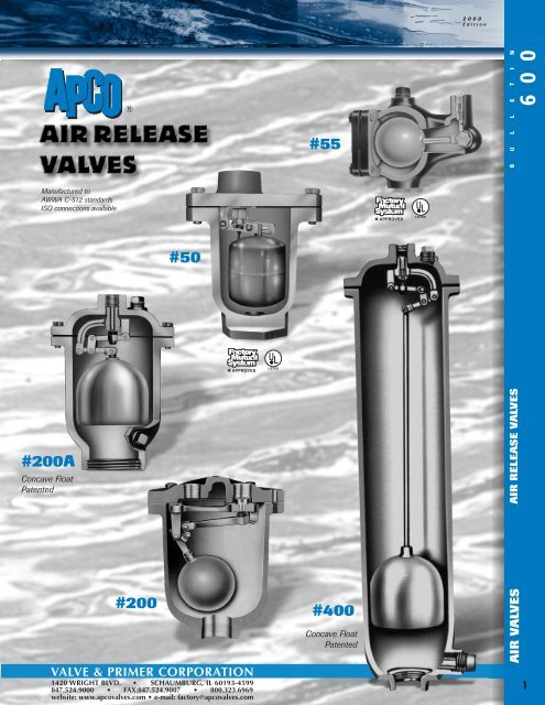
#55<br />
6 0 0<br />
B U L L E T I N<br />
Manufactured to<br />
AWWA C-512 st<strong>and</strong>ards<br />
ISO connections available<br />
#50<br />
#200A<br />
Concave Float<br />
Patented<br />
AIR RELEASE VALVES<br />
#200<br />
VALVE & PRIMER CORPORATION<br />
1420 WRIGHT BLVD. • SCHAUMBURG, IL 60193-4599<br />
847.524.9000 • FAX:847.524.9007 • 800.323.6969<br />
website: www.apcovalves.com • e-mail: factory@apcovalves.com<br />
#400<br />
Concave Float<br />
Patented<br />
AIR VALVES<br />
1151
AIR RELEASE VALVES<br />
WHY <strong>and</strong> WHERE to use An Air Release <strong>Valve</strong> has a small venting orifice <strong>and</strong> is used wherever<br />
air is entrained in water under pressure. These pockets of air increase the resistance to the flow of water. In critical<br />
installations, air can reduce the capacity of a line down to zero. More common is an increased resistance of 10 to 15%.<br />
The increased resistance must be overcome by the pump using more power than necessary to move the required<br />
amount of water. Such a loss can continue unnoticed for years creating excessive power consumption costs. This is a<br />
major reason why all points where air can collect should be equipped with an <strong>APCO</strong> Air Release <strong>Valve</strong>.<br />
HOW TO OPERATE These valves have much smaller orifices than the Air/Vacuum <strong>Valve</strong>s. Their function<br />
is to release small pockets of air which gather at the high points of a system after it is filled <strong>and</strong> under pressure.<br />
The Air Release <strong>Valve</strong> has the ability to open against internal pressure because it has a small orifice <strong>and</strong> a leverage<br />
mechanism which multiplies the force of the float. This force must be greater than the internal pressure across the<br />
orifice in order to open the orifice when a pocket of air needs to be vented. This explains why, as the internal pressure<br />
increases, the orifice decreases in size to facilitate the valve opening.<br />
S I M P L E L E V E R<br />
All <strong>APCO</strong> Air Release <strong>Valve</strong>s<br />
are 100% Hydrostatically factory<br />
tested for ANSI/AWWA<br />
C512 st<strong>and</strong>ards.<br />
#50<br />
1/2, 3/4, 1” Inlet<br />
PHYSICAL DIMENSIONS<br />
Height . . . . . . . . 5 7 ⁄8”<br />
Width . . . . . . . . . 3 3 ⁄4”<br />
Weight . . . . . . . . 6 lbs.<br />
#55<br />
1/2” Inlet<br />
PHYSICAL DIMENSIONS<br />
Height . . . . . . . . 5 ”<br />
Length . . . . . . . . 6 3 ⁄8”<br />
Width . . . . . . . . . 3 5 ⁄16”<br />
Weight . . . . . . . . 5 1 ⁄2 lbs.<br />
#65 MATERIALS OF<br />
3/4” Inlet<br />
CONSTRUCTION<br />
PHYSICAL DIMENSIONS<br />
Height . . . . . . . . 7”<br />
Length . . . . . . . . 8 1 ⁄2”<br />
Width . . . . . . . . . 4 1 ⁄2”<br />
Weight . . . . . . . . 9 lbs.<br />
Body <strong>and</strong> Cover<br />
Cast Iron<br />
Float<br />
Stainless Steel<br />
Seat<br />
Brass-Stainless or Buna-N<br />
St<strong>and</strong>ard pressures up to 175 psi<br />
<strong>and</strong> up to 300 psi with special<br />
orifice.<br />
Specify if operating pressure is<br />
below 20 psi.<br />
St<strong>and</strong>ard pressures up to 175 psi.<br />
<strong>APCO</strong> Uses Stainless Steel Floats Exclusively!<br />
Examine these QUALITY features provided at no extra cost!<br />
1. ASTM QUALITY materials guaranteed throughout<br />
2. Stainless Steel Floats<br />
3. Conserve pumping power — eliminate restricted high points<br />
4. Create maximum pipeline efficiency<br />
Use <strong>APCO</strong> Air Release <strong>Valve</strong>s.<br />
St<strong>and</strong>ard pressures up to 150 psi<br />
Needle<br />
Brass or Stainless Steel<br />
Linkage<br />
Delrin, Bronze or<br />
Stainless Steel<br />
Other internal parts —<br />
Lever Pins, Retaining Rings,<br />
Screws are Stainless Steel,<br />
Bronze or Brass.<br />
NOTE:<br />
Great care is taken in<br />
the choice of materials to<br />
avoid galvanic action!<br />
116 2
WHERE TO INSTALL...<br />
TYPICAL PIPELINE AND POSITION OF NECESSARY<br />
AIR VALVES.<br />
Also install on:<br />
1. Centrifugal pumps<br />
2. Hydropneumatic Tanks<br />
3. Enclosed Systems<br />
4. Sewage Lines<br />
B U L L E T I N<br />
6 0 0<br />
AIR/VACUUM VALVE on pump discharge before check valve (not necessary for pumps with positive suction head) or HYDRAULICALLY<br />
CONTROLLED AIR/VACUUM VALVE where a discharge central valve is normally closed during pump start-up to develop head.<br />
NOTE: INSTALLING MANWAYS AT INTERVALS IN LARGER SIZE PIPELINES PROVIDES AN EXCELLENT POINT TO INSTALL AIR VALVES.<br />
C O M P O U N D L E V E R<br />
#200A<br />
1”, 2” Inlet<br />
PHYSICAL DIMENSIONS<br />
Height . . . . . . . . 10”<br />
Width . . . . . . . . . 7”<br />
Weight . . . . . . . . 20 lbs.<br />
Inlet— 1” or 2” pipe thread<br />
St<strong>and</strong>ard pressures up to 150 psi<br />
<strong>and</strong> up to 300 psi with special<br />
orifice.<br />
Concave float is patented.<br />
#200<br />
2” Inlet<br />
PHYSICAL DIMENSIONS<br />
Height . . . . . . . . 12 1 ⁄2”<br />
Width . . . . . . . . . 9 1 ⁄2”<br />
Weight . . . . . . . . 45 lbs.<br />
Inlet— 2” pipe thread<br />
St<strong>and</strong>ard pressures up to 150 psi<br />
<strong>and</strong> up to 300 psi with special<br />
orifice.<br />
#205<br />
2” Inlet<br />
PHYSICAL DIMENSIONS<br />
Height . . . . . . . . 13”<br />
Width . . . . . . . . . 12”<br />
Weight . . . . . . . . 75 lbs.<br />
Inlet— 2” pipe thread<br />
Flanged inlet available<br />
150 or 300 lb. class<br />
St<strong>and</strong>ard pressures up to 500 psi<br />
<strong>and</strong> up to 800 psi with special<br />
orifice.<br />
#206<br />
#207<br />
6” Inlet<br />
PHYSICAL DIMENSIONS<br />
Height . . . . . . . . 28”<br />
Width . . . . . . . . . 13 1 ⁄2”<br />
Weight . . . . . . . .200 lbs.<br />
Inlet— 6” 125# flange<br />
Discharge orifice . . 1” dia.<br />
HIGH VENTING CAPACITY<br />
St<strong>and</strong>ard pressures up to 150 psi<br />
<strong>and</strong> up to 300 psi with special<br />
orifice.<br />
AIR RELEASE VALVES<br />
FOR SELECTION AND SIZING<br />
OF ALL THE ABOVE AIR VALVES,<br />
SEE BACK PAGE OF THIS BULLETIN<br />
OR ASK FOR <strong>APCO</strong> AIR VALVE<br />
SIZING SOFTWARE.<br />
2” Inlet<br />
PHYSICAL DIMENSIONS<br />
Height . . . . . . . . 14”<br />
Width . . . . . . . . . 12”<br />
Weight . . . . . . . .115 lbs.<br />
Flanged inlet available<br />
400 or <strong>600</strong> lb. class<br />
St<strong>and</strong>ard pressures up to 800 psi<br />
<strong>and</strong> up to 1,500 psi with special<br />
orifice.<br />
AIR VALVES<br />
117 3
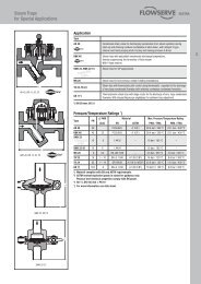
HOW TO SELECT . . .<br />
. . . AND SIZE AN AIR RELEASE<br />
VALVE WHEN A SPECIFIC<br />
VENTING CAPACITY IS<br />
REQUIRED.<br />
A. Enter GRAPH with pressure in system <strong>and</strong><br />
venting capacity required.<br />
B. Read off nearest orifice diameter to intersection<br />
of pressure <strong>and</strong> capacity lines on GRAPH.<br />
C. Enter TABLE BELOW with orifice diameter<br />
<strong>and</strong> select valve which can use this orifice<br />
diameter at the pressure involved.<br />
1500<br />
1000<br />
PRESSURE DIFFERENTIAL ACROSS VALVE IN P.S.I.<br />
500<br />
200<br />
150<br />
100<br />
50<br />
20<br />
10<br />
5<br />
2<br />
VENTING CAPACITY GRAPH FOR AIR RELEASE VALVES<br />
ORIFICE SIZES<br />
1<br />
⁄32<br />
1<br />
0.1 0.2 0.5 1.0 2.0 5.0 10 20 50 100 200 500 1000 2000 5000<br />
VENTING CAPACITY IN CUBIC FEETOFFREEAIRPERMINUTE<br />
1<br />
⁄16<br />
3 ⁄32<br />
1 ⁄8<br />
5 ⁄32 3 ⁄16 7 ⁄32 1 ⁄4 5 ⁄16 3 ⁄8 7 ⁄16 1 ⁄2<br />
3 ⁄4<br />
1<br />
1/2” SHUT-OFF<br />
VALVE<br />
QUICK<br />
DISCONNECT<br />
COUPLING<br />
S E W A G E A I R R E L E A S E<br />
STANDARD OPERATING PRESSURE 175 PSI.<br />
HIGHER PRESSURES AVAILABLE.<br />
#400<br />
#450<br />
CONCAVE<br />
FLOAT<br />
PATENTED<br />
2”<br />
SHUT-OFF<br />
VALVE<br />
BACK<br />
FLUSHING<br />
HOSE<br />
1”<br />
BLOW-OFF<br />
VALVE<br />
2, 3, 4”<br />
PHYSICAL DIMENSIONS<br />
Height . . . . . . . . . . 17 1 ⁄2”<br />
Max. Diameter . . . 7 1 ⁄2”<br />
Weight . . . . . . . . . . 41 lbs.<br />
VALVE WITH ACCESSORIES<br />
Height . . . . . . . . . . 24”<br />
Weight . . . . . . . . . . 55 lbs.<br />
Inlet— 2”, 3” or 4” pipe thread<br />
2, 3, 4”<br />
PHYSICAL DIMENSIONS<br />
Height . . . . . . . . . . 20”<br />
Max. Diameter . . . 9 1 ⁄2”<br />
Weight . . . . . . . . . . 85 lbs.<br />
VALVE WITH ACCESSORIES<br />
Height . . . . . . . . . . 27”<br />
Weight . . . . . . . . . . 118 lbs.<br />
Inlet— 2”, 3” or 4” pipe thread<br />
MODEL INLET<br />
MAXIMUM ORIFICE SIZES WHICH CAN BE USED WITH THE FOLLOWING PRESSURES<br />
SIZE 10 25 50 75 100 125 150 200 250 300 500 800 1500<br />
50<br />
55<br />
65<br />
200A<br />
200<br />
205<br />
206<br />
207<br />
400<br />
450<br />
1<br />
⁄2, 3 ⁄4,1” 3/32 3/32 3/32 3/32 3/32 3/32 3/32 1/16 1/16 1/16 x x x<br />
1/2” 3/32 3/32 3/32 3/32 3/32 3/32 3/32 x x x x x x<br />
3/4” 7/32 7/32 7/32 7/32 1/8 1/8 1/8 x x x x x x<br />
1”,2” 5/16 5/16 5/16 1/4 3/16 3/16 3/16 5/32 5/32 5/32 x x x<br />
2” 1/2 1/2 1/2 1/2 3/8 3/8 3/8 7/32 7/32 7/32 x x x<br />
2” x x x x 1/2 3/8 3/8 7/32 7/32 7/32 7/32 1/8 x<br />
2” x x x x x x x x x x x x 3/32<br />
6” 1 1 1 1 1 1 1 3/4 3/4 3/4 x x x<br />
2”,3”,4”<br />
2”,3”,4”<br />
5/16 5/16 5/16 1/4 1/4 1/4 1/4 3/16 5/32 5/32 x x x<br />
1/2 1/2 1/2 1/2 1/2 1/2 1/2 7/16 7/16 7/16 x x x<br />
STANDARD ORIFICES ON CHART ARE SHADED IN BLUE<br />
118 4<br />
VALVE & PRIMER CORPORATION<br />
1420 WRIGHT BLVD. • SCHAUMBURG, IL 60193-4599<br />
847.524.9000 • FAX:847.524.9007 • 800.323.6969<br />
website: www.apcovalves.com • e-mail: factory@apcovalves.com<br />
VALVE & PRIMER CORPORATION HEREBY RESERVES THE RIGHT TO CHANGE ANY<br />
COMPONENT PARTS WHICH, IN THE OPINION OF ITS ENGINEERING DEPARTMENT,<br />
WILL IMPROVE THE PRODUCT OR INCREASE ITS SERVICEABILITY.<br />
DIMENSIONS ARE FOR ILLUSTRATIVE PURPOSES ONLY. PLEASE CONFIRM ALL DIMENSIONAL<br />
INFORMATION WITH VALVE & PRIMER CORPORATION ENGINEERING DEPARTMENT.