"C" Series â MGS Adjustable Speed Drive Selection Data - Womack ...
"C" Series â MGS Adjustable Speed Drive Selection Data - Womack ...
"C" Series â MGS Adjustable Speed Drive Selection Data - Womack ...

You also want an ePaper? Increase the reach of your titles
YUMPU automatically turns print PDFs into web optimized ePapers that Google loves.
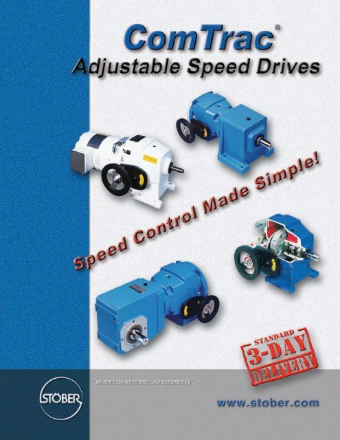
ComTrac ® <strong>Adjustable</strong> <strong>Speed</strong> <strong>Drive</strong>s<br />
Company Profile<br />
STÖBER was first established in Germany in 1934, and has<br />
been a pioneer in the gearing industry ever since. Through<br />
constant innovation, STÖBER today is known for high precision,<br />
high efficiency and low noise in their various gearing technologies.<br />
STOBER ® <strong>Drive</strong>s Inc., located in Maysville KY, manufactures<br />
products to serve the North American market.<br />
Beginning with the ComTrac ® Mechanical Variable <strong>Speed</strong><br />
Reducers, STÖBER established itself as a technology leader,<br />
later adding the innovative <strong>MGS</strong> ® Modular Gear System to the<br />
product offering. <strong>MGS</strong> ® Food and Beverage Reducers excel in<br />
the harshest of washdown environments.<br />
STÖBER next introduced ServoFit ® Precision Planetary<br />
Gearheads, establishing the standard for low noise and low<br />
backlash in the servo industry. The recent introduction of the<br />
SMS ® ServoFit Modular System gearheads adds a high<br />
precision, cost effective alternative to the servo market.<br />
STÖBER has the broadest offering of speed reducers available,<br />
providing one stop shopping for both the industrial market and<br />
the rapidly growing motion control market.<br />
On behalf of the worldwide family of STÖBER employees, we<br />
thank you for trying our products and pledge to continue to meet<br />
your product and service needs with the newest solutions.<br />
Sincerely,<br />
Bernd Stöber, Chairman<br />
Stöber Antriebstechnik GmbH<br />
Peter Feil, VP/General Manager<br />
STOBER <strong>Drive</strong>s, Inc.<br />
Table of Contents<br />
ComTrac <strong>Adjustable</strong> <strong>Speed</strong> <strong>Drive</strong>s<br />
Advantages and Features ................................................. 2<br />
Performance....................................................................... 3<br />
Washdown Duty ................................................................. 4<br />
Operating Characteristics .................................................. 5<br />
Ratings and Dimension<br />
.50 HP ...................................................................... 6<br />
.75 HP ...................................................................... 7<br />
1.0 HP ...................................................................... 8<br />
1.5 HP ...................................................................... 9<br />
2.0 HP .................................................................... 10<br />
3.0 HP .................................................................... 11<br />
5.0 HP .................................................................... 12<br />
7.50 HP .................................................................. 13<br />
10.0 HP .................................................................. 14<br />
Electric Remote Control (ERC) ....................................... 15<br />
<strong>Selection</strong> and Performance Characteristics ................... 16<br />
Installation Instructions .................................................... 18<br />
Maintenance and Lubrication .......................................... 20<br />
"C" <strong>Series</strong> <strong>MGS</strong> <strong>Adjustable</strong> <strong>Speed</strong> <strong>Drive</strong>s<br />
Performance Specifications ............................................ 21<br />
Ratings ............................................................................. 22<br />
Dimensions ...................................................................... 40<br />
Mounting Positions .......................................................... 78<br />
"F" <strong>Series</strong> <strong>MGS</strong> <strong>Adjustable</strong> <strong>Speed</strong> <strong>Drive</strong>s<br />
Performance Specifications ............................................ 43<br />
Ratings ............................................................................. 44<br />
Dimension ........................................................................ 50<br />
Mounting Positions .......................................................... 78<br />
"K" <strong>Series</strong> <strong>MGS</strong> <strong>Adjustable</strong> <strong>Speed</strong> <strong>Drive</strong>s<br />
Performance Specifications ............................................ 53<br />
Ratings ............................................................................. 54<br />
Dimensions ...................................................................... 72<br />
Mounting Positions .......................................................... 79<br />
Mounting Hollow Output Units ......................................... 76<br />
Mounting Positions .......................................................... 77<br />
Terms and Conditions ..................................................... 80<br />
STOBER <strong>Drive</strong>s Inc. • ComTrac2007 • www.stober.com 1
ComTrac ® <strong>Adjustable</strong> <strong>Speed</strong> <strong>Drive</strong>s<br />
Advantages:<br />
You're probably already aware of the many common-sense<br />
advantages offered by traction-type adjustable speed drives like<br />
the ComTrac drive. When compared to mechanical belt-type, or<br />
electrical adjustable speed drives, traction type drives offer:<br />
• Often, a lower initial cost.<br />
• Few worries about motor overheating during low speed<br />
operation.<br />
• No motor brushes to replace.<br />
• Very compact and lightweight when compared to other<br />
mechanical drives.<br />
• Simple design with few rotating components to wear or<br />
replace.<br />
• Easily serviced by semiskilled personnel<br />
• Low maintenance – doesn't need to be cycled through its<br />
speed range to prevent component damage.<br />
• 2 year warranty–your assurance of satisfactory product<br />
performance.<br />
Cast iron housing – High tensile strength cast iron housing for<br />
long service life in demanding applications.<br />
Stainless steel nameplate.<br />
Two year warranty – Every ComTrac unit is backed by a twoyear<br />
warranty.<br />
Delivery – ComTrac units are shipped in 3 days or less.<br />
<strong>Selection</strong>:<br />
In general, proper selection of a ComTrac drive is as easy as<br />
the drive is to operate.<br />
1. Establish the maximum horsepower required by the driven<br />
machine at maximum speed.<br />
2. Select the drive which meets or exceeds the maximum HP<br />
rating of the driven machine at maximum speed.<br />
Features:<br />
<strong>Drive</strong> cone – The drive cone is made from ductile iron and is<br />
precision ground for long service life. It contains inner air<br />
chambers for efficient heat dissipation. It is independently<br />
supported by a shielded bearing mounted into the motor<br />
adapter/slide – not just by the motor bearing.<br />
Traction ring – ComTrac's self-lubrication traction ring is made<br />
from a proprietary material that provides exceptional resistance<br />
to wear and high temperatures. When replacement is necessary,<br />
only the ring and not the entire friction ring mounting<br />
flange is replaced.<br />
<strong>Speed</strong> adjustment – ComTrac's rack and pinion speed<br />
adjustment system features stainless steel components to<br />
resist corrosion and is dust resistant by design. The stainless<br />
steel pinion shaft and ductile iron rack are designed to provide<br />
assured speed adjustments in the wettest, dirtiest environments.<br />
Handwheel control – Handwheel control with a position<br />
indicator is standard on every ComTrac drive. Remote speed<br />
controls and overspeed protection is also available.<br />
All ComTrac drives are shipped with the handwheel positioned<br />
on the left as viewed from the output shaft end of the drive. The<br />
handwheel can be quickly and easily moved to the right side by<br />
using the tools and instructions included with the drive.<br />
Mounting position – ComTrac drives can be mounted in<br />
virtually any position.<br />
NEMA C-face input – All ComTrac drives feature a NEMA C-<br />
face input – that means standard off-the-shelf motors, available<br />
locally. ComTrac's patented corrosion resistant collet clamp ring<br />
makes motor shaft attachment fast and simple. The proper hex<br />
wrenches are included with each unit in the motor access cover.<br />
When the motor must be replaced, it can be done easily and<br />
quickly without disassembly of the entire drive.<br />
In addition, the 0F unit is standard with a NEMA C-face output<br />
flange. It enables you to add adjustable speed capability to new<br />
or existing applications.<br />
Torque compensator – The torque compensator assembly<br />
features high-capacity cylindrical roller bearings – not needle<br />
bearings – for long life and quiet operation. The design allows<br />
speed changes during operation or while the drive is at rest.<br />
The load compensating cams precisely match the pressure<br />
between the drive cone and the traction ring in proportion to the<br />
load torque.<br />
Part No. Example:<br />
TD47 0 F K182 W<br />
Traction <strong>Drive</strong> Model/Size<br />
0 – Non-geared<br />
F – Flange Mount<br />
Input for NEMA Frame Size (182TC)<br />
Washdown/Severe Duty (Option)<br />
TD47 0 N K182 W<br />
Traction <strong>Drive</strong> Model/Size<br />
0 – Non-geared<br />
N – Foot Mount<br />
Input for NEMA Frame Size (182TC)<br />
Washdown/Severe Duty (Option)<br />
<strong>Speed</strong> Control Made Simple!<br />
2 STOBER <strong>Drive</strong>s Inc. • ComTrac2007 • www.stober.com
ComTrac ® <strong>Adjustable</strong> <strong>Speed</strong> <strong>Drive</strong>s<br />
Performance Specifications:<br />
• Horsepower ratings – from 1 /2 to 10<br />
• Output speeds – available from 2180 to 311 RPM<br />
• <strong>Speed</strong> range – 5:1 to 7:1<br />
• Output torques – up to 496 in.lbs.<br />
• NEMA frames – from 56C to 215TC<br />
Access Cover with wrenches<br />
Friction (Traction)<br />
Ring Flange<br />
Assembly<br />
Collet Clamp Ring<br />
Torque Compensator<br />
NEMA C-face Input<br />
<strong>Drive</strong> Cone<br />
Handwheel<br />
<strong>Speed</strong> Adjustment Dial<br />
Cast Iron Housing<br />
STOBER <strong>Drive</strong>s Inc. • ComTrac2007 • www.stober.com 3
ComTrac ® <strong>Adjustable</strong> <strong>Speed</strong> <strong>Drive</strong>s<br />
Washdown/Outdoor Service/ Severe Duty<br />
Advantages:<br />
STÖBER has developed a severe duty protection package for<br />
ComTrac drives which significantly improves the drives' ability<br />
to withstand the effects of outdoor use, exposure to excessively<br />
humid or acidic environments, or spray washed with water or<br />
caustic fluids.<br />
The ComTrac severe duty package includes corrosion protection<br />
for all functional components and housings including:<br />
• <strong>Drive</strong> cone<br />
• Motor clamping ring<br />
• Motor slide and rack<br />
• Bearing housing<br />
• Main housing cover<br />
To prevent corrosion, these components are protected by a<br />
special heat treatment process similar to chrome plating.<br />
Features:<br />
<strong>Drive</strong> cone – Corrosion protected drive cone extends cone and<br />
ring life.<br />
<strong>Speed</strong> adjustment – The protected motor slide, stainless steel<br />
control shaft with pinion, and greased rack and slideway assure<br />
the proper speed adjustment.<br />
NEMA C-face input – ComTrac's patented corrosion resistent<br />
collet clamp ring assures ease of motor replacement.<br />
External surface – All external surfaces are protected with a<br />
special acid-resistant epoxy paint to prevent corrosion and<br />
lubricant contamination.<br />
Internal surface – All internal surfaces and bearing housing are<br />
protected with a special anticorrosion paint.<br />
Double seals – Double output seals can be provided for<br />
maximum protection in very harsh environments.<br />
Mounting position – ComTrac drives in a vertical mounting<br />
position (output shaft down) must be adapted to allow water to<br />
drain.<br />
Stainless steel nameplate – Other features of the severe duty<br />
unit are: stainless steel nameplate, rivets, and chrome plated<br />
bolts.<br />
Two year warranty – Like the standard drive, this ComTrac unit<br />
is also backed by a two-year warranty.<br />
Delivery – ComTrac units are shipped in 3 days or less.<br />
4 STOBER <strong>Drive</strong>s Inc. • ComTrac2007 • www.stober.com
ComTrac ® <strong>Adjustable</strong> <strong>Speed</strong> <strong>Drive</strong>s<br />
Operating Characteristics<br />
Operation:<br />
The ComTrac drive is an adjustable speed traction drive. Its<br />
operation is based upon the transfer of power between the<br />
motor mounted drive cone and the traction ring. The drive<br />
cone and the traction ring are forced together to transmit<br />
torque through the use of a spring loaded torque compensator<br />
assembly.<br />
At rest, the spring inside the torque compensator produces<br />
only a small contact pressure between the drive cone and<br />
traction ring. Unlike other mechanical drives, the minimal<br />
spring pressure allows speed changes to be made while the<br />
drive is at rest.<br />
As the drive is started, the load compensating cams move<br />
against each other to increase pressure between the drive<br />
cone and traction ring. During operation, the load compensating<br />
cams maintain the proper amount of pressure between<br />
the drive cone and traction ring in proportion to the output<br />
load torque required.<br />
<strong>Speed</strong> changes are made by changing the relative running<br />
diameters of the drive cone and the traction ring. As the motor<br />
and drive cone are moved upward, the contact point between<br />
the cone and ring moves to the faster running outer diameter of<br />
the drive cone and output speed increases. As the motor and<br />
drive cone are lowered, the contact point between the cone<br />
and ring moves to the slower running center of the drive cone<br />
and output speed decreases.<br />
Movement of the motor and drive cone are accomplished<br />
through the use of a handwheel attached to a rack and pinion.<br />
By turning the handwheel, the motor is easily raised or lowered<br />
on the dust resistant motor slide. <strong>Speed</strong> changes can also be<br />
made through the use of an optional electric remote control<br />
which replaces the handwheel.<br />
<strong>Speed</strong> Control Made Simple!<br />
• Turn the handwheel – pinion moves the rack on the motor slide – up or down.<br />
Contact Point<br />
Contact Point<br />
Maximum speed – motor slide up.<br />
Minimum speed – motor slide down.<br />
STOBER <strong>Drive</strong>s Inc. • ComTrac2007 • www.stober.com 5
ComTrac ® <strong>Adjustable</strong> <strong>Speed</strong> <strong>Drive</strong>s<br />
.50 HP @ 1750 RPM<br />
All TD27 units are available with 56C and 143TC input.<br />
10.67<br />
.1875 +.0000 / -.0005<br />
x 1.38 Lg.<br />
8.86<br />
1.87<br />
1.65<br />
#12-24 NC<br />
.71<br />
5.67<br />
5.875<br />
3<br />
/8-16 NC<br />
Motor Slide<br />
Adjustment<br />
2.09<br />
4.500<br />
+.000<br />
-.001<br />
6.50<br />
1.57<br />
4.41<br />
8.11<br />
5.55<br />
4.92<br />
4.72<br />
.47<br />
.625<br />
+.0000<br />
-.0005<br />
.12<br />
2.06<br />
M10<br />
.20 x .26<br />
6.22<br />
Part No. – 33 lbs.<br />
TD270FK56<br />
Flange Style<br />
56C Input and Output<br />
8.07<br />
.5903<br />
.51<br />
+.0000<br />
-.0005 1.30<br />
4.29<br />
Handwheel Shaft Dimensions<br />
Constant Horsepower Range<br />
Constant Torque Range<br />
MAXIMUM TRANSITION (2) MINIMUM<br />
RPM (1) in.lbs. HP RPM (1) in.lbs. HP RPM (1) in.lbs. HP<br />
2,180 12.2 0.42 334 66 0.35 311 66 0.33<br />
All ratings shown are based on 1750 RPM motor speed and are rated to provide constant torque through the entire speed range. Contact STOBER<br />
for constant horsepower applications. MOTOR MUST BE ORDERED SEPARATELY.<br />
1)<br />
<strong>Speed</strong> tolerance at rated load is ±3%. At less than rated load, minimum speed may increase 5%.<br />
2)<br />
The ComTrac drive operates at constant horsepower above transition values and at constant torque below transition values. Note shaded area.<br />
Engineering advances may cause slight changes to the information shown.<br />
.1875<br />
10.67<br />
+.0000 / -.0005<br />
x 1.38 Lg.<br />
8.86<br />
#12-24 NC<br />
5.67<br />
1.97<br />
.71<br />
6.22<br />
1.87<br />
Motor Slide<br />
1.65 Output Shaft<br />
Adjustment<br />
2.09<br />
9.29<br />
4.92<br />
8.50<br />
5.118<br />
.625<br />
5.55 (3) +.000<br />
+.0000 -.001<br />
-.0005<br />
3.54<br />
1.50<br />
2.56<br />
4.92<br />
8.07<br />
2.87<br />
.51<br />
1.38<br />
5.51<br />
6.69<br />
.71<br />
Part No. – 33 lbs.<br />
TD270NK56<br />
Foot Mount<br />
56C Input<br />
(3)<br />
Motor is lower than the base of the ComTrac. See Page 15.<br />
6 STOBER <strong>Drive</strong>s Inc. • ComTrac2007 • www.stober.com
ComTrac ® <strong>Adjustable</strong> <strong>Speed</strong> <strong>Drive</strong>s<br />
.75 HP @ 1750 RPM<br />
All TD27 units are available with 56C and 143TC input.<br />
10.67<br />
.1875 +.0000 / -.0005<br />
x 1.38 Lg.<br />
8.86<br />
1.87<br />
1.65<br />
#12-24 NC<br />
.71<br />
5.67<br />
5.875<br />
3<br />
/8-16 NC<br />
Motor Slide<br />
Adjustment<br />
2.09<br />
4.500<br />
+.000<br />
-.001<br />
6.50<br />
1.57<br />
4.41<br />
8.11<br />
5.55<br />
4.92<br />
4.72<br />
.47<br />
.625<br />
+.0000<br />
-.0005<br />
.12<br />
2.06<br />
M10<br />
.20 x .26<br />
6.22<br />
8.07<br />
Part No. – 33 lbs.<br />
4.92<br />
8.50<br />
5.118<br />
5.55 (3) .625 +.0000 -.001<br />
3.54<br />
-.0005<br />
.5903<br />
.51<br />
TD270FK56<br />
+.0000<br />
-.0005 1.30<br />
4.29<br />
Flange Style<br />
Handwheel Shaft Dimensions<br />
56C Input and Output<br />
Constant Horsepower Range<br />
Constant Torque Range<br />
MAXIMUM TRANSITION (2) MINIMUM<br />
RPM (1) in.lbs. HP RPM (1) in.lbs. HP RPM (1) in.lbs. HP<br />
2,180 18.3 0.63 582 66 0.61 311 66 0.33<br />
All ratings shown are based on 1750 RPM motor speed and are rated to provide constant torque through the entire speed range. Contact STOBER for<br />
constant horsepower applications. MOTOR MUST BE ORDERED SEPARATELY.<br />
1)<br />
<strong>Speed</strong> tolerance at rated load is ±3%. At less than rated load, minimum speed may increase 5%.<br />
2)<br />
The ComTrac drive operates at constant horsepower above transition values and at constant torque below transition values. Note shaded area.<br />
Engineering advances may cause slight changes to the information shown.<br />
.1875<br />
10.67<br />
+.0000 / -.0005<br />
x 1.38 Lg.<br />
8.86<br />
#12-24 NC<br />
5.67<br />
1.97<br />
.71<br />
6.22<br />
1.87<br />
Motor Slide<br />
Adjustment<br />
1.65 Output Shaft<br />
2.09<br />
9.29<br />
2.56<br />
1.50<br />
2.87<br />
4.92<br />
8.07<br />
(3)<br />
Motor is lower than the base of the ComTrac. See Page 15.<br />
.51<br />
1.38<br />
6.69<br />
5.51<br />
.71<br />
Part No. – 33 lbs.<br />
TD270NK56<br />
Foot Mount<br />
56C Input<br />
STOBER <strong>Drive</strong>s Inc. • ComTrac2007 • www.stober.com 7
ComTrac ® <strong>Adjustable</strong> <strong>Speed</strong> <strong>Drive</strong>s<br />
1.0 HP @ 1750 RPM<br />
All TD27 units are available with 56C and 143TC input.<br />
10.67<br />
.1875 +.0000 / -.0005<br />
x 1.38 Lg.<br />
8.86<br />
1.87<br />
1.65<br />
#12-24 NC<br />
.71<br />
5.67<br />
5.875<br />
3<br />
/8-16 NC<br />
Motor Slide<br />
Adjustment<br />
2.09<br />
4.500<br />
+.000<br />
-.001 6.50<br />
1.57<br />
4.41<br />
8.11<br />
5.55<br />
4.92<br />
4.72<br />
Part No. – 33 lbs.<br />
TD270FK143<br />
Flange Style<br />
143TC Input<br />
56C Output<br />
.47<br />
8.07<br />
.625<br />
+.0000<br />
-.0005<br />
.12<br />
2.06<br />
M10<br />
.20 x .26<br />
.5903<br />
.51<br />
+.0000<br />
-.0005 1.30<br />
4.29<br />
Handwheel Shaft Dimensions<br />
6.22<br />
Constant Horsepower Range<br />
Constant Torque Range<br />
MAXIMUM TRANSITION (2) MINIMUM<br />
RPM (1) in.lbs. HP RPM (1) in.lbs. HP RPM (1) in.lbs. HP<br />
2,180 24.4 0.84 821 66 0.86 311 66 0.33<br />
All ratings shown are based on 1750 RPM motor speed and are rated to provide constant torque through the entire speed range. Contact STOBER<br />
for constant horsepower applications. MOTOR MUST BE ORDERED SEPARATELY.<br />
1)<br />
<strong>Speed</strong> tolerance at rated load is ±3%. At less than rated load, minimum speed may increase 5%.<br />
2)<br />
The ComTrac drive operates at constant horsepower above transition values and at constant torque below transition values. Note shaded area.<br />
Engineering advances may cause slight changes to the information shown.<br />
.1875<br />
10.67<br />
+.0000 / -.0005<br />
x 1.38 Lg.<br />
8.86<br />
#12-24 NC<br />
5.67<br />
1.97<br />
.71<br />
6.22<br />
1.87<br />
Motor Slide<br />
1.65 Output Shaft<br />
Adjustment<br />
2.09<br />
9.29<br />
4.92<br />
8.50<br />
5.118<br />
5.55 (3) .625 +.000<br />
+.0000<br />
-.001<br />
3.54<br />
-.0005<br />
Part No. – 33 lbs.<br />
TD270NK143<br />
Foot Mount<br />
143TC Input<br />
1.50<br />
2.56<br />
4.92<br />
8.07<br />
2.87<br />
.51<br />
1.38<br />
.71<br />
5.51<br />
6.69<br />
(3)<br />
Motor is lower than the base of the ComTrac. See Page 15.<br />
8 STOBER <strong>Drive</strong>s Inc. • ComTrac2007 • www.stober.com
ComTrac ® <strong>Adjustable</strong> <strong>Speed</strong> <strong>Drive</strong>s<br />
1.5 HP @ 1750 RPM<br />
11.69<br />
9.88<br />
2.24<br />
1.97<br />
1<br />
/4-20 NC<br />
.1875 +.0000 / -.0005<br />
x 1.77 Lg.<br />
.96<br />
5.91<br />
5.875<br />
3<br />
/8-16 NC<br />
Motor Slide<br />
Adjustment<br />
2.17<br />
4.500<br />
+.000<br />
-.001<br />
6.50<br />
2.05<br />
4.37<br />
9.72<br />
5.67<br />
4.92<br />
5.94<br />
9.09<br />
.47<br />
.875<br />
+.0000<br />
-.0005<br />
.12<br />
2.13<br />
M10<br />
.20 x .26<br />
.5903<br />
+.0000<br />
-.0005 1.30<br />
.51<br />
4.53<br />
Handwheel Shaft Dimensions<br />
6.69<br />
Part No. – 51 lbs.<br />
TD370FK145<br />
Flange Style<br />
145TC Input<br />
143TC Output<br />
Constant Horsepower Range<br />
Constant Torque Range<br />
MAXIMUM TRANSITION (2) MINIMUM<br />
RPM (1) in.lbs. HP RPM (1) in.lbs. HP RPM (1) in.lbs. HP<br />
2,100 38 1.27 856 97 1.31 420 97 0.64<br />
All ratings shown are based on 1750 RPM motor speed and are rated to provide constant torque through the entire speed range. Contact STOBER for<br />
constant horsepower applications. MOTOR MUST BE ORDERED SEPARATELY.<br />
1)<br />
<strong>Speed</strong> tolerance at rated load is ±3%. At less than rated load, minimum speed may increase 5%.<br />
2)<br />
The ComTrac drive operates at constant horsepower above transition values and at constant torque below transition values. Note shaded area.<br />
Engineering advances may cause slight changes to the information shown.<br />
11.69<br />
9.88<br />
1<br />
/4-20 NC<br />
.1875<br />
+.0000 / -.0005<br />
x 1.77 Lg.<br />
5.91<br />
Motor Slide<br />
Adjustment<br />
2.17<br />
2.40<br />
2.25<br />
1.97<br />
Output Shaft<br />
.96<br />
6.69<br />
10.59<br />
5.67<br />
.875<br />
+.0000<br />
-.0005<br />
6.299<br />
+.000<br />
-.001<br />
4.92<br />
4.25<br />
10.08<br />
1.30<br />
2.36<br />
5.28<br />
9.09<br />
4.02<br />
.55<br />
6.85<br />
1.65<br />
5.71<br />
.83<br />
Part No. – 51 lbs.<br />
TD370NK145<br />
Foot Mount<br />
145TC Input<br />
STOBER <strong>Drive</strong>s Inc. • ComTrac2007 • www.stober.com 9
ComTrac ® <strong>Adjustable</strong> <strong>Speed</strong> <strong>Drive</strong>s<br />
2.0 HP @ 1750 RPM<br />
11.69<br />
9.88<br />
2.24<br />
1.97<br />
1<br />
/4-20 NC<br />
.1875 +.0000 / -.0005<br />
x 1.77 Lg.<br />
.96<br />
5.91<br />
5.875<br />
3<br />
/8-16 NC<br />
Motor Slide<br />
Adjustment<br />
2.17<br />
4.500<br />
+.000<br />
-.001 6.50<br />
2.05<br />
4.37<br />
9.72<br />
5.67<br />
4.92<br />
5.94<br />
Part No. – 51 lbs.<br />
TD370FK145<br />
Flange Style<br />
145TC Input<br />
143TC Output<br />
.47<br />
9.09<br />
.875<br />
+.0000<br />
-.0005<br />
.12<br />
2.13<br />
M10<br />
.20 x .26<br />
.5903<br />
.51<br />
+.0000<br />
-.0005 1.30<br />
4.53<br />
Handwheel Shaft Dimensions<br />
6.69<br />
Constant Horsepower Range<br />
Constant Torque Range<br />
MAXIMUM TRANSITION (2) MINIMUM<br />
RPM (1) in.lbs. HP RPM (1) in.lbs. HP RPM (1) in.lbs. HP<br />
2,100 51 1.70 1,162 97 1.79 420 97 0.65<br />
All ratings shown are based on 1750 RPM motor speed and are rated to provide constant torque through the entire speed range. Contact STOBER<br />
for constant horsepower applications. MOTOR MUST BE ORDERED SEPARATELY.<br />
1)<br />
<strong>Speed</strong> tolerance at rated load is ±3%. At less than rated load, minimum speed may increase 5%.<br />
2)<br />
The ComTrac drive operates at constant horsepower above transition values and at constant torque below transition values. Note shaded area.<br />
Engineering advances may cause slight changes to the information shown.<br />
11.69<br />
9.88<br />
1<br />
/4-20 NC<br />
.1875<br />
+.0000 / -.0005<br />
x 1.77 Lg.<br />
5.91<br />
Motor Slide<br />
Adjustment<br />
2.17<br />
2.40<br />
2.25<br />
1.97<br />
Output Shaft<br />
.96<br />
6.69<br />
10.59<br />
5.67<br />
.875<br />
+.0000<br />
-.0005<br />
6.299<br />
+.000<br />
-.001<br />
4.92<br />
4.25<br />
10.08<br />
Part No. – 51 lbs.<br />
TD370NK145<br />
Foot Mount<br />
145TC Input<br />
1.30<br />
2.36<br />
5.28<br />
9.09<br />
4.02<br />
.55<br />
1.65<br />
5.71<br />
6.85<br />
.83<br />
10 STOBER <strong>Drive</strong>s Inc. • ComTrac2007 • www.stober.com
ComTrac ® <strong>Adjustable</strong> <strong>Speed</strong> <strong>Drive</strong>s<br />
3.0 HP @ 1750 RPM<br />
12.48<br />
.1875 +.0000 / -.0005<br />
x 1.77 Lg.<br />
9.96<br />
2.24<br />
1.97<br />
1<br />
/4-20 NC<br />
.96<br />
6.81<br />
5.875<br />
3<br />
/8-16 NC<br />
Motor Slide<br />
Adjustment<br />
2.80<br />
4.500<br />
+.000<br />
-.001 6.50<br />
2.60<br />
5.59<br />
11.57<br />
7.20<br />
6.30<br />
6.93<br />
.47<br />
9.13<br />
.875<br />
+.0000<br />
-.0005<br />
.12<br />
2.13<br />
M10<br />
.20 x .26<br />
.5903<br />
.51<br />
+.0000<br />
-.0005 1.30<br />
5.24<br />
Handwheel Shaft Dimensions<br />
8.11<br />
Part No. – 59 lbs.<br />
TD470FK182<br />
Flange Style<br />
182TC Input<br />
143TC Output<br />
Constant Horsepower Range<br />
Constant Torque Range<br />
MAXIMUM TRANSITION (2) MINIMUM<br />
RPM (1) in.lbs. HP RPM (1) in.lbs. HP RPM (1) in.lbs. HP<br />
2,100 81 2.70 970 177 2.72 420 177 1.18<br />
All ratings shown are based on 1750 RPM motor speed and are rated to provide constant torque through the entire speed range. Contact STOBER for<br />
constant horsepower applications. MOTOR MUST BE ORDERED SEPARATELY.<br />
1)<br />
<strong>Speed</strong> tolerance at rated load is ±3%. At less than rated load, minimum speed may increase 5%.<br />
2)<br />
The ComTrac drive operates at constant horsepower above transition values and at constant torque below transition values. Note shaded area.<br />
Engineering advances may cause slight changes to the information shown.<br />
12.48<br />
9.96<br />
1<br />
/4-20 NC<br />
.1875<br />
+.0000 / -.0005<br />
x 1.77 Lg.<br />
6.81<br />
Motor Slide<br />
Adjustment<br />
2.80<br />
2.32<br />
2.25<br />
1.97<br />
Output Shaft<br />
.96<br />
8.11<br />
12.28<br />
7.20<br />
.875<br />
+.0000<br />
-.0005<br />
7.087<br />
+.000<br />
-.001<br />
6.30<br />
4.49<br />
11.73<br />
1.26<br />
3.54<br />
5.43<br />
9.13<br />
2.95<br />
.55<br />
2.17<br />
8.86<br />
7.48<br />
.98<br />
Part No. – 59 lbs.<br />
TD470NK182<br />
Foot Mount<br />
182TC Input<br />
STOBER <strong>Drive</strong>s Inc. • ComTrac2007 • www.stober.com 11
ComTrac ® <strong>Adjustable</strong> <strong>Speed</strong> <strong>Drive</strong>s<br />
5.0 HP @ 1750 RPM<br />
15.98<br />
13.39<br />
2.75<br />
2.40<br />
3<br />
/8-16 NC<br />
.25 +.0000 / -.0005<br />
x 2.20 Lg.<br />
1.24<br />
8.31<br />
7.250<br />
1<br />
/2-13 NC<br />
Motor Slide<br />
Adjustment<br />
3.11<br />
8.11<br />
8.500<br />
+.000<br />
-.001<br />
9.00<br />
7.87<br />
3.35<br />
6.30<br />
8.11<br />
13.43<br />
Part No. – 88 lbs.<br />
TD570FK184<br />
Flange Style<br />
184TC Input<br />
182TC Output<br />
.83<br />
12.32<br />
1.125<br />
+.0000<br />
-.0005<br />
.26<br />
2.62<br />
M12<br />
.20 x .30<br />
.7871<br />
.59<br />
+.0000<br />
-.0005 1.50<br />
6.54<br />
Handwheel Shaft Dimensions<br />
9.61<br />
Constant Horsepower Range<br />
Constant Torque Range<br />
MAXIMUM TRANSITION (2) MINIMUM<br />
RPM (1) in.lbs. HP RPM (1) in.lbs. HP RPM (1) in.lbs. HP<br />
2,100 137 4.56 1,102 266 4.65 420 266 1.77<br />
All ratings shown are based on 1750 RPM motor speed and are rated to provide constant torque through the entire speed range. Contact STOBER<br />
for constant horsepower applications. MOTOR MUST BE ORDERED SEPARATELY.<br />
1)<br />
<strong>Speed</strong> tolerance at rated load is ±3%. At less than rated load, minimum speed may increase 5%.<br />
2)<br />
The ComTrac drive operates at constant horsepower above transition values and at constant torque below transition values. Note shaded area.<br />
Engineering advances may cause slight changes to the information shown.<br />
15.98<br />
13.39<br />
3<br />
/8-16 NC<br />
.250<br />
+.0000 / -.0005<br />
x 2.20 Lg.<br />
8.31<br />
2.87<br />
1.24<br />
9.61<br />
Motor Slide<br />
Adjustment<br />
3.11<br />
2.75<br />
2.40<br />
Output Shaft<br />
14.57<br />
8.11<br />
1.125<br />
+.0000<br />
-.0005<br />
8.268<br />
+.000<br />
-.001<br />
7.87<br />
4.92<br />
13.58<br />
Part No. – 88 lbs.<br />
TD570NK184<br />
Foot Mount<br />
184TC Input<br />
2.36<br />
3.74<br />
7.60<br />
12.32<br />
4.37<br />
.67<br />
2.71<br />
10.75<br />
9.06<br />
1.22<br />
12 STOBER <strong>Drive</strong>s Inc. • ComTrac2007 • www.stober.com
ComTrac ® <strong>Adjustable</strong> <strong>Speed</strong> <strong>Drive</strong>s<br />
7.5 HP @ 1750 RPM<br />
16.14<br />
.25 +.0000 / -.0005<br />
x 2.20 Lg.<br />
13.54<br />
2.75<br />
2.40<br />
3<br />
/8-16 NC<br />
1.24<br />
9.17<br />
7.250<br />
1<br />
/2-13 NC<br />
Motor Slide<br />
Adjustment<br />
3.86<br />
9.02<br />
8.500<br />
+.000<br />
-.001<br />
9.00<br />
7.87<br />
3.54<br />
7.13<br />
8.66<br />
14.84<br />
.26<br />
.83<br />
12.48<br />
1.125<br />
+.0000<br />
-.0005<br />
2.62<br />
M12<br />
.20 x .30<br />
.7871<br />
+.0000<br />
-.0005 1.50<br />
.59<br />
7.40<br />
Handwheel Shaft Dimensions<br />
11.34<br />
Part No. – 130 lbs.<br />
TD670FK213<br />
Flange Style<br />
213TC Input<br />
182TC Output<br />
Constant Horsepower Range<br />
Constant Torque Range<br />
MAXIMUM TRANSITION (2) MINIMUM<br />
RPM (1) in.lbs. HP RPM (1) in.lbs. HP RPM (1) in.lbs. HP<br />
2,100 206 6.86 1,216 363 7.00 420 363 2.42<br />
All ratings shown are based on 1750 RPM motor speed and are rated to provide constant torque through the entire speed range. Contact STOBER for<br />
constant horsepower applications. MOTOR MUST BE ORDERED SEPARATELY.<br />
1)<br />
<strong>Speed</strong> tolerance at rated load is ±3%. At less than rated load, minimum speed may increase 5%.<br />
2)<br />
The ComTrac drive operates at constant horsepower above transition values and at constant torque below transition values. Note shaded area.<br />
Engineering advances may cause slight changes to the information shown.<br />
16.14<br />
13.54<br />
3<br />
/8-16 NC<br />
.250<br />
+.0000 / -.0005<br />
x 2.20 Lg.<br />
9.17<br />
2.95<br />
1.24<br />
11.34<br />
2.75<br />
Motor Slide<br />
Adjustment<br />
3.86<br />
2.40<br />
Output Shaft<br />
16.18<br />
9.02<br />
1.125<br />
+.0000<br />
-.0005<br />
9.055<br />
+.000<br />
-.001<br />
7.87<br />
5.51<br />
15.24<br />
2.52<br />
3.74<br />
7.70<br />
12.48<br />
4.37<br />
.67<br />
2.64<br />
9.06<br />
10.75<br />
1.22<br />
Part No. – 130 lbs.<br />
TD670NK213<br />
Foot Mount<br />
213TC Input<br />
STOBER <strong>Drive</strong>s Inc. • ComTrac2007 • www.stober.com 13
ComTrac ® <strong>Adjustable</strong> <strong>Speed</strong> <strong>Drive</strong>s<br />
10.0 HP @ 1750 RPM<br />
18.66<br />
.3125 +.0000 / -.0005<br />
x 2.87 Lg.<br />
16.06<br />
3.25<br />
2.99<br />
3<br />
/8-16 NC<br />
1.51<br />
9.72<br />
7.25<br />
1<br />
/2-13 NC<br />
Motor Slide<br />
Adjustment<br />
4.29<br />
9.37<br />
8.500<br />
+.000<br />
-.001<br />
9.00<br />
9.84<br />
3.54<br />
7.68<br />
16.57<br />
9.37<br />
Part No. – 194 lbs.<br />
TD760FK215<br />
Flange Style<br />
215TC Input<br />
213TC Output<br />
.26<br />
.79<br />
14.88<br />
1.375<br />
+.0000<br />
-.0005<br />
2.99<br />
M12<br />
.20 x .30<br />
.7871<br />
.59<br />
+.0000<br />
-.0005 1.50<br />
7.95<br />
12.40<br />
Handwheel Shaft Dimensions<br />
Constant Horsepower Range<br />
Constant Torque Range<br />
MAXIMUM TRANSITION (2) MINIMUM<br />
RPM (1) in.lbs. HP RPM (1) in.lbs. HP RPM (1) in.lbs. HP<br />
2,160 274 9.4 1,200 496 9.4 430 496 3.3<br />
All ratings shown are based on 1750 RPM motor speed and are rated to provide constant torque through the entire speed range. Contact STOBER<br />
for constant horsepower applications. MOTOR MUST BE ORDERED SEPARATELY.<br />
1)<br />
<strong>Speed</strong> tolerance at rated load is ±3%. At less than rated load, minimum speed may increase 5%.<br />
2)<br />
The ComTrac drive operates at constant horsepower above transition values and at constant torque below transition values. Note shaded area.<br />
Engineering advances may cause slight changes to the information shown.<br />
18.66<br />
16.06<br />
3<br />
/8-16 NC<br />
.3125<br />
+.0000 / -.0005<br />
x 2.87 Lg.<br />
9.72<br />
3.44<br />
1.51<br />
12.40<br />
Motor Slide<br />
Adjustment<br />
4.29<br />
3.25<br />
2.99<br />
Output Shaft<br />
17.13<br />
9.37<br />
1.375<br />
+.0000<br />
-.0005<br />
9.450<br />
+.000<br />
-.001<br />
9.84<br />
5.91<br />
16.65<br />
2.05<br />
6.50<br />
9.45<br />
14.88<br />
4.37<br />
.71<br />
3.19<br />
10.63<br />
12.72<br />
1.38<br />
Part No. – 194 lbs.<br />
TD760NK215<br />
Foot Mount<br />
215TC Input<br />
14 STOBER <strong>Drive</strong>s Inc. • ComTrac2007 • www.stober.com
ComTrac ® <strong>Adjustable</strong> <strong>Speed</strong> <strong>Drive</strong>s<br />
Electric Remote Control<br />
The STOBER Electric Remote Control (ERC) is a compact<br />
double reduction gearmotor which is pinion mounted to the<br />
motor slide track in place of the handwheel. A mechanical<br />
clutch within the unit indicates the end of vertical motor travel in<br />
both directions by making a clicking noise.<br />
The ERC can be operated by push button or other type of<br />
control (not included) to adjust the drive's speed. In many<br />
applications it is advisable to use a limit switch with the ERC to<br />
prevent overspeed or underspeed conditions.<br />
Features:<br />
• <strong>Speed</strong> changes can be made when the unit is stationary or<br />
running.<br />
• STOBER ERC can be quickly and easily added to existing<br />
ComTrac drives without special tools.<br />
• All STOBER ERC units are designed for washdown/severe<br />
duty applications and are available from stock.<br />
• Available voltages:<br />
–115V, single phase, 60 Hz<br />
–230/460V, three phase, 60 Hz<br />
Table No. 1<br />
ERC – Dimensions (Inches)<br />
ComTrac Model Number<br />
Size Single Phase Three Phase A B C<br />
TD27 ERC27-1 ERC27-2 6.18 7.09 9.72<br />
TD37 ERC37-1 ERC37-3 6.14 7.05 9.68<br />
TD47 ERC47-1 ERC47-3 7.12 8.03 10.67<br />
TD57 ERC57-1 ERC57-3 7.56 9.06 11.10<br />
TD67 ERC67-1 ERC67-3 8.42 10.04 11.97<br />
TD76 ERC76-1 ERC76-3 8.98 10.43 14.69<br />
Motor dimensions may vary slightly from values shown.<br />
Reference point for handwheel center.<br />
4.92<br />
9.96<br />
4.92<br />
2.28<br />
2.09<br />
2.72<br />
1.85<br />
A<br />
B<br />
2.72<br />
C<br />
9.96<br />
ERC for ComTrac sizes: TD27, TD37, and TD47.<br />
1.85<br />
B A<br />
2.09<br />
2.28<br />
C<br />
ERC for ComTrac sizes: TD57, TD67, and TD76.<br />
Motor Clearance<br />
On some TD27 ComTrac units, the motor can be lower than the base of the unit when adjusted to the slowest setting. The following<br />
formula will determine a value based on the length of the motor to be installed.<br />
XX = .055 x B (When "B" = motor length)<br />
B<br />
STOBER <strong>Drive</strong>s Inc. • ComTrac2007 • www.stober.com 15<br />
XX
ComTrac ® <strong>Adjustable</strong> <strong>Speed</strong> <strong>Drive</strong>s<br />
<strong>Selection</strong> and Performance Chacteristics<br />
<strong>Selection</strong>:<br />
The ComTrac drives shown in the selection tables are rated for<br />
constant torque operation – where required horsepower varies<br />
directly in proportion to the speed of the driven machine.<br />
All ratings shown are based upon standard NEMA C-face motor<br />
designs with 1750 RPM input speed. Contact STOBER<br />
technical support for selection assistance for motor speeds<br />
other than 1750 RPM.<br />
Basic selection procedure is as follows:<br />
1. Establish the maximum horsepower required by the driven<br />
machine at maximum speed.<br />
If only the driven equipment's maximum torque (T) requirement<br />
is known, use the following formula to convert the<br />
torque value to horsepower: T x RPM<br />
HP =<br />
63,025<br />
2. Select the drive which meets or exceeds the maximum HP<br />
rating of the driven machine at maximum speed.<br />
Since the typical ComTrac application requires constant torque<br />
over the entire speed range, there will be an adequate service<br />
factor to protect the traction ring from damage.<br />
Use the output speed ratings shown in the tables to select an<br />
output speed which meets or exceeds the requirement of the<br />
driven machine. Read across the table to determine if the<br />
drive's actual minimum and maximum speed, torque, and<br />
horsepower ratings meet the requirements of the driven<br />
equipment.<br />
If the maximum output speed shown in the table is too low, go<br />
to the next higher speed. Should the torque or horsepower<br />
ratings shown be below the driven equipment's requirements,<br />
consult the next higher horsepower rating in the selection data.<br />
• Excessively dusty or abrasive environments<br />
• Ambient temperatures below 25° F or above 125° F<br />
Nonstandard Motors:<br />
• Motor frame sizes other than those shown in the tables<br />
Nonstandard Mounting:<br />
• Output shaft up or down (V5 or V6 mounting)<br />
Not Recommended for Mounting:<br />
• Explosive environment of any type<br />
Performance Characteristics<br />
Because of its mechanical operation, the ComTrac drive<br />
generally produces constant output torque. While the induction<br />
motor produces constant horsepower and constant speed, the<br />
two are combined in a manner that provides optimum utility and<br />
economy.<br />
As the ComTrac Performance Chart shows, the drive has two<br />
operating regions.<br />
1. Constant torque between the drive's absolute minimum<br />
speed and transition speed.<br />
2. Constant horsepower between the transition speed and<br />
maximum speed.<br />
When selecting a ComTrac drive, it is important to choose a<br />
unit which will not allow the cone and ring system to be over<br />
powered by the motor. As shown in the ComTrac Performance<br />
Chart, ComTrac drives should always be selected so that the<br />
output torque required is well below the torque capability of the<br />
cone and the ring system.<br />
Graph No. 1<br />
ComTrac Performance Chart<br />
Motor Performance<br />
The ratings shown in the ComTrac selection tables are based<br />
on standard NEMA motors with the following specifications:<br />
• 1750 RPM speed<br />
• 60 Hz operation<br />
Application Matched Options<br />
Several options for ComTrac drives, such as remote controls,<br />
are included in this catalog. In addition, the following options<br />
are also available:<br />
• 50 Hz operation for export<br />
• Motor enclosures<br />
For application and selection assistance for these options and<br />
others, contact your local STOBER distributor.<br />
Non-Standard Application Conditions<br />
For constant horsepower applications, or any of the nonstandard<br />
application conditions shown below, contact STOBER<br />
technical support.<br />
Unusual Loading Conditions:<br />
• Heavy shock load<br />
• High inertia load<br />
• Load reversals or overhauling loads<br />
• More than ten starts per hour<br />
Unusual Environmental Conditions:<br />
• High altitudes – above 5000 feet<br />
• Corrosive chemicals<br />
Output Torque (in.lbs.)<br />
TRANSITION SPEED<br />
Torque Capacity of the Cone/Ring System<br />
Constant Torque Operating Range<br />
Torque Rating at<br />
Maximum <strong>Speed</strong><br />
Constant Motor Output HP<br />
Constant HP<br />
Operating Range<br />
Min. Trans. Max.<br />
Output <strong>Speed</strong> (RPM)<br />
16 STOBER <strong>Drive</strong>s Inc. • ComTrac2007 • www.stober.com
ComTrac ® <strong>Adjustable</strong> <strong>Speed</strong> <strong>Drive</strong>s<br />
<strong>Selection</strong> and Performance Chacteristics<br />
Overhung Loads<br />
When a belt, chain, or gear is mounted on the output shaft of a<br />
ComTrac drive, the overhung load effect of the drive must not<br />
exceed the ratings shown in the Overhung Load Capacity table<br />
shown below.<br />
To calculate the overhung load of the drive mounted on the<br />
output shaft, use the following formula:<br />
Graph No. 2<br />
9<br />
ComTrac <strong>Series</strong> 0F Output HP<br />
TD76, 10 HP motor<br />
126,000 x HP x K<br />
OHL =<br />
D x RPM<br />
OHL = Overhung Load (lbs.)<br />
HP = Horsepower<br />
D=Pitch Diameter (inches) of sprocket, gear, sheave or pulley<br />
K = 1.00 Chain <strong>Drive</strong><br />
1.25 Gear <strong>Drive</strong> or Gearbelt Pulley <strong>Drive</strong><br />
1.50 V-belt <strong>Drive</strong><br />
2.50 Flat Belt <strong>Drive</strong><br />
RPM = Maximum <strong>Speed</strong> (Revolutions per Minute)<br />
No overhung loads are encountered when the ComTrac drive is<br />
direct coupled to a C-face speed reducer or when the ComTrac<br />
drive is connected by a coupling to the driven machine.<br />
However, care should be taken to properly align the shafts to<br />
prevent pre-loading of the bearings.<br />
Output Horsepower (HP) Rating<br />
8<br />
7<br />
6<br />
5<br />
4<br />
3<br />
2<br />
1<br />
TD67, 7.5 HP motor<br />
TD57, 5 HP motor<br />
TD47, 3 HP motor<br />
TD37, 2 HP motor<br />
TD37, 1.5 HP motor<br />
TD27, 1.0 HP motor<br />
TD27, .5 HP motor<br />
TD27<br />
.75 HP motor<br />
0 2 4 6 8 10 12 14 16 18 20 22 24 26<br />
Output <strong>Speed</strong> (RPM x 10)<br />
Table No. 1<br />
ComTrac Overhung Load Capacities (lbs) (1)<br />
ComTrac <strong>Series</strong> ON, Non-Gear<br />
Output Shaft <strong>Speed</strong> (RPM)<br />
Size 2100 1800 1600 1400 1200 1000 800 600 450 300<br />
TD27-0 152 158 166 174 182 191 202 219 238 270<br />
TD37-0 242 248 258 270 284 300 316 338 371 411<br />
TD47-0 302 312 324 338 353 371 393 425 461 517<br />
TD57-0 382 393 405 416 430 450 483 517 562 629<br />
TD67-0 494 500 510 528 550 584 630 675 730 810<br />
TD76-0 650 660 680 700 735 770 820 880 950 1080<br />
Table No. 2<br />
ComTrac <strong>Series</strong> 0F Specifications<br />
Output C-Face Output <strong>Speed</strong><br />
Motor NEMA Torque Model Output <strong>Speed</strong> Range (RPM)<br />
HP Frame in.lbs. Number Flange Range Max. Min<br />
.50 56C 16 TD270F 56C 7:1 2180 311<br />
.75 56C 24 TD270F 56C 7:1 2180 311<br />
1.00 143TC 32 TD270F 56C 7:1 2180 311<br />
1.50 145TC 48 TD370F 143/145TC 5:1 2100 420<br />
2.00 145TC 64 TD370F 143/145TC 5:1 2100 420<br />
3.00 182TC 99 TD470F 143/145TC 5:1 2100 420<br />
5.00 184TC 168 TD570F 182/184TC 5:1 2100 420<br />
7.50 213TC 250 TD670F 182/184TC 5:1 2100 420<br />
10.00 215TC 340 TD760F 213/215TC 5:1 2100 420<br />
Minimum output torque rating based on 1750 RPM maximum input<br />
speed,<br />
STOBER <strong>Drive</strong>s Inc. • ComTrac2007 • www.stober.com 17
ComTrac ® <strong>Adjustable</strong> <strong>Speed</strong> <strong>Drive</strong>s<br />
Installation Instructions<br />
Unit Installation<br />
ComTrac <strong>Series</strong> 0N<br />
Units with integral mounting feet and are<br />
designed to be mounted on rigid foundations.<br />
All housing feet must rest firmly on supports<br />
before being bolted down. Use shims to level<br />
the drive and proper size foundation bolts to<br />
secure the drive to the foundation. Use flat washers between<br />
the heads of the bolts and the housing feet.<br />
These drives can be horizontal, wall, ceiling, or vertically<br />
mounted without concern for lubrication or other modification.<br />
If vertical mounting (output shaft up or down) is required,<br />
consult STOBER <strong>Drive</strong>s Inc. at the time of purchase.<br />
ComTrac <strong>Series</strong> 0F<br />
Units with C-face input and output are<br />
designed to attach to any speed reducer with<br />
a NEMA C-face input. Care must be taken to<br />
follow the speed reducer manufacturer's<br />
recommended mounting instructions.<br />
NOTE: ComTrac <strong>Series</strong> 0F drives do not have mounting feet.<br />
The drive and motor assembly is mounted on the speed reducer<br />
which must support the reducer, ComTrac, and the motor. If<br />
there is concern for the ability of the reducer mounting feet to<br />
support the entire assembly, a larger speed reducer may be<br />
required.<br />
The output shaft of the ComTrac drive is shipped from the<br />
factory with a protective coating. Remove this coating with a<br />
suitable nonflammable solvent. Precaution must be taken not to<br />
allow the solvent to contact the output shaft oil seal, since<br />
damage to the seal may occur.<br />
Motor Installation<br />
Step 3 – Tighten the four motor flange bolts.<br />
IMPORTANT: Jog the motor several revolutions before<br />
tightening the motor clamp to assure proper position of the<br />
drive cone on the motor shaft. See Page 5 for illustration.<br />
Step 4 – Through the access hole, tighten<br />
the hex socket screw on the motor clamp<br />
hub to the tightening torque shown in the<br />
table below. The correct size hex wrench<br />
is provided. DO NOT OVERTIGHTEN.<br />
SHOWN WITHOUT MOTOR FOR<br />
DEMONSTATION.<br />
Table No. 1<br />
Clamp Ring Setscrew Tightening Torque<br />
ComTrac Size in. lbs. ComTrac Size in. lbs.<br />
TD27 88.5 TD57 434<br />
TD37 88.5 TD67 434<br />
TD47 221 TD76 434<br />
Step 1 – Remove the access cover.<br />
Step 5 – Reattach access cover.<br />
Step 2 – Lubricate and insert keyed motor shaft into the slotted<br />
bore of the drive cone shaft.<br />
NOTE: For ease of installation, secure the key to the motor<br />
shaft. (Staking near the end of the keyway or a temporary<br />
adhesive works well.)<br />
When couplings, gears, sprockets or pulleys are mounted on<br />
the output shaft, be sure to mount them as close as possible to<br />
the housing to minimize the effects of overhung loads on shafts<br />
and bearings.<br />
CAUTION: Do not drive couplings, sprockets, gears or pulleys<br />
onto the output shaft with hard hammer blows, since damage to<br />
internal gears or bearings will result. All output shafts have a<br />
metric centering thread for attachment of transmission devices.<br />
They can be pulled on gently with a bolt and plate.<br />
18 STOBER <strong>Drive</strong>s Inc. • ComTrac2007 • www.stober.com
ComTrac ® <strong>Adjustable</strong> <strong>Speed</strong> <strong>Drive</strong>s<br />
Installation Instructions<br />
Handwheel Position<br />
ComTrac drives are furnished with the speed control handwheel<br />
on the left, as viewed from the output shaft end of the drive. if it<br />
is necessary that the handwheel be moved to the opposite side,<br />
this can be accomplished very easily with the hex wrenches<br />
provided with each drive.<br />
Procedure for Changing Handwheel Position:<br />
Step 5 – Place pinion, handwheel and indicator on desired side of<br />
the drive's housing (from where the three plastic plugs were<br />
removed), and secure with the two socket-head capscrews removed<br />
previously.<br />
Step 1 – Remove the three (3) plastic plugs in the housing on the<br />
side opposite the handwheel.<br />
Step 6 – Relocate the plastic plugs to the holes where the<br />
handwheel was originally mounted.<br />
Step 2 – Remove the handwheel and indicator assembly by<br />
removing the two (2) socket-head capscrews which secure the<br />
handwheel indicator assembly to the housing.<br />
Step 3 – Turn the yellow numbered position indicator wheel around<br />
by removing the slotted screw. (Be sure to remove the tape<br />
covering to expose position numbers on the other side of the<br />
wheel.)<br />
Step 4 – Replace the slotted screw.<br />
Lubricate the motor slide and rack (both sides) with one (1)<br />
stroke with a grease gun through the fittings provided in the<br />
housing. IMPORTANT: Do not over lubricate the motor slide.<br />
Under normal conditions, maintenance of the motor slide and<br />
rack should only be required one time per year.<br />
Electric Remote Control (ERC) Installation<br />
The Electric Remote Control consists of a small gearmotor<br />
mounted on the ComTrac drive in place of the manual handwheel<br />
control.<br />
Procedure<br />
Attaching the ERC is accomplished by simply removing the two<br />
(2) socket-head capscrews that secure the handwheel and<br />
indicator assembly to the drive's housing.<br />
Replace the handwheel/indicator assembly with the ERC and<br />
secure it to the housing with the same two screws.<br />
Lubricate the motor slide and rack (both sides) with one (1)<br />
stroke with a grease gun through fittings in the housing.<br />
The ERC is operated by pushbutton or other form of contact<br />
(furnished by customer). A mechanical clutch is contained<br />
within the gearmotor which indicates the end position of travel,<br />
in either direction, by making a clicking noise. Also, the ERC<br />
can be operated while the drive is stationary.<br />
Power required for the ERC is 230 volt, 3 phase, 60 hertz, or<br />
115 volt, single phase, 60 hertz.<br />
The wiring diagram for the ERC is inside the motor's conduit<br />
box.<br />
The ERC motor and drive should be protected from excessive<br />
dust, flying chips, and oil splashes.<br />
STOBER <strong>Drive</strong>s Inc. • ComTrac2007 • www.stober.com 19
ComTrac ® <strong>Adjustable</strong> <strong>Speed</strong> <strong>Drive</strong>s<br />
Maintenance and Lubrication Instructions<br />
In order to obtain long life and trouble-free operation from your<br />
ComTrac ® drive, it is essential that proper installation and<br />
operating procedures be followed.<br />
The torque required by the application must not exceed the<br />
reducer torque capacity shown on the nameplate. For safety<br />
purposes a safety coupling should be installed between the<br />
reducer and the driven load. Otherwise, overload may cause<br />
damage to the interior parts of the reducer which may result in<br />
breaking the reducer housing. As a result, persons could be<br />
injured by flying parts or splashing hot gear oil.<br />
This catalog includes basic directions for mounting and start-up<br />
of the ComTrac ® drive, as well as lubrication information.<br />
Failure to follow these instructions will void the drive's warranty.<br />
If you have questions about the installation, operation or<br />
maintenance of your ComTrac ® drive, please contact your local<br />
STOBER distributor for assistance.<br />
WARNING:<br />
Safety is the most important consideration when operating any<br />
type of drive. Through proper application, safe handling<br />
methods, and wearing appropriate clothing, you can prevent<br />
accidents and injury to yourself and fellow workers.<br />
The shafts of ComTrac ® drives rotate at very high speeds and<br />
can cut off or severely injure hands,<br />
WARNING<br />
fingers, and arms. Use appropriate<br />
guards for shafts and other rotating<br />
parts at all times. Follow all directions<br />
in the service instruction<br />
manual. Obey all federal, state and<br />
local safety regulations when operating the drive.<br />
Cover rotating<br />
parts with safety<br />
guard before<br />
turning on<br />
power.<br />
• Always be sure electrical power is off while making electrical<br />
connections and during installation and maintenance of the<br />
unit.<br />
• Keep clothing, hands, and tools away from ventilation<br />
openings on motors and from all rotating parts during<br />
operation.<br />
• Lift drive with a double rope sling or other proper lifting<br />
equipment of adequate strength. Make sure load is secured<br />
and balanced to prevent shifting when unit is being moved.<br />
Lifting heavy drives by hand may be dangerous and should<br />
be avoided.<br />
• The intended use of lifting lugs is to handle the weight of the<br />
unit only. Never use a lifting lug to lift attached assemblies.<br />
• Never operate drive at speeds higher than those shown on<br />
the nameplate, or personal injury may result. Contact<br />
STOBER <strong>Drive</strong>s Inc., if there is any change of operating<br />
conditions from those for which the unit was originally sold<br />
(as stamped on the nameplate). Failure to comply could<br />
result in personal injury and or machinery damage.<br />
• Always follow good safety practices at all times.<br />
Each drive is tested before delivery. Before installation,<br />
however, it is advisable to examine the unit for possible damage<br />
which might have occurred during transit. If damage is discovered,<br />
it should be immediately reported to the transport agent.<br />
If installation is delayed after receipt of the <strong>MGS</strong> speed reducer,<br />
the drive should be stored in a clean, dry place until put into<br />
service. Long term storage requires special procedures. If not<br />
kept in a heated, dry area, consult STOBER <strong>Drive</strong>s, Inc. for<br />
storage instructions.<br />
NOTE: If it is necessary to clean drive shafts, take care to<br />
protect the oil seals.<br />
IMPORTANT: Do not use any device to hammer the unit onto<br />
the output shaft during installation since the bearing races could<br />
be damaged.<br />
Maintenance and Lubrication<br />
WARNING: Before beginning any work on the ComTrac<br />
drive system, disconnect the power source (lock-out the<br />
motor starter, and unload breakers, backstops, etc.).<br />
Failure to do so may cause serious personal injury and/or<br />
machinery damage.<br />
<strong>Series</strong> 0N and 0F<br />
These units require lubricant only in the cam and bearing<br />
chamber and are shipped with the lubricant in them. There is a<br />
sufficient quantity of lubricant to allow mounting the non-geared<br />
ComTrac <strong>Drive</strong> in any position.<br />
Table No. 1<br />
<strong>Series</strong> "0" – Bearing and Cam Chamber Oil Quantity<br />
ComTrac Size fluid ozs. ComTrac Size fluid ozs.<br />
TD27-0 1.5 TD57-0 4.4<br />
TD37-0 1.7 TD67-0 5.4<br />
TD47-0 1.9 TD76-0 6.1<br />
For normal indoor installations the handwheel or ERC control<br />
pinion and motor slide rack should be lubricated through the<br />
grease fitting every six months using NLGI No. 2 grease. One<br />
stroke of a grease gun is sufficient. When the drive is operating<br />
under wet conditions, increase the frequency of lubrication to<br />
once a month.<br />
Under normal operating conditions the synthetic oil in the cam<br />
and bearing chamber does not need to be replaced. If for any<br />
reason some quantity of lubricant is lost, remove the rest of the<br />
lubricant from the cam and bearing chamber and replace it with<br />
the type and quantity of oil listed in the lubrication table shown.<br />
Table No. 2<br />
Bearing and Cam Oil Manufacturers<br />
Lubricant<br />
Manufacturer<br />
AGMA Lubricant ( No. 5EP)<br />
Darmex 9140<br />
Exxon Spartan 220<br />
Mobil * Mobilgear 630<br />
Gulf<br />
HD220<br />
Keystone<br />
KSL-366<br />
Lubriplate<br />
APG90<br />
* Mobile SHC626 is used for the initial fill. If refill is necessary, any<br />
of the above products may be used.<br />
For installations in the food, dairy, beverage and baking<br />
industries, where special lubricants are required, a suitable<br />
grease of the user's preference should be used.<br />
When a ComTrac <strong>Drive</strong> with C-face output (<strong>Series</strong> 0F) is<br />
attached to a speed reducer, follow the manufacturer's<br />
lubrication instructions for the reducer mounting before start-up.<br />
20 STOBER <strong>Drive</strong>s Inc. • ComTrac2007 • www.stober.com
"C" <strong>Series</strong> – Concentric Helical<br />
<strong>MGS</strong> ® <strong>Adjustable</strong> <strong>Speed</strong> <strong>Drive</strong>s<br />
Performance Specifications:<br />
• Horsepower ratings – from 1 /2 to 10<br />
• Output speeds – available from 1139 to 1.2 RPM<br />
• <strong>Speed</strong> range – 5:1 to 7:1<br />
• Output torques – up to 59,782 in.lbs.<br />
• NEMA frames – from 56C to 215TC<br />
STOBER can offer a wider variety of sizes, ratios, and mounting<br />
positions than ever before by utilizing <strong>MGS</strong> Reducers and<br />
ComTrac <strong>Adjustable</strong> <strong>Speed</strong> <strong>Drive</strong>s.<br />
These versatile gear drives offer you performance, durability, and<br />
economy for a wide range of variable speed applications. High<br />
efficiency helical gearing keeps motor size to a minimum while<br />
conserving energy.<br />
Table No. 1<br />
"C"<strong>Series</strong> – Output Shaft Diameter<br />
Base<br />
Inches<br />
Module Standard Stainless Steel Metric (1)<br />
C002 .750 .750 20<br />
C102/C103 1.000 1.000 25<br />
C202/C203 1.250 1.250 30<br />
C302/C303 1.250 1.250 40<br />
C402/C403 1.625 1.625 40<br />
C512/C513 1.625 1.625 40<br />
C612/C613 2.125 2.125 50<br />
C712/C713 2.375 – 60<br />
C812/C813 2.875 – 70<br />
C912/C913 3.625 – 90<br />
(1)<br />
Contact STOBER <strong>Drive</strong>s for availability.<br />
STOBER <strong>Drive</strong>s Inc. • ComTrac2007 • www.stober.com 21
"C" <strong>Series</strong> – <strong>MGS</strong> <strong>Adjustable</strong> <strong>Speed</strong> <strong>Drive</strong><br />
<strong>Selection</strong> <strong>Data</strong><br />
<strong>Speed</strong> Range Maximum Transition (2) Minimum<br />
Output RPM (1) Part Number Torque Torque Torque<br />
Max. Min. RPM in.lbs. RPM in.lbs. RPM in.lbs.<br />
.50 HP, 1750 RPM Motor<br />
1,139 163 C002_0020 TD270K 050-050 1,139 22 163 129 163 129<br />
1,045 149 C102_0022 TD270K 050-050 1,045 25 149 140 149 140<br />
822 117 C002_0028 TD270K 050-050 822 31 117 178 117 178<br />
742 106 C002_0031 TD270K 050-050 742 35 106 198 106 198<br />
686 98 C002_0033 TD270K 050-050 686 37 98 214 98 214<br />
593 85 C002_0038 TD270K 050-050 593 43 85 247 85 247<br />
586 84 C102_0039 TD270K 050-050 586 44 84 250 84 250<br />
548 78 C002_0041 TD270K 050-050 548 47 78 267 78 267<br />
543 78 C102_0042 TD270K 050-050 543 47 78 270 78 270<br />
486 69 C002_0047 TD270K 050-050 486 53 69 302 69 302<br />
453 65 C102_0050 TD270K 050-050 453 57 65 324 65 324<br />
449 64 C002_0051 TD270K 050-050 449 57 64 326 64 326<br />
391 56 C002_0058 TD270K 050-050 391 66 56 375 56 375<br />
387 55 C102_0059 TD270K 050-050 387 66 55 379 55 379<br />
361 52 C002_0063 TD270K 050-050 361 71 52 406 52 406<br />
295 42 C002_0077 TD270K 050-050 295 87 42 497 42 497<br />
292 42 C102_0078 TD270K 050-050 292 88 42 502 42 502<br />
276 39 C002_0082 TD270K 050-050 276 93 39 531 39 531<br />
275 39 C102_0083 TD270K 050-050 275 93 39 532 39 532<br />
247 35 C002_0092 TD270K 050-050 247 104 42 531 35 531<br />
244 35 C102_0093 TD270K 050-050 244 105 35 601 35 601<br />
221 32 C002_0105 TD270K 050-050 221 116 44 531 32 531<br />
197 28 C002_0115 TD270K 050-050 197 130 45 531 28 531<br />
181 26 C002_0125 TD270K 050-050 181 141 46 531 26 531<br />
162 23 C002_0140 TD270K 050-050 162 159 48 531 23 531<br />
145 21 C002_0155 TD270K 050-050 145 176 49 531 21 531<br />
130 19 C002_0175 TD270K 050-050 130 197 49 531 19 531<br />
110 16 C002_0210 TD270K 050-050 110 233 50 531 16 531<br />
98 14 C002_0230 TD270K 050-050 98 261 51 531 14 531<br />
97 14 C102_0240 TD270K 050-050 97 265 23 1,063 14 1,063<br />
91 13 C002_0250 TD270K 050-050 91 281 51 531 13 531<br />
91 13 C102_0250 TD270K 050-050 91 283 23 1,063 13 1,063<br />
81 12 C002_0280 TD270K 050-050 81 315 51 531 12 531<br />
80 11 C102_0280 TD270K 050-050 80 319 24 1,063 11 1,063<br />
73 10 C002_0310 TD270K 050-050 73 352 50 531 10 531<br />
73 10 C102_0310 TD270K 050-050 73 350 24 1,063 10 1,063<br />
65 9.3 C002_0350 TD270K 050-050 65 394 50 531 9.3 531<br />
1)<br />
<strong>Speed</strong> tolerance at rated load is ±3%. At less than rated load, minumum speed may increase 5%.<br />
2)<br />
The ComTrac drive operates at constant horsepower above transition values and at constant torque below transition values. Note shaded area.<br />
Engineering advances may cause slight changes to the information shown.<br />
Housing Styles<br />
N – Foot Mounted F – Round Flange Q – Square Flange G – Tapped Holes<br />
See page 78 for mounting positions.<br />
Housing Style Q is available on special order.<br />
Output Shaft Diameter (inches)<br />
See Page 21 for other options.<br />
Base Module Dia. Base Module Dia.<br />
C002 .7500 C512/C513 1.6250<br />
C102/C103 1.0000 C612/C613 2.1250<br />
C202/C203 1.2500 C712/C713 2.3750<br />
C302/C303 1.2500 C812/C813 2.8750<br />
C402/C403 1.6250 C912/C913 3.6250<br />
22 STOBER <strong>Drive</strong>s Inc. • ComTrac2007 • www.stober.com
"C" <strong>Series</strong> – <strong>MGS</strong> <strong>Adjustable</strong> <strong>Speed</strong> <strong>Drive</strong><br />
<strong>Selection</strong> <strong>Data</strong><br />
<strong>Speed</strong> Range Maximum Transition (2) Minimum<br />
Output RPM (1) Part Number Torque Torque Torque<br />
Max. Min. RPM in.lbs. RPM in.lbs. RPM in.lbs.<br />
.50 HP, 1750 RPM Motor Continued<br />
65 9.3 C102_0350 TD270K 050-050 65 395 25 1,063 9.3 1,063<br />
56 8.0 C202_0410 TD270K 050-050 56 460 14 1,772 8.0 1,772<br />
55 7.8 C102_0420 TD270K 050-050 55 468 25 1,063 7.8 1,063<br />
48 6.9 C102_0470 TD270K 050-050 48 528 25 1,063 6.9 1,063<br />
46 6.6 C202_0490 TD270K 050-050 46 554 14 1,772 6.6 1,772<br />
46 6.5 C302_0500 TD270K 050-050 46 560 7 3,100 6.5 3,100<br />
40 5.8 C202_0560 TD270K 050-050 40 635 15 1,772 5.8 1,772<br />
37 5.2 C302_0620 TD270K 050-050 37 697 8 2,932 5.2 2,932<br />
36 5.2 C402_0630 TD270K 050-050 36 704 5 4,029 5.2 4,029<br />
33 4.7 C302_0700 TD270K 050-050 33 786 8 3,100 4.7 3,100<br />
30 4.3 C613_0760 TD270K 050-050 30 841 4 4,815 4.3 4,815<br />
29 4.1 C203_0800 TD270K 050-050 29 883 15 1,772 4.1 1,772<br />
28 4.0 C403_0810 TD270K 050-050 28 896 4 4,872 4.0 4,872<br />
26 3.7 C613_0880 TD270K 050-050 26 972 4 5,566 3.7 5,566<br />
25 3.6 C203_0910 TD270K 050-050 25 1,012 15 1,772 3.6 1,772<br />
25 3.6 C303_0910 TD270K 050-050 25 1,007 8 3,100 3.6 3,100<br />
25 3.6 C403_0900 TD270K 050-050 25 1,002 5 4,872 3.6 4,872<br />
21 3.0 C203_1090 TD270K 050-050 21 1,211 15 1,772 3.0 1,772<br />
21 3.0 C303_1080 TD270K 050-050 21 1,200 8 3,100 3.0 3,100<br />
21 3.0 C503_1090 TD270K 050-050 21 1,205 3 6,900 3.0 6,900<br />
21 3.1 C613_1060 TD270K 050-050 21 1,176 3 6,736 3.1 6,736<br />
17 2.4 C203_1360 TD270K 050-050 17 1,509 15 1,772 2.4 1,772<br />
17 2.4 C303_1350 TD270K 050-050 17 1,502 9 3,100 2.4 3,100<br />
13 1.8 C303_1800 TD270K 050-050 13 2,002 9 3,100 1.8 3,100<br />
13 1.8 C403_1800 TD270K 050-050 13 2,002 5 4,872 1.8 4,872<br />
13 1.8 C503_1810 TD270K 050-050 13 2,004 3 7,086 1.8 7,086<br />
13 1.9 C613_1750 TD270K 050-050 13 1,944 2 11,133 1.9 11,133<br />
11 1.5 C503_2160 TD270K 050-050 11 2,395 4 7,086 1.5 7,086<br />
11 1.5 C613_2130 TD270K 050-050 11 2,364 2 11,515 2.5 11,515<br />
10 1.5 C303_2170 TD270K 050-050 10 2,408 8 3,100 1.5 3,100<br />
10 1.5 C403_2170 TD270K 050-050 10 2,406 5 4,872 1.5 4,872<br />
9 1.2 C613_2660 TD270K 050-050 9 2,955 2 11,515 1.2 11,515<br />
8 1.2 C403_2700 TD270K 050-050 8 2,997 5 4,872 1.2 4,872<br />
8 1.2 C503_2710 TD270K 050-050 8 3,001 4 7,086 1.2 7,086<br />
Part No. Explanation<br />
<strong>Selection</strong> Procedure:<br />
A. Determine the <strong>MGS</strong>/ComTrac combination according to the Input<br />
HP of the application and the Output RPM nearest the required<br />
maximum speed.<br />
B. Verify that the output torque will sufficiently meet the application<br />
requirements.<br />
C. Complete the Part No. per the example by adding the Housing<br />
Style letter ("N", "F", "Q" or "G") as required.<br />
C 5 0 2 N 0620 TD370K140 – 200 W<br />
Washdown, when required<br />
Rated for HP (200 = 2.00)<br />
Non-geared TD37 ComTrac Unit, 145TC Input<br />
Ratio of <strong>MGS</strong> Unit (0620 = 62.0:1)<br />
Housing Style<br />
No. of Gear Reductions<br />
Generation No.<br />
Unit No.<br />
Concentric Helical<br />
STOBER <strong>Drive</strong>s Inc. • ComTrac2007 • www.stober.com 23
"C" <strong>Series</strong> – <strong>MGS</strong> <strong>Adjustable</strong> <strong>Speed</strong> <strong>Drive</strong><br />
<strong>Selection</strong> <strong>Data</strong><br />
<strong>Speed</strong> Range Maximum Transition (2) Minimum<br />
Output RPM (1) Part Number Torque Torque Torque<br />
Max. Min. RPM in.lbs. RPM in.lbs. RPM in.lbs.<br />
.75 HP, 1750 RPM Motor<br />
1,139 163 C002_0020 TD270K 050-075 1,139 33 282 129 163 129<br />
1,045 149 C102_0022 TD270K 050-075 1,045 36 259 140 149 140<br />
822 117 C002_0028 TD270K 050-075 822 46 204 178 117 178<br />
742 106 C002_0031 TD270K 050-075 742 51 184 198 106 198<br />
686 98 C002_0033 TD270K 050-075 686 55 170 214 98 214<br />
593 85 C002_0038 TD270K 050-075 593 64 147 247 85 247<br />
586 84 C102_0039 TD270K 050-075 586 65 145 250 84 250<br />
548 78 C002_0041 TD270K 050-075 548 69 136 267 78 267<br />
543 78 C102_0042 TD270K 050-075 543 70 135 270 78 270<br />
486 69 C002_0047 TD270K 050-075 486 78 120 302 69 302<br />
453 65 C102_0050 TD270K 050-075 453 84 112 324 65 324<br />
449 64 C002_0051 TD270K 050-075 449 85 111 326 64 326<br />
391 56 C002_0058 TD270K 050-075 391 97 97 375 56 375<br />
387 55 C102_0059 TD270K 050-075 387 98 96 379 55 379<br />
361 52 C002_0063 TD270K 050-075 361 105 89 406 52 406<br />
295 42 C002_0077 TD270K 050-075 295 129 73 497 42 497<br />
292 42 C102_0078 TD270K 050-075 292 130 72 502 42 502<br />
276 39 C002_0082 TD270K 050-075 276 138 68 531 39 531<br />
275 39 C102_0083 TD270K 050-075 275 138 68 532 39 532<br />
247 35 C002_0092 TD270K 050-075 247 154 70 531 35 531<br />
244 35 C102_0093 TD270K 050-075 244 156 60 601 35 601<br />
221 32 C002_0105 TD270K 050-075 221 172 72 531 32 531<br />
197 28 C002_0115 TD270K 050-075 197 193 73 531 28 531<br />
181 26 C002_0125 TD270K 050-075 181 210 74 531 26 531<br />
162 23 C002_0140 TD270K 050-075 162 235 75 531 23 531<br />
145 21 C002_0155 TD270K 050-075 145 261 75 531 21 531<br />
130 19 C002_0175 TD270K 050-075 130 293 75 531 19 531<br />
128 18 C102_0175 TD270K 050-075 128 296 35 1,063 18 1,063<br />
110 16 C002_0210 TD270K 050-075 110 346 75 531 16 531<br />
109 16 C102_0210 TD270K 050-075 109 348 36 1,063 16 1,063<br />
98 14 C002_0230 TD270K 050-075 98 388 74 531 14 531<br />
97 14 C102_0240 TD270K 050-075 97 393 37 1,063 14 1,063<br />
91 13 C002_0250 TD270K 050-075 91 417 74 531 13 531<br />
91 13 C102_0250 TD270K 050-075 91 420 37 1,063 13 1,063<br />
81 12 C002_0280 TD270K 050-075 81 468 73 531 12 531<br />
80 11 C102_0280 TD270K 050-075 80 474 37 1,063 11 1,063<br />
73 10 C002_0310 TD270K 050-075 73 522 72 531 10 531<br />
73 10 C102_0310 TD270K 050-075 73 519 37 1,063 10 1,063<br />
1)<br />
<strong>Speed</strong> tolerance at rated load is ±3%. At less than rated load, minumum speed may increase 5%.<br />
2)<br />
The ComTrac drive operates at constant horsepower above transition values and at constant torque below transition values. Note shaded area.<br />
Engineering advances may cause slight changes to the information shown.<br />
Housing Styles<br />
N – Foot Mounted F – Round Flange Q – Square Flange G – Tapped Holes<br />
See page 78 for mounting positions.<br />
Housing Style Q is available on special order.<br />
Output Shaft Diameter (inches)<br />
See Page 21 for other options.<br />
Base Module Dia. Base Module Dia.<br />
C002 .7500 C512/C513 1.6250<br />
C102/C103 1.0000 C612/C613 2.1250<br />
C202/C203 1.2500 C712/C713 2.3750<br />
C302/C303 1.2500 C812/C813 2.8750<br />
C402/C403 1.6250 C912/C913 3.6250<br />
24 STOBER <strong>Drive</strong>s Inc. • ComTrac2007 • www.stober.com
"C" <strong>Series</strong> – <strong>MGS</strong> <strong>Adjustable</strong> <strong>Speed</strong> <strong>Drive</strong><br />
<strong>Selection</strong> <strong>Data</strong><br />
<strong>Speed</strong> Range Maximum Transition (2) Minimum<br />
Output RPM (1) Part Number Torque Torque Torque<br />
Max. Min. RPM in.lbs. RPM in.lbs. RPM in.lbs.<br />
.75 HP, 1750 RPM Motor Continued<br />
65 9.3 C102_0350 TD270K 050-075 65 586 38 1,063 9.3 1,063<br />
65 9.2 C202_0350 TD270K 050-075 65 588 22 1,772 9.2 1,772<br />
56 8.0 C202_0410 TD270K 050-075 56 683 22 1,772 8.0 1,772<br />
55 7.8 C102_0420 TD270K 050-075 55 695 38 1,063 7.8 1,063<br />
48 6.9 C102_0470 TD270K 050-075 48 784 37 1,063 6.9 1,063<br />
49 6.9 C202_0470 TD270K 050-075 49 783 22 1,772 6.9 1,772<br />
46 6.6 C202_0490 TD270K 050-075 46 823 22 1,772 6.6 1,772<br />
46 6.5 C302_0500 TD270K 050-075 46 832 12 3,100 6.5 3,100<br />
40 5.8 C202_0560 TD270K 050-075 40 943 23 1,772 5.8 1,772<br />
41 5.8 C302_0560 TD270K 050-075 41 938 12 3,100 5.8 3,100<br />
37 5.2 C302_0620 TD270K 050-075 37 1,035 13 2,932 5.2 2,932<br />
36 5.2 C402_0630 TD270K 050-075 36 1,045 9 4,029 5.2 4,029<br />
33 4.7 C302_0700 TD270K 050-075 33 1,168 13 3,100 4.7 3,100<br />
30 4.3 C613_0760 TD270K 050-075 30 1,249 7 4,815 4.3 4,815<br />
29 4.1 C203_0800 TD270K 050-075 29 1,311 22 1,772 4.1 1,772<br />
28 4.0 C303_0800 TD270K 050-075 28 1,325 13 3,100 4.0 3,100<br />
28 4.0 C403_0810 TD270K 050-075 28 1,331 7 4,872 4.0 4,872<br />
26 3.7 C613_0880 TD270K 050-075 26 1,444 6 5,566 3.7 5,566<br />
25 3.6 C203_0910 TD270K 050-075 25 1,503 22 1,772 3.6 1,772<br />
25 3.6 C303_0910 TD270K 050-075 25 1,495 13 3,100 3.6 3,100<br />
25 3.6 C403_0900 TD270K 050-075 25 1,488 8 4,872 3.6 4,872<br />
21 3.0 C303_1080 TD270K 050-075 21 1,783 13 3,100 3.0 3,100<br />
21 3.0 C403_1080 TD270K 050-075 21 1,774 8 4,872 3.0 4,872<br />
21 3.0 C503_1090 TD270K 050-075 21 1,790 5 6,900 3.0 6,900<br />
21 3.1 C613_1060 TD270K 050-075 21 1,747 5 6,736 3.1 6,736<br />
17 2.4 C303_1350 TD270K 050-075 17 2,231 13 3,100 2.4 3,100<br />
17 2.4 C403_1350 TD270K 050-075 17 2,218 8 4,872 2.4 4,872<br />
13 1.8 C303_1800 TD270K 050-075 13 2,973 12 3,100 1.8 3,100<br />
13 1.8 C403_1800 TD270K 050-075 13 2,973 8 4,872 1.8 4,872<br />
13 1.8 C503_1810 TD270K 050-075 13 2,976 5 7,086 1.8 7,086<br />
13 1.9 C613_1750 TD270K 050-075 13 2,888 3 11,133 1.9 11,133<br />
11 1.5 C503_2160 TD270K 050-075 11 3,557 6 7,086 1.5 7,086<br />
11 1.8 C613_2130 TD270K 050-075 11 3,511 3 11,515 1.5 11,515<br />
10 1.5 C403_2170 TD270K 050-075 10 3,574 8 4,872 1.5 4,872<br />
9 1.2 C613_2660 TD270K 050-075 9 4,388 3 11,515 1.2 11,515<br />
8 1.2 C403_2700 TD270K 050-075 8 4,451 8 4,872 1.2 4,872<br />
8 1.2 C503_2710 TD270K 050-075 8 4,457 6 7,086 1.2 7,086<br />
Part No. Explanation<br />
<strong>Selection</strong> Procedure:<br />
A. Determine the <strong>MGS</strong>/ComTrac combination according to the Input<br />
HP of the application and the Output RPM nearest the required<br />
maximum speed.<br />
B. Verify that the output torque will sufficiently meet the application<br />
requirements.<br />
C. Complete the Part No. per the example by adding the Housing<br />
Style letter ("N", "F", "Q" or "G") as required.<br />
C 5 0 2 N 0620 TD370K140 – 200 W<br />
Washdown, when required<br />
Rated for HP (200 = 2.00)<br />
Non-geared TD37 ComTrac Unit, 145TC Input<br />
Ratio of <strong>MGS</strong> Unit (0620 = 62.0:1)<br />
Housing Style<br />
No. of Gear Reductions<br />
Generation No.<br />
Unit No.<br />
Concentric Helical<br />
STOBER <strong>Drive</strong>s Inc. • ComTrac2007 • www.stober.com 25
"C" <strong>Series</strong> – <strong>MGS</strong> <strong>Adjustable</strong> <strong>Speed</strong> <strong>Drive</strong><br />
<strong>Selection</strong> <strong>Data</strong><br />
<strong>Speed</strong> Range Maximum Transition (2) Minimum<br />
Output RPM (1) Part Number Torque Torque Torque<br />
Max. Min. RPM in.lbs. RPM in.lbs. RPM in.lbs.<br />
1.0 HP, 1750 RPM Motor<br />
1,139 163 C002_0020 TD270K 140-100 1,139 46 411 129 163 129<br />
1,045 149 C102_0022 TD270K 140-100 1,045 50 377 140 149 140<br />
822 117 C002_0028 TD270K 140-100 822 63 296 178 117 178<br />
742 106 C002_0031 TD270K 140-100 742 70 267 198 106 198<br />
686 98 C002_0033 TD270K 140-100 686 76 247 214 98 214<br />
593 85 C002_0038 TD270K 140-100 593 87 214 247 85 247<br />
586 84 C102_0039 TD270K 140-100 586 88 211 250 84 250<br />
548 78 C002_0041 TD270K 140-100 548 95 198 267 78 267<br />
543 78 C102_0042 TD270K 140-100 543 95 196 270 78 270<br />
486 69 C002_0047 TD270K 140-100 486 107 175 302 69 302<br />
453 65 C102_0050 TD270K 140-100 453 115 163 324 65 324<br />
449 64 C002_0051 TD270K 140-100 449 115 162 326 64 326<br />
391 56 C002_0058 TD270K 140-100 391 133 141 375 56 375<br />
387 55 C102_0059 TD270K 140-100 387 134 140 379 55 379<br />
361 52 C002_0063 TD270K 140-100 361 144 130 406 52 406<br />
295 42 C002_0077 TD270K 140-100 295 176 106 497 42 497<br />
292 42 C102_0078 TD270K 140-100 292 178 105 502 42 502<br />
276 39 C002_0082 TD270K 140-100 276 188 100 531 39 531<br />
275 39 C102_0083 TD270K 140-100 275 188 99 532 39 532<br />
247 35 C002_0092 TD270K 140-100 247 210 101 531 35 531<br />
244 35 C102_0093 TD270K 140-100 244 213 88 601 35 601<br />
221 32 C002_0105 TD270K 140-100 221 235 102 531 32 531<br />
197 28 C002_0115 TD270K 140-100 197 263 102 531 28 531<br />
181 26 C002_0125 TD270K 140-100 181 286 103 531 26 531<br />
183 26 C102_0125 TD270K 140-100 183 284 66 803 26 803<br />
162 23 C002_0140 TD270K 140-100 162 321 103 531 23 531<br />
162 23 C102_0140 TD270K 140-100 162 320 58 906 23 906<br />
145 21 C002_0155 TD270K 140-100 145 356 102 531 21 531<br />
145 21 C102_0155 TD270K 140-100 145 358 52 1,012 21 1,012<br />
130 19 C002_0175 TD270K 140-100 130 399 101 531 19 531<br />
128 18 C102_0175 TD270K 140-100 128 404 50 1,063 18 1,063<br />
110 16 C002_0210 TD270K 140-100 110 472 99 531 16 531<br />
109 16 C102_0210 TD270K 140-100 109 475 51 1,063 16 1,063<br />
98 14 C002_0230 TD270K 140-100 98 529 98 531 14 531<br />
97 14 C102_0240 TD270K 140-100 97 536 51 1,063 14 1,063<br />
96 14 C202_0240 TD270K 140-100 96 538 35 1,520 14 1,520<br />
91 13 C102_0250 TD270K 140-100 91 573 51 1,063 13 1,063<br />
92 13 C202_0250 TD270K 140-100 92 562 33 1,588 13 1,588<br />
80 11 C102_0280 TD270K 140-100 80 646 51 1,063 11 1,063<br />
81 12 C202_0280 TD270K 140-100 81 644 30 1,772 12 1,772<br />
1)<br />
<strong>Speed</strong> tolerance at rated load is ±3%. At less than rated load, minumum speed may increase 5%.<br />
2)<br />
The ComTrac drive operates at constant horsepower above transition values and at constant torque below transition values. Note shaded area.<br />
Engineering advances may cause slight changes to the information shown.<br />
Housing Styles<br />
N – Foot Mounted F – Round Flange Q – Square Flange G – Tapped Holes<br />
See page 78 for mounting positions.<br />
Housing Style Q is available on special order.<br />
Output Shaft Diameter (inches)<br />
See Page 21 for other options.<br />
Base Module Dia. Base Module Dia.<br />
C002 .7500 C512/C513 1.6250<br />
C102/C103 1.0000 C612/C613 2.1250<br />
C202/C203 1.2500 C712/C713 2.3750<br />
C302/C303 1.2500 C812/C813 2.8750<br />
C402/C403 1.6250 C912/C913 3.6250<br />
26 STOBER <strong>Drive</strong>s Inc. • ComTrac2007 • www.stober.com
"C" <strong>Series</strong> – <strong>MGS</strong> <strong>Adjustable</strong> <strong>Speed</strong> <strong>Drive</strong><br />
<strong>Selection</strong> <strong>Data</strong><br />
<strong>Speed</strong> Range Maximum Transition (2) Minimum<br />
Output RPM (1) Part Number Torque Torque Torque<br />
Max. Min. RPM in.lbs. RPM in.lbs. RPM in.lbs.<br />
1.0 HP, 1750 RPM Motor Continued<br />
73 10 C102_0310 TD270K 140-100 73 708 51 1,063 10 1,063<br />
74 11 C202_0310 TD270K 140-100 74 699 30 1,772 11 1,772<br />
65 9.3 C102_0350 TD270K 140-100 65 799 51 1,063 9.3 1,063<br />
65 9.2 C202_0350 TD270K 140-100 65 802 31 1,772 9.2 1,772<br />
56 8.0 C202_0410 TD270K 140-100 56 931 31 1,772 8.0 1,772<br />
55 7.9 C302_0410 TD270K 140-100 55 942 20 2,665 7.9 2,665<br />
55 7.8 C102_0420 TD270K 140-100 55 947 50 1,063 7.8 1,063<br />
49 6.9 C202_0470 TD270K 140-100 49 1,067 31 1,772 6.9 1,772<br />
49 7.0 C302_0470 TD270K 140-100 49 1,063 18 3,007 7.0 3,007<br />
46 6.6 C202_0490 TD270K 140-100 46 1,122 31 1,772 6.6 1,772<br />
46 6.5 C302_0500 TD270K 140-100 46 1,134 17 3,100 6.5 3,100<br />
40 5.8 C202_0560 TD270K 140-100 40 1,286 30 1,772 5.8 1,772<br />
41 5.8 C302_0560 TD270K 140-100 41 1,279 17 3,100 5.8 3,100<br />
37 5.2 C302_0620 TD270K 140-100 37 1,411 19 2,932 5.2 2,932<br />
36 5.2 C402_0630 TD270K 140-100 36 1,425 13 4,029 5.2 4,029<br />
33 4.7 C302_0700 TD270K 140-100 33 1,592 18 3,100 4.7 3,100<br />
33 4.7 C402_0700 TD270K 140-100 33 1,592 12 4,503 4.7 4,503<br />
30 4.3 C613_0760 TD270K 140-100 30 1,703 11 4,815 4.3 4,815<br />
28 4.0 C303_0800 TD270K 140-100 28 1,806 17 3,100 4.0 3,100<br />
28 4.0 C403_0810 TD270K 140-100 28 1,815 11 4,872 4.0 4,872<br />
26 3.7 C613_0880 TD270K 140-100 26 1,968 9 5,566 3.7 5,566<br />
25 3.6 C303_0910 TD270K 140-100 25 2,038 17 3,100 3.6 3,100<br />
25 3.6 C403_0900 TD270K 140-100 25 2,029 11 4,872 3.6 4,872<br />
21 3.0 C303_1080 TD270K 140-100 21 2,430 17 3,100 3.0 3,100<br />
21 3.0 C403_1080 TD270K 140-100 21 2,419 11 4,872 3.0 4,872<br />
21 3.0 C503_1090 TD270K 140-100 21 2,440 8 6,900 3.0 6,900<br />
21 3.1 C613_1060 TD270K 140-100 21 2,382 8 6,736 3.1 6,736<br />
17 2.4 C303_1350 TD270K 140-100 17 3,042 17 3,100 2.4 3,100<br />
17 2.4 C403_1350 TD270K 140-100 17 3,024 11 4,872 2.4 4,872<br />
17 2.4 C503_1350 TD270K 140-100 17 3,040 7 7,086 2.4 7,086<br />
13 1.8 C403_1800 TD270K 140-100 13 4,053 11 4,872 1.8 4,872<br />
13 1.8 C503_1810 TD270K 140-100 13 4,057 8 7,086 1.8 7,086<br />
13 1.9 C613_1750 TD270K 140-100 13 3,937 5 11,133 1.9 11,133<br />
11 1.5 C503_2160 TD270K 140-100 11 4,849 8 7,086 1.5 7,086<br />
11 1.5 C613_2130 TD270K 140-100 11 4,786 5 11,515 1.5 11,515<br />
10 1.5 C403_2170 TD270K 140-100 10 4,872 10 4,872 1.5 4,872<br />
9 1.2 C613_2660 TD270K 140-100 9 5,983 5 11,515 1.2 11,515<br />
8 1.2 C503_2710 TD270K 140-100 8 6,076 7 7,086 1.2 7,086<br />
Part No. Explanation<br />
<strong>Selection</strong> Procedure:<br />
A. Determine the <strong>MGS</strong>/ComTrac combination according to the Input<br />
HP of the application and the Output RPM nearest the required<br />
maximum speed.<br />
B. Verify that the output torque will sufficiently meet the application<br />
requirements.<br />
C. Complete the Part No. per the example by adding the Housing<br />
Style letter ("N", "F", "Q" or "G") as required.<br />
C 5 0 2 N 0620 TD370K140 – 200 W<br />
Washdown, when required<br />
Rated for HP (200 = 2.00)<br />
Non-geared TD37 ComTrac Unit, 145TC Input<br />
Ratio of <strong>MGS</strong> Unit (0620 = 62.0:1)<br />
Housing Style<br />
No. of Gear Reductions<br />
Generation No.<br />
Unit No.<br />
Concentric Helical<br />
STOBER <strong>Drive</strong>s Inc. • ComTrac2007 • www.stober.com 27
"C" <strong>Series</strong> – <strong>MGS</strong> <strong>Adjustable</strong> <strong>Speed</strong> <strong>Drive</strong><br />
<strong>Selection</strong> <strong>Data</strong><br />
<strong>Speed</strong> Range Maximum Transition (2) Minimum<br />
Output RPM (1) Part Number Torque Torque Torque<br />
Max. Min. RPM in.lbs. RPM in.lbs. RPM in.lbs.<br />
1.5 HP, 1750 RPM Motor<br />
1,095 219 C002_0020 TD370K 140-150 1,095 70 419 189 219 189<br />
1,005 201 C102_0022 TD370K 140-150 1,005 77 384 206 201 206<br />
914 183 C102_0024 TD370K 140-150 914 84 349 226 183 226<br />
847 169 C102_0026 TD370K 140-150 847 91 324 244 169 244<br />
790 158 C002_0028 TD370K 140-150 790 97 302 262 158 262<br />
713 143 C002_0031 TD370K 140-150 713 108 273 290 143 290<br />
659 132 C002_0033 TD370K 140-150 659 117 252 314 132 314<br />
649 130 C202_0034 TD370K 140-150 649 119 248 319 130 319<br />
570 114 C002_0038 TD370K 140-150 570 135 218 362 114 362<br />
563 113 C102_0039 TD370K 140-150 563 137 215 367 113 367<br />
527 105 C002_0041 TD370K 140-150 527 146 202 392 105 392<br />
522 104 C102_0042 TD370K 140-150 522 147 200 396 104 396<br />
467 93 C002_0047 TD370K 140-150 467 165 179 442 93 442<br />
435 87 C102_0050 TD370K 140-150 435 177 166 475 87 475<br />
432 86 C002_0051 TD370K 140-150 432 178 165 479 86 479<br />
376 75 C002_0058 TD370K 140-150 376 205 158 504 75 504<br />
378 76 C202_0058 TD370K 140-150 378 204 144 547 76 547<br />
372 74 C102_0059 TD370K 140-150 372 207 142 555 74 555<br />
347 69 C002_0063 TD370K 140-150 347 222 159 503 69 503<br />
345 69 C102_0063 TD370K 140-150 345 223 132 599 69 599<br />
281 56 C102_0078 TD370K 140-150 281 274 107 737 56 737<br />
266 53 C002_0082 TD370K 140-150 266 290 153 531 53 531<br />
267 53 C202_0082 TD370K 140-150 267 288 102 774 53 774<br />
265 53 C102_0083 TD370K 140-150 265 291 101 781 53 781<br />
237 47 C002_0092 TD370K 140-150 237 325 152 531 47 531<br />
235 47 C102_0093 TD370K 140-150 235 328 90 881 47 881<br />
233 47 C202_0094 TD370K 140-150 233 330 89 887 47 887<br />
212 42 C002_0105 TD370K 140-150 212 362 151 531 42 531<br />
211 42 C102_0105 TD370K 140-150 211 365 81 981 42 981<br />
190 38 C002_0115 TD370K 140-150 190 406 150 531 38 531<br />
187 37 C102_0115 TD370K 140-150 187 412 75 1,063 37 1,063<br />
186 37 C202_0120 TD370K 140-150 186 414 71 1,111 37 1,111<br />
174 35 C002_0125 TD370K 140-150 174 442 148 531 35 531<br />
176 35 C102_0125 TD370K 140-150 176 438 75 1,063 35 1,063<br />
155 31 C002_0140 TD370K 140-150 155 495 146 531 31 531<br />
156 31 C102_0140 TD370K 140-150 156 494 76 1,063 31 1,063<br />
139 28 C102_0155 TD370K 140-150 139 553 76 1,063 28 1,063<br />
143 29 C202_0155 TD370K 140-150 143 538 55 1,444 29 1,444<br />
123 25 C102_0175 TD370K 140-150 123 624 76 1,063 25 1,063<br />
125 25 C202_0175 TD370K 140-150 125 616 48 1,656 25 1,656<br />
105 21 C102_0210 TD370K 140-150 105 733 76 1,063 21 1,063<br />
106 21 C202_0210 TD370K 140-150 106 724 45 1,772 21 1,772<br />
93 19 C302_0230 TD370K 140-150 93 826 36 2,218 19 2,218<br />
93 19 C102_0240 TD370K 140-150 93 828 75 1,063 19 1,063<br />
1)<br />
<strong>Speed</strong> tolerance at rated load is ±3%. At less than rated load, minumum speed may increase 5%.<br />
2)<br />
The ComTrac drive operates at constant horsepower above transition values and at constant torque below transition values. Note shaded area.<br />
Engineering advances may cause slight changes to the information shown.<br />
Housing Styles<br />
N – Foot Mounted F – Round Flange Q – Square Flange G – Tapped Holes<br />
See page 78 for mounting positions.<br />
Housing Style Q is available on special order.<br />
Output Shaft Diameter (inches)<br />
See Page 21 for other options.<br />
Base Module Dia. Base Module Dia.<br />
C002 .7500 C512/C513 1.6250<br />
C102/C103 1.0000 C612/C613 2.1250<br />
C202/C203 1.2500 C712/C713 2.3750<br />
C302/C303 1.2500 C812/C813 2.8750<br />
C402/C403 1.6250 C912/C913 3.6250<br />
28 STOBER <strong>Drive</strong>s Inc. • ComTrac2007 • www.stober.com
"C" <strong>Series</strong> – <strong>MGS</strong> <strong>Adjustable</strong> <strong>Speed</strong> <strong>Drive</strong><br />
<strong>Selection</strong> <strong>Data</strong><br />
<strong>Speed</strong> Range Maximum Transition (2) Minimum<br />
Output RPM (1) Part Number Torque Torque Torque<br />
Max. Min. RPM in.lbs. RPM in.lbs. RPM in.lbs.<br />
1.5 HP, 1750 RPM Motor Continued<br />
93 19 C202_0240 TD370K 140-150 93 830 45 1,772 19 1,772<br />
87 17 C102_0250 TD370K 140-150 87 884 74 1,063 17 1,063<br />
89 18 C202_0250 TD370K 140-150 89 867 45 1,772 18 1,772<br />
77 15 C102_0280 TD370K 140-150 77 998 73 1,063 15 1,063<br />
77 15 C202_0280 TD370K 140-150 77 994 46 1,772 15 1,772<br />
78 16 C302_0280 TD370K 140-150 78 985 30 2,645 16 2,645<br />
71 14 C202_0310 TD370K 140-150 71 1,080 46 1,772 14 1,772<br />
70 14 C302_0310 TD370K 140-150 70 1,092 27 2,934 14 2,934<br />
62 12 C202_0350 TD370K 140-150 62 1,238 45 1,772 12 1,772<br />
62 12 C302_0350 TD370K 140-150 62 1,232 26 3,100 12 3,100<br />
54 11 C202_0410 TD370K 140-150 54 1,437 45 1,772 11 1,772<br />
53 11 C302_0410 TD370K 140-150 53 1,455 26 3,100 11 3,100<br />
52 10 C402_0420 TD370K 140-150 52 1,469 20 3,946 10 3,946<br />
47 9.3 C202_0470 TD370K 140-150 47 1,647 44 1,772 9.3 1,772<br />
47 9.4 C302_0470 TD370K 140-150 47 1,642 26 3,100 9.4 3,100<br />
47 9.4 C402_0470 TD370K 140-150 47 1,642 18 4,411 9.4 4,411<br />
44 8.8 C302_0500 TD370K 140-150 44 1,750 26 3,100 8.8 3,100<br />
44 8.7 C402_0500 TD370K 140-150 44 1,766 17 4,744 8.7 4,744<br />
39 7.8 C302_0560 TD370K 140-150 39 1,975 26 3,100 7.8 3,100<br />
39 7.8 C402_0560 TD370K 140-150 39 1,974 16 4,872 7.8 4,872<br />
35 7.0 C402_0630 TD370K 140-150 35 2,199 18 4,440 7.0 4,440<br />
35 7.0 C502_0620 TD370K 140-150 35 2,196 13 5,901 7.0 5,901<br />
31 6.3 C402_0700 TD370K 140-150 31 2,458 17 4,872 6.3 4,872<br />
31 6.3 C502_0700 TD370K 140-150 31 2,461 12 6,613 6.3 6,613<br />
29 5.8 C613_0760 TD370K 140-150 29 2,629 11 7,062 5.8 7,062<br />
27 5.4 C303_0800 TD370K 140-150 27 2,789 25 3,100 5.4 3,100<br />
27 5.4 C403_0810 TD370K 140-150 27 2,802 16 4,872 5.4 4,872<br />
27 5.4 C503_0810 TD370K 140-150 27 2,794 11 7,086 5.4 7,086<br />
25 5.0 C613_0880 TD370K 140-150 25 3,039 10 8,164 5.0 8,164<br />
24 4.8 C403_0900 TD370K 140-150 24 3,132 16 4,872 4.8 4,872<br />
24 4.8 C503_0900 TD370K 140-150 24 3,132 11 7,086 4.8 7,086<br />
21 4.1 C613_1060 TD370K 140-150 21 3,677 8 9,879 4.1 9,879<br />
20 4.1 C403_1080 TD370K 140-150 20 3,735 16 4,872 4.1 4,872<br />
20 4.0 C503_1090 TD370K 140-150 20 3,767 11 7,086 4.0 7,086<br />
16 3.2 C403_1350 TD370K 140-150 16 4,668 16 4,872 3.2 4,872<br />
16 3.2 C503_1350 TD370K 140-150 16 4,692 11 7,086 3.2 7,086<br />
16 3.2 C613_1350 TD370K 140-150 16 4,675 7 11,515 3.2 11,515<br />
12 2.5 C613_1750 TD370K 140-150 12 6,078 7 11,515 2.5 11,515<br />
12 2.4 C503_1810 TD370K 140-150 12 6,263 11 7,086 2.4 7,086<br />
10 2.1 C613_2130 TD370K 140-150 10 7,389 7 11,515 2.1 11,515<br />
8 1.6 C613_2660 TD370K 140-150 8 9,236 7 11,515 1.6 11,515<br />
Part No. Explanation<br />
<strong>Selection</strong> Procedure:<br />
A. Determine the <strong>MGS</strong>/ComTrac combination according to the Input<br />
HP of the application and the Output RPM nearest the required<br />
maximum speed.<br />
B. Verify that the output torque will sufficiently meet the application<br />
requirements.<br />
C. Complete the Part No. per the example by adding the Housing<br />
Style letter ("N", "F", "Q" or "G") as required.<br />
C 5 0 2 N 0620 TD370K140 – 200 W<br />
Washdown, when required<br />
Rated for HP (200 = 2.00)<br />
Non-geared TD37 ComTrac Unit, 145TC Input<br />
Ratio of <strong>MGS</strong> Unit (0620 = 62.0:1)<br />
Housing Style<br />
No. of Gear Reductions<br />
Generation No.<br />
Unit No.<br />
Concentric Helical<br />
STOBER <strong>Drive</strong>s Inc. • ComTrac2007 • www.stober.com 29
"C" <strong>Series</strong> – <strong>MGS</strong> <strong>Adjustable</strong> <strong>Speed</strong> <strong>Drive</strong><br />
<strong>Selection</strong> <strong>Data</strong><br />
<strong>Speed</strong> Range Maximum Transition (2) Minimum<br />
Output RPM (1) Part Number Torque Torque Torque<br />
Max. Min. RPM in.lbs. RPM in.lbs. RPM in.lbs.<br />
2.0 HP, 1750 RPM Motor<br />
1,095 219 C002_0020 TD370K 140-200 1,095 96 584 189 219 189<br />
1,005 201 C102_0022 TD370K 140-200 1,005 105 536 206 201 206<br />
914 183 C102_0024 TD370K 140-200 914 115 487 226 183 226<br />
847 169 C102_0026 TD370K 140-200 847 124 452 244 169 244<br />
790 158 C002_0028 TD370K 140-200 790 133 421 262 158 262<br />
713 143 C002_0031 TD370K 140-200 713 147 380 290 143 290<br />
659 132 C002_0033 TD370K 140-200 659 159 351 314 132 314<br />
656 131 C102_0033 TD370K 140-200 656 160 350 315 131 315<br />
649 130 C202_0034 TD370K 140-200 649 162 346 319 130 319<br />
570 114 C002_0038 TD370K 140-200 570 184 304 362 114 362<br />
563 113 C102_0039 TD370K 140-200 563 186 300 367 113 367<br />
527 105 C002_0041 TD370K 140-200 527 199 281 392 105 392<br />
522 104 C102_0042 TD370K 140-200 522 201 278 396 104 396<br />
467 93 C002_0047 TD370K 140-200 467 225 258 428 93 428<br />
470 94 C102_0047 TD370K 140-200 470 224 250 440 94 440<br />
435 87 C102_0050 TD370K 140-200 435 241 232 475 87 475<br />
432 86 C002_0051 TD370K 140-200 432 243 259 427 86 427<br />
431 86 C202_0051 TD370K 140-200 431 244 230 479 86 479<br />
376 75 C002_0058 TD370K 140-200 376 280 257 429 75 429<br />
378 76 C202_0058 TD370K 140-200 378 278 201 547 76 547<br />
372 74 C102_0059 TD370K 140-200 372 282 198 555 74 555<br />
347 69 C002_0063 TD370K 140-200 347 303 255 430 69 430<br />
345 69 C102_0063 TD370K 140-200 345 304 184 599 69 599<br />
281 56 C102_0078 TD370K 140-200 281 374 150 737 56 737<br />
266 53 C002_0082 TD370K 140-200 266 395 205 531 53 531<br />
267 53 C202_0082 TD370K 140-200 267 393 142 774 53 774<br />
265 53 C102_0083 TD370K 140-200 265 397 141 781 53 781<br />
237 47 C002_0092 TD370K 140-200 237 443 203 531 47 531<br />
235 47 C102_0093 TD370K 140-200 235 448 125 881 47 881<br />
233 47 C202_0094 TD370K 140-200 233 451 124 887 47 887<br />
212 42 C002_0105 TD370K 140-200 212 494 200 531 42 531<br />
211 42 C102_0105 TD370K 140-200 211 499 112 981 42 981<br />
187 37 C102_0115 TD370K 140-200 187 563 104 1,063 37 1,063<br />
186 37 C202_0120 TD370K 140-200 186 565 99 1,111 37 1,111<br />
176 35 C102_0125 TD370K 140-200 176 598 104 1,063 35 1,063<br />
178 36 C202_0125 TD370K 140-200 178 591 95 1,164 36 1,164<br />
156 31 C102_0140 TD370K 140-200 156 675 104 1,063 31 1,063<br />
155 31 C202_0140 TD370K 140-200 155 678 83 1,334 31 1,334<br />
139 28 C102_0155 TD370K 140-200 139 754 103 1,063 28 1,063<br />
143 29 C202_0155 TD370K 140-200 143 734 76 1,444 29 1,444<br />
123 25 C102_0175 TD370K 140-200 123 851 102 1,063 25 1,063<br />
125 25 C202_0175 TD370K 140-200 125 841 67 1,656 25 1,656<br />
105 21 C102_0210 TD370K 140-200 105 1,001 100 1,063 21 1,063<br />
106 21 C202_0210 TD370K 140-200 106 988 63 1,772 21 1,772<br />
105 21 C302_0210 TD370K 140-200 105 999 56 1,966 21 1,966<br />
93 19 C302_0230 TD370K 140-200 93 1,127 50 2,218 19 2,218<br />
1)<br />
<strong>Speed</strong> tolerance at rated load is ±3%. At less than rated load, minumum speed may increase 5%.<br />
2)<br />
The ComTrac drive operates at constant horsepower above transition values and at constant torque below transition values. Note shaded area.<br />
Engineering advances may cause slight changes to the information shown.<br />
Housing Styles<br />
N – Foot Mounted F – Round Flange Q – Square Flange G – Tapped Holes<br />
See page 78 for mounting positions.<br />
Housing Style Q is available on special order.<br />
Output Shaft Diameter (inches)<br />
See Page 21 for other options.<br />
Base Module Dia. Base Module Dia.<br />
C002 .7500 C512/C513 1.6250<br />
C102/C103 1.0000 C612/C613 2.1250<br />
C202/C203 1.2500 C712/C713 2.3750<br />
C302/C303 1.2500 C812/C813 2.8750<br />
C402/C403 1.6250 C912/C913 3.6250<br />
30 STOBER <strong>Drive</strong>s Inc. • ComTrac2007 • www.stober.com
"C" <strong>Series</strong> – <strong>MGS</strong> <strong>Adjustable</strong> <strong>Speed</strong> <strong>Drive</strong><br />
<strong>Selection</strong> <strong>Data</strong><br />
<strong>Speed</strong> Range Maximum Transition (2) Minimum<br />
Output RPM (1) Part Number Torque Torque Torque<br />
Max. Min. RPM in.lbs. RPM in.lbs. RPM in.lbs.<br />
2.0 HP, 1750 RPM Motor Continued<br />
93 19 C202_0240 TD370K 140-200 93 1,133 62 1,772 19 1,772<br />
89 18 C202_0250 TD370K 140-200 89 1,183 62 1,772 18 1,772<br />
88 18 C302_0250 TD370K 140-200 88 1,191 47 2,344 18 2,344<br />
77 15 C202_0280 TD370K 140-200 77 1,356 61 1,772 15 1,772<br />
78 16 C302_0280 TD370K 140-200 78 1,344 42 2,645 16 2,645<br />
71 14 C202_0310 TD370K 140-200 71 1,474 61 1,772 14 1,772<br />
70 14 C302_0310 TD370K 140-200 70 1,491 38 2,934 14 2,934<br />
62 12 C202_0350 TD370K 140-200 62 1,689 60 1,772 12 1,772<br />
62 12 C302_0350 TD370K 140-200 62 1,682 36 3,100 12 3,100<br />
63 13 C402_0350 TD370K 140-200 63 1,672 33 3,291 13 3,291<br />
53 11 C302_0410 TD370K 140-200 53 1,986 36 3,100 11 3,100<br />
52 10 C402_0420 TD370K 140-200 52 2,005 28 3,946 10 3,946<br />
47 9.4 C302_0470 TD370K 140-200 47 2,241 35 3,100 9.4 3,100<br />
47 9.4 C402_0470 TD370K 140-200 47 2,241 25 4,411 9.4 4,411<br />
44 8.8 C302_0500 TD370K 140-200 44 2,389 35 3,100 8.8 3,100<br />
44 8.7 C402_0500 TD370K 140-200 44 2,410 23 4,744 8.7 4,744<br />
39 7.8 C302_0560 TD370K 140-200 39 2,696 35 3,100 7.8 3,100<br />
39 7.8 C402_0560 TD370K 140-200 39 2,694 23 4,872 7.8 4,872<br />
39 7.8 C502_0560 TD370K 140-200 39 2,681 21 5,277 7.8 5,277<br />
35 7.0 C402_0630 TD370K 140-200 35 3,002 25 4,440 7.0 4,440<br />
35 7.0 C502_0620 TD370K 140-200 35 2,998 19 5,901 7.0 5,901<br />
31 6.3 C402_0700 TD370K 140-200 31 3,355 22 4,872 6.3 4,872<br />
31 6.3 C502_0700 TD370K 140-200 31 3,360 17 6,613 6.3 6,613<br />
29 5.8 C613_0760 TD370K 140-200 29 3,588 15 7,062 5.8 7,062<br />
27 5.4 C403_0810 TD370K 140-200 27 3,825 22 4,872 5.4 4,872<br />
27 5.4 C503_0810 TD370K 140-200 27 3,814 15 7,086 5.4 7,086<br />
25 5.0 C613_0880 TD370K 140-200 25 4,148 13 8,164 5.0 8,164<br />
24 4.8 C403_0900 TD370K 140-200 24 4,275 22 4,872 4.8 4,872<br />
24 4.8 C503_0900 TD370K 140-200 24 4,275 15 7,086 4.8 7,086<br />
21 4.1 C613_1060 TD370K 140-200 21 5,019 11 9,879 4.1 9,879<br />
20 4.0 C503_1090 TD370K 140-200 20 5,142 15 7,086 4.0 7,086<br />
16 3.2 C503_1350 TD370K 140-200 16 6,405 15 7,086 3.2 7,086<br />
16 3.2 C613_1350 TD370K 140-200 16 6,382 9 11,515 3.2 11,515<br />
12 2.5 C613_1750 TD370K 140-200 12 8,296 9 11,515 2.5 11,515<br />
10 2.1 C613_2130 TD370K 140-200 10 10,085 9 11,515 2.1 11,515<br />
3.0 HP, 1750 RPM Motor Continued next page<br />
1,084 217 C102_0020 TD470K 180-300 1,084 150 470 347 217 347<br />
1,005 201 C102_0022 TD470K 180-300 1,005 161 436 374 201 374<br />
914 183 C102_0024 TD470K 180-300 914 178 396 411 183 411<br />
884 177 C202_0025 TD470K 180-300 884 184 384 425 177 425<br />
847 169 C102_0026 TD470K 180-300 847 191 368 444 169 444<br />
813 163 C202_0027 TD470K 180-300 813 199 353 462 163 462<br />
708 142 C102_0031 TD470K 180-300 708 229 307 531 142 531<br />
656 131 C102_0033 TD470K 180-300 656 247 285 573 131 573<br />
649 130 C202_0034 TD470K 180-300 649 250 281 580 130 580<br />
Part No. Explanation<br />
<strong>Selection</strong> Procedure:<br />
A. Determine the <strong>MGS</strong>/ComTrac combination according to the Input<br />
HP of the application and the Output RPM nearest the required<br />
maximum speed.<br />
B. Verify that the output torque will sufficiently meet the application<br />
requirements.<br />
C. Complete the Part No. per the example by adding the Housing<br />
Style letter ("N", "F", "Q" or "G") as required.<br />
C 5 0 2 N 0620 TD370K140 – 200 W<br />
Washdown, when required<br />
Rated for HP (200 = 2.00)<br />
Non-geared TD37 ComTrac Unit, 145TC Input<br />
Ratio of <strong>MGS</strong> Unit (0620 = 62.0:1)<br />
Housing Style<br />
No. of Gear Reductions<br />
Generation No.<br />
Unit No.<br />
Concentric Helical<br />
STOBER <strong>Drive</strong>s Inc. • ComTrac2007 • www.stober.com 31
"C" <strong>Series</strong> – <strong>MGS</strong> <strong>Adjustable</strong> <strong>Speed</strong> <strong>Drive</strong><br />
<strong>Selection</strong> <strong>Data</strong><br />
<strong>Speed</strong> Range Maximum Transition (2) Minimum<br />
Output RPM (1) Part Number Torque Torque Torque<br />
Max. Min. RPM in.lbs. RPM in.lbs. RPM in.lbs.<br />
3.0 HP, 1750 RPM Motor Continued<br />
563 113 C102_0039 TD470K 180-300 563 288 244 667 113 667<br />
522 104 C102_0042 TD470K 180-300 522 311 227 720 104 720<br />
498 100 C402_0044 TD470K 180-300 498 326 216 755 100 755<br />
473 95 C502_0046 TD470K 180-300 473 343 205 795 95 795<br />
470 94 C102_0047 TD470K 180-300 470 345 204 800 94 800<br />
435 87 C102_0050 TD470K 180-300 435 373 189 864 87 864<br />
434 87 C302_0050 TD470K 180-300 434 374 188 866 87 866<br />
431 86 C202_0051 TD470K 180-300 431 376 187 872 86 872<br />
414 83 C402_0053 TD470K 180-300 414 392 180 908 83 908<br />
378 76 C202_0058 TD470K 180-300 378 429 164 995 76 995<br />
372 74 C102_0059 TD470K 180-300 372 436 164 996 74 996<br />
373 75 C302_0059 TD470K 180-300 373 434 162 1,007 75 1,007<br />
345 69 C102_0063 TD470K 180-300 345 470 166 992 69 992<br />
347 70 C202_0063 TD470K 180-300 347 467 151 1,082 70 1,082<br />
329 66 C402_0066 TD470K 180-300 329 493 143 1,142 66 1,142<br />
329 66 C502_0067 TD470K 180-300 329 493 143 1,144 66 1,144<br />
281 56 C102_0078 TD470K 180-300 281 578 169 985 56 985<br />
280 56 C202_0078 TD470K 180-300 280 578 122 1,340 56 1,340<br />
267 53 C202_0082 TD470K 180-300 267 607 116 1,407 53 1,407<br />
265 53 C102_0083 TD470K 180-300 265 613 157 1,063 53 1,063<br />
265 53 C302_0083 TD470K 180-300 265 612 115 1,418 53 1,418<br />
235 47 C102_0093 TD470K 180-300 235 692 158 1,063 47 1,063<br />
235 47 C302_0093 TD470K 180-300 235 690 102 1,600 47 1,600<br />
233 47 C202_0094 TD470K 180-300 233 696 101 1,613 47 1,613<br />
211 42 C102_0105 TD470K 180-300 211 770 158 1,063 42 1,063<br />
213 43 C202_0105 TD470K 180-300 213 761 93 1,763 43 1,763<br />
187 37 C102_0115 TD470K 180-300 187 869 156 1,063 37 1,063<br />
188 38 C302_0115 TD470K 180-300 188 861 82 1,995 38 1,995<br />
186 37 C202_0120 TD470K 180-300 186 872 93 1,772 37 1,772<br />
176 35 C102_0125 TD470K 180-300 176 924 155 1,063 35 1,063<br />
178 36 C202_0125 TD470K 180-300 178 913 93 1,772 36 1,772<br />
176 35 C302_0125 TD470K 180-300 176 920 77 2,131 35 2,131<br />
156 31 C102_0140 TD470K 180-300 156 1,042 153 1,063 31 1,063<br />
155 31 C202_0140 TD470K 180-300 155 1,047 94 1,772 31 1,772<br />
156 31 C302_0140 TD470K 180-300 156 1,038 68 2,405 31 2,405<br />
143 29 C202_0155 TD470K 180-300 143 1,133 95 1,772 29 1,772<br />
141 28 C302_0155 TD470K 180-300 141 1,153 61 2,671 28 2,671<br />
139 28 C402_0160 TD470K 180-300 139 1,168 60 2,707 28 2,707<br />
125 25 C202_0175 TD470K 180-300 125 1,299 94 1,772 25 1,772<br />
125 25 C302_0175 TD470K 180-300 125 1,301 54 3,014 25 3,014<br />
112 22 C612_0195 TD470K 180-300 112 1,454 48 3,369 22 3,369<br />
106 21 C202_0210 TD470K 180-300 106 1,526 93 1,772 21 1,772<br />
105 21 C302_0210 TD470K 180-300 105 1,542 53 3,100 21 3,100<br />
93 19 C302_0230 TD470K 180-300 93 1,741 54 3,100 19 3,100<br />
94 19 C402_0230 TD470K 180-300 94 1,732 41 4,014 19 4,014<br />
93 19 C202_0240 TD470K 180-300 93 1,750 92 1,772 19 1,772<br />
1)<br />
<strong>Speed</strong> tolerance at rated load is ±3%. At less than rated load, minumum speed may increase 5%.<br />
2)<br />
The ComTrac drive operates at constant horsepower above transition values and at constant torque below transition values. Note shaded area.<br />
Engineering advances may cause slight changes to the information shown.<br />
Housing Styles<br />
N – Foot Mounted F – Round Flange Q – Square Flange G – Tapped Holes<br />
See page 78 for mounting positions.<br />
Housing Style Q is available on special order.<br />
Output Shaft Diameter (inches)<br />
See Page 21 for other options.<br />
Base Module Dia. Base Module Dia.<br />
C002 .7500 C512/C513 1.6250<br />
C102/C103 1.0000 C612/C613 2.1250<br />
C202/C203 1.2500 C712/C713 2.3750<br />
C302/C303 1.2500 C812/C813 2.8750<br />
C402/C403 1.6250 C912/C913 3.6250<br />
32 STOBER <strong>Drive</strong>s Inc. • ComTrac2007 • www.stober.com
"C" <strong>Series</strong> – <strong>MGS</strong> <strong>Adjustable</strong> <strong>Speed</strong> <strong>Drive</strong><br />
<strong>Selection</strong> <strong>Data</strong><br />
<strong>Speed</strong> Range Maximum Transition (2) Minimum<br />
Output RPM (1) Part Number Torque Torque Torque<br />
Max. Min. RPM in.lbs. RPM in.lbs. RPM in.lbs.<br />
3.0 HP, 1750 RPM Motor Continued<br />
88 18 C302_0250 TD470K 180-300 88 1,839 54 3,100 18 3,100<br />
88 18 C402_0250 TD470K 180-300 88 1,848 38 4,283 18 4,283<br />
80 16 C612_0270 TD470K 180-300 80 2,034 35 4,714 16 4,714<br />
78 16 C302_0280 TD470K 180-300 78 2,075 54 3,100 16 3,100<br />
79 16 C402_0280 TD470K 180-300 79 2,066 34 4,787 16 4,787<br />
70 14 C302_0310 TD470K 180-300 70 2,302 54 3,100 14 3,100<br />
70 14 C402_0310 TD470K 180-300 70 2,310 34 4,872 14 4,872<br />
68 14 C612_0320 TD470K 180-300 68 2,403 29 5,569 14 5,569<br />
65 13 C712_0340 TD470K 180-300 65 2,506 28 5,808 13 5,808<br />
62 12 C302_0350 TD470K 180-300 62 2,597 53 3,100 12 3,100<br />
63 13 C402_0350 TD470K 180-300 63 2,582 34 4,872 13 4,872<br />
63 13 C502_0350 TD470K 180-300 63 2,595 27 6,015 13 6,015<br />
56 11 C612_0390 TD470K 180-300 56 2,921 24 6,770 11 6,770<br />
53 11 C712_0410 TD470K 180-300 53 3,042 23 7,048 11 7,048<br />
52 10 C402_0420 TD470K 180-300 52 3,096 34 4,872 10 4,872<br />
52 10 C502_0420 TD470K 180-300 52 3,091 23 7,086 10 7,086<br />
48 10 C612_0450 TD470K 180-300 48 3,362 21 7,790 10 7,790<br />
47 9.4 C402_0470 TD470K 180-300 47 3,461 34 4,872 9.4 4,872<br />
47 9.4 C502_0470 TD470K 180-300 47 3,464 23 7,086 9.4 7,086<br />
44 8.9 C613_0490 TD470K 180-300 44 3,601 19 8,346 8.9 8,346<br />
44 8.8 C502_0500 TD470K 180-300 44 3,694 23 7,086 8.8 7,086<br />
40 7.9 C612_0550 TD470K 180-300 40 4,087 17 9,471 7.9 9,471<br />
39 7.8 C502_0560 TD470K 180-300 39 4,140 24 7,086 7.8 7,086<br />
39 7.7 C712_0570 TD470K 180-300 39 4,213 17 9,764 7.7 9,764<br />
34 6.9 C613_0630 TD470K 180-300 34 4,638 15 10,748 6.9 10,748<br />
32 6.4 C612_0690 TD470K 180-300 32 5,108 14 11,515 6.4 11,515<br />
31 6.3 C712_0700 TD470K 180-300 31 5,157 14 11,951 6.3 11,951<br />
28 5.7 C613_0770 TD470K 180-300 28 5,613 13 12,844 5.7 12,844<br />
28 5.5 C813_0790 TD470K 180-300 28 5,798 12 13,437 5.5 13,437<br />
27 5.4 C713_0810 TD470K 180-300 27 5,917 12 13,713 5.4 13,713<br />
25 4.9 C613_0890 TD470K 180-300 25 6,488 14 11,515 4.9 11,515<br />
24 4.8 C813_0910 TD470K 180-300 24 6,638 10 15,382 4.8 15,382<br />
22 4.5 C613_0980 TD470K 180-300 22 7,136 13 12,844 4.5 12,844<br />
22 4.4 C713_0990 TD470K 180-300 22 7,246 10 16,791 4.4 16,791<br />
20 4.1 C613_1070 TD470K 180-300 20 7,851 14 11,515 4.1 11,515<br />
20 4.1 C813_1080 TD470K 180-300 20 7,862 9 18,220 4.1 18,220<br />
17 3.4 C613_1270 TD470K 180-300 17 9,276 13 12,844 3.4 12,844<br />
17 3.3 C713_1320 TD470K 180-300 17 9,674 8 21,259 3.3 21,259<br />
16 3.2 C613_1370 TD470K 180-300 16 9,982 14 11,515 3.2 11,515<br />
16 3.2 C713_1370 TD470K 180-300 16 10,037 9 17,716 3.2 17,716<br />
16 3.2 C813_1380 TD470K 180-300 16 10,114 7 23,438 3.2 23,438<br />
12 2.4 C713_1830 TD470K 180-300 12 13,402 9 17,716 2.4 17,716<br />
12 2.5 C813_1780 TD470K 180-300 12 13,035 5 30,208 2.5 30,208<br />
10 2.1 C813_2120 TD470K 180-300 10 15,501 5 31,889 2.1 31,889<br />
10 2.0 C713_2230 TD470K 180-300 10 16,264 9 17,716 2.0 17,716<br />
8 1.6 C813_2700 TD470K 180-300 8 19,719 5 31,889 1.6 31,889<br />
Part No. Explanation<br />
<strong>Selection</strong> Procedure:<br />
A. Determine the <strong>MGS</strong>/ComTrac combination according to the Input<br />
HP of the application and the Output RPM nearest the required<br />
maximum speed.<br />
B. Verify that the output torque will sufficiently meet the application<br />
requirements.<br />
C. Complete the Part No. per the example by adding the Housing<br />
Style letter ("N", "F", "Q" or "G") as required.<br />
C 5 0 2 N 0620 TD370K140 – 200 W<br />
Washdown, when required<br />
Rated for HP (200 = 2.00)<br />
Non-geared TD37 ComTrac Unit, 145TC Input<br />
Ratio of <strong>MGS</strong> Unit (0620 = 62.0:1)<br />
Housing Style<br />
No. of Gear Reductions<br />
Generation No.<br />
Unit No.<br />
Concentric Helical<br />
STOBER <strong>Drive</strong>s Inc. • ComTrac2007 • www.stober.com 33
"C" <strong>Series</strong> – <strong>MGS</strong> <strong>Adjustable</strong> <strong>Speed</strong> <strong>Drive</strong><br />
<strong>Selection</strong> <strong>Data</strong><br />
<strong>Speed</strong> Range Maximum Transition (2) Minimum<br />
Output RPM (1) Part Number Torque Torque Torque<br />
Max. Min. RPM in.lbs. RPM in.lbs. RPM in.lbs.<br />
5.0 HP, 1750 RPM Motor<br />
1,089 218 C202_0020 TD570K 180-500 1,089 255 543 518 218 518<br />
1,002 200 C202_0022 TD570K 180-500 1,002 277 499 563 200 563<br />
884 177 C202_0025 TD570K 180-500 884 314 441 638 177 638<br />
813 163 C202_0027 TD570K 180-500 813 342 405 693 163 693<br />
705 141 C202_0031 TD570K 180-500 705 394 351 800 141 800<br />
649 130 C202_0034 TD570K 180-500 649 428 323 869 130 869<br />
563 113 C202_0039 TD570K 180-500 563 494 281 1,002 113 1,002<br />
518 104 C202_0042 TD570K 180-500 518 537 258 1,089 104 1,089<br />
523 105 C302_0042 TD570K 180-500 523 531 261 1,077 105 1,077<br />
498 100 C402_0044 TD570K 180-500 498 558 248 1,133 100 1,133<br />
473 95 C502_0046 TD570K 180-500 473 588 236 1,193 95 1,193<br />
469 94 C202_0047 TD570K 180-500 469 593 234 1,203 94 1,203<br />
468 94 C302_0047 TD570K 180-500 468 594 233 1,205 94 1,205<br />
434 87 C302_0050 TD570K 180-500 434 640 216 1,299 87 1,299<br />
431 86 C202_0051 TD570K 180-500 431 644 215 1,307 86 1,307<br />
414 83 C402_0053 TD570K 180-500 414 671 206 1,362 83 1,362<br />
378 76 C202_0058 TD570K 180-500 378 735 197 1,431 76 1,431<br />
373 75 C302_0059 TD570K 180-500 373 744 186 1,510 75 1,510<br />
347 70 C202_0063 TD570K 180-500 347 799 198 1,427 70 1,427<br />
346 69 C302_0063 TD570K 180-500 346 802 173 1,628 69 1,628<br />
329 66 C402_0066 TD570K 180-500 329 844 164 1,714 66 1,714<br />
329 66 C502_0067 TD570K 180-500 329 845 164 1,715 66 1,715<br />
280 56 C202_0078 TD570K 180-500 280 990 201 1,422 56 1,422<br />
279 56 C302_0078 TD570K 180-500 279 996 139 2,021 56 2,021<br />
267 53 C202_0082 TD570K 180-500 267 1,040 160 1,772 53 1,772<br />
265 53 C302_0083 TD570K 180-500 265 1,048 132 2,127 53 2,127<br />
235 47 C302_0093 TD570K 180-500 235 1,182 117 2,400 47 2,400<br />
233 47 C202_0094 TD570K 180-500 233 1,192 161 1,772 47 1,772<br />
213 43 C202_0105 TD570K 180-500 213 1,303 161 1,772 43 1,772<br />
213 43 C302_0105 TD570K 180-500 213 1,306 106 2,651 43 2,651<br />
188 38 C302_0115 TD570K 180-500 188 1,474 94 2,992 38 2,992<br />
188 38 C402_0115 TD570K 180-500 188 1,478 94 2,999 38 2,999<br />
186 37 C202_0120 TD570K 180-500 186 1,493 159 1,772 37 1,772<br />
178 36 C202_0125 TD570K 180-500 178 1,564 159 1,772 36 1,772<br />
176 35 C302_0125 TD570K 180-500 176 1,575 91 3,100 35 3,100<br />
175 35 C402_0125 TD570K 180-500 175 1,590 87 3,227 35 3,227<br />
156 31 C302_0140 TD570K 180-500 156 1,777 91 3,100 31 3,100<br />
156 31 C402_0140 TD570K 180-500 156 1,777 78 3,607 31 3,607<br />
141 28 C302_0155 TD570K 180-500 141 1,974 92 3,100 28 3,100<br />
139 28 C502_0155 TD570K 180-500 139 1,995 69 4,049 28 4,049<br />
139 28 C402_0160 TD570K 180-500 139 2,000 69 4,060 28 4,060<br />
125 25 C302_0175 TD570K 180-500 125 2,227 92 3,100 25 3,100<br />
124 25 C402_0175 TD570K 180-500 124 2,235 62 4,538 25 4,538<br />
112 22 C612_0195 TD570K 180-500 112 2,490 56 5,054 22 5,054<br />
105 21 C302_0210 TD570K 180-500 105 2,641 91 3,100 21 3,100<br />
105 21 C402_0210 TD570K 180-500 105 2,654 58 4,872 21 4,872<br />
1)<br />
<strong>Speed</strong> tolerance at rated load is ±3%. At less than rated load, minumum speed may increase 5%.<br />
2)<br />
The ComTrac drive operates at constant horsepower above transition values and at constant torque below transition values. Note shaded area.<br />
Engineering advances may cause slight changes to the information shown.<br />
Housing Styles<br />
N – Foot Mounted F – Round Flange Q – Square Flange G – Tapped Holes<br />
See page 78 for mounting positions.<br />
Housing Style Q is available on special order.<br />
Output Shaft Diameter (inches)<br />
See Page 21 for other options.<br />
Base Module Dia. Base Module Dia.<br />
C002 .7500 C512/C513 1.6250<br />
C102/C103 1.0000 C612/C613 2.1250<br />
C202/C203 1.2500 C712/C713 2.3750<br />
C302/C303 1.2500 C812/C813 2.8750<br />
C402/C403 1.6250 C912/C913 3.6250<br />
34 STOBER <strong>Drive</strong>s Inc. • ComTrac2007 • www.stober.com
"C" <strong>Series</strong> – <strong>MGS</strong> <strong>Adjustable</strong> <strong>Speed</strong> <strong>Drive</strong><br />
<strong>Selection</strong> <strong>Data</strong><br />
<strong>Speed</strong> Range Maximum Transition (2) Minimum<br />
Output RPM (1) Part Number Torque Torque Torque<br />
Max. Min. RPM in.lbs. RPM in.lbs. RPM in.lbs.<br />
5.0 HP, 1750 RPM Motor Continued<br />
105 21 C502_0210 TD570K 180-500 105 2,647 52 5,373 21 5,373<br />
93 19 C302_0230 TD570K 180-500 93 2,981 90 3,100 19 3,100<br />
94 19 C402_0230 TD570K 180-500 94 2,966 58 4,872 19 4,872<br />
94 19 C502_0230 TD570K 180-500 94 2,966 47 6,021 19 6,021<br />
88 18 C402_0250 TD570K 180-500 88 3,165 59 4,872 18 4,872<br />
87 17 C502_0250 TD570K 180-500 87 3,184 43 6,463 17 6,463<br />
80 16 C612_0270 TD570K 180-500 80 3,483 40 7,070 16 7,070<br />
79 16 C402_0280 TD570K 180-500 79 3,537 59 4,872 16 4,872<br />
78 16 C502_0280 TD570K 180-500 78 3,568 40 7,086 16 7,086<br />
70 14 C402_0310 TD570K 180-500 70 3,956 58 4,872 14 4,872<br />
70 14 C502_0310 TD570K 180-500 70 3,966 40 7,086 14 7,086<br />
68 14 C612_0320 TD570K 180-500 68 4,115 34 8,353 14 8,353<br />
65 13 C712_0340 TD570K 180-500 65 4,292 32 8,712 13 8,712<br />
63 13 C402_0350 TD570K 180-500 63 4,422 58 4,872 13 4,872<br />
63 13 C502_0350 TD570K 180-500 63 4,445 40 7,086 13 7,086<br />
63 13 C612_0350 TD570K 180-500 63 4,428 31 8,989 13 8,989<br />
56 11 C612_0390 TD570K 180-500 56 5,003 28 10,155 11 10,155<br />
53 11 C712_0410 TD570K 180-500 53 5,208 27 10,573 11 10,573<br />
52 10 C502_0420 TD570K 180-500 52 5,294 40 7,086 10 7,086<br />
48 10 C612_0450 TD570K 180-500 48 5,757 24 11,515 10 11,515<br />
47 9.4 C502_0470 TD570K 180-500 47 5,933 40 7,086 9.4 7,086<br />
47 9.3 C712_0470 TD570K 180-500 47 5,945 23 12,068 9.3 12,068<br />
44 8.9 C613_0490 TD570K 180-500 44 6,167 22 12,519 8.9 12,519<br />
44 8.8 C502_0500 TD570K 180-500 44 6,327 40 7,086 8.8 7,086<br />
40 7.9 C612_0550 TD570K 180-500 40 6,998 25 11,515 7.9 11,515<br />
39 7.7 C712_0570 TD570K 180-500 39 7,215 19 14,646 7.7 14,646<br />
34 6.9 C613_0630 TD570K 180-500 34 7,942 22 12,844 6.9 12,844<br />
32 6.4 C612_0690 TD570K 180-500 32 8,748 25 11,515 6.4 11,515<br />
31 6.3 C712_0700 TD570K 180-500 31 8,831 16 17,716 6.3 17,716<br />
28 5.7 C613_0770 TD570K 180-500 28 9,611 22 12,844 5.7 12,844<br />
28 5.5 C813_0790 TD570K 180-500 28 9,930 14 20,156 5.5 20,156<br />
27 5.4 C713_0810 TD570K 180-500 27 10,133 13 20,569 5.4 20,569<br />
25 4.9 C613_0890 TD570K 180-500 25 11,111 24 11,515 4.9 11,515<br />
24 4.8 C813_0910 TD570K 180-500 24 11,367 12 23,073 4.8 23,073<br />
22 4.5 C613_0980 TD570K 180-500 22 12,219 21 12,844 4.5 12,844<br />
22 4.4 C713_0990 TD570K 180-500 22 12,408 13 21,259 4.4 21,259<br />
20 4.1 C813_1080 TD570K 180-500 20 13,464 10 27,330 4.1 27,330<br />
17 3.3 C713_1320 TD570K 180-500 17 16,567 13 21,259 3.3 21,259<br />
16 3.2 C713_1370 TD570K 180-500 16 17,188 16 17,716 3.2 17,716<br />
16 3.2 C813_1380 TD570K 180-500 16 17,320 9 31,889 3.2 31,889<br />
12 2.5 C813_1780 TD570K 180-500 12 22,322 9 31,889 2.5 31,889<br />
10 2.1 C813_2120 TD570K 180-500 10 26,545 9 31,889 2.1 31,889<br />
Part No. Explanation<br />
<strong>Selection</strong> Procedure:<br />
A. Determine the <strong>MGS</strong>/ComTrac combination according to the Input<br />
HP of the application and the Output RPM nearest the required<br />
maximum speed.<br />
B. Verify that the output torque will sufficiently meet the application<br />
requirements.<br />
C. Complete the Part No. per the example by adding the Housing<br />
Style letter ("N", "F", "Q" or "G") as required.<br />
C 5 0 2 N 0620 TD370K140 – 200 W<br />
Washdown, when required<br />
Rated for HP (200 = 2.00)<br />
Non-geared TD37 ComTrac Unit, 145TC Input<br />
Ratio of <strong>MGS</strong> Unit (0620 = 62.0:1)<br />
Housing Style<br />
No. of Gear Reductions<br />
Generation No.<br />
Unit No.<br />
Concentric Helical<br />
STOBER <strong>Drive</strong>s Inc. • ComTrac2007 • www.stober.com 35
"C" <strong>Series</strong> – <strong>MGS</strong> <strong>Adjustable</strong> <strong>Speed</strong> <strong>Drive</strong><br />
<strong>Selection</strong> <strong>Data</strong><br />
<strong>Speed</strong> Range Maximum Transition (2) Minimum<br />
Output RPM (1) Part Number Torque Torque Torque<br />
Max. Min. RPM in.lbs. RPM in.lbs. RPM in.lbs.<br />
7.5 HP, 1750 RPM Motor<br />
1,083 217 C302_0020 TD670K 210-750 1,083 381 590 712 217 712<br />
1,005 201 C302_0022 TD670K 210-750 1,005 411 548 767 201 767<br />
872 174 C302_0025 TD670K 210-750 872 474 475 884 174 884<br />
809 162 C302_0027 TD670K 210-750 809 511 441 953 162 953<br />
789 158 C402_0028 TD670K 210-750 789 523 430 976 158 976<br />
703 141 C302_0031 TD670K 210-750 703 587 383 1,096 141 1,096<br />
653 131 C302_0034 TD670K 210-750 653 633 356 1,181 131 1,181<br />
626 125 C402_0035 TD670K 210-750 626 660 341 1,232 125 1,232<br />
564 113 C302_0039 TD670K 210-750 564 732 308 1,366 113 1,366<br />
523 105 C302_0042 TD670K 210-750 523 789 285 1,472 105 1,472<br />
514 103 C712_0043 TD670K 210-750 514 804 280 1,500 103 1,500<br />
498 100 C402_0044 TD670K 210-750 498 829 271 1,548 100 1,548<br />
473 95 C502_0046 TD670K 210-750 473 874 258 1,631 95 1,631<br />
468 94 C302_0047 TD670K 210-750 468 882 255 1,647 94 1,647<br />
434 87 C302_0050 TD670K 210-750 434 951 237 1,775 87 1,775<br />
430 86 C612_0051 TD670K 210-750 430 959 235 1,791 86 1,791<br />
414 83 C402_0053 TD670K 210-750 414 997 226 1,861 83 1,861<br />
373 75 C302_0059 TD670K 210-750 373 1,106 204 2,064 75 2,064<br />
371 74 C402_0059 TD670K 210-750 371 1,112 202 2,075 74 2,075<br />
346 69 C302_0063 TD670K 210-750 346 1,192 189 2,224 69 2,224<br />
336 67 C612_0065 TD670K 210-750 336 1,230 183 2,296 67 2,296<br />
329 66 C402_0066 TD670K 210-750 329 1,255 179 2,342 66 2,342<br />
329 66 C502_0067 TD670K 210-750 329 1,256 179 2,344 66 2,344<br />
321 64 C712_0068 TD670K 210-750 321 1,286 175 2,399 64 2,399<br />
308 62 C612_0071 TD670K 210-750 308 1,342 168 2,505 62 2,505<br />
297 59 C712_0074 TD670K 210-750 297 1,389 162 2,592 59 2,592<br />
279 56 C302_0078 TD670K 210-750 279 1,480 173 2,447 56 2,447<br />
280 56 C402_0078 TD670K 210-750 280 1,475 153 2,753 56 2,753<br />
267 53 C612_0082 TD670K 210-750 267 1,546 146 2,885 53 2,885<br />
265 53 C302_0083 TD670K 210-750 265 1,557 145 2,906 53 2,906<br />
264 53 C402_0083 TD670K 210-750 264 1,564 144 2,919 53 2,919<br />
258 52 C712_0085 TD670K 210-750 258 1,602 140 2,991 52 2,991<br />
240 48 C612_0091 TD670K 210-750 240 1,721 131 3,212 48 3,212<br />
235 47 C302_0093 TD670K 210-750 235 1,757 136 3,100 47 3,100<br />
236 47 C402_0093 TD670K 210-750 236 1,748 129 3,262 47 3,262<br />
232 46 C712_0094 TD670K 210-750 232 1,781 126 3,324 46 3,324<br />
221 44 C712_0099 TD670K 210-750 221 1,871 120 3,492 44 3,492<br />
216 43 C612_0100 TD670K 210-750 216 1,908 118 3,562 43 3,562<br />
213 43 C302_0105 TD670K 210-750 213 1,941 137 3,100 43 3,100<br />
210 42 C402_0105 TD670K 210-750 210 1,965 115 3,667 42 3,667<br />
188 38 C302_0115 TD670K 210-750 188 2,191 137 3,100 38 3,100<br />
188 38 C402_0115 TD670K 210-750 188 2,196 102 4,099 38 4,099<br />
186 37 C712_0120 TD670K 210-750 186 2,220 101 4,143 37 4,143<br />
176 35 C302_0125 TD670K 210-750 176 2,340 136 3,100 35 3,100<br />
175 35 C402_0125 TD670K 210-750 175 2,363 95 4,410 35 4,410<br />
166 33 C712_0130 TD670K 210-750 166 2,488 90 4,644 33 4,644<br />
1)<br />
<strong>Speed</strong> tolerance at rated load is ±3%. At less than rated load, minumum speed may increase 5%.<br />
2)<br />
The ComTrac drive operates at constant horsepower above transition values and at constant torque below transition values. Note shaded area.<br />
Engineering advances may cause slight changes to the information shown.<br />
Housing Styles<br />
N – Foot Mounted F – Round Flange Q – Square Flange G – Tapped Holes<br />
See page 78 for mounting positions.<br />
Housing Style Q is available on special order.<br />
Output Shaft Diameter (inches)<br />
See Page 21 for other options.<br />
Base Module Dia. Base Module Dia.<br />
C002 .7500 C512/C513 1.6250<br />
C102/C103 1.0000 C612/C613 2.1250<br />
C202/C203 1.2500 C712/C713 2.3750<br />
C302/C303 1.2500 C812/C813 2.8750<br />
C402/C403 1.6250 C912/C913 3.6250<br />
36 STOBER <strong>Drive</strong>s Inc. • ComTrac2007 • www.stober.com
"C" <strong>Series</strong> – <strong>MGS</strong> <strong>Adjustable</strong> <strong>Speed</strong> <strong>Drive</strong><br />
<strong>Selection</strong> <strong>Data</strong><br />
<strong>Speed</strong> Range Maximum Transition (2) Minimum<br />
Output RPM (1) Part Number Torque Torque Torque<br />
Max. Min. RPM in.lbs. RPM in.lbs. RPM in.lbs.<br />
7.5 HP, 1750 RPM Motor Continued next page<br />
159 32 C712_0135 TD670K 210-750 159 2,592 87 4,837 32 4,837<br />
156 31 C302_0140 TD670K 210-750 156 2,641 135 3,100 31 3,100<br />
156 31 C402_0140 TD670K 210-750 156 2,641 86 4,872 31 4,872<br />
157 31 C502_0140 TD670K 210-750 157 2,629 86 4,907 31 4,907<br />
141 28 C302_0155 TD670K 210-750 141 2,934 134 3,100 28 3,100<br />
139 28 C502_0155 TD670K 210-750 139 2,965 76 5,534 28 5,534<br />
139 28 C402_0160 TD670K 210-750 139 2,973 87 4,872 28 4,872<br />
135 27 C612_0160 TD670K 210-750 135 3,058 74 5,708 27 5,708<br />
131 26 C712_0165 TD670K 210-750 131 3,159 71 5,895 26 5,895<br />
128 26 C812_0170 TD670K 210-750 128 3,228 70 6,024 26 6,024<br />
124 25 C402_0175 TD670K 210-750 124 3,323 87 4,872 25 4,872<br />
124 25 C502_0175 TD670K 210-750 124 3,323 68 6,202 25 6,202<br />
120 24 C712_0185 TD670K 210-750 120 3,447 65 6,433 24 6,433<br />
112 22 C612_0195 TD670K 210-750 112 3,701 61 6,907 22 6,907<br />
108 22 C812_0200 TD670K 210-750 108 3,823 59 7,136 22 7,136<br />
105 21 C402_0210 TD670K 210-750 105 3,945 86 4,872 21 4,872<br />
105 21 C502_0210 TD670K 210-750 105 3,934 59 7,086 21 7,086<br />
106 21 C712_0210 TD670K 210-750 106 3,902 58 7,282 21 7,282<br />
94 19 C402_0230 TD670K 210-750 94 4,409 86 4,872 19 4,872<br />
94 19 C502_0230 TD670K 210-750 94 4,409 60 7,086 19 7,086<br />
97 19 C612_0230 TD670K 210-750 97 4,278 53 7,985 19 7,985<br />
87 17 C502_0250 TD670K 210-750 87 4,733 60 7,086 17 7,086<br />
88 18 C612_0250 TD670K 210-750 88 4,705 48 8,782 18 8,782<br />
84 17 C812_0260 TD670K 210-750 84 4,918 46 9,180 17 9,180<br />
80 16 C612_0270 TD670K 210-750 80 5,177 43 9,663 16 9,663<br />
78 16 C502_0280 TD670K 210-750 78 5,304 60 7,086 16 7,086<br />
76 15 C712_0290 TD670K 210-750 76 5,405 42 10,088 15 10,088<br />
68 14 C612_0320 TD670K 210-750 68 6,117 37 11,416 14 11,416<br />
65 13 C712_0340 TD670K 210-750 65 6,379 35 11,906 13 11,906<br />
63 13 C612_0350 TD670K 210-750 63 6,582 37 11,515 13 11,515<br />
62 12 C712_0350 TD670K 210-750 62 6,618 34 12,353 12 12,353<br />
55 11 C812_0400 TD670K 210-750 55 7,538 30 14,069 11 14,069<br />
53 11 C712_0410 TD670K 210-750 53 7,742 29 14,449 11 14,449<br />
48 10 C612_0450 TD670K 210-750 48 8,557 37 11,515 10 11,515<br />
48 10 C812_0460 TD670K 210-750 48 8,595 26 16,042 10 16,042<br />
47 9.3 C712_0470 TD670K 210-750 47 8,837 25 16,493 9.3 16,493<br />
44 8.9 C813_0490 TD670K 210-750 44 9,148 24 17,074 8.9 17,074<br />
43 8.6 C713_0510 TD670K 210-750 43 9,458 23 17,653 8.6 17,653<br />
40 8.1 C812_0540 TD670K 210-750 40 10,222 22 19,078 8.1 19,078<br />
39 7.7 C712_0570 TD670K 210-750 39 10,724 24 17,716 7.7 17,716<br />
34 6.8 C713_0650 TD670K 210-750 34 12,007 20 21,259 6.8 21,259<br />
33 6.6 C813_0660 TD670K 210-750 33 12,271 18 22,902 6.6 22,902<br />
32 6.4 C812_0690 TD670K 210-750 32 13,003 17 24,268 6.4 24,268<br />
28 5.6 C813_0780 TD670K 210-750 28 14,535 15 27,128 5.6 27,128<br />
27 5.5 C713_0800 TD670K 210-750 27 14,832 20 21,259 5.5 21,259<br />
24 4.9 C713_0890 TD670K 210-750 24 16,634 23 17,716 4.9 17,716<br />
Part No. Explanation<br />
<strong>Selection</strong> Procedure:<br />
A. Determine the <strong>MGS</strong>/ComTrac combination according to the Input<br />
HP of the application and the Output RPM nearest the required<br />
maximum speed.<br />
B. Verify that the output torque will sufficiently meet the application<br />
requirements.<br />
C. Complete the Part No. per the example by adding the Housing<br />
Style letter ("N", "F", "Q" or "G") as required.<br />
C 5 0 2 N 0620 TD370K140 – 200 W<br />
Washdown, when required<br />
Rated for HP (200 = 2.00)<br />
Non-geared TD37 ComTrac Unit, 145TC Input<br />
Ratio of <strong>MGS</strong> Unit (0620 = 62.0:1)<br />
Housing Style<br />
No. of Gear Reductions<br />
Generation No.<br />
Unit No.<br />
Concentric Helical<br />
STOBER <strong>Drive</strong>s Inc. • ComTrac2007 • www.stober.com 37
"C" <strong>Series</strong> – <strong>MGS</strong> <strong>Adjustable</strong> <strong>Speed</strong> <strong>Drive</strong><br />
<strong>Selection</strong> <strong>Data</strong><br />
<strong>Speed</strong> Range Maximum Transition (2) Minimum<br />
Output RPM (1) Part Number Torque Torque Torque<br />
Max. Min. RPM in.lbs. RPM in.lbs. RPM in.lbs.<br />
7.5 HP, 1750 RPM Motor Continued<br />
24 4.9 C813_0890 TD670K 210-750 24 16,638 13 31,054 4.9 31,054<br />
24 4.8 C913_0900 TD670K 210-750 24 16,783 13 31,324 4.8 31,324<br />
22 4.5 C713_0980 TD670K 210-750 22 18,162 19 21,259 4.5 21,259<br />
22 4.4 C813_1010 TD670K 210-750 22 18,698 12 34,897 4.4 34,897<br />
21 4.1 C813_1060 TD670K 210-750 21 19,708 13 31,889 4.1 31,889<br />
20 4.0 C913_1100 TD670K 210-750 20 20,543 11 38,342 4.0 38,342<br />
17 3.4 C813_1300 TD670K 210-750 17 24,098 11 37,204 3.4 37,204<br />
16 3.2 C813_1360 TD670K 210-750 16 25,353 13 31,889 3.2 31,889<br />
16 3.2 C913_1390 TD670K 210-750 16 25,834 9 48,217 3.2 48,217<br />
12 2.5 C913_1760 TD670K 210-750 12 32,758 8 53,148 2.5 53,148<br />
10 2.0 C913_2150 TD670K 210-750 10 40,062 8 53,148 2.0 53,148<br />
10.0 HP, 1750 RPM Motor Continued next page<br />
1,139 228 C502_0020 TD760K 210-1000 1,139 505 604 951 228 951<br />
1,001 200 C502_0022 TD760K 210-1000 1,001 575 531 1,081 200 1,081<br />
918 184 C502_0025 TD760K 210-1000 918 627 487 1,179 184 1,179<br />
807 161 C502_0028 TD760K 210-1000 807 713 428 1,341 161 1,341<br />
731 146 C502_0031 TD760K 210-1000 731 787 388 1,481 146 1,481<br />
643 129 C502_0035 TD760K 210-1000 643 895 341 1,685 129 1,685<br />
582 116 C502_0039 TD760K 210-1000 582 989 309 1,861 116 1,861<br />
538 108 C612_0042 TD760K 210-1000 538 1,070 285 2,013 108 2,013<br />
511 102 C502_0044 TD760K 210-1000 511 1,125 271 2,117 102 2,117<br />
486 97 C502_0046 TD760K 210-1000 486 1,184 258 2,227 97 2,227<br />
443 89 C612_0051 TD760K 210-1000 443 1,300 235 2,446 89 2,446<br />
427 85 C502_0053 TD760K 210-1000 427 1,347 227 2,533 85 2,533<br />
385 77 C502_0059 TD760K 210-1000 385 1,496 204 2,815 77 2,815<br />
345 69 C612_0065 TD760K 210-1000 345 1,667 183 3,136 69 3,136<br />
338 68 C502_0067 TD760K 210-1000 338 1,702 179 3,202 68 3,202<br />
330 66 C712_0068 TD760K 210-1000 330 1,742 175 3,277 66 3,277<br />
316 63 C612_0071 TD760K 210-1000 316 1,819 168 3,422 63 3,422<br />
290 58 C502_0078 TD760K 210-1000 290 1,985 154 3,735 58 3,735<br />
275 55 C612_0082 TD760K 210-1000 275 2,095 146 3,941 55 3,941<br />
272 54 C502_0083 TD760K 210-1000 272 2,113 144 3,976 54 3,976<br />
265 53 C712_0085 TD760K 210-1000 265 2,171 141 4,085 53 4,085<br />
247 49 C612_0091 TD760K 210-1000 247 2,332 131 4,387 49 4,387<br />
243 49 C502_0093 TD760K 210-1000 243 2,369 129 4,456 49 4,456<br />
238 48 C712_0094 TD760K 210-1000 238 2,413 126 4,540 48 4,540<br />
227 45 C712_0099 TD760K 210-1000 227 2,535 120 4,769 45 4,769<br />
223 45 C612_0100 TD760K 210-1000 223 2,586 118 4,865 45 4,865<br />
217 43 C502_0105 TD760K 210-1000 217 2,655 115 4,996 43 4,996<br />
193 39 C502_0115 TD760K 210-1000 193 2,976 103 5,599 39 5,599<br />
191 38 C712_0120 TD760K 210-1000 191 3,008 101 5,659 38 5,659<br />
181 36 C502_0125 TD760K 210-1000 181 3,179 96 5,980 36 5,980<br />
171 34 C712_0130 TD760K 210-1000 171 3,371 91 6,343 34 6,343<br />
164 33 C712_0135 TD760K 210-1000 164 3,511 87 6,606 33 6,606<br />
1)<br />
<strong>Speed</strong> tolerance at rated load is ±3%. At less than rated load, minumum speed may increase 5%.<br />
2)<br />
The ComTrac drive operates at constant horsepower above transition values and at constant torque below transition values. Note shaded area.<br />
Engineering advances may cause slight changes to the information shown.<br />
Housing Styles<br />
N – Foot Mounted F – Round Flange Q – Square Flange G – Tapped Holes<br />
See page 78 for mounting positions.<br />
Housing Style Q is available on special order.<br />
Output Shaft Diameter (inches)<br />
See Page 21 for other options.<br />
Base Module Dia. Base Module Dia.<br />
C002 .7500 C512/C513 1.6250<br />
C102/C103 1.0000 C612/C613 2.1250<br />
C202/C203 1.2500 C712/C713 2.3750<br />
C302/C303 1.2500 C812/C813 2.8750<br />
C402/C403 1.6250 C912/C913 3.6250<br />
38 STOBER <strong>Drive</strong>s Inc. • ComTrac2007 • www.stober.com
"C" <strong>Series</strong> – <strong>MGS</strong> <strong>Adjustable</strong> <strong>Speed</strong> <strong>Drive</strong><br />
<strong>Selection</strong> <strong>Data</strong><br />
<strong>Speed</strong> Range Maximum Transition (2) Minimum<br />
Output RPM (1) Part Number Torque Torque Torque<br />
Max. Min. RPM in.lbs. RPM in.lbs. RPM in.lbs.<br />
10.0 HP, 1750 RPM Motor Continued<br />
162 32 C502_0140 TD760K 210-1000 162 3,562 86 6,702 32 6,702<br />
143 29 C502_0155 TD760K 210-1000 143 4,017 81 7,086 29 7,086<br />
139 28 C612_0160 TD760K 210-1000 139 4,144 74 7,796 28 7,796<br />
134 27 C712_0165 TD760K 210-1000 134 4,280 71 8,052 27 8,052<br />
132 26 C812_0170 TD760K 210-1000 132 4,374 70 8,228 26 8,228<br />
128 26 C502_0175 TD760K 210-1000 128 4,502 82 7,086 26 7,086<br />
128 26 C612_0175 TD760K 210-1000 128 4,501 68 8,469 26 8,469<br />
123 25 C712_0185 TD760K 210-1000 123 4,670 65 8,787 25 8,787<br />
115 23 C612_0195 TD760K 210-1000 115 5,014 61 9,434 23 9,434<br />
111 22 C812_0200 TD760K 210-1000 111 5,181 59 9,747 22 9,747<br />
108 22 C502_0210 TD760K 210-1000 108 5,331 83 7,086 22 7,086<br />
109 22 C712_0210 TD760K 210-1000 109 5,287 58 9,947 22 9,947<br />
96 19 C502_0230 TD760K 210-1000 96 5,974 82 7,086 19 7,086<br />
99 20 C612_0230 TD760K 210-1000 99 5,797 53 10,907 20 10,907<br />
90 18 C502_0250 TD760K 210-1000 90 6,412 82 7,086 18 7,086<br />
90 18 C612_0250 TD760K 210-1000 90 6,375 48 11,995 18 11,995<br />
86 17 C812_0260 TD760K 210-1000 86 6,664 46 12,538 17 12,538<br />
82 16 C612_0270 TD760K 210-1000 82 7,015 50 11,515 16 11,515<br />
82 16 C812_0270 TD760K 210-1000 82 7,025 43 13,216 16 13,216<br />
79 16 C712_0290 TD760K 210-1000 79 7,324 42 13,779 16 13,779<br />
69 14 C612_0320 TD760K 210-1000 69 8,288 45 12,844 14 12,844<br />
70 14 C912_0320 TD760K 210-1000 70 8,218 37 15,462 14 15,462<br />
67 13 C712_0340 TD760K 210-1000 67 8,644 35 16,262 13 16,262<br />
65 13 C612_0350 TD760K 210-1000 65 8,919 51 11,515 13 11,515<br />
64 13 C712_0350 TD760K 210-1000 64 8,968 34 16,872 13 16,872<br />
62 12 C912_0360 TD760K 210-1000 62 9,208 33 17,324 12 17,324<br />
57 11 C912_0390 TD760K 210-1000 57 10,050 30 18,909 11 18,909<br />
56 11 C812_0400 TD760K 210-1000 56 10,214 30 19,217 11 19,217<br />
55 11 C712_0410 TD760K 210-1000 55 10,490 31 18,554 11 18,554<br />
49 10 C812_0460 TD760K 210-1000 49 11,646 26 21,911 10 21,911<br />
48 10 C712_0470 TD760K 210-1000 48 11,974 33 17,716 10 17,716<br />
42 8.3 C812_0540 TD760K 210-1000 42 13,850 22 26,057 8.3 26,057<br />
40 8.1 C912_0560 TD760K 210-1000 40 14,279 21 26,865 8.1 26,865<br />
40 7.9 C712_0570 TD760K 210-1000 40 14,531 33 17,716 7.9 17,716<br />
35 7.0 C913_0650 TD760K 210-1000 35 16,279 18 30,628 7.0 30,628<br />
33 6.5 C812_0690 TD760K 210-1000 33 17,618 18 31,889 6.5 31,889<br />
32 6.4 C912_0700 TD760K 210-1000 32 17,894 17 33,665 6.4 33,665<br />
28 5.7 C913_0790 TD760K 210-1000 28 19,927 15 37,491 5.7 37,491<br />
25 4.9 C913_0920 TD760K 210-1000 25 23,129 13 43,515 4.9 43,515<br />
23 4.5 C913_0990 TD760K 210-1000 23 25,059 12 47,146 4.5 47,146<br />
20 4.0 C913_1120 TD760K 210-1000 20 28,312 11 53,148 4.0 53,148<br />
18 3.6 C913_1260 TD760K 210-1000 18 31,776 9 59,782 3.6 59,782<br />
16 3.2 C913_1410 TD760K 210-1000 16 35,603 11 53,148 3.2 53,148<br />
13 2.5 C913_1790 TD760K 210-1000 13 45,146 11 53,148 2.5 53,148<br />
Part No. Explanation<br />
<strong>Selection</strong> Procedure:<br />
A. Determine the <strong>MGS</strong>/ComTrac combination according to the Input<br />
HP of the application and the Output RPM nearest the required<br />
maximum speed.<br />
B. Verify that the output torque will sufficiently meet the application<br />
requirements.<br />
C. Complete the Part No. per the example by adding the Housing<br />
Style letter ("N", "F", "Q" or "G") as required.<br />
C 5 0 2 N 0620 TD370K140 – 200 W<br />
Washdown, when required<br />
Rated for HP (200 = 2.00)<br />
Non-geared TD37 ComTrac Unit, 145TC Input<br />
Ratio of <strong>MGS</strong> Unit (0620 = 62.0:1)<br />
Housing Style<br />
No. of Gear Reductions<br />
Generation No.<br />
Unit No.<br />
Concentric Helical<br />
STOBER <strong>Drive</strong>s Inc. • ComTrac2007 • www.stober.com 39
"C" <strong>Series</strong> – <strong>MGS</strong> ® <strong>Adjustable</strong> <strong>Speed</strong> <strong>Drive</strong>s<br />
Dimensional <strong>Data</strong><br />
TL<br />
L<br />
O<br />
P<br />
V<br />
Q<br />
UB<br />
U<br />
UA<br />
T<br />
Drawing for Units<br />
C002N — C503N<br />
HL<br />
Z<br />
X<br />
U<br />
Y<br />
E<br />
H<br />
See Table No. 2<br />
DH<br />
H2<br />
N<br />
D<br />
G<br />
B<br />
S<br />
R<br />
J<br />
F<br />
A<br />
M<br />
I<br />
Table No. 1<br />
"C" <strong>Series</strong> with ComTrac – Foot Mounting Unit Dimensions (Inches) – "N" Housing Style<br />
Base Module A B D F G H J M N O P Q R S T V Z1<br />
C002 5.20 3.74 5.67 4.33 2.44 3.23 .28 1.38 .79 2.24 1.73 .16 2.17 .43 3.62 1.57 —<br />
C102/C103 6.93 4.65 6.97 5.91 2.76 4.02 .35 1.65 .98 2.72 2.13 .16 2.64 .51 4.88 1.97 —<br />
C202/C203 7.87 5.31 7.68 6.69 3.35 4.53 1) .43 1.97 1.18 3.39 2.56 .16 3.11 .55 5.43 2.36 —<br />
C302/C303 8.46 6.06 8.46 7.28 4.13 5.12 1) .43 1.97 1.18 3.35 2.56 .16 3.11 .55 5.91 2.36 —<br />
C402/C403 10.04 7.09 9.65 8.66 4.33 5.71 .55 2.36 1.38 4.17 3.39 .16 4.13 .75 6.89 3.15 —<br />
C502/C503 11.42 7.76 11.42 9.65 5.12 6.69 .71 2.76 1.57 4.21 3.39 .16 4.25 .87 7.56 3.15 —<br />
C612/C613 11.81 10.43 12.40 9.65 8.46 7.87 1) .71 2.95 1.57 6.02 4.17 .20 5.12 .98 6.97 3.94 6.57<br />
C712/C713 14.37 11.22 14.76 11.81 9.25 9.25 1) .71 3.54 1.97 7.28 5.00 .20 6.42 .98 7.56 4.72 7.91<br />
C812/C813 17.13 14.17 17.72 13.39 11.81 11.42 .87 3.74 2.17 8.58 5.83 .39 7.48 1.14 8.78 5.51 8.70<br />
C912/C913 20.08 16.14 20.87 15.75 13.39 13.39 1.02 4.33 2.36 10.08 7.01 .39 8.74 1.34 10.91 6.69 10.24<br />
1)<br />
See Table No. 2. These sizes are not coaxial. H=Output Height, H1=Input Height.<br />
Table No. 2<br />
H1 Dimension (Inches)<br />
Base<br />
Module TD27 TD37 TD47 TD57 TD67 TD76<br />
C203 3.07 – – – – –<br />
C303 3.66 3.66 – – – –<br />
C612 – – 7.64 7.64 7.64 7.64<br />
C613 7.64 7.64 7.64 7.64 – –<br />
C713 – – – – 8.50 –<br />
These sizes are not coaxial.<br />
H=Output Height, H1=Input Height.<br />
Table No. 4<br />
Table No. 3<br />
"C" <strong>Series</strong> with ComTrac Dimensions (Inches)<br />
ComTrac NEMA<br />
Part No. C-Flange DH HL TL X Y Z<br />
TD270K050 56C 4.92 5.67 7.87 2.09 5.55 4.41<br />
TD270K140 143/145TC 4.92 5.67 7.87 2.09 5.55 4.41<br />
TD370K140 143/145TC 4.92 5.91 8.50 2.17 5.67 4.37<br />
TD470K180 182/184TC 6.30 6.81 8.94 2.80 7.20 5.59<br />
TD570K180 182/184TC 7.87 8.31 11.89 3.11 8.11 6.30<br />
TD670K210 213/215TC 7.87 9.17 12.17 3.86 9.02 7.13<br />
TD760K210 213/215TC 9.84 9.72 14.25 4.29 9.37 7.68<br />
"C" <strong>Series</strong> Shaft Dimensions (Inches)<br />
Base Module U Tolerance UA – Key UB<br />
C002 .7500 +.0000/-.0006 3<br />
/16 × 3 /16 × 1 7 /32 .83<br />
C102/C103 1.0000 +.0000/-.0006 1<br />
/4 × 1 /4 × 1 9 /16 1.11<br />
C202/C203 1.2500 +.0000/-.0007 1<br />
/4 × 1 /4 × 1 15 /16 1.36<br />
C302/C303 1.2500 +.0000/-.0007 1<br />
/4 × 1 /4 × 1 15 /16 1.36<br />
C402/C403 1.6250 +.0000/-.0007 3<br />
/8 × 3 /8 × 2 7 /8 1.79<br />
C502/C503 1.6250 +.0000/-.0007 3<br />
/8 × 3 /8 × 2 7 /8 1.79<br />
C612/C613 2.1250 +.0000/-.0008 1<br />
/2 × 1 /2 × 3 5 /32 2.35<br />
C712/C713 2.3750 +.0000/-.0008 5<br />
/8 × 5 /8 × 3 15 /16 2.65<br />
C812/C813 2.8750 +.0000/-.0008 3<br />
/4 × 3 /4 × 4 5 /16 3.21<br />
C912/C913 3.6250 +.0000/-.0009 7<br />
/8 × 7 /8 × 5 1 /2 4.01<br />
40 STOBER <strong>Drive</strong>s Inc. • ComTrac2007 • www.stober.com
"C" <strong>Series</strong> – <strong>MGS</strong> ® <strong>Adjustable</strong> <strong>Speed</strong> <strong>Drive</strong>s<br />
Dimensional <strong>Data</strong><br />
UA<br />
Drawing for Units<br />
C612N — C913N<br />
TL<br />
L<br />
O<br />
P<br />
V<br />
Q<br />
UB<br />
U<br />
T<br />
HL<br />
Z<br />
X<br />
Z1<br />
U<br />
Y<br />
E<br />
H<br />
See Table No. 2<br />
DH<br />
H2<br />
N<br />
D<br />
S<br />
J<br />
M<br />
G<br />
R<br />
F<br />
B<br />
A<br />
I<br />
Table No. 5<br />
"C" <strong>Series</strong> with ComTrac – Foot Mounting Unit Dimensions (Inches) – "N" Housing Style<br />
Base TD270K050 (2) TD370K140 TD470K180 TD570K180 TD670K210 TD760K210<br />
Module H2 I L H2 I L H2 I L H2 I L H2 I L H2 I L<br />
C002 1.65 12.40 6.22 1.18 13.07 6.22 — — — — — — — — — — — —<br />
C102 2.44 13.70 7.52 1.97 14.37 7.52 1.42 14.49 7.60 — — — — — — — — —<br />
C202 2.95 14.80 8.62 2.48 15.47 8.62 1.93 15.59 8.70 1.18 18.23 8.70 — — — — — —<br />
C203 (1) 1.50 16.50 10.31 — — — — — — — — — — — — — — —<br />
C302 3.54 15.55 9.37 3.07 16.22 9.37 2.52 16.34 9.45 1.77 18.98 9.45 1.57 19.29 9.57 — — —<br />
C303 (1) 2.09 17.24 11.06 1.61 17.91 11.06 — — — — — — — — — — — —<br />
C402 4.13 17.44 11.24 3.66 18.11 11.26 3.11 18.23 11.34 2.36 20.87 11.34 2.17 21.18 11.46 — — —<br />
C403 4.13 19.13 12.95 3.66 19.80 12.95 — — — — — — — — — — — —<br />
C502 — — — 4.65 18.94 12.09 4.09 19.06 12.17 3.35 21.69 12.17 3.15 22.01 12.28 3.15 24.45 12.83<br />
C503 5.12 19.96 13.78 4.65 20.63 13.78 — — — — — — — — — — — —<br />
C612 (1) — — — — — — 5.04 20.00 13.11 4.29 22.64 13.11 4.09 22.95 13.23 4.09 25.35 13.74<br />
C613 (1) 6.06 20.94 14.76 5.59 21.61 14.76 5.04 22.44 15.55 4.29 25.08 15.55 — — — — — —<br />
C712 — — — — — — 6.65 22.09 15.20 5.91 24.72 15.20 5.71 25.00 15.28 5.71 27.40 15.79<br />
C713 (1) — — — — — — 6.65 24.49 17.60 5.91 27.13 17.60 6.46 27.80 18.07 — — —<br />
C812 — — — — — — — — — — — — 7.87 27.64 17.91 7.87 29.65 18.03<br />
C813 — — — — — — 8.82 27.13 20.24 8.07 29.76 20.24 7.87 30.43 20.71 — — —<br />
C912 — — — — — — — — — — — — — — — 9.84 32.68 21.06<br />
C913 — — — — — — — — — — — — 9.84 32.28 22.56 9.84 35.94 24.33<br />
(1)<br />
See Table No. 2. These sizes are not coaxial. H=Output Height, H1=Input Height.<br />
(2)<br />
Also TD270FK140 for a NEMA 143TC frame motor.<br />
Table No. 6<br />
"C" <strong>Series</strong> with ComTrac – Approximate Weight (lbs.)<br />
Part Number C002 C102 C202 C203 C302 C303 C402 C403 C502 C503 C612 C613 C712 C713 C812 C813 C912 C913<br />
TD270K050 (2) 51 62 71 78 82 89 104 111 128 144 — 148 — — — — — —<br />
TD370K140 69 80 89 — 100 107 122 129 146 162 — 210 — — — — — —<br />
TD470K180 — 88 97 — 108 — 130 — 154 — 174 218 258 280 — 401 — —<br />
TD570K180 — — 126 — 137 — 159 — 183 — 203 247 287 309 — 430 — —<br />
TD670K210 — — — — 179 — 201 — 225 — 245 — 329 351 452 472 — 808<br />
TD760K210 — — — — — — — — 289 — 309 — 393 — 516 — 790 872<br />
(2)<br />
Also TD270FK140 for a NEMA 143TC frame motor.<br />
Part No. Example<br />
Foot Mounting with ComTrac, 56C Input, .75 HP motor<br />
C302N0620 TD270K050-075<br />
STOBER <strong>Drive</strong>s Inc. • ComTrac2007 • www.stober.com 41
The STOBER Difference . . . .<br />
. . .equals VALUE fo you<br />
Additional Product Offering<br />
• <strong>MGS</strong> ® <strong>Speed</strong> Reducers<br />
• Food and Beverage Duty <strong>Speed</strong> Reducers<br />
• Poultry Duty <strong>Speed</strong> Reducers<br />
• ServoFit ® Precision Planetary Gearheads<br />
• ServoFit ® Modular System Gearheads<br />
42 STOBER <strong>Drive</strong>s Inc. • ComTrac2007 • www.stober.com
"F" <strong>Series</strong> – Offset Helical<br />
<strong>MGS</strong> ® <strong>Adjustable</strong> <strong>Speed</strong> <strong>Drive</strong>s<br />
Performance Specifications:<br />
• Horsepower ratings – from 1 /2 to 7 1 /2<br />
• Output speeds – available from 528 to .6 RPM<br />
• <strong>Speed</strong> range – 5:1 to 7:1<br />
• Output torques – up to 9,744 in.lbs.<br />
• NEMA frames – from 56C to 215TC<br />
STOBER's versatility continues with <strong>MGS</strong> Reducers and<br />
ComTrac <strong>Adjustable</strong> <strong>Speed</strong> <strong>Drive</strong>s when using the Offset Helical<br />
<strong>Series</strong>.<br />
Compact size and flexibility make these gear drives a popular<br />
choice for applications that require high performance, efficiency,<br />
and durability.<br />
Table No. 1<br />
"F" <strong>Series</strong> – Output Diameter Options<br />
Base Stainless Bushing Bores Sizes – inches Hollow Shaft<br />
Module 3<br />
/4 1 1 3 /16 1 1 /4 1 3 /8 1 7 /16 1 1 /2 1 5 /8 1 11 /16 1 3 /4 1 7 /8 1 15 /16 2 Standard Stainless Metric (1) Standard Metric (1)<br />
F102 x — — — — — — — — — — — — .750 – 20 1.000 25<br />
F202/F203 — x x — — — — — — — — — — 1.000 1.000 25 1.250 30<br />
F302/F303 — x x x x x x — — — — — — 1.250 1.250 30 1.375 35<br />
F402/F403 — x x x x x x — — — — — — 1.500 – 40 1.625 40<br />
F602/F603 — — x — — x x x x x x x x 2.000 – 50 2.125 50<br />
(1)<br />
Contact STOBER <strong>Drive</strong>s for availability.<br />
STOBER <strong>Drive</strong>s Inc. • ComTrac2007 • www.stober.com 43
"F" <strong>Series</strong> – <strong>MGS</strong> <strong>Adjustable</strong> <strong>Speed</strong> <strong>Drive</strong><br />
<strong>Selection</strong> <strong>Data</strong><br />
<strong>Speed</strong> Range Maximum Transition (2) Minimum<br />
Output RPM (1) Part Number Torque Torque Torque<br />
Max. Min. RPM in.lbs. RPM in.lbs. RPM in.lbs.<br />
.50 HP, 1750 RPM Motor<br />
528 75 F102_0043 TD270K 050-050 528 48 75 278 75 278<br />
486 69 F202_0047 TD270K 050-050 486 53 69 302 69 302<br />
352 50 F102_0065 TD270K 050-050 352 73 50 416 50 416<br />
318 45 F102_0072 TD270K 050-050 318 81 45 461 45 461<br />
254 36 F102_0089 TD270K 050-050 254 101 36 577 36 577<br />
253 36 F202_0090 TD270K 050-050 253 101 36 580 36 580<br />
208 30 F102_0110 TD270K 050-050 208 123 30 704 30 704<br />
167 24 F102_0135 TD270K 050-050 167 153 24 876 24 876<br />
123 18 F102_0185 TD270K 050-050 123 208 21 1,063 18 1,063<br />
99 14 F102_0230 TD270K 050-050 99 260 23 1,063 14 1,063<br />
81 12 F102_0280 TD270K 050-050 81 317 24 1,063 12 1,063<br />
65 9.3 F102_0350 TD270K 050-050 65 394 25 1,063 9.3 1,063<br />
49 7.0 F102_0460 TD270K 050-050 49 523 25 1,063 7.0 1,063<br />
48 6.9 F202_0470 TD270K 050-050 48 529 11 2,126 6.9 2,126<br />
41 5.8 F102_0560 TD270K 050-050 41 630 25 1,063 5.8 1,063<br />
40 5.8 F302_0560 TD270K 050-050 40 636 5.9 3,543 5.8 3,543<br />
40 5.7 F202_0570 TD270K 050-050 40 638 12 2,126 5.7 2,126<br />
32 4.6 F102_0700 TD270K 050-050 32 788 25 1,063 4.6 1,063<br />
32 4.6 F202_0700 TD270K 050-050 32 789 12 2,126 4.6 2,126<br />
24 3.5 F202_0940 TD270K 050-050 24 1,056 13 2,126 3.5 2,126<br />
24 3.5 F402_0930 TD270K 050-050 24 1,050 3.5 6,015 3.5 6,015<br />
20 2.9 F302_1130 TD270K 050-050 20 1,270 7.4 3,543 2.9 3,543<br />
20 2.9 F402_1120 TD270K 050-050 20 1,264 3.6 6,201 2.9 6,201<br />
16 2.3 F402_1400 TD270K 050-050 16 1,573 3.9 6,201 2.3 6,201<br />
12 1.8 F303_1820 TD270K 050-050 12 2,024 7.5 3,543 1.8 3,543<br />
13 1.8 F403_1820 TD270K 050-050 13 2,013 4.1 6,201 1.8 6,201<br />
13 1.8 F603_1810 TD270K 050-050 13 2,004 2.3 9,744 1.8 9,744<br />
11 1.5 F403_2160 TD270K 050-050 11 2,401 4.2 6,201 1.5 6,201<br />
11 1.5 F603_2150 TD270K 050-050 11 2,390 2.4 9,744 1.5 9,744<br />
10 1.5 F303_2180 TD270K 050-050 10 2,423 7.4 3,543 1.5 3,543<br />
8 1.2 F603_2690 TD270K 050-050 8 2,987 2.6 9,744 1.2 9,744<br />
8 1.2 F303_2720 TD270K 050-050 8 3,018 7.3 3,543 1.2 3,543<br />
8 1.2 F403_2710 TD270K 050-050 8 3,005 4.3 6,201 1.2 6,201<br />
6 0.9 F403_3610 TD270K 050-050 6 4,003 4.3 6,201 0.9 6,201<br />
6 0.9 F603_3610 TD270K 050-050 6 4,003 2.7 9,744 0.9 9,744<br />
5 0.7 F403_4340 TD270K 050-050 5 4,815 4.2 6,201 0.7 6,201<br />
5 0.7 F603_4340 TD270K 050-050 5 4,812 2.7 9,744 0.7 9,744<br />
4 0.6 F603_5400 TD270K 050-050 4 5,994 2.7 9,744 0.6 9,744<br />
.75 HP, 1750 RPM Motor Continued next page<br />
528 75 F102_0043 TD270K 050-075 528 72 131 278 75 278<br />
486 69 F202_0047 TD270K 050-075 486 78 120 302 69 302<br />
352 50 F102_0065 TD270K 050-075 352 108 87 416 50 416<br />
318 45 F102_0072 TD270K 050-075 318 120 79 461 45 461<br />
254 36 F102_0089 TD270K 050-075 254 150 63 577 36 577<br />
1)<br />
<strong>Speed</strong> tolerance at rated load is ±3%. At less than rated load, minimum speed may increase 5%.<br />
2)<br />
The ComTrac drive operates at constant horsepower above transition values and at constant torque below transition values. Note shaded area.<br />
Engineering advances may cause slight changes to the information shown.<br />
Output Shaft Diameter and<br />
Housing Styles<br />
Hollow Output (inches)<br />
F – Round Flange G – Tapped Holes<br />
See Page 43 for other options.<br />
Housing Style "F" is available as Hollow (A) or Solid (V) Output.<br />
See page 78 for mounting positions.<br />
Base Output Hollow<br />
Module Shaft Output<br />
F102 1.0000 .7500<br />
F202/F203 1.2500 1.0000<br />
F302/F303 1.3750 1.2500<br />
F402/F403 1.6250 1.5000<br />
F602/F603 2.1250 2.0000<br />
44 STOBER <strong>Drive</strong>s Inc. • ComTrac2007 • www.stober.com
"F" <strong>Series</strong> – <strong>MGS</strong> <strong>Adjustable</strong> <strong>Speed</strong> <strong>Drive</strong><br />
<strong>Selection</strong> <strong>Data</strong><br />
<strong>Speed</strong> Range Maximum Transition (2) Minimum<br />
Output RPM (1) Part Number Torque Torque Torque<br />
Max. Min. RPM in.lbs. RPM in.lbs. RPM in.lbs.<br />
.75 HP, 1750 RPM Motor Continued next page<br />
253 36 F202_0090 TD270K 050-075 253 151 63 580 36 580<br />
208 30 F102_0110 TD270K 050-075 208 183 52 704 30 704<br />
167 24 F102_0135 TD270K 050-075 167 227 41 876 24 876<br />
123 18 F102_0185 TD270K 050-075 123 309 35 1,063 18 1,063<br />
99 14 F102_0230 TD270K 050-075 99 386 37 1,063 14 1,063<br />
81 12 F102_0280 TD270K 050-075 81 471 37 1,063 12 1,063<br />
65 9.3 F102_0350 TD270K 050-075 65 586 38 1,063 9.3 1,063<br />
64 9.2 F202_0350 TD270K 050-075 64 593 17 2,126 9.2 2,126<br />
49 7.0 F102_0460 TD270K 050-075 49 776 37 1,063 7.0 1,063<br />
48 6.9 F202_0470 TD270K 050-075 48 786 18 2,126 6.9 2,126<br />
41 5.8 F102_0560 TD270K 050-075 41 936 36 1,063 5.8 1,063<br />
40 5.8 F302_0560 TD270K 050-075 40 944 10 3,543 5.8 3,543<br />
40 5.7 F202_0570 TD270K 050-075 40 948 19 2,126 5.7 2,126<br />
32 4.6 F202_0700 TD270K 050-075 32 1,172 19 2,126 4.6 2,126<br />
32 4.6 F302_0700 TD270K 050-075 32 1,176 11 3,543 4.6 3,543<br />
24 3.5 F202_0940 TD270K 050-075 24 1,568 19 2,126 3.5 2,126<br />
24 3.5 F302_0940 TD270K 050-075 24 1,565 11 3,543 3.5 3,543<br />
24 3.5 F402_0930 TD270K 050-075 24 1,560 6.0 6,015 3.5 6,015<br />
20 2.9 F302_1130 TD270K 050-075 20 1,886 11 3,543 2.9 3,543<br />
20 2.9 F402_1120 TD270K 050-075 20 1,877 6.1 6,201 2.9 6,201<br />
16 2.3 F402_1400 TD270K 050-075 16 2,336 6.3 6,201 2.3 6,201<br />
12 1.8 F303_1820 TD270K 050-075 12 3,006 11 3,543 1.8 3,543<br />
13 1.8 F403_1820 TD270K 050-075 13 2,990 6.3 6,201 1.8 6,201<br />
13 1.8 F603_1810 TD270K 050-075 13 2,976 3.8 9,744 1.8 9,744<br />
11 1.5 F403_2160 TD270K 050-075 11 3,565 6.4 6,201 1.5 6,201<br />
11 1.5 F603_2150 TD270K 050-075 11 3,549 3.9 9,744 1.5 9,744<br />
8.4 1.2 F603_2690 TD270K 050-075 8.4 4,436 4.0 9,744 1.2 9,744<br />
8.4 1.2 F403_2710 TD270K 050-075 8.4 4,462 6.3 6,201 1.2 6,201<br />
6.3 0.9 F403_3610 TD270K 050-075 6.3 5,945 6.1 6,201 0.9 6,201<br />
6.3 0.9 F603_3610 TD270K 050-075 6.3 5,945 4.0 9,744 0.9 9,744<br />
5.2 0.7 F603_4340 TD270K 050-075 5.2 7,147 4.0 9,744 0.7 9,744<br />
4.2 0.6 F603_5400 TD270K 050-075 4.2 8,902 3.9 9,744 0.6 9,744<br />
528 75 F102_0043 TD270K 140-100 528 98 190 278 75 278<br />
486 69 F202_0047 TD270K 140-100 486 107 175 302 69 302<br />
352 50 F102_0065 TD270K 140-100 352 147 127 416 50 416<br />
318 45 F102_0072 TD270K 140-100 318 163 115 461 45 461<br />
254 36 F102_0089 TD270K 140-100 254 204 92 577 36 577<br />
253 36 F202_0090 TD270K 140-100 253 205 91 580 36 580<br />
208 30 F102_0110 TD270K 140-100 208 249 75 704 30 704<br />
167 24 F102_0135 TD270K 140-100 167 310 60 876 24 876<br />
123 18 F102_0185 TD270K 140-100 123 421 50 1,063 18 1,063<br />
122 17 F202_0185 TD270K 140-100 122 425 44 1,202 17 1,202<br />
99 14 F102_0230 TD270K 140-100 99 526 51 1,063 14 1,063<br />
97 14 F202_0230 TD270K 140-100 97 534 35 1,510 14 1,510<br />
81 12 F102_0280 TD270K 140-100 81 642 51 1,063 12 1,063<br />
81 12 F202_0280 TD270K 140-100 81 641 29 1,812 12 1,812<br />
Part No. Explanation<br />
<strong>Selection</strong> Procedure:<br />
A. Determine the <strong>MGS</strong>/ComTrac combination according to the Input<br />
HP of the application and the Output RPM nearest the required<br />
maximum speed.<br />
B. Verify that the output torque will sufficiently meet the application<br />
requirements.<br />
C. Complete the Part No. per the example by adding "A" or "V" for the<br />
Output Style and the Housing Style letter ("B", F", or "G") as<br />
required. "V" output is only available with the "F" housing style.<br />
F 2 0 2 A F 0620 TD370K140 - 200 W<br />
Washdown, when required<br />
Rated for HP (200 = 2.00)<br />
Non-geared TD37 ComTrac Unit, 145TC Input<br />
Ratio of <strong>MGS</strong> Unit (0620 = 62.0:1)<br />
Housing Style – F (Output Flange)<br />
Hollow Output Style – A<br />
No. of Gear Reductions<br />
Generation No.<br />
Unit No.<br />
OfFset Helical<br />
STOBER <strong>Drive</strong>s Inc. • ComTrac2007 • www.stober.com 45
"F" <strong>Series</strong> – <strong>MGS</strong> <strong>Adjustable</strong> <strong>Speed</strong> <strong>Drive</strong><br />
<strong>Selection</strong> <strong>Data</strong><br />
<strong>Speed</strong> Range Maximum Transition (2) Minimum<br />
Output RPM (1) Part Number Torque Torque Torque<br />
Max. Min. RPM in.lbs. RPM in.lbs. RPM in.lbs.<br />
.75 HP, 1750 RPM Motor Continued<br />
65 9.3 F102_0350 TD270K 140-100 65 799 51 1,063 9.3 1,063<br />
64 9.2 F202_0350 TD270K 140-100 64 808 25 2,126 9.2 2,126<br />
49 7.0 F102_0460 TD270K 140-100 49 1,058 49 1,063 7.0 1,063<br />
48 6.9 F202_0470 TD270K 140-100 48 1,072 26 2,126 6.9 2,126<br />
48 6.9 F302_0470 TD270K 140-100 48 1,075 17 3,041 6.9 3,041<br />
40 5.8 F302_0560 TD270K 140-100 40 1,287 15 3,543 5.8 3,543<br />
40 5.7 F202_0570 TD270K 140-100 40 1,293 26 2,126 5.7 2,126<br />
32 4.6 F202_0700 TD270K 140-100 32 1,598 25 2,126 4.6 2,126<br />
32 4.6 F302_0700 TD270K 140-100 32 1,603 15 3,543 4.6 3,543<br />
24 3.5 F302_0940 TD270K 140-100 24 2,134 15 3,543 3.5 3,543<br />
24 3.5 F402_0930 TD270K 140-100 24 2,127 8.8 6,015 3.5 6,015<br />
20 2.9 F302_1130 TD270K 140-100 20 2,572 15 3,543 2.9 3,543<br />
20 2.9 F402_1120 TD270K 140-100 20 2,559 8.7 6,201 2.9 6,201<br />
16 2.3 F402_1400 TD270K 140-100 16 3,185 8.8 6,201 2.3 6,201<br />
16 2.3 F602_1400 TD270K 140-100 16 3,185 5.9 9,006 2.3 9,006<br />
13 1.8 F403_1820 TD270K 140-100 13 4,077 8.6 6,201 1.8 6,201<br />
13 1.8 F603_1810 TD270K 140-100 13 4,057 5.4 9,744 1.8 9,744<br />
11 1.5 F403_2160 TD270K 140-100 11 4,861 8.5 6,201 1.5 6,201<br />
11 1.5 F603_2150 TD270K 140-100 11 4,838 5.5 9,744 1.5 9,744<br />
8.4 1.2 F603_2690 TD270K 140-100 8.4 6,048 5.5 9,744 1.2 9,744<br />
8.4 1.2 F403_2710 TD270K 140-100 8.4 6,084 8.3 6,201 1.2 6,201<br />
6.3 0.9 F603_3610 TD270K 140-100 6.3 8,105 5.4 9,744 0.9 9,744<br />
5.2 0.7 F603_4340 TD270K 140-100 5.2 9,744 5.2 9,744 0.7 9,744<br />
1.0 HP, 1750 RPM Motor Continued next page<br />
508 102 F102_0043 TD370K 140-150 508 152 194 407 102 407<br />
471 94 F302_0046 TD370K 140-150 471 163 180 439 94 439<br />
467 93 F202_0047 TD370K 140-150 467 165 179 442 93 442<br />
394 79 F202_0056 TD370K 140-150 394 195 151 525 79 525<br />
339 68 F102_0065 TD370K 140-150 339 227 129 611 68 611<br />
306 61 F102_0072 TD370K 140-150 306 252 117 676 61 676<br />
244 49 F102_0089 TD370K 140-150 244 315 93 846 49 846<br />
243 49 F202_0090 TD370K 140-150 243 317 93 851 49 851<br />
200 40 F102_0110 TD370K 140-150 200 384 83 956 40 956<br />
202 40 F202_0110 TD370K 140-150 202 380 77 1,021 40 1,021<br />
161 32 F102_0135 TD370K 140-150 161 478 85 950 32 950<br />
161 32 F202_0135 TD370K 140-150 161 479 61 1,288 32 1,288<br />
119 24 F102_0185 TD370K 140-150 119 649 84 952 24 952<br />
117 23 F202_0185 TD370K 140-150 117 656 45 1,763 23 1,763<br />
117 23 F302_0190 TD370K 140-150 117 660 45 1,774 23 1,774<br />
95 19 F102_0230 TD370K 140-150 95 812 82 962 19 962<br />
93 19 F202_0230 TD370K 140-150 93 824 37 2,126 19 2,126<br />
93 19 F302_0240 TD370K 140-150 93 827 36 2,223 19 2,223<br />
78 16 F202_0280 TD370K 140-150 78 989 38 2,126 16 2,126<br />
77 15 F302_0280 TD370K 140-150 77 993 30 2,668 15 2,668<br />
1)<br />
<strong>Speed</strong> tolerance at rated load is ±3%. At less than rated load, minimum speed may increase 5%.<br />
2)<br />
The ComTrac drive operates at constant horsepower above transition values and at constant torque below transition values. Note shaded area.<br />
Engineering advances may cause slight changes to the information shown.<br />
Output Shaft Diameter and<br />
Housing Styles<br />
Hollow Output (inches)<br />
F – Round Flange G – Tapped Holes<br />
See Page 43 for other options.<br />
Housing Style "F" is available as Hollow (A) or Solid (V) Output.<br />
See page 78 for mounting positions.<br />
Base Output Hollow<br />
Module Shaft Output<br />
F102 1.0000 .7500<br />
F202/F203 1.2500 1.0000<br />
F302/F303 1.3750 1.2500<br />
F402/F403 1.6250 1.5000<br />
F602/F603 2.1250 2.0000<br />
46 STOBER <strong>Drive</strong>s Inc. • ComTrac2007 • www.stober.com
"F" <strong>Series</strong> – <strong>MGS</strong> <strong>Adjustable</strong> <strong>Speed</strong> <strong>Drive</strong><br />
<strong>Selection</strong> <strong>Data</strong><br />
<strong>Speed</strong> Range Maximum Transition (2) Minimum<br />
Output RPM (1) Part Number Torque Torque Torque<br />
Max. Min. RPM in.lbs. RPM in.lbs. RPM in.lbs.<br />
1.0 HP, 1750 RPM Motor Continued<br />
62 12 F202_0350 TD370K 140-150 62 1,247 38 2,126 12 2,126<br />
62 12 F302_0350 TD370K 140-150 62 1,233 24 3,311 12 3,311<br />
46 9.3 F202_0470 TD370K 140-150 46 1,655 37 2,126 9.3 2,126<br />
46 9.3 F302_0470 TD370K 140-150 46 1,660 23 3,543 9.3 3,543<br />
39 7.7 F302_0560 TD370K 140-150 39 1,987 23 3,543 7.7 3,543<br />
39 7.8 F402_0560 TD370K 140-150 39 1,969 15 5,290 7.8 5,290<br />
39 7.7 F202_0570 TD370K 140-150 39 1,996 37 2,126 7.7 2,126<br />
31 6.2 F302_0700 TD370K 140-150 31 2,475 23 3,543 6.2 3,543<br />
31 6.2 F402_0700 TD370K 140-150 31 2,465 13 6,201 6.2 6,201<br />
23 4.7 F402_0930 TD370K 140-150 23 3,283 13 6,201 4.7 6,201<br />
23 4.7 F602_0930 TD370K 140-150 23 3,283 9.0 8,821 4.7 8,821<br />
23 4.7 F302_0940 TD370K 140-150 23 3,294 22 3,543 4.7 3,543<br />
19 3.9 F402_1120 TD370K 140-150 19 3,950 13 6,201 3.9 6,201<br />
19 3.9 F602_1120 TD370K 140-150 19 3,947 8.2 9,744 3.9 9,744<br />
16 3.1 F602_1400 TD370K 140-150 16 4,916 8.3 9,744 3.1 9,744<br />
12 2.4 F603_1810 TD370K 140-150 12 6,263 8.2 9,744 2.4 9,744<br />
10 2.0 F603_2150 TD370K 140-150 10 7,469 8.0 9,744 2.0 9,744<br />
8.1 1.6 F603_2690 TD370K 140-150 8.1 9,337 7.8 9,744 1.6 9,744<br />
2.0 HP, 1750 RPM Motor Continued next page<br />
508 102 F102_0043 TD370K 140-200 508 207 271 407 102 407<br />
471 94 F302_0046 TD370K 140-200 471 223 251 439 94 439<br />
467 93 F202_0047 TD370K 140-200 467 225 249 442 93 442<br />
394 79 F202_0056 TD370K 140-200 394 267 210 525 79 525<br />
339 68 F102_0065 TD370K 140-200 339 310 180 611 68 611<br />
306 61 F102_0072 TD370K 140-200 306 344 163 676 61 676<br />
305 61 F202_0072 TD370K 140-200 305 344 163 677 61 677<br />
244 49 F102_0089 TD370K 140-200 244 430 136 812 49 812<br />
243 49 F202_0090 TD370K 140-200 243 432 129 851 49 851<br />
200 40 F102_0110 TD370K 140-200 200 524 136 813 40 813<br />
202 40 F202_0110 TD370K 140-200 202 519 108 1,021 40 1,021<br />
161 32 F102_0135 TD370K 140-200 161 653 132 821 32 821<br />
161 32 F202_0135 TD370K 140-200 161 654 86 1,288 32 1,288<br />
117 23 F202_0185 TD370K 140-200 117 896 63 1,763 23 1,763<br />
117 23 F302_0190 TD370K 140-200 117 902 62 1,774 23 1,774<br />
93 19 F202_0230 TD370K 140-200 93 1,125 52 2,126 19 2,126<br />
93 19 F302_0240 TD370K 140-200 93 1,129 50 2,223 19 2,223<br />
78 16 F202_0280 TD370K 140-200 78 1,350 52 2,126 16 2,126<br />
77 15 F302_0280 TD370K 140-200 77 1,356 41 2,668 15 2,668<br />
62 12 F202_0350 TD370K 140-200 62 1,703 51 2,126 12 2,126<br />
62 12 F302_0350 TD370K 140-200 62 1,682 33 3,311 12 3,311<br />
46 9.3 F302_0470 TD370K 140-200 46 2,266 31 3,543 9.3 3,543<br />
47 9.3 F402_0470 TD370K 140-200 47 2,254 25 4,437 9.3 4,437<br />
39 7.7 F302_0560 TD370K 140-200 39 2,713 31 3,543 7.7 3,543<br />
39 7.8 F402_0560 TD370K 140-200 39 2,688 21 5,290 7.8 5,290<br />
Part No. Explanation<br />
<strong>Selection</strong> Procedure:<br />
A. Determine the <strong>MGS</strong>/ComTrac combination according to the Input<br />
HP of the application and the Output RPM nearest the required<br />
maximum speed.<br />
B. Verify that the output torque will sufficiently meet the application<br />
requirements.<br />
C. Complete the Part No. per the example by adding "A" or "V" for the<br />
Output Style and the Housing Style letter ("B", F", or "G") as<br />
required. "V" output is only available with the "F" housing style.<br />
F 2 0 2 A F 0620 TD370K140 - 200 W<br />
Washdown, when required<br />
Rated for HP (200 = 2.00)<br />
Non-geared TD37 ComTrac Unit, 145TC Input<br />
Ratio of <strong>MGS</strong> Unit (0620 = 62.0:1)<br />
Housing Style – F (Output Flange)<br />
Hollow Output Style – A<br />
No. of Gear Reductions<br />
Generation No.<br />
Unit No.<br />
OfFset Helical<br />
STOBER <strong>Drive</strong>s Inc. • ComTrac2007 • www.stober.com 47
"F" <strong>Series</strong> – <strong>MGS</strong> <strong>Adjustable</strong> <strong>Speed</strong> <strong>Drive</strong><br />
<strong>Selection</strong> <strong>Data</strong><br />
<strong>Speed</strong> Range Maximum Transition (2) Minimum<br />
Output RPM (1) Part Number Torque Torque Torque<br />
Max. Min. RPM in.lbs. RPM in.lbs. RPM in.lbs.<br />
2.0 HP, 1750 RPM Motor Continued<br />
31 6.2 F302_0700 TD370K 140-200 31 3,379 30 3,543 6.2 3,543<br />
31 6.2 F402_0700 TD370K 140-200 31 3,364 18 6,201 6.2 6,201<br />
31 6.3 F602_0700 TD370K 140-200 31 3,344 17 6,582 6.3 6,582<br />
23 4.7 F402_0930 TD370K 140-200 23 4,482 18 6,201 4.7 6,201<br />
23 4.7 F602_0930 TD370K 140-200 23 4,482 12 8,821 4.7 8,821<br />
19 3.9 F402_1120 TD370K 140-200 19 5,391 17 6,201 3.9 6,201<br />
19 3.9 F602_1120 TD370K 140-200 19 5,388 11 9,744 3.9 9,744<br />
16 3.1 F602_1400 TD370K 140-200 16 6,711 11 9,744 3.1 9,744<br />
12 2.4 F603_1810 TD370K 140-200 12 8,550 11 9,744 2.4 9,744<br />
3.0 HP, 1750 RPM Motor<br />
471 94 F302_0046 TD470K 180-300 471 344 204 798 94 798<br />
467 93 F202_0047 TD470K 180-300 467 347 203 804 93 804<br />
394 79 F202_0056 TD470K 180-300 394 412 171 954 79 954<br />
382 76 F302_0057 TD470K 180-300 382 424 166 983 76 983<br />
376 75 F402_0058 TD470K 180-300 376 431 163 999 75 999<br />
305 61 F202_0072 TD470K 180-300 305 531 132 1,232 61 1,232<br />
243 49 F202_0090 TD470K 180-300 243 668 105 1,548 49 1,548<br />
243 49 F302_0090 TD470K 180-300 243 666 106 1,544 49 1,544<br />
202 40 F202_0110 TD470K 180-300 202 801 88 1,856 40 1,856<br />
203 41 F302_0110 TD470K 180-300 203 800 88 1,853 41 1,853<br />
161 32 F202_0135 TD470K 180-300 161 1,010 89 1,860 32 1,860<br />
163 33 F302_0135 TD470K 180-300 163 992 71 2,300 33 2,300<br />
117 23 F202_0185 TD470K 180-300 117 1,383 90 1,853 23 1,853<br />
117 23 F402_0185 TD470K 180-300 117 1,381 51 3,200 23 3,200<br />
117 23 F302_0190 TD470K 180-300 117 1,392 51 3,226 23 3,226<br />
93 19 F202_0230 TD470K 180-300 93 1,738 88 1,872 19 1,872<br />
94 19 F402_0230 TD470K 180-300 94 1,721 41 3,989 19 3,989<br />
93 19 F302_0240 TD470K 180-300 93 1,744 46 3,543 19 3,543<br />
77 15 F302_0280 TD470K 180-300 77 2,093 47 3,543 15 3,543<br />
78 16 F402_0280 TD470K 180-300 78 2,075 34 4,809 16 4,809<br />
62 12 F302_0350 TD470K 180-300 62 2,598 47 3,543 12 3,543<br />
62 12 F402_0350 TD470K 180-300 62 2,601 27 6,028 12 6,028<br />
46 9.3 F302_0470 TD470K 180-300 46 3,499 46 3,543 9.3 3,543<br />
47 9.3 F402_0470 TD470K 180-300 47 3,481 27 6,201 9.3 6,201<br />
47 9.4 F602_0470 TD470K 180-300 47 3,464 20 8,028 9.4 8,028<br />
39 7.8 F402_0560 TD470K 180-300 39 4,151 27 6,201 7.8 6,201<br />
39 7.9 F602_0560 TD470K 180-300 39 4,131 17 9,574 7.9 9,574<br />
31 6.2 F402_0700 TD470K 180-300 31 5,195 27 6,201 6.2 6,201<br />
31 6.3 F602_0700 TD470K 180-300 31 5,164 17 9,744 6.3 9,744<br />
23 4.7 F602_0930 TD470K 180-300 23 6,921 17 9,744 4.7 9,744<br />
5.0 HP, 1750 RPM Motor Continued next page<br />
471 94 F302_0046 TD570K 180-500 471 590 235 1,197 94 1,197<br />
467 93 F202_0047 TD570K 180-500 467 594 233 1,206 93 1,206<br />
1)<br />
<strong>Speed</strong> tolerance at rated load is ±3%. At less than rated load, minimum speed may increase 5%.<br />
2)<br />
The ComTrac drive operates at constant horsepower above transition values and at constant torque below transition values. Note shaded area.<br />
Engineering advances may cause slight changes to the information shown.<br />
Output Shaft Diameter and<br />
Housing Styles<br />
Hollow Output (inches)<br />
F – Round Flange G – Tapped Holes<br />
See Page 43 for other options.<br />
Housing Style "F" is available as Hollow (A) or Solid (V) Output.<br />
See page 78 for mounting positions.<br />
Base Output Hollow<br />
Module Shaft Output<br />
F102 1.0000 .7500<br />
F202/F203 1.2500 1.0000<br />
F302/F303 1.3750 1.2500<br />
F402/F403 1.6250 1.5000<br />
F602/F603 2.1250 2.0000<br />
48 STOBER <strong>Drive</strong>s Inc. • ComTrac2007 • www.stober.com
"F" <strong>Series</strong> – <strong>MGS</strong> <strong>Adjustable</strong> <strong>Speed</strong> <strong>Drive</strong><br />
<strong>Selection</strong> <strong>Data</strong><br />
<strong>Speed</strong> Range Maximum Transition (2) Minimum<br />
Output RPM (1) Part Number Torque Torque Torque<br />
Max. Min. RPM in.lbs. RPM in.lbs. RPM in.lbs.<br />
5.0 HP, 1750 RPM Motor Continued<br />
468 94 F402_0047 TD570K 180-500 468 594 233 1,206 94 1,206<br />
394 79 F202_0056 TD570K 180-500 394 705 197 1,429 79 1,429<br />
382 76 F302_0057 TD570K 180-500 382 726 191 1,474 76 1,474<br />
376 75 F402_0058 TD570K 180-500 376 738 188 1,498 75 1,498<br />
305 61 F202_0072 TD570K 180-500 305 910 201 1,419 61 1,419<br />
305 61 F302_0072 TD570K 180-500 305 911 152 1,849 61 1,849<br />
243 49 F202_0090 TD570K 180-500 243 1,144 199 1,423 49 1,423<br />
243 49 F302_0090 TD570K 180-500 243 1,141 121 2,316 49 2,316<br />
244 49 F402_0090 TD570K 180-500 244 1,140 121 2,315 49 2,315<br />
202 40 F202_0110 TD570K 180-500 202 1,372 195 1,434 40 1,434<br />
203 41 F302_0110 TD570K 180-500 203 1,370 101 2,780 41 2,780<br />
202 40 F402_0110 TD570K 180-500 202 1,375 101 2,790 40 2,790<br />
163 33 F302_0135 TD570K 180-500 163 1,700 93 3,058 33 3,058<br />
161 32 F402_0135 TD570K 180-500 161 1,723 80 3,498 32 3,498<br />
117 23 F402_0185 TD570K 180-500 117 2,364 59 4,800 23 4,800<br />
117 23 F302_0190 TD570K 180-500 117 2,384 93 3,054 23 3,054<br />
94 19 F402_0230 TD570K 180-500 94 2,948 47 5,984 19 5,984<br />
94 19 F602_0230 TD570K 180-500 94 2,955 47 5,999 19 5,999<br />
93 19 F302_0240 TD570K 180-500 93 2,987 90 3,082 19 3,082<br />
78 16 F402_0280 TD570K 180-500 78 3,554 46 6,201 16 6,201<br />
78 16 F602_0280 TD570K 180-500 78 3,554 39 7,214 16 7,214<br />
62 12 F402_0350 TD570K 180-500 62 4,455 46 6,201 12 6,201<br />
62 12 F602_0350 TD570K 180-500 62 4,471 31 9,075 12 9,075<br />
47 9.3 F402_0470 TD570K 180-500 47 5,961 45 6,201 9.3 6,201<br />
47 9.4 F602_0470 TD570K 180-500 47 5,933 29 9,744 9.4 9,744<br />
39 7.9 F602_0560 TD570K 180-500 39 7,075 29 9,744 7.9 9,744<br />
31 6.3 F602_0700 TD570K 180-500 31 8,844 29 9,744 6.3 9,744<br />
7.5 HP, 1750 RPM Motor<br />
481 96 F602_0045 TD670K 210-750 481 858 262 1,601 96 1,601<br />
468 94 F402_0047 TD670K 210-750 468 883 255 1,648 94 1,648<br />
386 77 F602_0057 TD670K 210-750 386 1,071 210 1,998 77 1,998<br />
376 75 F402_0058 TD670K 210-750 376 1,097 205 2,048 75 2,048<br />
304 61 F402_0072 TD670K 210-750 304 1,359 166 2,537 61 2,537<br />
244 49 F402_0090 TD670K 210-750 244 1,695 133 3,164 49 3,164<br />
202 40 F402_0110 TD670K 210-750 202 2,043 110 3,813 40 3,813<br />
161 32 F402_0135 TD670K 210-750 161 2,561 88 4,780 32 4,780<br />
161 32 F602_0135 TD670K 210-750 161 2,569 88 4,794 32 4,794<br />
117 23 F402_0185 TD670K 210-750 117 3,515 80 5,302 23 5,302<br />
118 24 F602_0185 TD670K 210-750 118 3,496 64 6,525 24 6,525<br />
94 19 F402_0230 TD670K 210-750 94 4,382 79 5,325 19 5,325<br />
94 19 F602_0230 TD670K 210-750 94 4,393 51 8,198 19 8,198<br />
78 16 F402_0280 TD670K 210-750 78 5,282 77 5,368 16 5,368<br />
78 16 F602_0280 TD670K 210-750 78 5,282 43 9,744 16 9,744<br />
62 12 F602_0350 TD670K 210-750 62 6,645 44 9,744 12 9,744<br />
47 9.4 F602_0470 TD670K 210-750 47 8,818 43 9,744 9.4 9,744<br />
Part No. Explanation<br />
<strong>Selection</strong> Procedure:<br />
A. Determine the <strong>MGS</strong>/ComTrac combination according to the Input<br />
HP of the application and the Output RPM nearest the required<br />
maximum speed.<br />
B. Verify that the output torque will sufficiently meet the application<br />
requirements.<br />
C. Complete the Part No. per the example by adding "A" or "V" for the<br />
Output Style and the Housing Style letter ("B", F", or "G") as<br />
required. "V" output is only available with the "F" housing style.<br />
F 2 0 2 A F 0620 TD370K140 - 200 W<br />
Washdown, when required<br />
Rated for HP (200 = 2.00)<br />
Non-geared TD37 ComTrac Unit, 145TC Input<br />
Ratio of <strong>MGS</strong> Unit (0620 = 62.0:1)<br />
Housing Style – F (Output Flange)<br />
Hollow Output Style – A<br />
No. of Gear Reductions<br />
Generation No.<br />
Unit No.<br />
OfFset Helical<br />
STOBER <strong>Drive</strong>s Inc. • ComTrac2007 • www.stober.com 49
"F" <strong>Series</strong> – <strong>MGS</strong> ® <strong>Adjustable</strong> <strong>Speed</strong> <strong>Drive</strong>s<br />
Dimensional <strong>Data</strong><br />
Z<br />
X<br />
TL<br />
P<br />
L<br />
V<br />
J1<br />
F<br />
UA<br />
U<br />
UB<br />
G<br />
Y<br />
CD<br />
1<br />
DH<br />
D<br />
H1<br />
UC<br />
M<br />
UC<br />
H2<br />
H<br />
BP<br />
B<br />
DP<br />
2<br />
UL<br />
B<br />
T<br />
BC<br />
Drawing for Units<br />
F102AG — F603AG<br />
I<br />
J2*<br />
HL<br />
Part No. Example<br />
Basic Unit with ComTrac<br />
F302AG0620 TD270K140<br />
Table No. 1 "F" <strong>Series</strong> – Tapped Holes Unit Dimensions (Inches) – "G" Housing Style<br />
Base<br />
Module CD B D F G H H1 J1 J2 * M Tolerance P T V BC BP DP<br />
F102 4.02 3.74 9.37 5.91 .79 2.91 6.93 .43 M8 2.756 +.0007/-.0005 .10 5.71 .26 3.35 3.43 .51<br />
F202/F203 5.16 4.53 11.77 7.13 .87 3.66 8.82 .43 M8 3.740 +.0007/-.0005 .12 7.09 .31 4.53 4.13 .51<br />
F302/F303 5.89 5.12 13.23 8.07 1.18 4.17 10.06 .55 M10 4.331 +.0007/-.0005 .14 8.11 .33 5.12 4.72 .63<br />
F402/F403 6.65 1) 5.71 14.57 8.98 1.18 4.57 11.22 .55 M10 4.331 +.0007/-.0005 .14 9.06 .33 5.12 5.31 .63<br />
F602/F603 7.72 7.09 17.64 10.63 1.38 5.39 13.11 .87 M10 5.118 +.0008/-.0006 .14 10.43 .41 6.50 6.54 .63<br />
* F602 and F603 has 8 tapped holes instead of 4 as shown on drawing.<br />
1)<br />
"CD" is 5.20 for a F403 with TD27.<br />
Table No. 2 "F" <strong>Series</strong> Bore Dimensions (Inches)<br />
Base<br />
Module U Tolerance UA UB UC UL 1<br />
F102 .750 +.0008/-.0000 .187 .84 1.38 2.87 3 /8-16<br />
F202 1.000 +.0008/-.0000 .250 1.12 1.77 3.62 1 /2-13<br />
F302 1.250 +.0010/-.0000 .250 1.37 1.97 4.06 1 /2-13<br />
F402/F403 1.500 +.0010/-.0000 .375 1.67 2.17 4.49 3 /4-10<br />
F602/F603 2.000 +.0012/-.0000 .500 2.23 2.76 5.63 3 /4-10<br />
1. Removal Bolt — not supplied.<br />
2. Mounting Bolt — must be smaller than removal bolt.<br />
All weights are approximate.<br />
Table No. 3<br />
"F" <strong>Series</strong> – Unit Dimensions (Inches)<br />
ComTrac NEMA<br />
Part No. C-Flange DH HL TL X Y Z<br />
TD270K050 56C 4.92 5.67 7.87 2.09 5.55 4.41<br />
TD270K140 143/145TC 4.92 5.67 7.87 2.09 5.55 4.41<br />
TD370K140 143/145TC 4.92 5.91 8.50 2.17 5.67 4.37<br />
TD470K180 182/184TC 6.30 6.81 8.94 2.80 7.20 5.59<br />
TD570K180 182/184TC 7.87 8.31 11.89 3.11 8.11 6.30<br />
TD670K210 213/215TC 7.87 9.17 12.17 3.86 9.02 7.13<br />
Table No. 4<br />
"F" <strong>Series</strong> – Unit Dimensions (Inches)<br />
Base TD270K050 (2) Wt. TD370K140 Wt. TD470K180 Wt. TD570K180 Wt. TD670K210 Wt.<br />
Module H2 I L lbs. H2 I L lbs. H2 I L lbs. H2 I L lbs. H2 I L lbs.<br />
F102 5.35 10.43 4.25 71 4.88 11.10 4.25 89 — — — — — — — — — — — —<br />
F202 7.24 11.18 5.08 84 6.77 11.85 5.08 102 6.22 11.97 5.08 110 — — — — — — — —<br />
F302 8.48 11.77 5.67 100 8.01 12.52 5.67 118 7.46 12.56 5.67 126 6.20 15.20 5.67 155 — — — —<br />
F402 9.65 12.36 6.38 117 9.17 13.03 6.38 135 8.62 13.15 6.38 143 7.87 15.79 6.38 172 7.68 16.10 6.38 214<br />
F403 8.19 14.06 7.87 124 — — — — — — — — — — — — — — — —<br />
F602 11.54 13.85 7.48 198 11.06 14.33 7.68 216 10.51 14.45 7.68 224 9.76 17.09 7.68 253 9.57 17.40 7.68 295<br />
F603 11.54 15.35 9.17 210 11.06 16.02 9.17 228 — — — — — — — — — — — —<br />
(2)<br />
Also available for a NEMA 143TC frame motor.<br />
50 STOBER <strong>Drive</strong>s Inc. • ComTrac2007 • www.stober.com
"F" <strong>Series</strong> – <strong>MGS</strong> ® <strong>Adjustable</strong> <strong>Speed</strong> <strong>Drive</strong>s<br />
Dimensional <strong>Data</strong><br />
X<br />
TL<br />
L<br />
P<br />
V<br />
Q<br />
UB<br />
UA<br />
G<br />
T<br />
Z<br />
CD<br />
U<br />
Y<br />
U<br />
M<br />
DH<br />
D<br />
H1<br />
A<br />
H2<br />
H<br />
I<br />
O<br />
N<br />
Drawing for Units<br />
F102VF — F603VF<br />
HL<br />
J<br />
F<br />
Table No. 1<br />
"F" <strong>Series</strong> – Round Flange Dimensions (Inches) – "F" Housing Style<br />
Part No. Example<br />
Basic Unit with ComTrac<br />
F302VF0620 TD270K140<br />
Base<br />
Module CD A D F G H H1 J M Tolerance N O P Q T V<br />
F102 4.02 6.30 9.37 5.12 .79 2.91 6.93 .35 4.331 +.0008/-.0006 .14 .39 3.80 .16 5.71 1.97<br />
F202/F203 5.16 7.87 11.77 6.50 .87 3.66 8.82 .43 5.118 +.0008/-.0006 .14 .55 4.53 .16 7.09 2.36<br />
F302/F303 5.89 9.84 13.23 8.46 1.18 4.17 10.06 .55 7.087 +.0008/-.0006 .16 .59 5.10 .16 8.11 2.76<br />
F402/F403 6.65 1) 9.84 14.57 8.46 1.18 4.57 11.22 .55 7.087 +.0008/-.0006 .16 .59 5.49 .16 9.06 3.15<br />
F602/F603 7.72 11.81 17.64 10.43 1.38 5.39 13.11 .55 9.055 +.0012/-.0008 .16 .67 6.44 .20 10.43 3.94<br />
1)<br />
"CD" is 5.20 for a F403 with TD27.<br />
Table No. 2 "F" <strong>Series</strong> Shaft Dimensions (Inches)<br />
Base<br />
Module U Tolerance UA – Key UB<br />
F102 1.000 +.0000/-.0006 1<br />
/4 × 1 /4 × 1 9 /16 1.11<br />
F202 1.250 +.0000/-.0007 1<br />
/4 × 1 /4 × 1 15 /16 1.36<br />
F302 1.375 +.0000/-.0007 5<br />
/16 × 5 /16 × 2 5 /16 1.51<br />
F402/F403 1.625 +.0000/-.0007 3<br />
/8 × 3 /8 × 2 7 /8 1.79<br />
F602/F603 2.125 +.0000/-.0008 1<br />
/2 × 1 /2 × 3 5 /32 2.35<br />
Table No. 3<br />
"F" <strong>Series</strong> – Unit Dimensions (Inches)<br />
ComTrac NEMA<br />
Part No. C-Flange DH HL TL X Y Z<br />
TD270K050 56C 4.92 5.67 7.87 2.09 5.55 4.41<br />
TD270K140 143/145TC 4.92 5.67 7.87 2.09 5.55 4.41<br />
TD370K140 143/145TC 4.92 5.91 8.50 2.17 5.67 4.37<br />
TD470K180 182/184TC 6.30 6.81 8.94 2.80 7.20 5.59<br />
TD570K180 182/184TC 7.87 8.31 11.89 3.11 8.11 6.30<br />
TD670K210 213/215TC 7.87 9.17 12.17 3.86 9.02 7.13<br />
Table No. 4<br />
"F" <strong>Series</strong> – Unit Dimensions (Inches)<br />
Base TD270K050 (2) Wt. TD370K140 Wt. TD470K180 Wt. TD570K180 Wt. TD670K210 Wt.<br />
Module H2 I L lbs. H2 I L lbs. H2 I L lbs. H2 I L lbs. H2 I L lbs.<br />
F102 5.35 11.46 7.24 71 4.88 12.13 7.24 89 — — — — — — — — — — — —<br />
F202 7.24 12.44 8.54 84 6.77 13.11 8.54 102 6.22 13.15 8.62 110 — — — — — — — —<br />
F302 8.48 13.11 9.61 100 8.01 13.78 9.61 118 7.46 13.81 9.69 126 6.20 16.45 9.69 155 — — — —<br />
F402 9.65 13.82 10.59 117 9.17 14.49 10.59 135 8.62 14.53 10.67 143 7.87 17.17 10.67 172 7.68 17.36 10.79 214<br />
F403 8.19 15.31 12.28 124 — — — — — — — — — — — — — — — —<br />
F602 11.54 15.03 12.60 198 11.06 15.75 12.60 216 10.51 15.71 12.68 224 9.76 18.39 12.68 253 9.57 18.58 12.80 295<br />
F603 11.54 15.35 14.29 210 11.06 16.02 14.29 228 — — — — — — — — — — — —<br />
(2)<br />
Also available for a NEMA 143TC frame motor.<br />
All weights are approximate.<br />
STOBER <strong>Drive</strong>s Inc. • ComTrac2007 • www.stober.com 51
Personalized Mailer<br />
Available Free!<br />
YOUR<br />
LOGO *<br />
HERE<br />
The above mailer provides introductory information on industrial products. The back of this one<br />
page mailer describes the performance data for ComTrac and <strong>MGS</strong> products.<br />
Contact your STOBER representative for more information or to request a quantity for your<br />
mailing. We will imprint them with your logo and send them to you – free!<br />
* Logo should be in a high resolution tif format for best printing results.<br />
52 STOBER <strong>Drive</strong>s Inc. • ComTrac2007 • www.stober.com
"K" <strong>Series</strong> – Right Angle Helical/Bevel<br />
<strong>MGS</strong> ® <strong>Adjustable</strong> <strong>Speed</strong> <strong>Drive</strong>s<br />
Performance Specifications:<br />
• Horsepower ratings – from 1 /2 to 10<br />
• Output speeds – available from 569 to .9 RPM<br />
• <strong>Speed</strong> range – 5:1 to 7:1<br />
• Output torques – up to 99,227 in.lbs.<br />
• NEMA frames – from 56C to 215TC<br />
With the many mounting options available, ComTrac <strong>Adjustable</strong><br />
<strong>Speed</strong> <strong>Drive</strong>s and <strong>MGS</strong> Helical/Bevel <strong>Speed</strong> Reducers offer<br />
consistent, higher input-to-output efficiencies and a configurations<br />
for almost any application situation. This added efficiency<br />
reduces your costs today through smaller gear drive and motor<br />
sizing. Tomorrow, you'll benefit through optimum energy savings.<br />
Table No. 1<br />
"K" <strong>Series</strong> Output Diameters<br />
Base Hollow Shaft Stainless Steel Bushing Bores<br />
inches mm inches mm inches mm<br />
Module Std SS<br />
(1)<br />
Std SS (2) (1) 1 1 3 /16 1 1 /4 1 3 /8 1 7 /16 1 1 /2 1 5 /8 1 11 /16 1 3 /4 1 7 /8 1 15 /16 2 2 3 /16 2 3 /8 2 7 /16 2 3 /4 40<br />
K102 1 1 25 1 1 25 x — — — — — — — — — — — — — — — —<br />
K202/K203 1 3 /16 1 1 /4 30 1 1 /4 1 1 /4 30 x x — — — — — — — — — — — — — — —<br />
K302/K303 1 3 /8 1 1 /4 & 1 3 /8 30 1 1 /4 1 1 /4 30 x x x x x x — — — — — — — — — — —<br />
K402/K403 1 1 /2 — 40 1 3 /8 1 3 /8 40 x x x x x x — — — — — — — — — — x<br />
K513/K514 2 — 50 1 3 /4 1 3 /4 45 — — — — x x x x x x x x — — — — x<br />
K613/K614 2 — 50 1 3 /4 1 3 /4 50 — — — — x x x x x — x x x — — — x<br />
K713/K714 2 3 /8 — 60 2 3 /8 2 3 /8 60 — — — — — — — — — — x x x x — — —<br />
K813/K814 2 3 /4 — 70 2 7 /8 2 7 /8 70 — — — — — — — — — — — — x x x x —<br />
K913/K914 3 1 /4 — 90 3 5 /8 — 90 — — — — — — — — — — — — — — — — —<br />
K1013/K1014 4 — 100 4 3 /8 — 110 — — — — — — — — — — — — — — — — —<br />
(1)<br />
Contact STOBER <strong>Drive</strong>s for availability.<br />
(2<br />
"K" <strong>Series</strong> stainless steel shaft are single side ONLY.<br />
STOBER <strong>Drive</strong>s Inc. • ComTrac2007 • www.stober.com 53
"K" <strong>Series</strong> – <strong>MGS</strong> <strong>Adjustable</strong> <strong>Speed</strong> <strong>Drive</strong><br />
<strong>Selection</strong> <strong>Data</strong><br />
<strong>Speed</strong> Range Maximum Transition (2) Minimum<br />
Output RPM (1) Part Number Torque Torque Torque<br />
Max. Min. RPM in.lbs. RPM in.lbs. RPM in.lbs.<br />
.50 HP, 1750 RPM Motor<br />
569 81 K102_0040 TD270K 050-050 569 45 81 258 81 258<br />
521 74 K202_0044 TD270K 050-050 521 49 74 281 74 281<br />
409 58 K102_0056 TD270K 050-050 409 63 58 359 58 359<br />
379 54 K102_0060 TD270K 050-050 379 68 54 387 54 387<br />
342 49 K102_0066 TD270K 050-050 342 75 49 428 49 428<br />
340 49 K202_0067 TD270K 050-050 340 75 49 431 49 431<br />
274 39 K102_0083 TD270K 050-050 274 94 39 535 39 535<br />
271 39 K202_0084 TD270K 050-050 271 95 39 541 39 541<br />
246 35 K102_0092 TD270K 050-050 246 104 35 596 35 596<br />
224 32 K102_0100 TD270K 050-050 224 114 32 653 32 653<br />
197 28 K102_0115 TD270K 050-050 197 130 28 745 28 745<br />
180 26 K102_0125 TD270K 050-050 180 142 26 813 26 813<br />
161 23 K102_0140 TD270K 050-050 161 159 23 910 23 910<br />
136 19 K102_0165 TD270K 050-050 136 188 23 974 19 974<br />
135 19 K202_0170 TD270K 050-050 135 190 19 1,086 19 1,086<br />
130 19 K102_0175 TD270K 050-050 130 198 20 1,063 19 1,063<br />
113 16 K102_0200 TD270K 050-050 113 227 24 974 16 974<br />
98 14 K102_0230 TD270K 050-050 98 262 23 1,063 14 1,063<br />
90 13 K102_0250 TD270K 050-050 90 284 30 851 13 851<br />
81 12 K102_0280 TD270K 050-050 81 316 24 1,063 12 1,063<br />
70 10 K403_0320 TD270K 050-050 70 359 10 2,057 10 2,057<br />
70 10 K303_0330 TD270K 050-050 70 362 10 2,074 10 2,074<br />
68 10 K202_0340 TD270K 050-050 68 378 18 1,364 10 1,364<br />
65 9.3 K102_0350 TD270K 050-050 65 395 25 1,063 9.3 1,063<br />
63 9.1 K303_0360 TD270K 050-050 63 397 9.1 2,276 9.1 2,276<br />
58 8.3 K303_0390 TD270K 050-050 58 435 8.3 2,489 8.3 2,489<br />
56 8.0 K302_0410 TD270K 050-050 56 456 14 1,705 8.0 1,705<br />
51 7.2 K303_0450 TD270K 050-050 51 498 7.2 2,851 7.2 2,851<br />
49 7.0 K202_0460 TD270K 050-050 49 520 14 1,772 7.0 1,772<br />
47 6.7 K303_0490 TD270K 050-050 47 539 6.7 3,089 6.7 3,089<br />
45 6.4 K402_0500 TD270K 050-050 45 568 10 2,387 6.4 2,387<br />
46 6.6 K403_0490 TD270K 050-050 46 543 6.6 3,109 6.6 3,109<br />
42 6.0 K303_0540 TD270K 050-050 42 598 7.0 3,100 6.0 3,100<br />
41 5.8 K302_0560 TD270K 050-050 41 627 11 2,345 5.8 2,345<br />
35 5.0 K303_0650 TD270K 050-050 35 727 7.5 3,100 5.0 3,100<br />
34 4.9 K303_0670 TD270K 050-050 34 742 7.6 3,100 4.9 3,100<br />
33 4.7 K402_0690 TD270K 050-050 33 780 7.3 3,283 4.7 3,283<br />
32 4.6 K513_0700 TD270K 050-050 32 777 4.6 4,451 4.6 4,451<br />
29 4.1 K303_0780 TD270K 050-050 29 870 7.9 3,100 4.1 3,100<br />
27 3.8 K514_0850 TD270K 050-050 27 928 3.8 5,316 3.8 5,316<br />
27 3.9 K614_0840 TD270K 050-050 27 915 3.9 5,241 3.9 5,241<br />
26 3.7 K513_0870 TD270K 050-050 26 968 3.7 5,544 3.7 5,544<br />
25 3.6 K303_0900 TD270K 050-050 25 999 8.2 3,100 3.6 3,100<br />
24 3.5 K514_0940 TD270K 050-050 24 1,028 3.5 5,886 3.5 5,886<br />
25 3.5 K614_0930 TD270K 050-050 25 1,014 3.5 5,803 3.5 5,803<br />
24 3.4 K513_0970 TD270K 050-050 24 1,072 3.4 6,138 3.4 6,138<br />
1)<br />
<strong>Speed</strong> tolerance at rated load is ±3%. At less than rated load, minimum speed may increase 5%.<br />
2)<br />
The ComTrac drive operates at constant horsepower above transition values and at constant torque below transition values. Note shaded area.<br />
Engineering advances may cause slight changes to the information shown.<br />
Housing Styles<br />
N – Foot Mounted F – Round Flange G – Tapped Holes<br />
Output Shaft Diameter and Hollow Output (inches)<br />
See Page 53 for other options.<br />
Base Output Hollow Base Output Hollow<br />
Module Shaft Output Module Shaft Output<br />
These Housing Styles are available as Hollow (A) or Solid (V) Output.<br />
See page 79 for mounting positions.<br />
K102 1.000 1.000 K613/K614 1.750 2.000<br />
K202/K203 1.250 1.187 K713/K714 2.375 2.375<br />
K302/K303 1.250 1.375 K813/K814 2.875 2.750<br />
K402/K403 1.375 1.500 K913/K914 3.625 3.250<br />
K513/K514 1.750 2.000 K1013/K1014 4.375 4.000<br />
54 STOBER <strong>Drive</strong>s Inc. • ComTrac2007 • www.stober.com
"K" <strong>Series</strong> – <strong>MGS</strong> <strong>Adjustable</strong> <strong>Speed</strong> <strong>Drive</strong><br />
<strong>Selection</strong> <strong>Data</strong><br />
<strong>Speed</strong> Range Maximum Transition (2) Minimum<br />
Output RPM (1) Part Number Torque Torque Torque<br />
Max. Min. RPM in.lbs. RPM in.lbs. RPM in.lbs.<br />
.50 HP, 1750 RPM Motor Continued<br />
21 3.0 K303_1080 TD270K 050-050 21 1,196 8.4 3,100 3.0 3,100<br />
21 3.0 K403_1070 TD270K 050-050 21 1,191 4.9 4,872 3.0 4,872<br />
20 2.9 K514_1130 TD270K 050-050 20 1,232 2.9 7,054 2.9 7,054<br />
20 2.9 K614_1110 TD270K 050-050 20 1,215 2.9 6,955 2.9 6,955<br />
20 2.9 K714_1130 TD270K 050-050 20 1,236 2.9 7,079 2.9 7,079<br />
18 2.6 K514_1250 TD270K 050-050 18 1,364 2.6 7,810 2.6 7,810<br />
18 2.6 K614_1230 TD270K 050-050 18 1,345 2.6 7,700 2.6 7,700<br />
18 2.6 K714_1250 TD270K 050-050 18 1,369 2.6 7,837 2.6 7,837<br />
17 2.4 K303_1340 TD270K 050-050 17 1,490 8.5 3,100 2.4 3,100<br />
17 2.4 K514_1350 TD270K 050-050 17 1,469 2.6 7,972 2.4 7,972<br />
17 2.4 K614_1340 TD270K 050-050 17 1,461 2.4 8,366 2.4 8,366<br />
17 2.4 K714_1370 TD270K 050-050 17 1,496 2.4 8,566 2.4 8,566<br />
15 2.2 K514_1490 TD270K 050-050 15 1,627 2.7 7,972 2.2 7,972<br />
15 2.2 K614_1480 TD270K 050-050 15 1,618 2.2 9,263 2.2 9,263<br />
15 2.1 K714_1520 TD270K 050-050 15 1,656 2.1 9,484 2.1 9,484<br />
14 1.9 K514_1680 TD270K 050-050 14 1,836 2.9 7,972 1.9 7,972<br />
14 2.0 K614_1670 TD270K 050-050 14 1,820 2.0 10,421 2.0 10,421<br />
13 1.8 K303_1790 TD270K 050-050 13 1,983 8.7 3,048 1.8 3,048<br />
13 1.8 K403_1790 TD270K 050-050 13 1,986 5.5 4,737 1.8 4,737<br />
13 1.9 K714_1740 TD270K 050-050 13 1,902 1.9 10,891 1.9 10,891<br />
12 1.7 K514_1860 TD270K 050-050 12 2,033 3.0 7,972 1.7 7,972<br />
12 1.8 K614_1850 TD270K 050-050 12 2,015 1.8 11,537 1.8 11,537<br />
12 1.7 K714_1930 TD270K 050-050 12 2,106 1.7 12,058 1.7 12,058<br />
11 1.5 K403_2150 TD270K 050-050 11 2,389 7.1 3,752 1.5 3,752<br />
10 1.4 K514_2250 TD270K 050-050 10 2,461 3.1 7,972 1.4 7,972<br />
10 1.5 K614_2230 TD270K 050-050 10 2,429 1.6 12,844 1.5 12,844<br />
10 1.4 K714_2260 TD270K 050-050 10 2,473 1.4 14,158 1.4 14,158<br />
9.2 1.3 K614_2460 TD270K 050-050 9.2 2,690 1.7 12,844 1.3 12,844<br />
9.1 1.3 K514_2500 TD270K 050-050 9.1 2,725 3.2 7,972 1.3 7,972<br />
9.1 1.3 K714_2510 TD270K 050-050 9.1 2,738 1.3 15,675 1.3 15,675<br />
8.6 1.2 K614_2660 TD270K 050-050 8.6 2,903 2.0 11,639 1.2 11,639<br />
8.4 1.2 K514_2710 TD270K 050-050 8.4 2,959 3.5 7,268 1.2 7,268<br />
8.3 1.2 K714_2750 TD270K 050-050 8.3 3,006 1.2 17,212 1.2 17,212<br />
7.7 1.1 K614_2940 TD270K 050-050 7.7 3,214 1.8 12,844 1.1 12,844<br />
7.6 1.1 K514_3000 TD270K 050-050 7.6 3,276 3.2 7,972 1.1 7,972<br />
7.5 1.1 K714_3050 TD270K 050-050 7.5 3,328 1.1 19,056 1.1 19,056<br />
6.8 1.0 K614_3330 TD270K 050-050 6.8 3,638 3.0 8,600 1.0 8,600<br />
6.7 1.0 K514_3380 TD270K 050-050 6.7 3,685 4.3 6,105 1.0 6,105<br />
6.6 0.9 K714_3440 TD270K 050-050 6.6 3,758 1.6 14,803 0.9 14,803<br />
6.2 0.9 K614_3690 TD270K 050-050 6.2 4,028 2.7 9,524 0.9 9,524<br />
6.1 0.9 K514_3740 TD270K 050-050 6.1 4,080 3.9 6,761 0.9 6,761<br />
6.0 0.9 K714_3810 TD270K 050-050 6.0 4,160 1.4 16,394 0.9 16,394<br />
Part No. Explanation<br />
<strong>Selection</strong> Procedure:<br />
A. Determine the <strong>MGS</strong>/ComTrac combination according to the Input<br />
HP of the application and the Output RPM nearest the required<br />
maximum speed.<br />
B. Verify that the output torque will sufficiently meet the application<br />
requirements.<br />
C. Complete the Part No. per the example by adding "A" or "V" for the<br />
Output Style and the Housing Style letter ("N", "F", or "G") as<br />
required.<br />
K 2 0 2 A F 0230 TD370K140 – 200 W<br />
Washdown, when required<br />
Rated for HP (200 = 2.00)<br />
Non-geared TD37 ComTrac Unit, 145TC Input<br />
Ratio of <strong>MGS</strong> Unit (0230 = 23.0:1)<br />
Housing Style – F (Output Flange)<br />
Hollow Output Style – A<br />
No. of Gear Reductions<br />
Generation No.<br />
Unit No.<br />
Right Angle Helical/Bevel<br />
STOBER <strong>Drive</strong>s Inc. • ComTrac2007 • www.stober.com 55
"K" <strong>Series</strong> – <strong>MGS</strong> <strong>Adjustable</strong> <strong>Speed</strong> <strong>Drive</strong><br />
<strong>Selection</strong> <strong>Data</strong><br />
<strong>Speed</strong> Range Maximum Transition (2) Minimum<br />
Output RPM (1) Part Number Torque Torque Torque<br />
Max. Min. RPM in.lbs. RPM in.lbs. RPM in.lbs.<br />
.75 HP, 1750 RPM Motor<br />
569 81 K102_0040 TD270K 050-075 569 67 141 258 81 258<br />
521 74 K202_0044 TD270K 050-075 521 73 129 281 74 281<br />
409 58 K102_0056 TD270K 050-075 409 93 101 359 58 359<br />
379 54 K102_0060 TD270K 050-075 379 100 94 387 54 387<br />
342 49 K102_0066 TD270K 050-075 342 111 85 428 49 428<br />
340 49 K202_0067 TD270K 050-075 340 112 84 431 49 431<br />
274 39 K102_0083 TD270K 050-075 274 139 68 535 39 535<br />
271 39 K202_0084 TD270K 050-075 271 140 67 541 39 541<br />
246 35 K102_0092 TD270K 050-075 246 155 61 596 35 596<br />
224 32 K102_0100 TD270K 050-075 224 169 56 653 32 653<br />
197 28 K102_0115 TD270K 050-075 197 193 49 745 28 745<br />
180 26 K102_0125 TD270K 050-075 180 211 45 813 26 813<br />
161 23 K102_0140 TD270K 050-075 161 236 40 910 23 910<br />
136 19 K102_0165 TD270K 050-075 136 279 38 974 19 974<br />
135 19 K202_0170 TD270K 050-075 135 282 33 1,086 19 1,086<br />
130 19 K102_0175 TD270K 050-075 130 294 35 1,063 19 1,063<br />
113 16 K102_0200 TD270K 050-075 113 337 40 974 16 974<br />
98 14 K102_0230 TD270K 050-075 98 389 37 1,063 14 1,063<br />
90 13 K102_0250 TD270K 050-075 90 422 47 851 13 851<br />
81 12 K102_0280 TD270K 050-075 81 469 37 1,063 12 1,063<br />
70 10 K403_0320 TD270K 050-075 70 534 17 2,057 10 2,057<br />
70 10 K303_0330 TD270K 050-075 70 538 17 2,074 10 2,074<br />
68 10 K202_0340 TD270K 050-075 68 562 29 1,364 10 1,364<br />
65 9.3 K102_0350 TD270K 050-075 65 587 38 1,063 9.3 1,063<br />
66 9.4 K202_0350 TD270K 050-075 66 578 22 1,772 9.4 1,772<br />
63 9.1 K303_0360 TD270K 050-075 63 590 16 2,276 9.1 2,276<br />
58 8.3 K303_0390 TD270K 050-075 58 646 14 2,489 8.3 2,489<br />
56 8.0 K302_0410 TD270K 050-075 56 677 23 1,705 8.0 1,705<br />
51 7.2 K303_0450 TD270K 050-075 51 740 13 2,851 7.2 2,851<br />
49 7.0 K202_0460 TD270K 050-075 49 773 22 1,772 7.0 1,772<br />
47 6.7 K303_0490 TD270K 050-075 47 801 12 3,089 6.7 3,089<br />
45 6.4 K402_0500 TD270K 050-075 45 843 16 2,387 6.4 2,387<br />
46 6.6 K403_0490 TD270K 050-075 46 806 12 3,109 6.6 3,109<br />
42 6.0 K303_0540 TD270K 050-075 42 888 12 3,100 6.0 3,100<br />
41 5.8 K302_0560 TD270K 050-075 41 931 17 2,345 5.8 2,345<br />
35 5.0 K303_0650 TD270K 050-075 35 1,079 12 3,100 5.0 3,100<br />
34 4.9 K303_0670 TD270K 050-075 34 1,102 12 3,100 4.9 3,100<br />
33 4.7 K402_0690 TD270K 050-075 33 1,159 12 3,283 4.7 3,283<br />
32 4.6 K513_0700 TD270K 050-075 32 1,155 8.0 4,451 4.6 4,451<br />
29 4.1 K303_0780 TD270K 050-075 29 1,292 13 3,100 4.1 3,100<br />
27 3.8 K514_0850 TD270K 050-075 27 1,379 6.6 5,316 3.8 5,316<br />
27 3.9 K614_0840 TD270K 050-075 27 1,360 6.7 5,241 3.9 5,241<br />
26 3.7 K513_0870 TD270K 050-075 26 1,438 6.5 5,544 3.7 5,544<br />
25 3.6 K303_0900 TD270K 050-075 25 1,484 13 3,100 3.6 3,100<br />
24 3.5 K514_0940 TD270K 050-075 24 1,527 6.0 5,886 3.5 5,886<br />
25 3.5 K614_0930 TD270K 050-075 25 1,505 6.1 5,803 3.5 5,803<br />
1)<br />
<strong>Speed</strong> tolerance at rated load is ±3%. At less than rated load, minimum speed may increase 5%.<br />
2)<br />
The ComTrac drive operates at constant horsepower above transition values and at constant torque below transition values. Note shaded area.<br />
Engineering advances may cause slight changes to the information shown.<br />
Housing Styles<br />
N – Foot Mounted F – Round Flange G – Tapped Holes<br />
Output Shaft Diameter and Hollow Output (inches)<br />
See Page 53 for other options.<br />
Base Output Hollow Base Output Hollow<br />
Module Shaft Output Module Shaft Output<br />
These Housing Styles are available as Hollow (A) or Solid (V) Output.<br />
See page 79 for mounting positions.<br />
K102 1.000 1.000 K613/K614 1.750 2.000<br />
K202/K203 1.250 1.187 K713/K714 2.375 2.375<br />
K302/K303 1.250 1.375 K813/K814 2.875 2.750<br />
K402/K403 1.375 1.500 K913/K914 3.625 3.250<br />
K513/K514 1.750 2.000 K1013/K1014 4.375 4.000<br />
56 STOBER <strong>Drive</strong>s Inc. • ComTrac2007 • www.stober.com
"K" <strong>Series</strong> – <strong>MGS</strong> <strong>Adjustable</strong> <strong>Speed</strong> <strong>Drive</strong><br />
<strong>Selection</strong> <strong>Data</strong><br />
<strong>Speed</strong> Range Maximum Transition (2) Minimum<br />
Output RPM (1) Part Number Torque Torque Torque<br />
Max. Min. RPM in.lbs. RPM in.lbs. RPM in.lbs.<br />
.75 HP, 1750 RPM Motor Continued<br />
24 3.4 K513_0970 TD270K 050-075 24 1,592 5.8 6,138 3.4 6,138<br />
21 3.0 K303_1080 TD270K 050-075 21 1,776 13 3,100 3.0 3,100<br />
21 3.0 K403_1070 TD270K 050-075 21 1,769 7.9 4,872 3.0 4,872<br />
20 2.9 K514_1130 TD270K 050-075 20 1,830 5.0 7,054 2.9 7,054<br />
20 2.9 K614_1110 TD270K 050-075 20 1,804 5.1 6,955 2.9 6,955<br />
20 2.9 K714_1130 TD270K 050-075 20 1,836 5.0 7,079 2.9 7,079<br />
18 2.6 K514_1250 TD270K 050-075 18 2,026 4.5 7,810 2.6 7,810<br />
18 2.6 K614_1230 TD270K 050-075 18 1,997 4.6 7,700 2.6 7,700<br />
18 2.6 K714_1250 TD270K 050-075 18 2,033 4.5 7,837 2.6 7,837<br />
17 2.4 K303_1340 TD270K 050-075 17 2,212 13 3,100 2.4 3,100<br />
17 2.4 K403_1340 TD270K 050-075 17 2,214 8.0 4,872 2.4 4,872<br />
17 2.4 K514_1350 TD270K 050-075 17 2,182 4.5 7,972 2.4 7,972<br />
17 2.4 K614_1340 TD270K 050-075 17 2,170 4.2 8,366 2.4 8,366<br />
17 2.4 K714_1370 TD270K 050-075 17 2,222 4.1 8,566 2.4 8,566<br />
15 2.2 K514_1490 TD270K 050-075 15 2,416 4.6 7,972 2.2 7,972<br />
15 2.2 K614_1480 TD270K 050-075 15 2,403 3.8 9,263 2.2 9,263<br />
15 2.1 K714_1520 TD270K 050-075 15 2,460 3.7 9,484 2.1 9,484<br />
14 1.9 K514_1680 TD270K 050-075 14 2,727 4.7 7,972 1.9 7,972<br />
14 2.0 K614_1670 TD270K 050-075 14 2,703 3.4 10,421 2.0 10,421<br />
13 1.8 K303_1790 TD270K 050-075 13 2,945 12 3,048 1.8 3,048<br />
13 1.8 K403_1790 TD270K 050-075 13 2,950 8.3 4,737 1.8 4,737<br />
13 1.9 K714_1740 TD270K 050-075 13 2,825 3.2 10,891 1.9 10,891<br />
12 1.7 K514_1860 TD270K 050-075 12 3,020 4.8 7,972 1.7 7,972<br />
12 1.8 K614_1850 TD270K 050-075 12 2,993 3.1 11,537 1.8 11,537<br />
12 1.7 K714_1930 TD270K 050-075 12 3,128 2.9 12,058 1.7 12,058<br />
11 1.5 K403_2150 TD270K 050-075 11 3,548 10 3,752 1.5 3,752<br />
10 1.4 K514_2250 TD270K 050-075 10 3,655 4.8 7,972 1.4 7,972<br />
10 1.5 K614_2230 TD270K 050-075 10 3,608 2.8 12,844 1.5 12,844<br />
10 1.4 K714_2260 TD270K 050-075 10 3,672 2.5 14,158 1.4 14,158<br />
9.2 1.3 K614_2460 TD270K 050-075 9.2 3,995 2.9 12,844 1.3 12,844<br />
9.1 1.3 K514_2500 TD270K 050-075 9.1 4,047 4.9 7,972 1.3 7,972<br />
9.1 1.3 K714_2510 TD270K 050-075 9.1 4,066 2.2 15,675 1.3 15,675<br />
8.6 1.2 K614_2660 TD270K 050-075 8.6 4,312 3.3 11,639 1.2 11,639<br />
8.4 1.2 K514_2710 TD270K 050-075 8.4 4,394 5.3 7,268 1.2 7,268<br />
8.3 1.2 K714_2750 TD270K 050-075 8.3 4,464 2.0 17,212 1.2 17,212<br />
7.7 1.1 K614_2940 TD270K 050-075 7.7 4,774 3.0 12,844 1.1 12,844<br />
7.6 1.1 K514_3000 TD270K 050-075 7.6 4,865 4.9 7,972 1.1 7,972<br />
7.5 1.1 K714_3050 TD270K 050-075 7.5 4,943 1.8 19,056 1.1 19,056<br />
6.8 1.0 K614_3330 TD270K 050-075 6.8 5,403 4.5 8,600 1.0 8,600<br />
6.7 1.0 K514_3380 TD270K 050-075 6.7 5,473 6.1 6,105 1.0 6,105<br />
6.6 0.9 K714_3440 TD270K 050-075 6.6 5,581 2.6 14,803 0.9 14,803<br />
6.2 0.9 K614_3690 TD270K 050-075 6.2 5,982 4.1 9,524 0.9 9,524<br />
6.1 0.9 K514_3740 TD270K 050-075 6.1 6,059 5.5 6,761 0.9 6,761<br />
6.0 0.9 K714_3810 TD270K 050-075 6.0 6,178 2.3 16,394 0.9 16,394<br />
Part No. Explanation<br />
<strong>Selection</strong> Procedure:<br />
A. Determine the <strong>MGS</strong>/ComTrac combination according to the Input<br />
HP of the application and the Output RPM nearest the required<br />
maximum speed.<br />
B. Verify that the output torque will sufficiently meet the application<br />
requirements.<br />
C. Complete the Part No. per the example by adding "A" or "V" for the<br />
Output Style and the Housing Style letter ("N", "F", or "G") as<br />
required.<br />
K 2 0 2 A F 0230 TD370K140 – 200 W<br />
Washdown, when required<br />
Rated for HP (200 = 2.00)<br />
Non-geared TD37 ComTrac Unit, 145TC Input<br />
Ratio of <strong>MGS</strong> Unit (0230 = 23.0:1)<br />
Housing Style – F (Output Flange)<br />
Hollow Output Style – A<br />
No. of Gear Reductions<br />
Generation No.<br />
Unit No.<br />
Right Angle Helical/Bevel<br />
STOBER <strong>Drive</strong>s Inc. • ComTrac2007 • www.stober.com 57
"K" <strong>Series</strong> – <strong>MGS</strong> <strong>Adjustable</strong> <strong>Speed</strong> <strong>Drive</strong><br />
<strong>Selection</strong> <strong>Data</strong><br />
<strong>Speed</strong> Range Maximum Transition (2) Minimum<br />
Output RPM (1) Part Number Torque Torque Torque<br />
Max. Min. RPM in.lbs. RPM in.lbs. RPM in.lbs.<br />
1.0 HP, 1750 RPM Motor Continued<br />
569 81 K102_0040 TD270K 140-100 569 91 205 258 81 258<br />
521 74 K202_0044 TD270K 140-100 521 99 188 281 74 281<br />
409 58 K102_0056 TD270K 140-100 409 127 147 359 58 359<br />
379 54 K102_0060 TD270K 140-100 379 137 137 387 54 387<br />
342 49 K102_0066 TD270K 140-100 342 151 123 428 49 428<br />
340 49 K202_0067 TD270K 140-100 340 152 123 431 49 431<br />
274 39 K102_0083 TD270K 140-100 274 189 99 535 39 535<br />
271 39 K202_0084 TD270K 140-100 271 191 98 541 39 541<br />
246 35 K102_0092 TD270K 140-100 246 211 89 596 35 596<br />
224 32 K102_0100 TD270K 140-100 224 231 81 653 32 653<br />
197 28 K102_0115 TD270K 140-100 197 264 71 745 28 745<br />
180 26 K102_0125 TD270K 140-100 180 288 65 813 26 813<br />
161 23 K102_0140 TD270K 140-100 161 322 58 910 23 910<br />
136 19 K102_0165 TD270K 140-100 136 381 55 974 19 974<br />
135 19 K202_0170 TD270K 140-100 135 384 49 1,086 19 1,086<br />
130 19 K102_0175 TD270K 140-100 130 400 50 1,063 19 1,063<br />
113 16 K102_0200 TD270K 140-100 113 459 56 974 16 974<br />
112 16 K202_0200 TD270K 140-100 112 463 40 1,310 16 1,310<br />
98 14 K102_0230 TD270K 140-100 98 530 51 1,063 14 1,063<br />
98 14 K202_0230 TD270K 140-100 98 528 35 1,494 14 1,494<br />
90 13 K102_0250 TD270K 140-100 90 575 64 851 13 851<br />
91 13 K202_0250 TD270K 140-100 91 573 33 1,619 13 1,619<br />
81 12 K102_0280 TD270K 140-100 81 639 51 1,063 12 1,063<br />
81 12 K202_0280 TD270K 140-100 81 637 30 1,772 12 1,772<br />
70 10 K403_0320 TD270K 140-100 70 727 25 2,057 10 2,057<br />
70 10 K303_0330 TD270K 140-100 70 733 25 2,074 10 2,074<br />
68 10 K202_0340 TD270K 140-100 68 766 40 1,364 10 1,364<br />
68 10 K302_0340 TD270K 140-100 68 766 24 2,166 10 2,166<br />
65 9.3 K102_0350 TD270K 140-100 65 800 51 1,063 9.3 1,063<br />
66 9.4 K202_0350 TD270K 140-100 66 787 30 1,772 9.4 1,772<br />
63 9.1 K303_0360 TD270K 140-100 63 805 23 2,276 9.1 2,276<br />
58 8.3 K303_0390 TD270K 140-100 58 880 21 2,489 8.3 2,489<br />
56 8.0 K302_0410 TD270K 140-100 56 923 32 1,705 8.0 1,705<br />
56 8.0 K402_0410 TD270K 140-100 56 923 20 2,611 8.0 2,611<br />
51 7.2 K303_0450 TD270K 140-100 51 1,008 18 2,851 7.2 2,851<br />
49 7.0 K202_0460 TD270K 140-100 49 1,053 31 1,772 7.0 1,772<br />
49 7.0 K302_0460 TD270K 140-100 49 1,053 18 2,979 7.0 2,979<br />
47 6.7 K303_0490 TD270K 140-100 47 1,092 17 3,089 6.7 3,089<br />
45 6.4 K402_0500 TD270K 140-100 45 1,149 23 2,387 6.4 2,387<br />
46 6.6 K403_0490 TD270K 140-100 46 1,099 17 3,109 6.6 3,109<br />
42 6.0 K303_0540 TD270K 140-100 42 1,210 17 3,100 6.0 3,100<br />
41 5.8 K302_0560 TD270K 140-100 41 1,269 23 2,345 5.8 2,345<br />
41 5.8 K402_0560 TD270K 140-100 41 1,269 15 3,590 5.8 3,590<br />
35 5.0 K303_0650 TD270K 140-100 35 1,471 17 3,100 5.0 3,100<br />
34 4.9 K303_0670 TD270K 140-100 34 1,502 17 3,100 4.9 3,100<br />
33 4.7 K402_0690 TD270K 140-100 33 1,580 17 3,283 4.7 3,283<br />
32 4.6 K513_0700 TD270K 140-100 32 1,574 12 4,451 4.6 4,451<br />
29 4.1 K303_0780 TD270K 140-100 29 1,761 17 3,100 4.1 3,100<br />
1)<br />
<strong>Speed</strong> tolerance at rated load is ±3%. At less than rated load, minimum speed may increase 5%.<br />
2)<br />
The ComTrac drive operates at constant horsepower above transition values and at constant torque below transition values. Note shaded area.<br />
Engineering advances may cause slight changes to the information shown.<br />
Housing Styles<br />
N – Foot Mounted F – Round Flange G – Tapped Holes<br />
Output Shaft Diameter and Hollow Output (inches)<br />
See Page 53 for other options.<br />
Base Output Hollow Base Output Hollow<br />
Module Shaft Output Module Shaft Output<br />
These Housing Styles are available as Hollow (A) or Solid (V) Output.<br />
See page 79 for mounting positions.<br />
K102 1.000 1.000 K613/K614 1.750 2.000<br />
K202/K203 1.250 1.187 K713/K714 2.375 2.375<br />
K302/K303 1.250 1.375 K813/K814 2.875 2.750<br />
K402/K403 1.375 1.500 K913/K914 3.625 3.250<br />
K513/K514 1.750 2.000 K1013/K1014 4.375 4.000<br />
58 STOBER <strong>Drive</strong>s Inc. • ComTrac2007 • www.stober.com
"K" <strong>Series</strong> – <strong>MGS</strong> <strong>Adjustable</strong> <strong>Speed</strong> <strong>Drive</strong><br />
<strong>Selection</strong> <strong>Data</strong><br />
<strong>Speed</strong> Range Maximum Transition (2) Minimum<br />
Output RPM (1) Part Number Torque Torque Torque<br />
Max. Min. RPM in.lbs. RPM in.lbs. RPM in.lbs.<br />
1.0 HP, 1750 RPM Motor Continued<br />
29 4.2 K403_0780 TD270K 140-100 29 1,754 11 4,872 4.2 4,872<br />
27 3.8 K514_0850 TD270K 140-100 27 1,880 10 5,316 3.8 5,316<br />
27 3.9 K614_0840 TD270K 140-100 27 1,854 10 5,241 3.9 5,241<br />
26 3.7 K513_0870 TD270K 140-100 26 1,960 9.4 5,544 3.7 5,544<br />
25 3.6 K303_0900 TD270K 140-100 25 2,023 17 3,100 3.6 3,100<br />
25 3.6 K403_0900 TD270K 140-100 25 2,023 11 4,872 3.6 4,872<br />
24 3.5 K514_0940 TD270K 140-100 24 2,081 8.7 5,886 3.5 5,886<br />
25 3.5 K614_0930 TD270K 140-100 25 2,052 8.8 5,803 3.5 5,803<br />
24 3.4 K513_0970 TD270K 140-100 24 2,171 8.5 6,138 3.4 6,138<br />
21 3.0 K303_1080 TD270K 140-100 21 2,421 17 3,100 3.0 3,100<br />
21 3.0 K403_1070 TD270K 140-100 21 2,412 11 4,872 3.0 4,872<br />
20 2.9 K514_1130 TD270K 140-100 20 2,494 7.3 7,054 2.9 7,054<br />
20 2.9 K614_1110 TD270K 140-100 20 2,460 7.4 6,955 2.9 6,955<br />
20 2.9 K714_1130 TD270K 140-100 20 2,503 7.2 7,079 2.9 7,079<br />
18 2.6 K514_1250 TD270K 140-100 18 2,762 6.6 7,810 2.6 7,810<br />
18 2.6 K614_1230 TD270K 140-100 18 2,723 6.7 7,700 2.6 7,700<br />
18 2.6 K714_1250 TD270K 140-100 18 2,772 6.5 7,837 2.6 7,837<br />
17 2.4 K303_1340 TD270K 140-100 17 3,016 17 3,100 2.4 3,100<br />
17 2.4 K403_1340 TD270K 140-100 17 3,019 11 4,872 2.4 4,872<br />
17 2.4 K514_1350 TD270K 140-100 17 2,975 6.5 7,972 2.4 7,972<br />
17 2.4 K614_1340 TD270K 140-100 17 2,959 6.1 8,366 2.4 8,366<br />
17 2.4 K714_1370 TD270K 140-100 17 3,029 6.0 8,566 2.4 8,566<br />
15 2.2 K514_1490 TD270K 140-100 15 3,293 6.5 7,972 2.2 7,972<br />
15 2.2 K614_1480 TD270K 140-100 15 3,276 5.5 9,263 2.2 9,263<br />
15 2.1 K714_1520 TD270K 140-100 15 3,354 5.4 9,484 2.1 9,484<br />
14 1.9 K514_1680 TD270K 140-100 14 3,718 6.6 7,972 1.9 7,972<br />
14 2.0 K614_1670 TD270K 140-100 14 3,685 4.9 10,421 2.0 10,421<br />
13 1.8 K403_1790 TD270K 140-100 13 4,022 11 4,737 1.8 4,737<br />
13 1.9 K714_1740 TD270K 140-100 13 3,851 4.7 10,891 1.9 10,891<br />
12 1.7 K514_1860 TD270K 140-100 12 4,117 6.6 7,972 1.7 7,972<br />
12 1.8 K614_1850 TD270K 140-100 12 4,080 4.4 11,537 1.8 11,537<br />
12 1.7 K714_1930 TD270K 140-100 12 4,264 4.3 12,058 1.7 12,058<br />
10 1.4 K514_2250 TD270K 140-100 10 4,983 6.6 7,972 1.4 7,972<br />
10 1.5 K614_2230 TD270K 140-100 10 4,919 4.0 12,844 1.5 12,844<br />
10 1.4 K714_2260 TD270K 140-100 10 5,007 3.6 14,158 1.4 14,158<br />
9.2 1.3 K614_2460 TD270K 140-100 9.2 5,446 4.1 12,844 1.3 12,844<br />
9.1 1.3 K514_2500 TD270K 140-100 9.1 5,517 6.6 7,972 1.3 7,972<br />
9.1 1.3 K714_2510 TD270K 140-100 9.1 5,543 3.3 15,675 1.3 15,675<br />
8.6 1.2 K614_2660 TD270K 140-100 8.6 5,879 4.5 11,639 1.2 11,639<br />
8.4 1.2 K514_2710 TD270K 140-100 8.4 5,991 7.1 7,268 1.2 7,268<br />
8.3 1.2 K714_2750 TD270K 140-100 8.3 6,087 3.0 17,212 1.2 17,212<br />
7.7 1.1 K614_2940 TD270K 140-100 7.7 6,509 4.1 12,844 1.1 12,844<br />
7.6 1.1 K514_3000 TD270K 140-100 7.6 6,633 6.5 7,972 1.1 7,972<br />
7.5 1.1 K714_3050 TD270K 140-100 7.5 6,739 2.7 19,056 1.1 19,056<br />
6.8 1.0 K614_3330 TD270K 140-100 6.8 7,367 6.0 8,600 1.0 8,600<br />
6.6 0.9 K714_3440 TD270K 140-100 6.6 7,608 3.6 14,803 0.9 14,803<br />
6.2 0.9 K614_3690 TD270K 140-100 6.2 8,156 5.4 9,524 0.9 9,524<br />
6.0 0.9 K714_3810 TD270K 140-100 6.0 8,423 3.2 16,394 0.9 16,394<br />
Part No. Explanation<br />
<strong>Selection</strong> Procedure:<br />
A. Determine the <strong>MGS</strong>/ComTrac combination according to the Input<br />
HP of the application and the Output RPM nearest the required<br />
maximum speed.<br />
B. Verify that the output torque will sufficiently meet the application<br />
requirements.<br />
C. Complete the Part No. per the example by adding "A" or "V" for the<br />
Output Style and the Housing Style letter ("N", "F", or "G") as<br />
required.<br />
K 2 0 2 A F 0230 TD370K140 – 200 W<br />
Washdown, when required<br />
Rated for HP (200 = 2.00)<br />
Non-geared TD37 ComTrac Unit, 145TC Input<br />
Ratio of <strong>MGS</strong> Unit (0230 = 23.0:1)<br />
Housing Style – F (Output Flange)<br />
Hollow Output Style – A<br />
No. of Gear Reductions<br />
Generation No.<br />
Unit No.<br />
Right Angle Helical/Bevel<br />
STOBER <strong>Drive</strong>s Inc. • ComTrac2007 • www.stober.com 59
"K" <strong>Series</strong> – <strong>MGS</strong> <strong>Adjustable</strong> <strong>Speed</strong> <strong>Drive</strong><br />
<strong>Selection</strong> <strong>Data</strong><br />
<strong>Speed</strong> Range Maximum Transition (2) Minimum<br />
Output RPM (1) Part Number Torque Torque Torque<br />
Max. Min. RPM in.lbs. RPM in.lbs. RPM in.lbs.<br />
1.50 HP, 1750 RPM Motor<br />
547 109 K102_0040 TD370K 140-150 547 141 209 378 109 378<br />
501 100 K202_0044 TD370K 140-150 501 154 192 412 100 412<br />
423 85 K202_0052 TD370K 140-150 423 182 162 489 85 489<br />
393 79 K102_0056 TD370K 140-150 393 196 150 526 79 526<br />
365 73 K102_0060 TD370K 140-150 365 211 139 567 73 567<br />
329 66 K102_0066 TD370K 140-150 329 234 126 628 66 628<br />
327 65 K202_0067 TD370K 140-150 327 235 125 632 65 632<br />
307 61 K202_0071 TD370K 140-150 307 250 117 673 61 673<br />
263 53 K102_0083 TD370K 140-150 263 292 101 785 53 785<br />
261 52 K202_0084 TD370K 140-150 261 295 100 794 52 794<br />
237 47 K102_0092 TD370K 140-150 237 325 90 874 47 874<br />
236 47 K302_0093 TD370K 140-150 236 326 90 876 47 876<br />
216 43 K102_0100 TD370K 140-150 216 357 86 920 43 920<br />
217 43 K202_0100 TD370K 140-150 217 354 83 952 43 952<br />
189 38 K102_0115 TD370K 140-150 189 407 87 916 38 916<br />
189 38 K202_0115 TD370K 140-150 189 406 72 1,091 38 1,091<br />
173 35 K102_0125 TD370K 140-150 173 444 88 914 35 914<br />
172 34 K202_0125 TD370K 140-150 172 447 66 1,201 34 1,201<br />
155 31 K102_0140 TD370K 140-150 155 497 89 911 31 911<br />
158 32 K202_0140 TD370K 140-150 158 487 60 1,309 32 1,309<br />
130 26 K202_0170 TD370K 140-150 130 593 50 1,593 26 1,593<br />
125 25 K102_0175 TD370K 140-150 125 618 88 914 25 914<br />
125 25 K202_0175 TD370K 140-150 125 615 48 1,651 25 1,651<br />
108 22 K202_0200 TD370K 140-150 108 715 45 1,772 22 1,772<br />
94 19 K202_0230 TD370K 140-150 94 815 45 1,772 19 1,772<br />
94 19 K302_0230 TD370K 140-150 94 819 36 2,201 19 2,201<br />
87 17 K202_0250 TD370K 140-150 87 884 46 1,772 17 1,772<br />
87 17 K302_0250 TD370K 140-150 87 889 33 2,387 17 2,387<br />
78 16 K202_0280 TD370K 140-150 78 983 46 1,772 16 1,772<br />
78 16 K302_0280 TD370K 140-150 78 981 30 2,635 16 2,635<br />
68 14 K403_0320 TD370K 140-150 68 1,123 26 3,017 14 3,017<br />
67 13 K303_0330 TD370K 140-150 67 1,132 26 3,041 13 3,041<br />
65 13 K302_0340 TD370K 140-150 65 1,183 37 2,217 13 2,217<br />
65 13 K402_0340 TD370K 140-150 65 1,185 25 3,183 13 3,183<br />
63 13 K202_0350 TD370K 140-150 63 1,216 45 1,772 13 1,772<br />
63 13 K302_0350 TD370K 140-150 63 1,222 26 3,100 13 3,100<br />
61 12 K303_0360 TD370K 140-150 61 1,242 25 3,100 12 3,100<br />
56 11 K303_0390 TD370K 140-150 56 1,359 25 3,100 11 3,100<br />
54 11 K402_0410 TD370K 140-150 54 1,425 30 2,729 11 2,729<br />
50 10 K513_0440 TD370K 140-150 50 1,508 19 4,052 10 4,052<br />
49 10 K303_0450 TD370K 140-150 49 1,557 26 3,100 10 3,100<br />
49 10 K403_0450 TD370K 140-150 49 1,544 19 4,149 10 4,149<br />
47 9.5 K302_0460 TD370K 140-150 47 1,626 27 3,048 9.5 3,048<br />
47 9.4 K402_0460 TD370K 140-150 47 1,629 18 4,377 9.4 4,377<br />
45 9.1 K513_0480 TD370K 140-150 45 1,670 17 4,486 9.1 4,486<br />
45 9.0 K303_0490 TD370K 140-150 45 1,686 26 3,100 9.0 3,100<br />
1)<br />
<strong>Speed</strong> tolerance at rated load is ±3%. At less than rated load, minimum speed may increase 5%.<br />
2)<br />
The ComTrac drive operates at constant horsepower above transition values and at constant torque below transition values. Note shaded area.<br />
Engineering advances may cause slight changes to the information shown.<br />
Housing Styles<br />
N – Foot Mounted F – Round Flange G – Tapped Holes<br />
Output Shaft Diameter and Hollow Output (inches)<br />
See Page 53 for other options.<br />
Base Output Hollow Base Output Hollow<br />
Module Shaft Output Module Shaft Output<br />
These Housing Styles are available as Hollow (A) or Solid (V) Output.<br />
See page 79 for mounting positions.<br />
K102 1.000 1.000 K613/K614 1.750 2.000<br />
K202/K203 1.250 1.187 K713/K714 2.375 2.375<br />
K302/K303 1.250 1.375 K813/K814 2.875 2.750<br />
K402/K403 1.375 1.500 K913/K914 3.625 3.250<br />
K513/K514 1.750 2.000 K1013/K1014 4.375 4.000<br />
60 STOBER <strong>Drive</strong>s Inc. • ComTrac2007 • www.stober.com
"K" <strong>Series</strong> – <strong>MGS</strong> <strong>Adjustable</strong> <strong>Speed</strong> <strong>Drive</strong><br />
<strong>Selection</strong> <strong>Data</strong><br />
<strong>Speed</strong> Range Maximum Transition (2) Minimum<br />
Output RPM (1) Part Number Torque Torque Torque<br />
Max. Min. RPM in.lbs. RPM in.lbs. RPM in.lbs.<br />
1.50 HP, 1750 RPM Motor Continued next page<br />
45 8.9 K403_0490 TD370K 140-150 45 1,697 17 4,559 8.9 4,559<br />
41 8.1 K303_0540 TD370K 140-150 41 1,868 26 3,100 8.1 3,100<br />
41 8.1 K403_0540 TD370K 140-150 41 1,862 16 4,872 8.1 4,872<br />
39 7.9 K402_0560 TD370K 140-150 39 1,960 22 3,752 7.9 3,752<br />
38 7.5 K513_0580 TD370K 140-150 38 2,021 14 5,430 7.5 5,430<br />
33 6.7 K303_0650 TD370K 140-150 33 2,271 25 3,100 6.7 3,100<br />
33 6.7 K403_0650 TD370K 140-150 33 2,271 16 4,872 6.7 4,872<br />
34 6.9 K613_0640 TD370K 140-150 34 2,209 13 5,935 6.9 5,935<br />
33 6.5 K303_0670 TD370K 140-150 33 2,318 25 3,100 6.5 3,100<br />
33 6.5 K403_0670 TD370K 140-150 33 2,333 16 4,872 6.5 4,872<br />
32 6.4 K613_0690 TD370K 140-150 32 2,384 12 6,406 6.4 6,406<br />
31 6.2 K513_0700 TD370K 140-150 31 2,430 12 6,528 6.2 6,528<br />
29 5.7 K613_0760 TD370K 140-150 29 2,640 11 7,092 5.7 7,092<br />
28 5.6 K303_0780 TD370K 140-150 28 2,719 25 3,100 5.6 3,100<br />
28 5.6 K403_0780 TD370K 140-150 28 2,708 16 4,872 5.6 4,872<br />
28 5.6 K513_0780 TD370K 140-150 28 2,690 11 7,228 5.6 7,228<br />
26 5.1 K514_0850 TD370K 140-150 26 2,902 10 7,797 5.1 7,797<br />
26 5.2 K614_0840 TD370K 140-150 26 2,861 10 7,687 5.2 7,687<br />
25 5.0 K513_0870 TD370K 140-150 25 3,027 13 6,105 5.0 6,105<br />
25 5.1 K613_0860 TD370K 140-150 25 2,988 10 8,028 5.1 8,028<br />
24 4.9 K403_0900 TD370K 140-150 24 3,123 16 4,872 4.9 4,872<br />
24 4.7 K614_0930 TD370K 140-150 24 3,168 9.0 8,511 4.7 8,511<br />
23 4.5 K513_0970 TD370K 140-150 23 3,351 12 6,761 4.5 6,761<br />
23 4.6 K514_0940 TD370K 140-150 23 3,213 10 7,972 4.6 7,972<br />
23 4.6 K613_0950 TD370K 140-150 23 3,308 8.8 8,888 4.6 8,888<br />
20 4.1 K403_1070 TD370K 140-150 20 3,723 16 4,872 4.1 4,872<br />
20 3.9 K614_1110 TD370K 140-150 20 3,797 7.5 10,201 3.9 10,201<br />
19 3.9 K514_1130 TD370K 140-150 19 3,851 10 7,972 3.9 7,972<br />
18 3.5 K514_1250 TD370K 140-150 18 4,263 10 7,972 3.5 7,972<br />
18 3.6 K614_1230 TD370K 140-150 18 4,204 6.8 11,294 3.6 11,294<br />
17 3.5 K714_1250 TD370K 140-150 17 4,279 6.7 11,495 3.5 11,495<br />
16 3.3 K403_1340 TD370K 140-150 16 4,660 16 4,872 3.3 4,872<br />
16 3.3 K514_1350 TD370K 140-150 16 4,592 10 7,972 3.3 7,972<br />
16 3.3 K614_1340 TD370K 140-150 16 4,567 6.2 12,270 3.3 12,270<br />
16 3.2 K714_1370 TD370K 140-150 16 4,676 6.1 12,564 3.2 12,564<br />
15 2.9 K514_1490 TD370K 140-150 15 5,084 10 7,972 2.9 7,972<br />
15 3.0 K614_1480 TD370K 140-150 15 5,057 6.0 12,844 3.0 12,844<br />
14 2.9 K714_1520 TD370K 140-150 14 5,177 5.5 13,910 2.9 13,910<br />
13 2.6 K514_1680 TD370K 140-150 13 5,740 10 7,972 2.6 7,972<br />
13 2.6 K614_1670 TD370K 140-150 13 5,689 6.1 12,844 2.6 12,844<br />
13 2.5 K714_1740 TD370K 140-150 13 5,945 4.8 15,973 2.5 15,973<br />
12 2.3 K514_1860 TD370K 140-150 12 6,355 10 7,972 2.3 7,972<br />
12 2.4 K614_1850 TD370K 140-150 12 6,299 6.1 12,844 2.4 12,844<br />
11 2.3 K714_1930 TD370K 140-150 11 6,582 4.3 17,684 2.3 17,684<br />
10 2.0 K614_2230 TD370K 140-150 10 7,594 6.1 12,844 2.0 12,844<br />
10 1.9 K514_2250 TD370K 140-150 10 7,693 9.4 7,972 1.9 7,972<br />
Part No. Explanation<br />
<strong>Selection</strong> Procedure:<br />
A. Determine the <strong>MGS</strong>/ComTrac combination according to the Input<br />
HP of the application and the Output RPM nearest the required<br />
maximum speed.<br />
B. Verify that the output torque will sufficiently meet the application<br />
requirements.<br />
C. Complete the Part No. per the example by adding "A" or "V" for the<br />
Output Style and the Housing Style letter ("N", "F", or "G") as<br />
required.<br />
K 2 0 2 A F 0230 TD370K140 – 200 W<br />
Washdown, when required<br />
Rated for HP (200 = 2.00)<br />
Non-geared TD37 ComTrac Unit, 145TC Input<br />
Ratio of <strong>MGS</strong> Unit (0230 = 23.0:1)<br />
Housing Style – F (Output Flange)<br />
Hollow Output Style – A<br />
No. of Gear Reductions<br />
Generation No.<br />
Unit No.<br />
Right Angle Helical/Bevel<br />
STOBER <strong>Drive</strong>s Inc. • ComTrac2007 • www.stober.com 61
"K" <strong>Series</strong> – <strong>MGS</strong> <strong>Adjustable</strong> <strong>Speed</strong> <strong>Drive</strong><br />
<strong>Selection</strong> <strong>Data</strong><br />
<strong>Speed</strong> Range Maximum Transition (2) Minimum<br />
Output RPM (1) Part Number Torque Torque Torque<br />
Max. Min. RPM in.lbs. RPM in.lbs. RPM in.lbs.<br />
1.50 HP, 1750 RPM Motor Continued<br />
10 1.9 K714_2260 TD370K 140-150 10 7,729 3.7 20,765 1.9 20,765<br />
8.9 1.8 K614_2460 TD370K 140-150 9 8,407 6.1 12,844 1.8 12,844<br />
8.7 1.7 K714_2510 TD370K 140-150 9 8,557 3.6 21,259 1.7 21,259<br />
8.2 1.6 K614_2660 TD370K 140-150 8 9,075 6.6 11,639 1.6 11,639<br />
7.9 1.6 K714_2750 TD370K 140-150 8 9,396 4.1 19,244 1.6 19,244<br />
7.4 1.5 K614_2940 TD370K 140-150 7 10,048 6.0 12,844 1.5 12,844<br />
7.2 1.4 K714_3050 TD370K 140-150 7 10,403 3.7 21,259 1.4 21,259<br />
6.4 1.3 K714_3440 TD370K 140-150 6 11,745 5.2 14,803 1.3 14,803<br />
5.7 1.1 K714_3810 TD370K 140-150 6 13,004 4.7 16,394 1.1 16,394<br />
2.0 HP, 1750 RPM Motor<br />
547 109 K102_0040 TD370K 140-200 547 192 292 378 109 378<br />
501 100 K202_0044 TD370K 140-200 501 210 267 412 100 412<br />
423 85 K202_0052 TD370K 140-200 423 249 225 489 85 489<br />
393 79 K102_0056 TD370K 140-200 393 267 209 526 79 526<br />
365 73 K102_0060 TD370K 140-200 365 288 194 567 73 567<br />
329 66 K102_0066 TD370K 140-200 329 319 176 628 66 628<br />
327 65 K202_0067 TD370K 140-200 327 321 174 632 65 632<br />
307 61 K202_0071 TD370K 140-200 307 342 164 673 61 673<br />
263 53 K102_0083 TD370K 140-200 263 399 141 781 53 781<br />
261 52 K202_0084 TD370K 140-200 261 403 139 794 52 794<br />
237 47 K102_0092 TD370K 140-200 237 444 142 779 47 779<br />
238 48 K202_0092 TD370K 140-200 238 441 127 869 48 869<br />
236 47 K302_0093 TD370K 140-200 236 445 126 876 47 876<br />
216 43 K102_0100 TD370K 140-200 216 487 141 781 43 781<br />
217 43 K202_0100 TD370K 140-200 217 484 116 952 43 952<br />
189 38 K102_0115 TD370K 140-200 189 555 139 784 38 784<br />
189 38 K202_0115 TD370K 140-200 189 554 101 1,091 38 1,091<br />
173 35 K102_0125 TD370K 140-200 173 606 138 787 35 787<br />
172 34 K202_0125 TD370K 140-200 172 610 92 1,201 34 1,201<br />
155 31 K102_0140 TD370K 140-200 155 678 135 792 31 792<br />
158 32 K202_0140 TD370K 140-200 158 665 84 1,309 32 1,309<br />
130 26 K202_0170 TD370K 140-200 130 810 69 1,593 26 1,593<br />
129 26 K302_0170 TD370K 140-200 129 813 69 1,601 26 1,601<br />
125 25 K202_0175 TD370K 140-200 125 839 67 1,651 25 1,651<br />
126 25 K302_0175 TD370K 140-200 126 830 67 1,634 25 1,634<br />
108 22 K202_0200 TD370K 140-200 108 976 62 1,772 22 1,772<br />
108 22 K302_0200 TD370K 140-200 108 974 58 1,917 22 1,917<br />
94 19 K202_0230 TD370K 140-200 94 1,113 62 1,772 19 1,772<br />
94 19 K302_0230 TD370K 140-200 94 1,119 50 2,201 19 2,201<br />
87 17 K202_0250 TD370K 140-200 87 1,207 62 1,772 17 1,772<br />
87 17 K302_0250 TD370K 140-200 87 1,213 46 2,387 17 2,387<br />
78 16 K202_0280 TD370K 140-200 78 1,342 61 1,772 16 1,772<br />
78 16 K302_0280 TD370K 140-200 78 1,339 42 2,635 16 2,635<br />
1)<br />
<strong>Speed</strong> tolerance at rated load is ±3%. At less than rated load, minimum speed may increase 5%.<br />
2)<br />
The ComTrac drive operates at constant horsepower above transition values and at constant torque below transition values. Note shaded area.<br />
Engineering advances may cause slight changes to the information shown.<br />
Housing Styles<br />
N – Foot Mounted F – Round Flange G – Tapped Holes<br />
Output Shaft Diameter and Hollow Output (inches)<br />
See Page 53 for other options.<br />
Base Output Hollow Base Output Hollow<br />
Module Shaft Output Module Shaft Output<br />
These Housing Styles are available as Hollow (A) or Solid (V) Output.<br />
See page 79 for mounting positions.<br />
K102 1.000 1.000 K613/K614 1.750 2.000<br />
K202/K203 1.250 1.187 K713/K714 2.375 2.375<br />
K302/K303 1.250 1.375 K813/K814 2.875 2.750<br />
K402/K403 1.375 1.500 K913/K914 3.625 3.250<br />
K513/K514 1.750 2.000 K1013/K1014 4.375 4.000<br />
62 STOBER <strong>Drive</strong>s Inc. • ComTrac2007 • www.stober.com
"K" <strong>Series</strong> – <strong>MGS</strong> <strong>Adjustable</strong> <strong>Speed</strong> <strong>Drive</strong><br />
<strong>Selection</strong> <strong>Data</strong><br />
<strong>Speed</strong> Range Maximum Transition (2) Minimum<br />
Output RPM (1) Part Number Torque Torque Torque<br />
Max. Min. RPM in.lbs. RPM in.lbs. RPM in.lbs.<br />
2.0 HP, 1750 RPM Motor Continued next page<br />
68 14 K403_0320 TD370K 140-200 68 1,533 36 3,017 14 3,017<br />
67 13 K303_0330 TD370K 140-200 67 1,545 36 3,041 13 3,041<br />
65 13 K302_0340 TD370K 140-200 65 1,614 49 2,217 13 2,217<br />
65 13 K402_0340 TD370K 140-200 65 1,617 35 3,183 13 3,183<br />
63 13 K202_0350 TD370K 140-200 63 1,659 60 1,772 13 1,772<br />
63 13 K302_0350 TD370K 140-200 63 1,668 36 3,100 13 3,100<br />
63 13 K402_0350 TD370K 140-200 63 1,669 34 3,285 13 3,285<br />
61 12 K303_0360 TD370K 140-200 61 1,696 35 3,100 12 3,100<br />
61 12 K403_0360 TD370K 140-200 61 1,691 33 3,327 12 3,327<br />
56 11 K303_0390 TD370K 140-200 56 1,855 35 3,100 11 3,100<br />
56 11 K403_0390 TD370K 140-200 56 1,848 30 3,637 11 3,637<br />
54 11 K402_0410 TD370K 140-200 54 1,945 40 2,729 11 2,729<br />
50 10 K513_0440 TD370K 140-200 50 2,059 27 4,052 10 4,052<br />
49 10 K303_0450 TD370K 140-200 49 2,125 35 3,100 10 3,100<br />
49 10 K403_0450 TD370K 140-200 49 2,108 26 4,149 10 4,149<br />
47 9.5 K302_0460 TD370K 140-200 47 2,220 36 3,048 9.5 3,048<br />
47 9.4 K402_0460 TD370K 140-200 47 2,224 25 4,377 9.4 4,377<br />
45 9.1 K513_0480 TD370K 140-200 45 2,279 24 4,486 9.1 4,486<br />
45 9.0 K303_0490 TD370K 140-200 45 2,302 35 3,100 9.0 3,100<br />
45 8.9 K403_0490 TD370K 140-200 45 2,316 24 4,559 8.9 4,559<br />
41 8.1 K303_0540 TD370K 140-200 41 2,550 34 3,100 8.1 3,100<br />
41 8.1 K403_0540 TD370K 140-200 41 2,541 22 4,872 8.1 4,872<br />
39 7.9 K402_0560 TD370K 140-200 39 2,675 29 3,752 7.9 3,752<br />
38 7.5 K513_0580 TD370K 140-200 38 2,759 20 5,430 7.5 5,430<br />
33 6.7 K303_0650 TD370K 140-200 33 3,100 33 3,100 6.7 3,100<br />
33 6.7 K403_0650 TD370K 140-200 33 3,100 22 4,872 6.7 4,872<br />
34 6.8 K513_0650 TD370K 140-200 34 3,055 18 6,012 6.8 6,012<br />
34 6.9 K613_0640 TD370K 140-200 34 3,015 18 5,935 6.9 5,935<br />
33 6.5 K403_0670 TD370K 140-200 33 3,185 22 4,872 6.5 4,872<br />
32 6.4 K613_0690 TD370K 140-200 32 3,255 17 6,406 6.4 6,406<br />
31 6.2 K513_0700 TD370K 140-200 31 3,317 17 6,528 6.2 6,528<br />
29 5.7 K613_0760 TD370K 140-200 29 3,604 15 7,092 5.7 7,092<br />
28 5.6 K403_0780 TD370K 140-200 28 3,696 22 4,872 5.6 4,872<br />
28 5.6 K513_0780 TD370K 140-200 28 3,672 15 7,228 5.6 7,228<br />
26 5.1 K514_0850 TD370K 140-200 26 3,961 14 7,797 5.1 7,797<br />
26 5.2 K614_0840 TD370K 140-200 26 3,906 14 7,687 5.2 7,687<br />
25 5.0 K513_0870 TD370K 140-200 25 4,131 18 6,105 5.0 6,105<br />
25 5.1 K613_0860 TD370K 140-200 25 4,079 14 8,028 5.1 8,028<br />
24 4.9 K403_0900 TD370K 140-200 24 4,262 22 4,872 4.9 4,872<br />
24 4.7 K614_0930 TD370K 140-200 24 4,324 13 8,511 4.7 8,511<br />
23 4.5 K513_0970 TD370K 140-200 23 4,574 16 6,761 4.5 6,761<br />
23 4.6 K514_0940 TD370K 140-200 23 4,386 13 7,972 4.6 7,972<br />
Part No. Explanation<br />
<strong>Selection</strong> Procedure:<br />
A. Determine the <strong>MGS</strong>/ComTrac combination according to the Input<br />
HP of the application and the Output RPM nearest the required<br />
maximum speed.<br />
B. Verify that the output torque will sufficiently meet the application<br />
requirements.<br />
C. Complete the Part No. per the example by adding "A" or "V" for the<br />
Output Style and the Housing Style letter ("N", "F", or "G") as<br />
required.<br />
K 2 0 2 A F 0230 TD370K140 – 200 W<br />
Washdown, when required<br />
Rated for HP (200 = 2.00)<br />
Non-geared TD37 ComTrac Unit, 145TC Input<br />
Ratio of <strong>MGS</strong> Unit (0230 = 23.0:1)<br />
Housing Style – F (Output Flange)<br />
Hollow Output Style – A<br />
No. of Gear Reductions<br />
Generation No.<br />
Unit No.<br />
Right Angle Helical/Bevel<br />
STOBER <strong>Drive</strong>s Inc. • ComTrac2007 • www.stober.com 63
"K" <strong>Series</strong> – <strong>MGS</strong> <strong>Adjustable</strong> <strong>Speed</strong> <strong>Drive</strong><br />
<strong>Selection</strong> <strong>Data</strong><br />
<strong>Speed</strong> Range Maximum Transition (2) Minimum<br />
Output RPM (1) Part Number Torque Torque Torque<br />
Max. Min. RPM in.lbs. RPM in.lbs. RPM in.lbs.<br />
2.0 HP, 1750 RPM Motor Continued<br />
23 4.6 K613_0950 TD370K 140-200 23 4,516 12 8,888 4.6 8,888<br />
20 3.9 K614_1110 TD370K 140-200 20 5,183 10 10,201 3.9 10,201<br />
19 3.9 K514_1130 TD370K 140-200 19 5,256 13 7,972 3.9 7,972<br />
19 3.9 K714_1130 TD370K 140-200 19 5,275 10 10,383 3.9 10,383<br />
18 3.5 K514_1250 TD370K 140-200 18 5,820 13 7,972 3.5 7,972<br />
18 3.6 K614_1230 TD370K 140-200 18 5,738 9 11,294 3.6 11,294<br />
17 3.5 K714_1250 TD370K 140-200 17 5,840 9 11,495 3.5 11,495<br />
16 3.3 K514_1350 TD370K 140-200 16 6,269 13 7,972 3.3 7,972<br />
16 3.3 K614_1340 TD370K 140-200 16 6,234 9 12,270 3.3 12,270<br />
16 3.2 K714_1370 TD370K 140-200 16 6,383 9 12,564 3.2 12,564<br />
15 2.9 K514_1490 TD370K 140-200 15 6,940 13 7,972 2.9 7,972<br />
15 3.0 K614_1480 TD370K 140-200 15 6,902 8 12,844 3.0 12,844<br />
14 2.9 K714_1520 TD370K 140-200 14 7,067 8 13,910 2.9 13,910<br />
13 2.6 K514_1680 TD370K 140-200 13 7,836 13 7,972 2.6 7,972<br />
13 2.6 K614_1670 TD370K 140-200 13 7,765 8 12,844 2.6 12,844<br />
13 2.5 K714_1740 TD370K 140-200 13 8,116 7 15,973 2.5 15,973<br />
12 2.4 K614_1850 TD370K 140-200 12 8,597 8 12,844 2.4 12,844<br />
11 2.3 K714_1930 TD370K 140-200 11 8,985 6 17,684 2.3 17,684<br />
10 2.0 K614_2230 TD370K 140-200 10 10,366 8 12,844 2.0 12,844<br />
10 1.9 K714_2260 TD370K 140-200 10 10,550 5 20,765 1.9 20,765<br />
8.9 1.8 K614_2460 TD370K 140-200 8.9 11,476 8 12,844 1.8 12,844<br />
8.7 1.7 K714_2510 TD370K 140-200 8.7 11,681 5 21,259 1.7 21,259<br />
7.9 1.6 K714_2750 TD370K 140-200 7.9 12,826 6 19,244 1.6 19,244<br />
7.2 1.4 K714_3050 TD370K 140-200 7.2 14,200 5 21,259 1.4 21,259<br />
3.0 HP, 1750 RPM Motor Continued next page<br />
547 109 K202_0040 TD470K 180-300 547 297 237 687 109 687<br />
501 100 K202_0044 TD470K 180-300 501 324 218 750 100 750<br />
423 85 K202_0052 TD470K 180-300 423 384 183 890 85 890<br />
407 81 K302_0054 TD470K 180-300 407 399 177 924 81 924<br />
365 73 K202_0060 TD470K 180-300 365 445 158 1,031 73 1,031<br />
327 65 K202_0067 TD470K 180-300 327 496 142 1,148 65 1,148<br />
307 61 K202_0071 TD470K 180-300 307 528 133 1,223 61 1,223<br />
296 59 K302_0074 TD470K 180-300 296 548 128 1,270 59 1,270<br />
293 59 K402_0075 TD470K 180-300 293 553 127 1,281 59 1,281<br />
261 52 K202_0084 TD470K 180-300 261 623 113 1,443 52 1,443<br />
259 52 K302_0084 TD470K 180-300 259 626 112 1,451 52 1,451<br />
238 48 K202_0092 TD470K 180-300 238 681 107 1,530 48 1,530<br />
237 47 K402_0092 TD470K 180-300 237 685 103 1,588 47 1,588<br />
236 47 K302_0093 TD470K 180-300 236 687 102 1,592 47 1,592<br />
217 43 K202_0100 TD470K 180-300 217 747 108 1,525 43 1,525<br />
1)<br />
<strong>Speed</strong> tolerance at rated load is ±3%. At less than rated load, minimum speed may increase 5%.<br />
2)<br />
The ComTrac drive operates at constant horsepower above transition values and at constant torque below transition values. Note shaded area.<br />
Engineering advances may cause slight changes to the information shown.<br />
Housing Styles<br />
N – Foot Mounted F – Round Flange G – Tapped Holes<br />
Output Shaft Diameter and Hollow Output (inches)<br />
See Page 53 for other options.<br />
Base Output Hollow Base Output Hollow<br />
Module Shaft Output Module Shaft Output<br />
These Housing Styles are available as Hollow (A) or Solid (V) Output.<br />
See page 79 for mounting positions.<br />
K102 1.000 1.000 K613/K614 1.750 2.000<br />
K202/K203 1.250 1.187 K713/K714 2.375 2.375<br />
K302/K303 1.250 1.375 K813/K814 2.875 2.750<br />
K402/K403 1.375 1.500 K913/K914 3.625 3.250<br />
K513/K514 1.750 2.000 K1013/K1014 4.375 4.000<br />
64 STOBER <strong>Drive</strong>s Inc. • ComTrac2007 • www.stober.com
"K" <strong>Series</strong> – <strong>MGS</strong> <strong>Adjustable</strong> <strong>Speed</strong> <strong>Drive</strong><br />
<strong>Selection</strong> <strong>Data</strong><br />
<strong>Speed</strong> Range Maximum Transition (2) Minimum<br />
Output RPM (1) Part Number Torque Torque Torque<br />
Max. Min. RPM in.lbs. RPM in.lbs. RPM in.lbs.<br />
3.0 HP, 1750 RPM Motor Continued next page<br />
216 43 K302_0100 TD470K 180-300 216 752 94 1,742 43 1,742<br />
189 38 K202_0115 TD470K 180-300 189 856 110 1,517 38 1,517<br />
188 38 K302_0115 TD470K 180-300 188 861 82 1,995 38 1,995<br />
172 34 K202_0125 TD470K 180-300 172 942 111 1,513 34 1,513<br />
174 35 K302_0125 TD470K 180-300 174 933 75 2,161 35 2,161<br />
158 32 K202_0140 TD470K 180-300 158 1,027 111 1,511 32 1,511<br />
157 31 K302_0140 TD470K 180-300 157 1,033 68 2,395 31 2,395<br />
150 30 K513_0145 TD470K 180-300 150 1,062 65 2,462 30 2,462<br />
136 27 K513_0160 TD470K 180-300 136 1,176 59 2,726 27 2,726<br />
130 26 K202_0170 TD470K 180-300 130 1,250 109 1,519 26 1,519<br />
129 26 K302_0170 TD470K 180-300 129 1,256 56 2,911 26 2,911<br />
125 25 K202_0175 TD470K 180-300 125 1,295 109 1,521 25 1,521<br />
126 25 K302_0175 TD470K 180-300 126 1,282 55 2,972 25 2,972<br />
126 25 K402_0175 TD470K 180-300 126 1,291 55 2,991 25 2,991<br />
115 23 K613_0190 TD470K 180-300 115 1,388 50 3,217 23 3,217<br />
113 23 K513_0195 TD470K 180-300 113 1,414 49 3,278 23 3,278<br />
108 22 K302_0200 TD470K 180-300 108 1,504 53 3,100 22 3,100<br />
108 22 K402_0200 TD470K 180-300 108 1,498 47 3,471 22 3,471<br />
99 20 K513_0220 TD470K 180-300 99 1,607 43 3,725 20 3,725<br />
94 19 K302_0230 TD470K 180-300 94 1,727 54 3,100 19 3,100<br />
94 19 K402_0230 TD470K 180-300 94 1,727 41 4,003 19 4,003<br />
90 18 K513_0240 TD470K 180-300 90 1,779 39 4,124 18 4,124<br />
87 17 K402_0250 TD470K 180-300 87 1,875 38 4,344 17 4,344<br />
78 16 K302_0280 TD470K 180-300 78 2,068 54 3,100 16 3,100<br />
79 16 K402_0280 TD470K 180-300 79 2,059 34 4,772 16 4,772<br />
75 15 K513_0290 TD470K 180-300 75 2,133 33 4,942 15 4,942<br />
68 14 K513_0320 TD470K 180-300 68 2,361 29 5,472 14 5,472<br />
63 13 K402_0350 TD470K 180-300 63 2,577 34 4,872 13 4,872<br />
63 13 K513_0350 TD470K 180-300 63 2,543 27 5,894 13 5,894<br />
57 11 K613_0380 TD470K 180-300 57 2,801 25 6,490 11 6,490<br />
57 11 K513_0390 TD470K 180-300 57 2,816 25 6,525 11 6,525<br />
51 10 K613_0430 TD470K 180-300 51 3,151 22 7,301 10 7,301<br />
50 10 K513_0440 TD470K 180-300 50 3,179 22 7,367 10 7,367<br />
49 10 K713_0450 TD470K 180-300 49 3,293 21 7,631 10 7,631<br />
45 9.1 K513_0480 TD470K 180-300 45 3,520 20 7,972 9.1 7,972<br />
45 8.9 K813_0490 TD470K 180-300 45 3,580 19 8,297 8.9 8,297<br />
44 8.8 K713_0500 TD470K 180-300 44 3,646 19 8,448 8.8 8,448<br />
38 7.5 K513_0580 TD470K 180-300 38 4,261 21 7,972 7.5 7,972<br />
38 7.6 K613_0580 TD470K 180-300 38 4,206 16 9,746 7.6 9,746<br />
37 7.5 K713_0590 TD470K 180-300 37 4,281 16 9,920 7.5 9,920<br />
34 6.8 K513_0650 TD470K 180-300 34 4,717 21 7,972 6.8 7,972<br />
34 6.9 K613_0640 TD470K 180-300 34 4,656 15 10,790 6.9 10,790<br />
Part No. Explanation<br />
<strong>Selection</strong> Procedure:<br />
A. Determine the <strong>MGS</strong>/ComTrac combination according to the Input<br />
HP of the application and the Output RPM nearest the required<br />
maximum speed.<br />
B. Verify that the output torque will sufficiently meet the application<br />
requirements.<br />
C. Complete the Part No. per the example by adding "A" or "V" for the<br />
Output Style and the Housing Style letter ("N", "F", or "G") as<br />
required.<br />
K 2 0 2 A F 0230 TD370K140 – 200 W<br />
Washdown, when required<br />
Rated for HP (200 = 2.00)<br />
Non-geared TD37 ComTrac Unit, 145TC Input<br />
Ratio of <strong>MGS</strong> Unit (0230 = 23.0:1)<br />
Housing Style – F (Output Flange)<br />
Hollow Output Style – A<br />
No. of Gear Reductions<br />
Generation No.<br />
Unit No.<br />
Right Angle Helical/Bevel<br />
STOBER <strong>Drive</strong>s Inc. • ComTrac2007 • www.stober.com 65
"K" <strong>Series</strong> – <strong>MGS</strong> <strong>Adjustable</strong> <strong>Speed</strong> <strong>Drive</strong><br />
<strong>Selection</strong> <strong>Data</strong><br />
<strong>Speed</strong> Range Maximum Transition (2) Minimum<br />
Output RPM (1) Part Number Torque Torque Torque<br />
Max. Min. RPM in.lbs. RPM in.lbs. RPM in.lbs.<br />
3.0 HP, 1750 RPM Motor Continued<br />
34 6.7 K713_0650 TD470K 180-300 34 4,739 15 10,983 6.7 10,983<br />
32 6.4 K613_0690 TD470K 180-300 32 5,026 14 11,639 6.4 11,639<br />
31 6.1 K713_0710 TD470K 180-300 31 5,204 13 12,059 6.1 12,059<br />
31 6.1 K813_0720 TD470K 180-300 31 5,240 13 12,144 6.1 12,144<br />
29 5.7 K613_0760 TD470K 180-300 29 5,565 13 12,844 5.7 12,844<br />
28 5.6 K713_0790 TD470K 180-300 28 5,761 12 13,351 5.6 13,351<br />
25 4.9 K713_0890 TD470K 180-300 25 6,505 11 14,803 4.9 14,803<br />
25 5.0 K813_0880 TD470K 180-300 25 6,414 11 14,864 5.0 14,864<br />
23 4.5 K813_0970 TD470K 180-300 23 7,101 10 16,457 4.5 16,457<br />
23 4.7 K914_0940 TD470K 180-300 23 6,746 10 15,633 4.7 15,633<br />
22 4.4 K713_0990 TD470K 180-300 22 7,202 10 16,394 4.4 16,394<br />
19 3.8 K714_1150 TD470K 180-300 19 8,251 8.3 19,121 3.8 19,121<br />
17 3.4 K714_1270 TD470K 180-300 17 9,135 7.5 21,170 3.4 21,170<br />
17 3.5 K914_1260 TD470K 180-300 17 9,049 7.5 20,970 3.5 20,970<br />
16 3.2 K714_1390 TD470K 180-300 16 9,985 7.5 21,259 3.2 21,259<br />
15 3.1 K814_1420 TD470K 180-300 15 10,182 6.7 23,596 3.1 23,596<br />
15 2.9 K914_1490 TD470K 180-300 15 10,718 6.4 24,839 2.9 24,839<br />
14 2.8 K714_1540 TD470K 180-300 14 11,055 7.6 21,259 2.8 21,259<br />
14 2.8 K814_1570 TD470K 180-300 14 11,273 6.1 26,124 2.8 26,124<br />
13 2.5 K814_1730 TD470K 180-300 13 12,468 5.5 28,893 2.5 28,893<br />
12 2.5 K714_1760 TD470K 180-300 12 12,694 7.6 21,259 2.5 21,259<br />
11 2.2 K714_1950 TD470K 180-300 11 14,054 7.7 21,259 2.2 21,259<br />
11 2.3 K814_1920 TD470K 180-300 11 13,804 4.9 31,988 2.3 31,988<br />
10 1.9 K714_2290 TD470K 180-300 10 16,502 7.6 21,259 1.9 21,259<br />
9.5 1.9 K814_2310 TD470K 180-300 9 16,647 4.3 37,204 1.9 37,204<br />
8.9 1.8 K914_2470 TD470K 180-300 9 17,771 3.8 41,182 1.8 41,182<br />
8.6 1.7 K714_2540 TD470K 180-300 9 18,271 7.5 21,259 1.7 21,259<br />
8.5 1.7 K814_2560 TD470K 180-300 9 18,430 4.3 37,204 1.7 37,204<br />
7.8 1.6 K814_2810 TD470K 180-300 8 20,202 5.1 31,935 1.6 31,935<br />
7.4 1.5 K914_2940 TD470K 180-300 7 21,133 3.2 48,973 1.5 48,973<br />
7.0 1.4 K814_3110 TD470K 180-300 7 22,367 4.6 35,365 1.4 35,365<br />
5.9 1.2 K914_3740 TD470K 180-300 6 26,883 3.4 47,620 1.2 47,620<br />
5.0 HP, 1750 RPM Motor Continued next page<br />
547 109 K202_0040 TD570K 180-500 547 508 273 1,031 109 1,031<br />
547 109 K302_0040 TD570K 180-500 547 508 273 1,031 109 1,031<br />
501 100 K202_0044 TD570K 180-500 501 554 250 1,125 100 1,125<br />
501 100 K302_0044 TD570K 180-500 501 554 250 1,125 100 1,125<br />
423 85 K202_0052 TD570K 180-500 423 657 244 1,163 85 1,163<br />
407 81 K302_0054 TD570K 180-500 407 683 203 1,386 81 1,386<br />
365 73 K202_0060 TD570K 180-500 365 762 246 1,159 73 1,159<br />
365 73 K302_0060 TD570K 180-500 365 762 182 1,547 73 1,547<br />
327 65 K202_0067 TD570K 180-500 327 849 246 1,160 65 1,160<br />
1)<br />
<strong>Speed</strong> tolerance at rated load is ±3%. At less than rated load, minimum speed may increase 5%.<br />
2)<br />
The ComTrac drive operates at constant horsepower above transition values and at constant torque below transition values. Note shaded area.<br />
Engineering advances may cause slight changes to the information shown.<br />
Housing Styles<br />
N – Foot Mounted F – Round Flange G – Tapped Holes<br />
Output Shaft Diameter and Hollow Output (inches)<br />
See Page 53 for other options.<br />
Base Output Hollow Base Output Hollow<br />
Module Shaft Output Module Shaft Output<br />
These Housing Styles are available as Hollow (A) or Solid (V) Output.<br />
See page 79 for mounting positions.<br />
K102 1.000 1.000 K613/K614 1.750 2.000<br />
K202/K203 1.250 1.187 K713/K714 2.375 2.375<br />
K302/K303 1.250 1.375 K813/K814 2.875 2.750<br />
K402/K403 1.375 1.500 K913/K914 3.625 3.250<br />
K513/K514 1.750 2.000 K1013/K1014 4.375 4.000<br />
66 STOBER <strong>Drive</strong>s Inc. • ComTrac2007 • www.stober.com
"K" <strong>Series</strong> – <strong>MGS</strong> <strong>Adjustable</strong> <strong>Speed</strong> <strong>Drive</strong><br />
<strong>Selection</strong> <strong>Data</strong><br />
<strong>Speed</strong> Range Maximum Transition (2) Minimum<br />
Output RPM (1) Part Number Torque Torque Torque<br />
Max. Min. RPM in.lbs. RPM in.lbs. RPM in.lbs.<br />
5.0 HP, 1750 RPM Motor Continued next page<br />
325 65 K302_0067 TD570K 180-500 325 856 162 1,737 65 1,737<br />
307 61 K202_0071 TD570K 180-500 307 904 244 1,161 61 1,161<br />
296 59 K302_0074 TD570K 180-500 296 939 148 1,905 59 1,905<br />
293 59 K402_0075 TD570K 180-500 293 947 146 1,922 59 1,922<br />
261 52 K202_0084 TD570K 180-500 261 1,066 240 1,168 52 1,168<br />
259 52 K302_0084 TD570K 180-500 259 1,072 129 2,177 52 2,177<br />
261 52 K402_0084 TD570K 180-500 261 1,064 130 2,159 52 2,159<br />
238 48 K202_0092 TD570K 180-500 238 1,167 237 1,174 48 1,174<br />
237 47 K402_0092 TD570K 180-500 237 1,173 118 2,381 47 2,381<br />
236 47 K302_0093 TD570K 180-500 236 1,177 118 2,389 47 2,389<br />
216 43 K302_0100 TD570K 180-500 216 1,287 108 2,612 43 2,612<br />
217 43 K402_0100 TD570K 180-500 217 1,282 108 2,603 43 2,603<br />
188 38 K302_0115 TD570K 180-500 188 1,474 105 2,696 38 2,696<br />
190 38 K402_0115 TD570K 180-500 190 1,463 95 2,969 38 2,969<br />
174 35 K302_0125 TD570K 180-500 174 1,597 106 2,691 35 2,691<br />
173 35 K402_0125 TD570K 180-500 173 1,607 86 3,263 35 3,263<br />
157 31 K302_0140 TD570K 180-500 157 1,770 106 2,686 31 2,686<br />
158 32 K402_0140 TD570K 180-500 158 1,763 79 3,579 32 3,579<br />
150 30 K513_0145 TD570K 180-500 150 1,819 75 3,693 30 3,693<br />
136 27 K513_0160 TD570K 180-500 136 2,014 68 4,088 27 4,088<br />
129 26 K302_0170 TD570K 180-500 129 2,151 105 2,694 26 2,694<br />
129 26 K402_0170 TD570K 180-500 129 2,151 64 4,366 26 4,366<br />
128 26 K613_0170 TD570K 180-500 128 2,147 64 4,358 26 4,358<br />
126 25 K302_0175 TD570K 180-500 126 2,196 105 2,695 25 2,695<br />
126 25 K402_0175 TD570K 180-500 126 2,210 63 4,486 25 4,486<br />
125 25 K513_0175 TD570K 180-500 125 2,188 62 4,441 25 4,441<br />
115 23 K613_0190 TD570K 180-500 115 2,377 57 4,825 23 4,825<br />
113 23 K513_0195 TD570K 180-500 113 2,422 56 4,917 23 4,917<br />
108 22 K302_0200 TD570K 180-500 108 2,575 103 2,714 22 2,714<br />
108 22 K402_0200 TD570K 180-500 108 2,565 58 4,872 22 4,872<br />
99 20 K513_0220 TD570K 180-500 99 2,752 50 5,587 20 5,587<br />
94 19 K402_0230 TD570K 180-500 94 2,958 58 4,872 19 4,872<br />
90 18 K513_0240 TD570K 180-500 90 3,047 45 6,186 18 6,186<br />
87 17 K402_0250 TD570K 180-500 87 3,210 64 4,434 17 4,434<br />
79 16 K402_0280 TD570K 180-500 79 3,527 59 4,872 16 4,872<br />
75 15 K513_0290 TD570K 180-500 75 3,652 37 7,413 15 7,413<br />
68 14 K513_0320 TD570K 180-500 68 4,043 35 7,972 14 7,972<br />
69 14 K613_0320 TD570K 180-500 69 3,987 34 8,093 14 8,093<br />
63 13 K402_0350 TD570K 180-500 63 4,414 58 4,872 13 4,872<br />
63 13 K513_0350 TD570K 180-500 63 4,355 35 7,972 13 7,972<br />
63 13 K613_0350 TD570K 180-500 63 4,332 32 8,793 13 8,793<br />
57 11 K613_0380 TD570K 180-500 57 4,796 28 9,735 11 9,735<br />
57 11 K513_0390 TD570K 180-500 57 4,822 35 7,972 11 7,972<br />
Part No. Explanation<br />
<strong>Selection</strong> Procedure:<br />
A. Determine the <strong>MGS</strong>/ComTrac combination according to the Input<br />
HP of the application and the Output RPM nearest the required<br />
maximum speed.<br />
B. Verify that the output torque will sufficiently meet the application<br />
requirements.<br />
C. Complete the Part No. per the example by adding "A" or "V" for the<br />
Output Style and the Housing Style letter ("N", "F", or "G") as<br />
required.<br />
K 2 0 2 A F 0230 TD370K140 – 200 W<br />
Washdown, when required<br />
Rated for HP (200 = 2.00)<br />
Non-geared TD37 ComTrac Unit, 145TC Input<br />
Ratio of <strong>MGS</strong> Unit (0230 = 23.0:1)<br />
Housing Style – F (Output Flange)<br />
Hollow Output Style – A<br />
No. of Gear Reductions<br />
Generation No.<br />
Unit No.<br />
Right Angle Helical/Bevel<br />
STOBER <strong>Drive</strong>s Inc. • ComTrac2007 • www.stober.com 67
"K" <strong>Series</strong> – <strong>MGS</strong> <strong>Adjustable</strong> <strong>Speed</strong> <strong>Drive</strong><br />
<strong>Selection</strong> <strong>Data</strong><br />
<strong>Speed</strong> Range Maximum Transition (2) Minimum<br />
Output RPM (1) Part Number Torque Torque Torque<br />
Max. Min. RPM in.lbs. RPM in.lbs. RPM in.lbs.<br />
5.0 HP, 1750 RPM Motor Continued<br />
56 11 K713_0390 TD570K 180-500 56 4,910 28 9,967 11 9,967<br />
51 10 K613_0430 TD570K 180-500 51 5,395 25 10,952 10 10,952<br />
50 10 K513_0440 TD570K 180-500 50 5,444 35 7,972 10 7,972<br />
49 10 K813_0440 TD570K 180-500 49 5,538 25 11,242 10 11,242<br />
49 10 K713_0450 TD570K 180-500 49 5,639 24 11,446 10 11,446<br />
45 9.1 K513_0480 TD570K 180-500 45 6,027 35 7,972 9.1 7,972<br />
46 9.2 K613_0480 TD570K 180-500 46 5,974 23 12,126 9.2 12,126<br />
45 8.9 K813_0490 TD570K 180-500 45 6,131 22 12,446 8.9 12,446<br />
44 8.8 K713_0500 TD570K 180-500 44 6,243 22 12,672 8.8 12,672<br />
38 7.5 K513_0580 TD570K 180-500 38 7,296 35 7,972 7.5 7,972<br />
38 7.6 K613_0580 TD570K 180-500 38 7,202 22 12,844 7.6 12,844<br />
37 7.5 K713_0590 TD570K 180-500 37 7,330 19 14,880 7.5 14,880<br />
34 6.9 K613_0640 TD570K 180-500 34 7,973 22 12,844 6.9 12,844<br />
34 6.7 K713_0650 TD570K 180-500 34 8,116 17 16,474 6.7 16,474<br />
32 6.4 K613_0690 TD570K 180-500 32 8,607 24 11,639 6.4 11,639<br />
31 6.1 K713_0710 TD570K 180-500 31 8,911 15 18,089 6.1 18,089<br />
31 6.1 K813_0720 TD570K 180-500 31 8,974 15 18,215 6.1 18,215<br />
29 5.7 K613_0760 TD570K 180-500 29 9,529 22 12,844 5.7 12,844<br />
28 5.6 K713_0790 TD570K 180-500 28 9,866 14 20,027 5.6 20,027<br />
25 4.9 K713_0890 TD570K 180-500 25 11,139 19 14,803 4.9 14,803<br />
25 4.9 K714_0890 TD570K 180-500 25 10,971 13 21,259 4.9 21,259<br />
25 5.0 K813_0880 TD570K 180-500 25 10,984 12 22,296 5.0 22,296<br />
23 4.5 K813_0970 TD570K 180-500 23 12,161 11 24,685 4.5 24,685<br />
23 4.7 K914_0940 TD570K 180-500 23 11,552 12 23,450 4.7 23,450<br />
22 4.4 K713_0990 TD570K 180-500 22 12,333 17 16,394 4.4 16,394<br />
22 4.4 K714_0990 TD570K 180-500 22 12,147 13 21,259 4.4 21,259<br />
19 3.8 K714_1150 TD570K 180-500 19 14,130 13 21,259 3.8 21,259<br />
19 3.8 K814_1150 TD570K 180-500 19 14,115 10 28,652 3.8 28,652<br />
17 3.4 K714_1270 TD570K 180-500 17 15,644 13 21,259 3.4 21,259<br />
17 3.4 K814_1270 TD570K 180-500 17 15,627 8.6 31,722 3.4 31,722<br />
17 3.5 K914_1260 TD570K 180-500 17 15,496 8.7 31,455 3.5 31,455<br />
16 3.2 K714_1390 TD570K 180-500 16 17,098 13 21,259 3.2 21,259<br />
15 3.1 K814_1420 TD570K 180-500 15 17,436 7.7 35,393 3.1 35,393<br />
15 2.9 K914_1490 TD570K 180-500 15 18,355 7.3 37,258 2.9 37,258<br />
14 2.8 K714_1540 TD570K 180-500 14 18,930 13 21,259 2.8 21,259<br />
14 2.8 K814_1570 TD570K 180-500 14 19,304 7.4 37,204 2.8 37,204<br />
13 2.5 K814_1730 TD570K 180-500 13 21,350 7.4 37,204 2.5 37,204<br />
11 2.3 K814_1920 TD570K 180-500 11 23,638 7.4 37,204 2.3 37,204<br />
11 2.3 K914_1920 TD570K 180-500 11 23,612 5.7 47,929 2.3 47,929<br />
9.5 1.9 K814_2310 TD570K 180-500 9.5 28,506 7.4 37,204 1.9 37,204<br />
8.9 1.8 K914_2470 TD570K 180-500 8.9 30,431 5.2 53,194 1.8 53,194<br />
8.5 1.7 K814_2560 TD570K 180-500 8.5 31,561 7.4 37,204 1.7 37,204<br />
7.4 1.5 K914_2940 TD570K 180-500 7.4 36,189 5.4 51,585 1.5 51,585<br />
5.9 1.2 K914_3740 TD570K 180-500 5.9 46,035 5.7 47,620 1.2 47,620<br />
1)<br />
<strong>Speed</strong> tolerance at rated load is ±3%. At less than rated load, minimum speed may increase 5%.<br />
2)<br />
The ComTrac drive operates at constant horsepower above transition values and at constant torque below transition values. Note shaded area.<br />
Engineering advances may cause slight changes to the information shown.<br />
Housing Styles<br />
N – Foot Mounted F – Round Flange G – Tapped Holes<br />
Output Shaft Diameter and Hollow Output (inches)<br />
See Page 53 for other options.<br />
Base Output Hollow Base Output Hollow<br />
Module Shaft Output Module Shaft Output<br />
These Housing Styles are available as Hollow (A) or Solid (V) Output.<br />
See page 79 for mounting positions.<br />
K102 1.000 1.000 K613/K614 1.750 2.000<br />
K202/K203 1.250 1.187 K713/K714 2.375 2.375<br />
K302/K303 1.250 1.375 K813/K814 2.875 2.750<br />
K402/K403 1.375 1.500 K913/K914 3.625 3.250<br />
K513/K514 1.750 2.000 K1013/K1014 4.375 4.000<br />
68 STOBER <strong>Drive</strong>s Inc. • ComTrac2007 • www.stober.com
"K" <strong>Series</strong> – <strong>MGS</strong> <strong>Adjustable</strong> <strong>Speed</strong> <strong>Drive</strong><br />
<strong>Selection</strong> <strong>Data</strong><br />
<strong>Speed</strong> Range Maximum Transition (2) Minimum<br />
Output RPM (1) Part Number Torque Torque Torque<br />
Max. Min. RPM in.lbs. RPM in.lbs. RPM in.lbs.<br />
7.5 HP, 1750 RPM Motor Continued next page<br />
547 109 K402_0040 TD670K 210-750 547 755 298 1,409 109 1,409<br />
501 100 K402_0044 TD670K 210-750 501 824 273 1,537 100 1,537<br />
403 81 K402_0054 TD670K 210-750 403 1,023 220 1,910 81 1,910<br />
365 73 K402_0060 TD670K 210-750 365 1,132 199 2,114 73 2,114<br />
326 65 K402_0067 TD670K 210-750 326 1,268 177 2,367 65 2,367<br />
293 59 K402_0075 TD670K 210-750 293 1,407 160 2,627 59 2,627<br />
261 52 K402_0084 TD670K 210-750 261 1,581 142 2,951 52 2,951<br />
237 47 K402_0092 TD670K 210-750 237 1,744 129 3,254 47 3,254<br />
217 43 K402_0100 TD670K 210-750 217 1,906 118 3,557 43 3,557<br />
190 38 K402_0115 TD670K 210-750 190 2,174 104 4,058 38 4,058<br />
189 38 K513_0115 TD670K 210-750 189 2,152 103 4,017 38 4,017<br />
173 35 K402_0125 TD670K 210-750 173 2,389 104 4,059 35 4,059<br />
173 35 K613_0125 TD670K 210-750 173 2,349 94 4,385 35 4,385<br />
171 34 K513_0130 TD670K 210-750 171 2,383 93 4,447 34 4,447<br />
158 32 K402_0140 TD670K 210-750 158 2,621 105 4,050 32 4,050<br />
150 30 K513_0145 TD670K 210-750 150 2,704 82 5,047 30 5,047<br />
136 27 K513_0160 TD670K 210-750 136 2,994 74 5,587 27 5,587<br />
129 26 K402_0170 TD670K 210-750 129 3,197 104 4,059 26 4,059<br />
128 26 K613_0170 TD670K 210-750 128 3,191 70 5,957 26 5,957<br />
126 25 K402_0175 TD670K 210-750 126 3,285 104 4,063 25 4,063<br />
125 25 K513_0175 TD670K 210-750 125 3,252 68 6,069 25 6,069<br />
120 24 K713_0185 TD670K 210-750 120 3,400 65 6,345 24 6,345<br />
115 23 K613_0190 TD670K 210-750 115 3,533 63 6,595 23 6,595<br />
113 23 K513_0195 TD670K 210-750 113 3,600 62 6,719 23 6,719<br />
108 22 K713_0200 TD670K 210-750 108 3,764 59 7,025 22 7,025<br />
99 20 K513_0220 TD670K 210-750 99 4,091 54 7,636 20 7,636<br />
96 19 K713_0230 TD670K 210-750 96 4,230 52 7,895 19 7,895<br />
90 18 K513_0240 TD670K 210-750 90 4,529 52 7,972 18 7,972<br />
91 18 K613_0240 TD670K 210-750 91 4,466 50 8,335 18 8,335<br />
87 17 K713_0250 TD670K 210-750 87 4,683 47 8,741 17 8,741<br />
86 17 K813_0260 TD670K 210-750 86 4,746 47 8,858 17 8,858<br />
75 15 K513_0290 TD670K 210-750 75 5,428 52 7,972 15 7,972<br />
76 15 K613_0290 TD670K 210-750 76 5,352 41 9,990 15 9,990<br />
68 14 K513_0320 TD670K 210-750 68 6,010 52 7,972 14 7,972<br />
69 14 K613_0320 TD670K 210-750 69 5,926 37 11,060 14 11,060<br />
63 13 K613_0350 TD670K 210-750 63 6,438 34 12,017 13 12,017<br />
62 12 K713_0350 TD670K 210-750 62 6,592 34 12,304 12 12,304<br />
Part No. Explanation<br />
<strong>Selection</strong> Procedure:<br />
A. Determine the <strong>MGS</strong>/ComTrac combination according to the Input<br />
HP of the application and the Output RPM nearest the required<br />
maximum speed.<br />
B. Verify that the output torque will sufficiently meet the application<br />
requirements.<br />
C. Complete the Part No. per the example by adding "A" or "V" for the<br />
Output Style and the Housing Style letter ("N", "F", or "G") as<br />
required.<br />
K 2 0 2 A F 0230 TD370K140 – 200 W<br />
Washdown, when required<br />
Rated for HP (200 = 2.00)<br />
Non-geared TD37 ComTrac Unit, 145TC Input<br />
Ratio of <strong>MGS</strong> Unit (0230 = 23.0:1)<br />
Housing Style – F (Output Flange)<br />
Hollow Output Style – A<br />
No. of Gear Reductions<br />
Generation No.<br />
Unit No.<br />
Right Angle Helical/Bevel<br />
STOBER <strong>Drive</strong>s Inc. • ComTrac2007 • www.stober.com 69
"K" <strong>Series</strong> – <strong>MGS</strong> <strong>Adjustable</strong> <strong>Speed</strong> <strong>Drive</strong><br />
<strong>Selection</strong> <strong>Data</strong><br />
<strong>Speed</strong> Range Maximum Transition (2) Minimum<br />
Output RPM (1) Part Number Torque Torque Torque<br />
Max. Min. RPM in.lbs. RPM in.lbs. RPM in.lbs.<br />
7.5 HP, 1750 RPM Motor Continued<br />
61 12 K813_0360 TD670K 210-750 61 6,723 33 12,547 12 12,547<br />
57 11 K613_0380 TD670K 210-750 57 7,128 32 12,844 11 12,844<br />
58 12 K913_0380 TD670K 210-750 58 7,077 31 13,208 12 13,208<br />
56 11 K713_0390 TD670K 210-750 56 7,298 30 13,622 11 13,622<br />
55 11 K813_0400 TD670K 210-750 55 7,443 30 13,891 11 13,891<br />
49 10 K813_0440 TD670K 210-750 49 8,232 27 15,364 10 15,364<br />
49 10 K713_0450 TD670K 210-750 49 8,381 26 15,643 10 15,643<br />
45 8.9 K813_0490 TD670K 210-750 45 9,114 24 17,010 8.9 17,010<br />
44 8.8 K713_0500 TD670K 210-750 44 9,279 24 17,319 8.8 17,319<br />
37 7.5 K713_0590 TD670K 210-750 37 10,895 20 20,335 7.5 20,335<br />
35 6.9 K913_0630 TD670K 210-750 35 11,733 19 21,898 6.9 21,898<br />
34 6.7 K713_0650 TD670K 210-750 34 12,063 20 21,259 6.7 21,259<br />
33 6.7 K813_0650 TD670K 210-750 33 12,168 18 22,711 6.7 22,711<br />
33 6.5 K814_0670 TD670K 210-750 33 12,238 18 22,840 6.5 22,840<br />
31 6.1 K813_0720 TD670K 210-750 31 13,338 17 24,894 6.1 24,894<br />
30 5.9 K814_0740 TD670K 210-750 30 13,549 16 25,287 5.9 25,287<br />
29 5.8 K913_0750 TD670K 210-750 29 13,953 16 26,041 5.8 26,041<br />
28 5.5 K813_0790 TD670K 210-750 28 14,767 15 27,562 5.5 27,562<br />
25 4.9 K814_0890 TD670K 210-750 25 16,275 13 30,376 4.9 30,376<br />
24 4.7 K914_0920 TD670K 210-750 24 16,910 13 31,561 4.7 31,561<br />
23 4.6 K913_0950 TD670K 210-750 23 17,749 12 33,127 4.6 33,127<br />
22 4.4 K814_0980 TD670K 210-750 22 18,019 12 33,631 4.4 33,631<br />
19 3.9 K814_1130 TD670K 210-750 19 20,661 11 37,204 3.9 37,204<br />
18 3.5 K814_1250 TD670K 210-750 18 22,875 11 37,204 3.5 37,204<br />
18 3.5 K914_1240 TD670K 210-750 18 22,683 10 42,335 3.5 42,335<br />
18 3.6 K1014_1220 TD670K 210-750 18 22,272 10 41,569 3.6 41,569<br />
16 3.1 K814_1390 TD670K 210-750 16 25,523 11 37,204 3.1 37,204<br />
15 3.0 K914_1470 TD670K 210-750 15 26,868 8.1 50,146 3.0 50,146<br />
15 2.9 K1014_1490 TD670K 210-750 15 27,262 8.0 50,883 2.9 50,883<br />
14 2.8 K814_1540 TD670K 210-750 14 28,257 11 37,204 2.8 37,204<br />
13 2.6 K814_1710 TD670K 210-750 13 31,252 11 37,204 2.6 37,204<br />
12 2.3 K814_1890 TD670K 210-750 12 34,601 11 37,204 2.3 37,204<br />
12 2.3 K914_1890 TD670K 210-750 12 34,563 6.6 62,006 2.3 62,006<br />
12 2.3 K1014_1870 TD670K 210-750 12 34,284 6.4 63,988 2.3 63,988<br />
9.2 1.8 K1014_2370 TD670K 210-750 9 43,473 5.0 81,138 1.8 81,138<br />
9.0 1.8 K914_2430 TD670K 210-750 9 44,545 6.6 62,006 1.8 62,006<br />
7.5 1.5 K1014_2900 TD670K 210-750 8 53,165 4.1 99,227 1.5 99,227<br />
1)<br />
<strong>Speed</strong> tolerance at rated load is ±3%. At less than rated load, minimum speed may increase 5%.<br />
2)<br />
The ComTrac drive operates at constant horsepower above transition values and at constant torque below transition values. Note shaded area.<br />
Engineering advances may cause slight changes to the information shown.<br />
Housing Styles<br />
N – Foot Mounted F – Round Flange G – Tapped Holes<br />
Output Shaft Diameter and Hollow Output (inches)<br />
See Page 53 for other options.<br />
Base Output Hollow Base Output Hollow<br />
Module Shaft Output Module Shaft Output<br />
These Housing Styles are available as Hollow (A) or Solid (V) Output.<br />
See page 79 for mounting positions.<br />
K102 1.000 1.000 K613/K614 1.750 2.000<br />
K202/K203 1.250 1.187 K713/K714 2.375 2.375<br />
K302/K303 1.250 1.375 K813/K814 2.875 2.750<br />
K402/K403 1.375 1.500 K913/K914 3.625 3.250<br />
K513/K514 1.750 2.000 K1013/K1014 4.375 4.000<br />
70 STOBER <strong>Drive</strong>s Inc. • ComTrac2007 • www.stober.com
"K" <strong>Series</strong> – <strong>MGS</strong> <strong>Adjustable</strong> <strong>Speed</strong> <strong>Drive</strong><br />
<strong>Selection</strong> <strong>Data</strong><br />
<strong>Speed</strong> Range Maximum Transition (2) Minimum<br />
Output RPM (1) Part Number Torque Torque Torque<br />
Max. Min. RPM in.lbs. RPM in.lbs. RPM in.lbs.<br />
10.0 HP, 1750 RPM Motor<br />
131 26 K613_0170 TD760K 210-1000 131 4,324 70 8,136 26 8,136<br />
130 26 K813_0175 TD760K 210-1000 130 4,367 69 8,217 26 8,217<br />
123 25 K713_0185 TD760K 210-1000 123 4,606 65 8,666 25 8,666<br />
118 24 K613_0190 TD760K 210-1000 118 4,788 63 9,007 24 9,007<br />
111 22 K713_0200 TD760K 210-1000 111 5,100 59 9,595 22 9,595<br />
104 21 K613_0220 TD760K 210-1000 104 5,466 55 10,283 21 10,283<br />
99 20 K713_0230 TD760K 210-1000 99 5,732 52 10,783 20 10,783<br />
94 19 K613_0240 TD760K 210-1000 94 6,051 50 11,385 19 11,385<br />
89 18 K713_0250 TD760K 210-1000 89 6,346 47 11,939 18 11,939<br />
88 18 K813_0260 TD760K 210-1000 88 6,431 47 12,099 18 12,099<br />
78 16 K613_0290 TD760K 210-1000 78 7,252 44 12,844 16 12,844<br />
77 15 K713_0290 TD760K 210-1000 77 7,382 41 13,888 15 13,888<br />
71 14 K613_0320 TD760K 210-1000 71 8,029 45 12,844 14 12,844<br />
69 14 K713_0320 TD760K 210-1000 69 8,173 37 15,376 14 15,376<br />
65 13 K613_0350 TD760K 210-1000 65 8,724 45 12,844 13 12,844<br />
63 13 K713_0350 TD760K 210-1000 63 8,932 34 16,805 13 16,805<br />
62 12 K813_0360 TD760K 210-1000 62 9,109 33 17,137 12 17,137<br />
59 12 K613_0380 TD760K 210-1000 59 9,659 45 12,844 12 12,844<br />
59 12 K913_0380 TD760K 210-1000 59 9,589 31 18,040 12 18,040<br />
57 11 K713_0390 TD760K 210-1000 57 9,889 30 18,606 11 18,606<br />
56 11 K813_0400 TD760K 210-1000 56 10,085 30 18,973 11 18,973<br />
51 10 K813_0440 TD760K 210-1000 51 11,154 27 20,984 10 20,984<br />
50 10 K713_0450 TD760K 210-1000 50 11,356 27 21,259 10 21,259<br />
46 9.2 K813_0490 TD760K 210-1000 46 12,349 24 23,233 9.2 23,233<br />
45 9.0 K713_0500 TD760K 210-1000 45 12,573 27 21,259 9.0 21,259<br />
38 7.7 K713_0590 TD760K 210-1000 38 14,763 27 21,259 7.7 21,259<br />
38 7.6 K813_0590 TD760K 210-1000 38 14,892 20 28,018 7.6 28,018<br />
36 7.1 K913_0630 TD760K 210-1000 36 15,898 19 29,910 7.1 29,910<br />
37 7.3 K1013_0620 TD760K 210-1000 37 15,515 19 29,190 7.3 29,190<br />
35 6.9 K713_0650 TD760K 210-1000 35 16,345 27 21,259 6.9 21,259<br />
34 6.9 K813_0650 TD760K 210-1000 34 16,488 18 31,020 6.9 31,020<br />
31 6.3 K813_0720 TD760K 210-1000 31 18,073 18 31,935 6.3 31,935<br />
30 6.0 K913_0750 TD760K 210-1000 30 18,905 16 35,569 6.0 35,569<br />
28 5.7 K813_0790 TD760K 210-1000 28 20,009 16 35,365 5.7 35,365<br />
24 4.7 K913_0950 TD760K 210-1000 24 24,049 13 45,246 4.7 45,246<br />
24 4.8 K1013_0940 TD760K 210-1000 24 23,776 13 44,733 4.8 44,733<br />
24 4.8 K1014_0930 TD760K 210-1000 24 23,159 13 43,571 4.8 43,571<br />
18 3.6 K1014_1240 TD760K 210-1000 18 30,694 10 57,748 3.6 57,748<br />
15 3.0 K1014_1510 TD760K 210-1000 15 37,572 7.9 70,687 3.0 70,687<br />
12 2.4 K1014_1900 TD760K 210-1000 12 47,248 6.3 88,892 2.4 88,892<br />
Part No. Explanation<br />
<strong>Selection</strong> Procedure:<br />
A. Determine the <strong>MGS</strong>/ComTrac combination according to the Input<br />
HP of the application and the Output RPM nearest the required<br />
maximum speed.<br />
B. Verify that the output torque will sufficiently meet the application<br />
requirements.<br />
C. Complete the Part No. per the example by adding "A" or "V" for the<br />
Output Style and the Housing Style letter ("N", "F", or "G") as<br />
required.<br />
K 2 0 2 A F 0230 TD370K140 – 200 W<br />
Washdown, when required<br />
Rated for HP (200 = 2.00)<br />
Non-geared TD37 ComTrac Unit, 145TC Input<br />
Ratio of <strong>MGS</strong> Unit (0230 = 23.0:1)<br />
Housing Style – F (Output Flange)<br />
Hollow Output Style – A<br />
No. of Gear Reductions<br />
Generation No.<br />
Unit No.<br />
Right Angle Helical/Bevel<br />
STOBER <strong>Drive</strong>s Inc. • ComTrac2007 • www.stober.com 71
"K" <strong>Series</strong> – <strong>MGS</strong> ® <strong>Adjustable</strong> <strong>Speed</strong> <strong>Drive</strong>s<br />
Dimensional <strong>Data</strong><br />
P<br />
B<br />
BP<br />
R<br />
J2 Dia x<br />
DP deep<br />
8 Places 1)<br />
UC<br />
U<br />
UA<br />
UB<br />
S<br />
A<br />
T<br />
BC<br />
TL<br />
X<br />
Z<br />
M<br />
UC<br />
H2<br />
D<br />
DH<br />
F<br />
H<br />
FA<br />
CD<br />
Y<br />
GA<br />
Drawing for Units<br />
K102AG — K403AG<br />
G<br />
HL<br />
UC<br />
J1 Dia x DP deep<br />
UL<br />
B<br />
2<br />
1<br />
FA<br />
F<br />
I<br />
Table No. 1<br />
"K" <strong>Series</strong> – Tapped Hole Unit Dimensions (Inches) – "G" Housing Style<br />
Base Module A B D F G H M Tolerance P R S Z1 BC BP FA GA<br />
K102 4.13 4.72 6.30 3.54 2.76 2.36 2.953 +.0007/-.0005 .12 3.54 2.36 — 3.54 4.41 1.18 1.38<br />
K202/203 4.57 5.83 7.48 4.53 3.54 2.56 3.228 +.0007/-.0005 .12 4.53 2.56 — 3.94 5.28 1.38 1.77<br />
K302/303 5.20 6.30 8.39 5.12 4.13 2.95 3.740 +.0007/-.0005 .12 5.12 2.95 — 4.53 5.75 1.57 2.07<br />
K402/403 5.98 7.40 9.45 6.10 4.72 3.54 4.331 +.0007/-.0005 .14 5.83 3.54 — 5.12 6.81 1.97 2.36<br />
K513/514 5.71 7.87 10.24 5.51 4.92 6.30 4.331 +.0007/-.0005 .14 6.30 3.94 5.98 5.12 7.28 1.57 2.46<br />
K613/614 7.09 8.46 12.20 6.30 5.12 7.48 5.512 +.0008/-.0006 .14 6.61 4.72 6.77 6.50 7.87 1.97 2.56<br />
K713/714 7.68 9.53 13.46 7.09 5.71 8.35 6.102 +.0008/-.0006 .14 7.48 4.92 7.52 7.28 8.90 2.17 2.85<br />
K813/814 8.90 11.81 16.14 9.45 7.28 10.43 7.283 +.0010/-.0007 .16 9.25 5.71 8.11 8.46 11.10 2.95 3.64<br />
K913/914 11.02 13.78 19.49 11.02 8.86 12.40 9.055 +.0010/-.0007 .20 11.22 7.09 9.84 10.43 12.99 3.74 4.43<br />
K1013/K1014 13.39 16.14 23.27 13.78 12.99 14.76 9.646 +.0012/-.0008 .79 15.60 8.86 12.01 11.81 14.02 4.53 6.50<br />
Table No. 2<br />
"K" <strong>Series</strong> Bore Dimensions and Mounting Holes (Inches)<br />
Base Module U Tolerance UA UB UC UL 1 J1×DP J2×DP<br />
K102 1.0000 +.0008/-.0000 .250 1.11 1.57 3.86 1<br />
/2-13 4, M8×.51 M8×.51 1)<br />
K202/203 1.1875 +.0010/-.0000 .250 1.31 1.77 4.78 1<br />
/2-13 4, M8×.51 M10×.63<br />
K302/303 1.3750 +.0010/-.0000 .312 1.52 1.97 4.92 5<br />
/8-11 4, M8×.51 M10×.63<br />
K402/403 1.5000 +.0010/-.0000 .375 1.67 2.17 6.18 3<br />
/4-10 4, M10×.63 M12×.75<br />
K513/514 2.0000 +.0012/-.0000 .500 2.13 2.56 6.46 3<br />
/4-10 8, M10×.63 M16×1.02<br />
K613/614 2.0000 +.0012/-.0000 .500 2.23 2.76 7.05 3<br />
/4-10 8, M10×.63 M16×1.02<br />
K713/714 2.3750 +.0012/-.0000 .625 2.66 3.35 8.43 1-8 8, M12×.75 M20×1.22<br />
K813/814 2.7500 +.0012/-.0000 .625 3.03 3.94 10.35 1-8 8, M12×.75 M24×1.50<br />
K913/914 3.2500 +.0014/-.0000 .750 3.59 4.33 11.89 1-8 8, M16×1.02 M30×1.89<br />
K1013/K1014 4.0000 +.0014/-.0000 1.000 4.311 5.12 14.25 1 1 /4-7 10, M20×1.30 1.54×1.77 2)<br />
Table No. 3<br />
"K" <strong>Series</strong> – Unit Dimensions (Inches)<br />
ComTrac NEMA<br />
Part No. C-Flange DH HL TL X Y Z<br />
TD270K050 56C 4.92 5.67 7.87 2.09 5.55 4.41<br />
TD270K140 143/145TC 4.92 5.67 7.87 2.09 5.55 4.41<br />
TD370K140 143/145TC 4.92 5.91 8.50 2.17 5.67 4.37<br />
TD470K180 182/184TC 6.30 6.81 8.94 2.80 7.20 5.59<br />
TD570K180 182/184TC 7.87 8.31 11.89 3.11 8.11 6.30<br />
TD670K210 213/215TC 7.87 9.17 12.17 3.86 9.02 7.13<br />
TD760K210 213/215TC 9.84 9.72 14.25 4.29 9.37 7.68<br />
(1)<br />
Tapped hole are located on Side 2 of K1 units ONLY.<br />
(2)<br />
This dimension is a clearance hole. The mounting feet<br />
are an integral part of the K10 housing.<br />
Part No. Example<br />
Hollow Output – Tapped Hole Unit with ComTrac<br />
K402AG0350 TD470K180-300<br />
72 STOBER <strong>Drive</strong>s Inc. • ComTrac2007 • www.stober.com
"K" <strong>Series</strong> – <strong>MGS</strong> ® <strong>Adjustable</strong> <strong>Speed</strong> <strong>Drive</strong>s<br />
Dimensional <strong>Data</strong><br />
P<br />
BP<br />
R<br />
B<br />
J2 × DP Deep<br />
8 Holes as shown<br />
UA<br />
U<br />
UB<br />
UC<br />
Z1<br />
BC<br />
S<br />
T<br />
A<br />
TL<br />
X<br />
M<br />
UC<br />
D<br />
F<br />
FA<br />
Z<br />
DH<br />
H<br />
CD<br />
Y<br />
GA<br />
G<br />
HL<br />
H2<br />
1<br />
2<br />
B<br />
UL<br />
UC<br />
FA<br />
F<br />
J1 × DP Deep<br />
I<br />
Drawing for Units<br />
K513AG — K1014AG<br />
Table No. 4<br />
"K" <strong>Series</strong> – Tapped Hole Unit Dimensions (Inches) – "G" Housing Style<br />
Base TD270K050 (3) TD370K140 TD470K180 TD570K180 TD670K210 TD760K210<br />
Module CD H2 I T H2 I T H2 I T H2 I T H2 I T H2 I T<br />
K102 1.42 2.20 7.87 5.04 1.73 8.50 5.04 — — — — — — — — — — — —<br />
K202 1.81 2.80 11.97 5.79 2.32 12.64 5.79 1.17 12.76 5.87 — — — — — — — — —<br />
K203 1.81 — — — — — — — — — — — — — — — — — —<br />
K302 2.07 3.44 12.76 6.57 2.97 13.43 6.57 2.42 13.54 6.65 1.67 16.18 6.65 — — — — — —<br />
K303 .63 2.01 14.45 8.27 1.54 15.12 8.27 — — — — — — — — — — — —<br />
K402 2.36 — — — 3.86 14.21 7.36 3.31 14.33 7.44 2.56 16.97 7.44 2.36 17.28 7.56 — — —<br />
K403 .91 2.87 15.24 9.06 2.40 15.91 9.06 — — — — — — — — — — — —<br />
K513 .59 — — — 3.66 13.62 6.77 3.11 13.74 6.85 2.36 16.38 6.85 2.17 16.69 6.97 — — —<br />
K514 .59 4.13 14.65 8.46 3.66 15.31 8.46 — — — — — — — — — — — —<br />
K613 .71 — — — — — — 4.17 14.49 7.60 3.43 17.13 7.60 3.23 17.44 7.72 3.23 19.88 8.27<br />
K614 .71 5.20 15.39 9.21 4.72 16.06 9.21 — — — — — — — — — — — —<br />
K713 .79 — — — — — — 4.96 15.59 8.70 4.21 18.23 8.70 4.02 18.54 8.82 4.02 20.94 9.33<br />
K714 .79 5.98 16.54 10.35 5.51 17.20 10.35 4.96 18.03 11.14 4.21 20.67 11.14 — — — — — —<br />
K813 .94 — — — — — — — — — 6.14 19.25 9.72 5.94 19.53 9.80 5.94 21.93 10.31<br />
K814 .94 — — — — — — 6.89 19.02 12.13 6.14 21.65 12.13 — — — — — —<br />
K913 .98 — — — — — — — — — — — — 7.87 21.30 11.57 7.87 23.70 12.09<br />
K914 .98 — — — — — — 8.82 20.79 13.90 8.07 23.43 13.90 7.87 24.09 14.37 — — —<br />
K1013 1.10 — — — — — — — — — — — — — — — 10.11 14.25 15.43<br />
K1014 1.10 — — — — — — — — — — — — 10.11 12.16 17.72 10.11 14.25 18.70<br />
Table No. 5<br />
"K" <strong>Series</strong> with ComTrac – Approximate Weight (lbs.)<br />
Part Number K102 K202 K302 K303 K402 K403 K513 K514 K613 K614 K713 K714 K813 K814 K913 K914 K1013 K1014<br />
TD270K050 (3) 64 73 100 106 — 133 — 142 — 210 — 267 — — — — — —<br />
TD370K140 82 91 118 124 144 151 157 160 — 228 — 285 — — — — — —<br />
TD470K180 — 99 126 — 152 — 165 — 229 — 280 293 — 390 — 589 — —<br />
TD570K180 — — 155 — 181 — 184 — 258 — 309 322 397 410 — 618 — —<br />
TD670K210 — — — — 223 — 236 — 300 — 351 — 439 — 638 660 — 1123<br />
TD760K210 — — — — — — — — 364 — 415 — 503 — 702 — 1107 1187<br />
(3)<br />
Also available as TD270K140 for a NEMA 143TC frame motor.<br />
STOBER <strong>Drive</strong>s Inc. • ComTrac2007 • www.stober.com 73
"K" <strong>Series</strong> – <strong>MGS</strong> ® <strong>Adjustable</strong> <strong>Speed</strong> <strong>Drive</strong>s<br />
Dimensional <strong>Data</strong><br />
L<br />
UA<br />
Q<br />
P<br />
V<br />
R<br />
U<br />
D<br />
UB<br />
F<br />
N1<br />
SN<br />
S<br />
T<br />
TL<br />
X<br />
Z<br />
U<br />
H2<br />
DH<br />
CD<br />
H<br />
FA<br />
Y<br />
B<br />
Drawing for Units<br />
K102VN — K403VN<br />
G<br />
HL<br />
N<br />
M<br />
FA<br />
F<br />
J<br />
I<br />
Table No. 1<br />
"K" <strong>Series</strong> – Foot Mounting Unit Dimensions (Inches) – "N" Housing Style<br />
Base Module B D F G H J L M N O P Q R S Z1 BO FA N1 SN<br />
K102 5.51 1) 6.97 3.54 4.53 2.95 .35 4.53 1.18 .51 — 2.34 .16 3.54 2.36 — — 1.18 .59 2.95<br />
K202/203 7.28 8.39 4.53 6.10 3.46 .43 5.31 1.57 .79 — 2.56 .16 4.53 2.56 — — 1.38 .91 3.46<br />
K302/303 7.87 9.29 5.12 6.69 3.86 .43 5.59 1.77 .79 — 2.60 .16 5.12 2.95 — — 1.57 .91 3.86<br />
K402/403 9.06 10.43 6.10 7.87 4.53 .55 6.54 1.97 .87 — 3.39 .16 5.83 3.54 — — 1.97 .98 4.53<br />
K513/514 9.45 11.42 5.51 7.87 7.48 .71 8.74 2.36 1.06 5.10 3.90 .16 6.30 3.94 5.98 7.28 1.57 1.18 5.12<br />
K613/614 9.84 13.39 6.30 8.27 8.66 .71 9.29 2.56 1.06 5.35 4.31 .16 6.61 4.72 6.77 7.87 1.97 1.18 5.91<br />
K713/714 11.42 14.96 7.09 9.45 9.84 .87 10.91 2.76 1.38 6.46 5.14 .16 7.48 4.92 7.52 8.90 2.17 1.50 6.42<br />
K813/814 14.17 17.91 9.45 11.81 12.20 1.02 12.83 3.35 1.61 7.28 5.94 .20 9.25 5.71 8.11 11.10 2.95 1.77 7.48<br />
K913/914 16.93 21.46 11.02 14.17 14.37 1.30 15.16 3.74 1.81 8.66 7.13 .31 11.22 7.09 9.84 12.99 3.74 1.97 9.06<br />
K1013/K1014 15.75 1) 23.27 12.99 13.78 14.76 1.54 16.46 4.72 1.77 9.45 8.66 .59 15.75 8.86 12.01 15.75 6.10 1.77 8.86<br />
Table No. 2<br />
"K" <strong>Series</strong> – Shaft Dimensions (Inches)<br />
Base Module U Tolerance V UA – Key UB<br />
K102 1.0000 +.0000/-.0006 1.97 1<br />
/4 × 1 /4 × 1 1 /2 1.11<br />
K202/203 1.2500 +.0000/-.0007 2.36 1<br />
/4 × 1 /4 × 1 15 /16 1.36<br />
K302/303 1.2500 +.0000/-.0007 2.36 1<br />
/4 × 1 /4 × 1 15 /16 1.36<br />
K402/403 1.3750 +.0000/-.0007 2.76 5<br />
/16 × 5 /16 × 2 5 /16 1.51<br />
K513/514 1.7500 +.0000/-.0007 3.54 3<br />
/8 × 3 /8 × 3 5 /32 1.92<br />
K613/614 1.7500 +.0000/-.0007 3.94 3<br />
/8 × 3 /8 × 3 5 /32 1.92<br />
K713/714 2.3750 +.0000/-.0008 4.72 5<br />
/8 × 5 /8 × 3 15 /16 2.65<br />
K813/814 2.8750 +.0000/-.0008 5.51 3<br />
/4 × 3 /4 × 4 5 /16 3.21<br />
K913/914 3.6250 +.0000/-.0009 6.69 7<br />
/8 × 7 /8 × 5 1 /2 4.01<br />
K1013/K1014 4.3750 +.0000/-.0009 8.27 1 × 1 × 7 4.82<br />
(1)<br />
Mounting feet can be bolted to Side 2 of K1 units ONLY.<br />
Mounting feet are an integral part of the K10 housing.<br />
Part No. Example<br />
Foot Mounting Unit with ComTrac<br />
K402VN0350 TD470K180-300<br />
Table No. 3<br />
"K" <strong>Series</strong> – Unit Dimensions (Inches)<br />
ComTrac NEMA<br />
Part No. C-Flange DH HL TL X Y Z<br />
TD270K050 56C 4.92 5.67 7.87 2.09 5.55 4.41<br />
TD270K140 143/145TC 4.92 5.67 7.87 2.09 5.55 4.41<br />
TD370K140 143/145TC 4.92 5.91 8.50 2.17 5.67 4.37<br />
TD470K180 182/184TC 6.30 6.81 8.94 2.80 7.20 5.59<br />
TD570K180 182/184TC 7.87 8.31 11.89 3.11 8.11 6.30<br />
TD670K210 213/215TC 7.87 9.17 12.17 3.86 9.02 7.13<br />
TD760K210 213/215TC 9.84 9.72 14.25 4.29 9.37 7.68<br />
74 STOBER <strong>Drive</strong>s Inc. • ComTrac2007 • www.stober.com
"K" <strong>Series</strong> – <strong>MGS</strong> ® <strong>Adjustable</strong> <strong>Speed</strong> <strong>Drive</strong>s<br />
Dimensional <strong>Data</strong><br />
Q<br />
O<br />
P<br />
V<br />
L<br />
BO<br />
R<br />
UA<br />
UB<br />
SN<br />
S<br />
N1<br />
T<br />
TL<br />
X<br />
U<br />
Z1<br />
H2<br />
D<br />
F<br />
FA<br />
Z<br />
U<br />
DH<br />
H<br />
CD<br />
Y<br />
HL<br />
G<br />
B<br />
N<br />
Drawing for Units<br />
K513VN — K1014VN<br />
M<br />
FA<br />
F<br />
J<br />
I<br />
Table No. 4<br />
"K" <strong>Series</strong> – Unit Dimensions (Inches) – "N" Housing Style<br />
Base TD270K050 (3) TD370K140 TD470K180 TD570K180 TD670K210 TD760K210<br />
Module CD H2 I T H2 I T H2 I T H2 I T H2 I T H2 I T<br />
K102 1.42 2.20 7.87 5.04 1.73 8.50 5.04 — — — — — — — — — — — —<br />
K202 1.81 2.80 11.97 5.79 2.32 12.64 5.79 1.17 12.76 5.87 — — — — — — — — —<br />
K203 1.81 — — — — — — — — — — — — — — — — — —<br />
K302 2.07 3.44 12.76 6.57 2.97 13.43 6.57 2.42 13.54 6.65 1.67 16.18 6.65 — — — — — —<br />
K303 .63 2.01 14.45 8.27 1.54 15.12 8.27 — — — — — — — — — — — —<br />
K402 2.36 — — — 3.86 14.21 7.36 3.31 14.33 7.44 2.56 16.97 7.44 2.36 17.28 7.56 — — —<br />
K403 .91 2.87 15.24 9.06 2.40 15.91 9.06 — — — — — — — — — — — —<br />
K513 .59 — — — 3.66 13.62 6.77 3.11 13.74 6.85 2.36 16.38 6.85 2.17 16.69 6.97 — — —<br />
K514 .59 4.13 14.65 8.46 3.66 15.31 8.46 — — — — — — — — — — — —<br />
K613 .71 — — — — — — 4.17 14.49 7.60 3.43 17.13 7.60 3.23 17.44 7.72 3.23 19.88 8.27<br />
K614 .71 5.20 15.39 9.21 4.72 16.06 9.21 — — — — — — — — — — — —<br />
K713 .79 — — — — — — 4.96 15.59 8.70 4.21 18.23 8.70 4.02 18.54 8.82 4.02 20.94 9.33<br />
K714 .79 5.98 16.54 10.35 5.51 17.20 10.35 4.96 18.03 11.14 4.21 20.67 11.14 — — — — — —<br />
K813 .94 — — — — — — — — — 6.14 19.25 9.72 5.94 19.53 9.80 5.94 21.93 10.31<br />
K814 .94 — — — — — — 6.89 19.02 12.13 6.14 21.65 12.13 — — — — — —<br />
K913 .98 — — — — — — — — — — — — 7.87 21.30 11.57 7.87 23.70 12.09<br />
K914 .98 — — — — — — 8.82 20.79 13.90 8.07 23.43 13.90 7.87 24.09 14.37 — — —<br />
K1013 1.10 — — — — — — — — — — — — — — — 10.11 14.25 15.43<br />
K1014 1.10 — — — — — — — — — — — — 10.11 12.16 17.72 10.11 14.25 18.70<br />
(3)<br />
Also available for a NEMA 143TC frame motor.<br />
Table No. 5<br />
"K" <strong>Series</strong> with ComTrac – Approximate Weight (lbs.)<br />
Part Number K102 K202 K302 K303 K402 K403 K513 K514 K613 K614 K713 K714 K813 K814 K913 K914 K1013 K1014<br />
TD270K050 (2) 64 73 100 106 — 133 — 142 — 210 — 267 — — — — — —<br />
TD370K140 82 91 118 124 144 151 157 160 — 228 — 285 — — — — — —<br />
TD470K180 — 99 126 — 152 — 165 — 229 — 280 293 — 390 — 589 — —<br />
TD570K180 — — 155 — 181 — 184 — 258 — 309 322 397 410 — 618 — —<br />
TD670K210 — — — — 223 — 236 — 300 — 351 — 439 — 638 660 — 1123<br />
TD760K210 — — — — — — — — 364 — 415 — 503 — 702 — 1107 1187<br />
(2)<br />
Also available as TD270K140 for a NEMA 143TC frame motor.<br />
STOBER <strong>Drive</strong>s Inc. • ComTrac2007 • www.stober.com 75
<strong>MGS</strong> ® <strong>Adjustable</strong> <strong>Speed</strong> <strong>Drive</strong>s<br />
Lubrication and Mounting Information<br />
Mounting Hollow Output Reducers<br />
A STOBER hollow output reducer can be mounted from either<br />
side. The tolerance for the hollow bore is shown in Table No. 1<br />
and the shaft should be toleranced to fit this bore accordingly.<br />
Table No. 1 Hollow Output Bore Tolerance<br />
Bore Range Tolerance Bore Range Tolerance<br />
.39 — .71 +.0007/-.0000 1.97 — 3.15 +.0012/-.0000<br />
.71 — 1.18 +.0008/-.0000 3.15 & UP +.0014/-.0000<br />
1.18 — 1.97 +.0010/-.0000<br />
A keeper plate inside the quill is provided with each unit to<br />
prevent axial movement. This keeper plate is held in place with<br />
snap rings and can be easily removed for location on either<br />
end. A spring pin in the keeper plate mounts into the keyway of<br />
the quill and prevents rotation. The keeper plate center hole is<br />
tapped to fit the removal bolt.<br />
Removal Bolt<br />
"UL"<br />
Length to Keeper Plate<br />
Mounting<br />
Bolt<br />
Before installation, brush the inside of the quill with rust<br />
inhibiting grease. When mounting the unit onto the shaft, avoid<br />
hammering as this may damage the bearings. Do not mount the<br />
reducer dry as removal may be impossible.<br />
The drawing above shows a mounting or fixing bolt and a<br />
removal bolt. The mounting/fixing bolt should be smaller in size<br />
than the removal bolt. See Table No. 4.<br />
To use the keeper plate with a mounting/fixing bolt, drill and tap<br />
the end of the shaft that will be mounted into the reducer. Insert<br />
the mounting/fixing bolt through the keeper plate and thread into<br />
the shaft end. The machine shaft length should not be longer<br />
than the “UL” dimension. A shaft length of "UL minus .125"<br />
inches will allow the shaft shoulder to pull against the face of<br />
the quill of the reducer.<br />
Table No. 2<br />
"UL - .125"<br />
Length of Shaft<br />
"B"<br />
Length Thru Quill<br />
Keyway<br />
Width<br />
Output<br />
Bore<br />
Machine Shaft<br />
with Shoulder<br />
Keyway<br />
Height<br />
"UL" Dimension and Removal Bolt Size<br />
Unit Bore UL Bolt Unit Bore UL Bolt<br />
F1 .750 2.67 3 /8-16 NC K3 1.375 4.92 5<br />
/8-11 NC<br />
F2 1.000 3.62 1 /2-13 NC K4 1.500 6.18 3<br />
/4-10 NC<br />
F3 1.250 4.06 1 /2-13 NC K5 2.000 6.46 3<br />
/4-10 NC<br />
F4 1.500 4.49 3 /4-10 NC K6 2.000 7.05 3<br />
/4-10 NC<br />
F6 2.000 5.63 3 /4-10 NC K7 2.375 8.43 1-8 NC<br />
K8 2.750 10.35 1-8 NC<br />
K1 1.000 3.86 1 /2-13 NC K9 3.250 11.89 1-8 NC<br />
K2 1.187 4.78 1 /2-13 NC K10 4.000 14.25 1 1 /4-7NC<br />
Removal of Hollow Output Reducers<br />
To dismantle the unit from the shaft, remove the mounting bolt.<br />
Thread the removal bolt into the keeper plate to press against<br />
the shaft and loosen the shaft from the unit. Removal of the<br />
reducer will be easier if the quill is greased before installation.<br />
See our web site (www.stober.com) for a parts breakdown of a<br />
specific reducer or call STOBER Customer Service.<br />
In order to obtain long life and trouble-free operation from your<br />
<strong>MGS</strong> speed reducer, it is essential that recommended installation<br />
and operating procedures be followed.<br />
Included here are directions for mounting and start-up of the<br />
<strong>MGS</strong> unit, as well as lubrication and maintenance instructions.<br />
Failure to follow these instructions will void the drive's warranty.<br />
The torque required by the application must not exceed the<br />
reducer torque capacity shown on the nameplate. For safety<br />
purposes a safety coupling should be installed between the<br />
reducer and the driven load. Otherwise, overload may cause<br />
damage to the interior parts of the reducer which may result in<br />
breaking the reducer housing. As a result, persons could be<br />
injured by flying parts or splashing hot gear oil.<br />
If you have questions about the installation, operation or<br />
maintenance of your <strong>MGS</strong> unit, please contact your local Stober<br />
distributor for assistance.<br />
WARNING:<br />
Safety is the most important consideration when operating any<br />
type of drive. Through proper application, safe handling<br />
methods, and wearing appropriate clothing, you can prevent<br />
accidents and injury to yourself and fellow workers.<br />
The shafts of <strong>MGS</strong> speed reducers<br />
rotate at very high speeds and can<br />
cut off or severely injure hands,<br />
fingers, and arms. Use appropriate<br />
guards for shafts and other rotating<br />
parts at all times. Follow all directions<br />
WARNING<br />
Cover rotating<br />
parts with safety<br />
guard before<br />
turning on<br />
power.<br />
in the service instruction manual. Obey all federal, state and<br />
local safety regulations when operating the drive.<br />
• Always be sure electrical power is off while making electrical<br />
connections and during installation and maintenance of the<br />
unit.<br />
• Keep clothing, hands, and tools away from ventilation<br />
openings on motors and from all rotating parts during<br />
operation.<br />
• Lift drive with a double rope sling or other proper lifting<br />
equipment of adequate strength. Make sure load is secured<br />
and balanced to prevent shifting when unit is being moved.<br />
Lifting drives by hand may be dangerous and should be<br />
avoided.<br />
• The intended use of lifting lugs is to handle the weight of the<br />
unit only. Never use a lifting lug to lift attached assemblies.<br />
• Never operate drive at speeds higher than those shown on<br />
the nameplate, or personal injury may result. Contact Stober<br />
<strong>Drive</strong>s Inc., if there is any change of operating conditions<br />
from those for which the unit was originally sold (as<br />
stamped on the nameplate). Failure to comply could result<br />
in personal injury and or machinery damage.<br />
• Always follow good safety practices at all times.<br />
Each drive is tested before delivery. Before installation,<br />
however, it is advisable to examine the unit for possible damage<br />
which might have occurred during transit. If damage is discovered,<br />
it should be immediately reported to the transport agent.<br />
If installation is delayed after receipt of the <strong>MGS</strong> speed reducer,<br />
the drive should be stored in a clean, dry place until put into<br />
service. Long term storage requires special procedures. If not<br />
kept in a heated, dry area, consult Stober <strong>Drive</strong>s, Inc. for<br />
storage instructions.<br />
NOTE: If it is necessary to clean drive shafts, take care to<br />
protect the oil seals.<br />
IMPORTANT: Do not use any device to hammer the unit onto<br />
the output shaft during installation since the bearing races could<br />
be damaged.<br />
76 STOBER <strong>Drive</strong>s Inc. • ComTrac2007 • www.stober.com
<strong>MGS</strong> ® <strong>Adjustable</strong> <strong>Speed</strong> <strong>Drive</strong>s<br />
Lubrication and Mounting Information<br />
Lubrication and Mounting Position<br />
All STOBER units are shipped filled with the required amount of<br />
lubrication. In order to provide the proper lubrication quantity the<br />
mounting position required should be specified at the time of<br />
order. No unit will be shipped without the mounting position<br />
specified by the customer.<br />
Vertical mounting may require different seals, bearings, etc. so<br />
it is very important to mount the unit in the position for which it<br />
was assembled.<br />
Table No. 1 shows standard lubricant characteristics.<br />
1<br />
4<br />
Table No. 1<br />
Characteristic of STOBER Standard Lubricants<br />
Exxon<br />
Special Mist<br />
MobilGear EP220 Mobilgear<br />
XP600 Food Grade SHC630<br />
Anti-Foaming Additives Excellent<br />
Corrosion Protection Optimum<br />
Extreme Pressure Additives <br />
Friction and Wear<br />
Reducing Characteristics Superior<br />
Oxidation Protection Enhanced<br />
Wide Temperature Range<br />
<br />
If food grade or synthetic oil is requested, it will be Mobilgear<br />
Special Mist EP220 food grade or Mobilgear SHC630 synthetic.<br />
Table No. 2<br />
2<br />
`Drain Plug and Vent Location<br />
Mounting Position 1 2 2a 3 4<br />
EL1 Vent Drain<br />
EL2 Drain Vent<br />
EL3 Vent Drain<br />
EL4 Drain Vent<br />
EL5(C612-C912) Drain Vent<br />
EL5(C613-C913) Drain Vent<br />
EL6 Vent Drain<br />
Position 2a is on the opposite side of 2.<br />
3<br />
Maintenance<br />
With STOBER reducers very little maintenance is required<br />
under normal operating conditions.<br />
Breathers are provided on the following units:<br />
C612 through C913<br />
K513 through K1014<br />
See Table No. 2 and 3 for location of drain and vent for each series<br />
and mounting position.<br />
Table No. 4<br />
1<br />
4<br />
2<br />
3<br />
Drain Plug and Vent Location<br />
We recommend that the lubrication be changed in units<br />
supplied with breathers according to the following schedule:<br />
Normal Operating Conditions after 5000 Hours<br />
Wet Operating Conditions after 2000 Hours.<br />
Units supplied without breathers are lubricated for life.<br />
Mounting Position 1 2 2a 3 4<br />
EL1 Vent Drain<br />
EL2 Drain Vent<br />
EL3 Vent Drain<br />
EL4 Drain Vent<br />
EL5(K513/K1013) Drain Vent<br />
EL5(K514/K1014) Drain Vent<br />
EL6(K513/K1013) Vent Drain<br />
EL6(K513/K1014) Vent Drain<br />
Position 2a is on the opposite side of 2.<br />
Some motor manufacturers provide a drain hole in the<br />
mounting face of washdown motors. Be sure this hole is<br />
covered during washing or when the unit is used in a wet<br />
environment.<br />
STOBER <strong>Drive</strong>s Inc. • ComTrac2007 • www.stober.com 77
<strong>MGS</strong> ® <strong>Adjustable</strong> <strong>Speed</strong> <strong>Drive</strong>s<br />
Mounting Information<br />
Mounting position must be specified when the order is placed.<br />
ComTrac Location<br />
The position of the ComTrac and the handwheel location can be specified at the time of assembly.<br />
Specify by ComTrac position I thru IV with handwheel L (left) or R (right).<br />
IV is the standard position — with the handwheel on the left (L) as shown.<br />
If no specification is made, units will be shipped with the standard position.<br />
Table No. 1<br />
"C" <strong>Series</strong> – Mounting Position<br />
EL1 EL2 EL3 EL4 EL5 EL6<br />
Side 1 Side 2 Side 3 Side 4 Side 5 Side 6<br />
L<br />
IV<br />
I<br />
II<br />
"C" <strong>Series</strong><br />
III<br />
Table No. 2<br />
"F" <strong>Series</strong> – Mounting Position<br />
EL1 EL2 EL3 EL4 EL5 EL6<br />
Side 1 Side 2 Side 3 Side 4 Side 5 Side 6<br />
L<br />
IV<br />
I<br />
II<br />
"F" <strong>Series</strong><br />
III<br />
78 STOBER <strong>Drive</strong>s Inc. • ComTrac2007 • www.stober.com
<strong>MGS</strong> ® <strong>Adjustable</strong> <strong>Speed</strong> <strong>Drive</strong>s<br />
Mounting Information<br />
Mounting position must be specified when the order is placed.<br />
Table No. 3<br />
"K1-K4" <strong>Series</strong> – Mounting Position<br />
EL1 EL2 EL3 EL4 EL5 EL6<br />
Side 1 Side 2 Side 3 Side 4 Side 5 Side 6<br />
L<br />
IV<br />
I<br />
II<br />
"K" <strong>Series</strong><br />
III<br />
Table No. 4<br />
"K5-K10" <strong>Series</strong> – Mounting Position<br />
EL1 EL2 EL3 EL4 EL5 EL6<br />
Side 1 Side 2 Side 3 Side 4 Side 5 Side 6<br />
STOBER <strong>Drive</strong>s Inc. • ComTrac2007 • www.stober.com 79
Terms and Conditions of Sale<br />
1. GENERAL. All orders for products supplied by<br />
STOBER DRIVES INC. (“STOBER”) shall be subject<br />
to these terms and conditions of sales. All transactions<br />
shall be governed by the laws of the Commonwealth of<br />
Kentucky. No modifications hereto will be binding unless<br />
agreed to in writing by STOBER.<br />
2. CUSTOMER. The term “Customer,” as used<br />
herein, means the distributor, resale dealer, original<br />
equipment manufacturer or first end-user customer<br />
that purchases the STOBER products.<br />
3. WARRANTY. STOBER products shall be free<br />
from defects in material and workmanship for a<br />
maximum of 5-years (single shift operation or 30 months<br />
multiple shift operation) for ServoFit products and<br />
<strong>MGS</strong> Long Life products; 3-years (single shift operation<br />
or 18 months multiple shift operation) for <strong>MGS</strong> products;<br />
2-years (single shift operation or 12 months multiple<br />
shift operation) for TD products, from the date of<br />
shipment to the Customer. For ServoFit products, all<br />
normal wear items, including oil seals and bearings,<br />
shall be covered for a period of 2-years (single shift<br />
operation or 12 months multiple shift operation). In the<br />
event that a product proves to be defective, STOBER’s<br />
sole obligation shall be, at its option, to repair or replace<br />
the product. The repaired or replacement product will<br />
be shipped F.O.B. STOBER’s facilities, freight prepaid<br />
by STOBER.<br />
No employee, agent or representative of STOBER has<br />
the authority to waive, alter, vary or add to the terms<br />
hereof without the prior written approval of an officer of<br />
STOBER. It is expressly agreed that (a) this section<br />
constitutes the final expression of the parties’<br />
understanding with respect to the warranty and (b) this<br />
section is a complete and exclusive statement of the<br />
terms of the warranty.<br />
STOBER shall have no obligation under the warranty<br />
set forth above in the event that:<br />
(a) The Customer fails, within the warranty period to<br />
notify STOBER in writing and provide STOBER<br />
with evidence satisfactory to STOBER of the<br />
alleged defect within five (5) days after it becomes<br />
known to the customer;<br />
(b) After inspection of a product, STOBER determines,<br />
in its sole discretion, that it is not defective in<br />
material or workmanship;<br />
(c)<br />
Repair or replacement of a product is required<br />
through normal wear and tear;<br />
(d) Any part in a product or any ingredient contained<br />
in a product requires replacement or repair through<br />
routine usage or normal wear and tear;<br />
(e) A product is not maintained or used in accordance<br />
with STOBER’s applicable operating and/or<br />
maintenance manuals, whether by the Customer<br />
or any third party;<br />
(f)<br />
A product has been subject to misuse,<br />
misapplication, negligence, neglect (including, but<br />
not limited to, improper maintenance or storage),<br />
accident, catastrophe, improper installation,<br />
modification, adjustment, repair or lubrication,<br />
whether by the Customer or any third party, without<br />
the prior written consent of STOBER. Misuse shall<br />
include, but not be limited to, deterioration in a<br />
product due to chemical action and wear caused<br />
by the presence of abrasive materials;<br />
(g) The system of connected rotating parts into which<br />
the product becomes incorporated is not<br />
compatible with the product, or it is not free from<br />
critical speed or torsional or other type of vibration<br />
within the specified operating range, no matter<br />
how induced; or<br />
(h) The transmitted load and imposed torsional thrust<br />
and overhung loads are not within the published<br />
capacity limits for the unit sold.<br />
Items manufactured by other parties but installed in or<br />
affixed to STOBER’s products are not warranted by<br />
STOBER and bear only those warranties, express or<br />
implied, which are given by the manufacturer of such<br />
items, if any.<br />
THE WARRANTY SET FORTH ABOVE IS INTENDED<br />
SOLELY FOR THE BENEFIT OF THE Customer AND<br />
DOES NOT APPLY TO ANY THIRD PARTY. ALL<br />
CLAIMS MUST BE MADE BY THE Customer AND<br />
MAY NOT BE MADE BY ANY THIRD PARTY. THIS<br />
WARRANTY MAY NOT BE TRANSFERRED OR<br />
ASSIGNED, IN WHOLE OR IN PART, BY THE<br />
Customer FOR ANY REASON WHATSOEVER. ANY<br />
SUCH ATTEMPTED TRANSFER OR ASSIGNMENT<br />
SHALL BE NULL AND VOID.<br />
THIS WARRANTY TAKES THE PLACE OF ALL<br />
OTHER WARRANTIES, EXPRESS OR IMPLIED,<br />
WHICH ARE HEREBY DISCLAIMED AND<br />
EXCLUDED BY STOBER, INCLUDING WITHOUT<br />
LIMITATION, ANY WARRANTY OF<br />
MERCHANTABILITY OR FITNESS FOR A<br />
PARTICULAR PURPOSE OF USE AND ALL<br />
OBLIGATIONS OR LIABILITIES ON THE PART OF<br />
STOBER FOR DAMAGES ARISING OUT OF OR IN<br />
CONNECTION WITH THE USE, REPAIR OR<br />
PERFORMANCE OF THE PRODUCTS.<br />
4. MODIFICATIONS. STOBER reserves the right,<br />
without notice to the Customer, to (a) change the<br />
specifications of any product, (b) improve a product in<br />
any manner that STOBER deems necessary or<br />
appropriate and (c) discontinue the manufacture of any<br />
product.<br />
5. PURCHASE ORDERS. The Customer will submit<br />
purchase orders for the products to STOBER in writing,<br />
whether by mail or telefax, which shall set forth, at a<br />
minimum: (a) an identification of the products ordered,<br />
(b) prices for such products, (c) quantities, (d) requested<br />
delivery dates and (e) shipping instructions and shipping<br />
addresses.<br />
6. ACCEPTANCE OF ORDERS. All purchase orders<br />
received from the Customer are subject to acceptance<br />
by STOBER in writing.<br />
7. MODIFICATION OF ORDERS. No accepted<br />
purchase order shall be modified or canceled except<br />
upon the written agreement of STOBER and the<br />
Customer. Mutually agreed cancellations shall be<br />
subject to reasonable charges based upon expenses<br />
already incurred by STOBER and commitments made<br />
by STOBER. Mutually agreed change orders shall be<br />
subject to all provisions of these Terms and Conditions<br />
of Sale.<br />
8. PRICE INCREASES. STOBER may increase its<br />
prices for the products by providing the original<br />
purchaser of the products with at least thirty (30) days’<br />
prior written notice. Increased prices for products shall<br />
not apply to purchase orders accepted prior to the<br />
effective date of the price increase unless such orders<br />
provide for delivery more than thirty (30) days after the<br />
date of acceptance of the order.<br />
9. PRICING AND DELIVERY TERMS. In<br />
accordance with KRS 355.2-319(1)(b), all products are<br />
delivered F.O.B. STOBER's warehouse facility in<br />
Maysville, Kentucky, or such other facility as STOBER<br />
may designate. Orders are then shipped per Customer's<br />
shipping instructions as set forth in Customer's purchase<br />
order. CATALOG PRICING DOES NOT INCLUDE<br />
SHIPPING, HANDLING AND TAXES. Once delivered<br />
to a common carrier of the Customer's choosing [or of<br />
STOBER's choosing if Customer has failed to specify<br />
a common carrier on or before five (5) days prior to the<br />
requested delivery date] STOBER shall have no further<br />
responsibility for the products and all risk of damage,<br />
loss or delay shall pass to the Customer. A handling fee<br />
is added to freight costs by STOBER to cover the cost<br />
of having to pay the carrier within seven (7) days when<br />
the terms with the Customer are net 30. The Customer<br />
has the option of shipping collect with our carrier or the<br />
carrier of choice.<br />
10. PAYMENT TERMS. Net 30 days. All orders will<br />
be shipped either prepaid by the Customer or C.O.D.,<br />
at STOBER’s option, unless the Customer has<br />
established a previously approved credit line. If<br />
STOBER approves a credit line for the Customer, all<br />
payments shall be due within thirty (30) days of the date<br />
of the invoice. If any invoice is not paid in full within such<br />
thirty (30) day period, then finance charges shall be<br />
assessed at the rate of one and one-half percent (1 1 /2%)<br />
per month (eighteen percent (18%) per year). If such<br />
rate is deemed to be usurious at any time, it shall be<br />
reduced to the maximum rate permitted by applicable<br />
law. STOBER may stop or withhold shipment of<br />
products if the Customer does not fulfill its payment<br />
obligations. If STOBER is insecure about payment for<br />
any reason, STOBER may require full or partial payment<br />
in advance and as a condition to the continuation of its<br />
delivery of products.<br />
11. SECURITY INTEREST. Unless and until the<br />
products are paid for in full, STOBER reserves a<br />
security interest in them to secure the unpaid balance<br />
of the purchase price. The Customer hereby grants to<br />
STOBER a power of attorney, coupled with an interest,<br />
to execute and file on behalf of the Customer all<br />
necessary financing statements and other documents<br />
required or appropriate to protect the security interest<br />
granted herein.<br />
12. ACCEPTANCE OF PRODUCTS. The Customer<br />
will conduct any incoming inspection tests as soon as<br />
possible upon arrival of the products, but in no event<br />
later than ten (10) days after the date of receipt. Any<br />
products not rejected by written notice to STOBER<br />
within such period shall be deemed accepted by the<br />
Customer. STOBER shall not be liable for any additional<br />
costs, expenses or damages incurred by the Customer,<br />
directly or indirectly, as a result of any shortage, damage<br />
or discrepancy in a shipment.<br />
13. LIMITATION OF REMEDIES.<br />
(a) STOBER SHALL NOT BE LIABLE FOR ANY<br />
LOSS OR DAMAGE CAUSED BY DELAY IN<br />
FURNISHING THE CUSTOMER WITH<br />
PRODUCTS.<br />
(b) IN NO EVENT SHALL STOBER’S LIABILITY<br />
INCLUDE ANY SPECIAL, INDIRECT,<br />
INCIDENTAL OR CONSEQUENTIAL<br />
LOSSES OR DAMAGES, EVEN IF STOBER<br />
HAS BEEN ADVISED OF THE POSSIBILITY<br />
OF SUCH POTENTIAL LOSS OR DAMAGE.<br />
14. MADE-TO-ORDER PRODUCTS. STOBER<br />
reserves the right to revoke and amend any price<br />
quotations offered to the Customer for made-to-order<br />
products, provided that such price quotations have not<br />
been accepted by the Customer prior to the date of<br />
revocation or amendment.<br />
15. DIES, TOOLS AND EQUIPMENT. Charges<br />
incurred by the Customer for dies, tools and other<br />
equipment shall not confer ownership or the right to<br />
possession therein by the Customer. All such dies,<br />
tools and equipment shall remain the property of<br />
STOBER, and STOBER shall have the exclusive right<br />
to possession thereof. STOBER shall maintain such<br />
tools and equipment in good working order.<br />
16. REGULATORY LAWS AND STANDARDS.<br />
STOBER makes no representation that its products<br />
conform to state or local laws, ordinances, regulations,<br />
codes or standards except as may be otherwise agreed<br />
to in writing by STOBER.<br />
17. SIZES AND WEIGHTS. STOBER’s products are<br />
made only in the sizes and to the specifications set forth<br />
in its catalogs and other literature. If any alteration is<br />
requested, such altered product will be treated as a<br />
made-to-order item. STOBER assumes no<br />
responsibility for typographical errors which may appear<br />
in its catalogs or literature, and cannot accept alteration<br />
charges caused by such errors. Since weights shown<br />
in STOBER’s catalogs are approximate, they cannot<br />
be used in determining freight allowances set forth in its<br />
catalogs and other literature. Freight allowances will be<br />
determined at the time of shipment and shall be based<br />
on actual shipping weight.<br />
18. SYSTEM DESIGN. Responsibility for system<br />
design to ensure proper use and application of<br />
STOBER’s products within their published<br />
specifications and ratings rests solely with the Customer.<br />
This includes, but is not limited to, an analysis of loads<br />
created by torsional vibrations within the entire system,<br />
regardless of how induced.<br />
80 STOBER <strong>Drive</strong>s Inc. • ComTrac2007 • www.stober.com