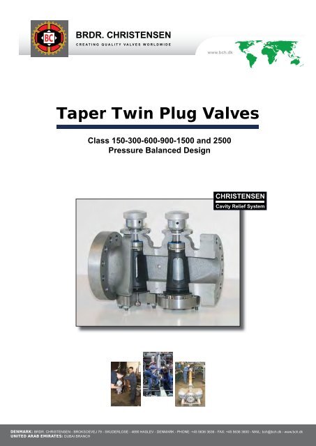
Taper Twin Plug Valves - Brdr. Christensen
Taper Twin Plug Valves - Brdr. Christensen
Taper Twin Plug Valves - Brdr. Christensen

You also want an ePaper? Increase the reach of your titles
YUMPU automatically turns print PDFs into web optimized ePapers that Google loves.
BC<br />
BRDR. CHRISTENSEN<br />
CREATING QUALITY VALVES WORLDWIDE<br />
www.bch.dk<br />
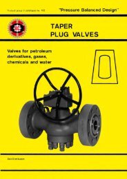
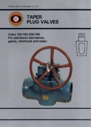
<strong>Taper</strong> <strong>Twin</strong> <strong>Plug</strong> <strong>Valves</strong><br />
Class 150-300-600-900-1500 and 2500<br />
Pressure Balanced Design<br />
CHRISTENSEN<br />
Cavity Relief System<br />
DENMARK: BRDR. CHRISTENSEN - BROKSOEVEJ 79 - SKUDERLOSE - 4690 HASLEV - DENMARK - PHONE: +45 5636 3636 - FAX: +45 5636 3600 - MAIL: bch@bch.dk - www.bch.dk<br />
UNITED ARAB EMIRATES: DUBAI BRANCH
BC<br />
BRDR. CHRISTENSEN<br />
CREATING QUALITY VALVES WORLDWIDE<br />
www.bch.dk<br />
<strong>Brdr</strong>. <strong>Christensen</strong> is a private owned company, which started the business<br />
adventure in 1942, and since 1958 the company has been manufacturer of quality<br />
plug valves worldwide. The company mission is by using employees with the very<br />
highest technical valve competences we will create the best dialog to succeed<br />
designing and manufacturing quality valves for the global oil and gas industry.<br />
Foundry, pattern and Machine shop in Denmark<br />
10.000 kg of metal being<br />
poured<br />
16” class 600 twin plug pattern<br />
S.2
BC<br />
BRDR. CHRISTENSEN<br />
CREATING QUALITY VALVES WORLDWIDE<br />
www.bch.dk<br />
The <strong>Christensen</strong> lubricanted taper plug valves are ideal shut of valves for almost<br />
any medium, especially under the most severe operating conditions. The pressure<br />
balanced design means that the plug is provided with pressure balance holes,<br />
which ensure that the plug is always in axial balance and consequently prevents<br />
the plug from taper locking<br />
The twin <strong>Plug</strong> <strong>Valves</strong> – Or Double Block and Bleed – were developed in 1993 as a<br />
result of several major oil companies expressing a increasing need for a verifi able<br />
double isolation plugvalve, fully complying with both ASME and API codes. The<br />
idea was to design a double plug in one body house, with the same face to face<br />
dimensions as the single valves have. The valves were to be used in high explosive<br />
area’s where verifi able double isolation valves are required.<br />
Today <strong>Christensen</strong> has supplied several thousand double block and bleed valves<br />
in sizes from 1” to 24” in the Classes 150 to 2500. The valves are working under<br />
extreme conditions from Alaska to the North Sea and from South America to the<br />
Middle East area.<br />
S.3
BC<br />
BRDR. CHRISTENSEN<br />
CREATING QUALITY VALVES WORLDWIDE<br />
Straightway<strong>Taper</strong> twin plug valves<br />
When we designed the new twinplug we developed a new feature, which no<br />
other valves had –we call it the CCR System.<br />
The CCR System is patented and is a special designed bore, going from the<br />
body sealing surface against the diaphragm, to the post outside of each plug.<br />
CHRISTENSEN<br />
Cavity Relief System<br />
The CCR System avoids overpressure in the cavity between the two plugs, if<br />
an emergency situation should occur – if the cavity pressure should increase –<br />
due to an explosion, fi re ect. The Pressure against the bottom cover will cause<br />
the studs to stretch and then open up for relief back into the feed pipeline, and<br />
no dangerous gasses/mediums will escape out into the atmosphere. When the<br />
pressure falls again the studs retract the bottom cover back to normal position,<br />
which closes the bore.<br />
S.4
BC<br />
BRDR. CHRISTENSEN<br />
CREATING QUALITY VALVES WORLDWIDE<br />
Contents<br />
Page<br />
Technical information – Section A<br />
The Design of the <strong>Twin</strong> plug A 6<br />
<strong>Twin</strong> <strong>Plug</strong> Pattern A 8<br />
<strong>Christensen</strong> Code System A 9<br />
<strong>Christensen</strong> Code System A 10<br />
Materials of Construction A 11<br />
List of standards and colour code A 12<br />
Operation A 13<br />
Method of operation A 14<br />
Wrenches A 15<br />
Valve connections A 16<br />
BCH Standard valve data sheet A 17<br />
Threaded holes in main connection Flanges A 18<br />
Valve identification – Section B<br />
Class 150, Operation by Wrench<br />
Actuator ISO top Flange or manuel gear box B 19/20<br />
Class 300, Operation by Wrench<br />
Actuator ISO top Flange or manuel gear box B 21/22<br />
Class 600, Operation by Wrench<br />
Actuator ISO top Flange or manuel gear box B 23/24<br />
Class 900, Operation by Wrench<br />
Actuator ISO top Flange or manuel gear box B 25/26<br />
Class 1500, Operation by Wrench<br />
Actuator ISO top Flange or manuel gear box B 27/28<br />
Class 2500, Operation by Wrench<br />
Actuator ISO top Flange or manuel gear box B 29/30<br />
Topwork Actuator Flange Acc. to ISO 5211 B 31/32<br />
Maintenance/Operation/Testing<br />
Valve characteristic – Section C<br />
Valve lubrication C 33<br />
Maintenance/Operations instructions C 34<br />
Maintenance/Operations instructions C 35<br />
Sealing compoud recommendation C 36<br />
Quality control C 37<br />
Pressure Test/Inspection C 38<br />
Weight, Torque and CV valves C 39<br />
<strong>Twin</strong> plug valve fact sheet C 40<br />
S.5
BC<br />
BRDR. CHRISTENSEN<br />
CREATING QUALITY VALVES WORLDWIDE<br />
STRAIGHTWAY<br />
TAPER TWIN PLUG VALVES<br />
18<br />
17<br />
70 15<br />
26<br />
27<br />
16<br />
28<br />
22<br />
25<br />
14 13 13a 12 11<br />
6<br />
2<br />
4<br />
41<br />
8<br />
29<br />
Lubrication points on both valvebodies<br />
24 21 5<br />
Straightw ay <strong>Taper</strong> tw in plug valves<br />
9<br />
Straightway<strong>Taper</strong> twin plug valves<br />
7<br />
The Part No.: design of the twin plug<br />
2. Stembearing<br />
Part 4. Sealing No.: Ring<br />
2. 5. Stembearing Gasket<br />
4. 6. Sealing Thrust Ring Plate<br />
5.<br />
7.<br />
Gasket<br />
Body<br />
6.<br />
8.<br />
Thrust<br />
Distance<br />
Plate<br />
Piece<br />
7. Body<br />
9. Bottom Cover<br />
8. Distance Piece<br />
11. Pressure Screw<br />
9. Bottom Cover<br />
12. Bottom Screw<br />
11. Pressure Screw<br />
12.<br />
13.<br />
Bottom<br />
Nut<br />
Screw<br />
13.<br />
13a.<br />
Nut<br />
Stud<br />
13a. 14. Stud Retaining Ring<br />
14. 15. Retaining Diaphragm Ring<br />
15. 16. Diaphragm <strong>Plug</strong><br />
16. 17. <strong>Plug</strong> Equalizer Ring<br />
17. 18. Equalizer Operating Ring Stem<br />
18. 21. Operating Check Valve Stem<br />
21. 22. Check Parallel Valve Key<br />
22. 24. Parallel Lubricant Key Screw<br />
24. 25. Lubricant Snap Ring Screw<br />
25. 26. Snap Spring Ring<br />
26. 27. Spring Ball<br />
27. 28. Ball Diaphragm<br />
28. 29. Diaphragm Gearbox<br />
29. 41. Gearbox Fire Seal<br />
41. 70. Fire Sealing Ring<br />
70. Sealing Ring<br />
The <strong>Christensen</strong> lubricated twin plug valve is designed for use in critical applications where, verifiable tight<br />
shutoff is demanded. The design of the <strong>Twin</strong> <strong>Plug</strong> Valve is very compact, space and weight is minimized.<br />
Futhermore, the design has far less possible leak paths compared to the conventional Double Block & Bleed<br />
Valve assemblies. In most sizes and pressure classes, the face to face dimensions of this valve are the<br />
same as for a single plug valve or ball valve.<br />
Since the only moving parts are the plug and the stem, the basic operation of the valve is very simple. When<br />
the plug is turned 90°, the valve moves from closed to open position – and vice versa.<br />
The plug is tapered 1:6 and is individually fitted to the valve body with very close tolerances. It incorporates<br />
Metal to Metal sealing, which means that no soft seal will be damaged by the flowing medium.<br />
As a secondary seal, the valve is provided with a lubrication system which allows feeding a special lubricant<br />
into the valve while the valve is in operation.<br />
Besides, sealing, the purpose of the lubricant is to protect the internals of the valve against corrosion and<br />
wear as well as reducing the valve torque.<br />
The valve is manufactured in a “Pressure Balanced Design”, this means that the plug is provided with<br />
pressure balance holes, which ensure that the plug is always in axial balance and consequently prevents the<br />
plug from taper locking. Futhermore, in order to reduce the valve torque, the surface of the plug is coated<br />
with P.T.F.E. Film.<br />
The plug and the operating stem are two separate parts, which are connected by means of an equalizer ring<br />
acting as a universal joint. The stem is Blowout-proof. This means the only way to remove it is from the<br />
bottom after the valve is disassembled.<br />
A.6<br />
A 6
BC<br />
BRDR. CHRISTENSEN<br />
CREATING QUALITY VALVES WORLDWIDE<br />
The design of the twin plug<br />
With three independent seeals the stem sealing of the <strong>Christensen</strong> valve is unique. This is made up<br />
of a reinforced P.T.F.E. Thrust plate (6) followed by a 100% pure graphite seal with a stainless steel<br />
back.up ring (41). The graphite seal is very efficient at extremely high temperatures, and meets the<br />
most strict demands of several different standards relative to fire safe design. At the top of the stem,<br />
the primary seal (sealing ring) is placed (4). The sealing ring is P.T.F.E. (teflon) with a special alloy<br />
spring. The ring can be replaced from the outside. The sealing ring is kept in a place by the stem<br />
bearing (2) and the snap ring/locking ring (25)<br />
In addition to the stem seals mentioned, the wrench operated valve has a weatherproof seal to prevent<br />
penetration of water and dirt into the stem.<br />
The bottom cover (9) is bolted on the valve body, with the studs (13a) and the nuts (13). Two flexible<br />
plates of diaphragms (15) and (28) are placed in a recess between the valve body and the bottom<br />
cover. They operate as a metal seal between the valve body and the bottom cover in order to prevent<br />
the medium from leaking at the adjustment arrangement pressure screw (11), the retaining ring<br />
(14) and the bottom screw (12).<br />
The CCR System (<strong>Christensen</strong> Cavity Relief System)<br />
A new feature has been added to protect against possible overpressure in the inner cavities (between,<br />
in and below the two plugs), this feature is a patented pressure relief bore. This feature is a<br />
bore going from the body sealing surface against the diaphragm, to the port outside of each plug.<br />
While operating normally, the bore is kept closed by the pressure of the bottom cover, obtained by<br />
studs and nuts, against the diaphragms.<br />
If an overpressure occurs, while both plugs are in the closed position, e.g. if the valve is exposed to<br />
thermal stress, the pressure againt the bottom cover will vause the studs to stretch and then open<br />
the relief, so the pressure escapes into the pipeline, and not out in the atmosphere. As the pressure<br />
falls the studs retract the bottom cover back into place and close the bore.<br />
Besides the metal to metal sealing between body and bottom cover a pure graphite sealing ring (70)<br />
is installed.<br />
A bleed port is available in configuration as per customer preference. This port allows access to<br />
verify the sealing of the valve itself. Any leakage past the first plug would be detected via the bleed<br />
port.<br />
The plug adjustment within the valve body means of a pressure screw (11) and is kept in place by<br />
the retaining ring (14) when the bottom screw (12) is tightened. All adjustments to the plug are accomplised<br />
by a “flexing” of the two diaphragms.<br />
As mentioned, the valve is provided with a lubrication system which allows penetration of special<br />
lubricant into the valve though lubricant screws (24) and check valves (21). The lubricant is injected<br />
into a network of grooves by means of a special high pressure lubricant gun. This network system<br />
ensures that all seal faces are supplied with a thin coat of lubricant which acts as a secondary seal.<br />
The valve can be supplied as wrench operated or gear operated. On the gear operated valve the<br />
gear can be rotated 180° if needed.<br />
Moreover, the <strong>Twin</strong> <strong>Plug</strong> valve is designed with ISO top as standard, which allow mounting of any<br />
kind of actuator. The <strong>Christensen</strong> <strong>Twin</strong> <strong>Plug</strong> is fully bidirectional and can be mounted in any position<br />
including upside down. Locking devices, sequential locking devices etc. are all avaliable upon<br />
request.<br />
A.7
BC<br />
BRDR. CHRISTENSEN<br />
CREATING QUALITY VALVES WORLDWIDE<br />
<strong>Twin</strong> plug pattern<br />
<strong>Twin</strong> <strong>Plug</strong> Pattern<br />
All <strong>Christensen</strong> <strong>Twin</strong> <strong>Plug</strong> <strong>Valves</strong> are designed to keep flow transitions to a minimum. The in line<br />
design gives maximum port areas with minimal flow profile changes. This results in Cv rates among<br />
the highest in the industry.<br />
The design has only one recovery nozzle (outlet of 2nd plug). The flow rates of the<br />
<strong>Brdr</strong>. <strong>Christensen</strong> <strong>Twin</strong> <strong>Plug</strong> <strong>Valves</strong> are quite high and result in less pressure drop than witnessed<br />
with two separate single plug valves of equal size. The valve is bidirectional.<br />
A.8
BC<br />
BRDR. CHRISTENSEN<br />
CREATING QUALITY VALVES WORLDWIDE<br />
<strong>Christensen</strong> code system<br />
This catalogue covers <strong>Twin</strong> <strong>Plug</strong> <strong>Valves</strong> in the taper plug design to the ASME pressure class 150 –<br />
300 – 600 – 900 – 1500 and 2500.<br />
For information on valve types not covered by this catalogue, please contact our sole agent/representative<br />
in your country.<br />
To identify the corret types of valve, please use the fi gure number key on the following page, by<br />
means of which the valve fi gure number is specifi ed in the shape of letters and digits.<br />
Additional to the fi gure number, quantify and size, please state the following information:<br />
- Application<br />
- Range of temperature<br />
- Normal working pressure<br />
- Type of fl anges (raised face/ring joint or other)<br />
- Dimension of pipe (only when valves have butt or socket weiding ends)<br />
- Accessories, if any<br />
A.9
BC<br />
BRDR. CHRISTENSEN<br />
CREATING QUALITY VALVES WORLDWIDE<br />
<strong>Christensen</strong> Code system<br />
A telling code system<br />
Create the number key for <strong>Twin</strong> <strong>Plug</strong> Valve<br />
1 2 3 4 5 6 7 8 9 10 11<br />
Product group <strong>Twin</strong>Valve (tapered plug) “Pressure Balanced Design 55<br />
Standard<br />
American API 6A<br />
American (API 6D, API 599, ect.)<br />
- AE<br />
- AP<br />
Materials in body<br />
Ductile Iron<br />
Cast Iron<br />
Cast Steel<br />
Stainless Steel<br />
Special Allow Steel (To order)<br />
2<br />
4<br />
7<br />
8<br />
9<br />
Port<br />
Straightway, rectangular<br />
Straightway, round<br />
0<br />
1<br />
Connection<br />
Screwed Ends<br />
Flanged Ends<br />
Clamps Hubs<br />
Welding Ends<br />
Socket Welding Ends<br />
0<br />
1<br />
4<br />
5<br />
6<br />
Pressure stage Class 125<br />
Class 150 (PN 20)<br />
Class 250<br />
Class 300 (PN 50)<br />
Class 400 (PN 64)<br />
Class 600 (PN 100)<br />
Class 900 (PN 150<br />
Class 1500 (PN 250)<br />
Class 2500 (PN 420)<br />
1<br />
2<br />
3<br />
4<br />
5<br />
6<br />
7<br />
8<br />
9<br />
Materials in plug<br />
Ductile Iron<br />
Cast Iron<br />
Steel<br />
Steel Stainless Steel<br />
Special Alloy Steel (To order)<br />
2<br />
4<br />
7<br />
8<br />
9<br />
Methods of<br />
operation<br />
Wrench on both valves<br />
Wrench on left valve and gear with vertical handwheel on<br />
right valve<br />
Wrench on right valve and gear with vertical handwheel<br />
on left valve<br />
Wrench on left valve and bare stem and flange for<br />
actuator on right valve<br />
Wrench on right valve and bare stem and flange for<br />
actuator on left valve<br />
Gear with vertical handwheel on both valves<br />
Gear with horizontal handwheel on both valves<br />
Gear wih vertical handwheel on left valve and gear with<br />
horizontal handwheel on right valve<br />
Gear with vertical handwheel on right valve and gear with<br />
horizontal handwheel on left valve<br />
Gear with vertical handwheel on left valve and bare stem<br />
and flange for actuator on right valve<br />
Gear with vertical handwheel on right valve and bare<br />
stem and flange for actuator on left valve<br />
Gear with horizontal handwheel on left valve and bare<br />
stem and flange for actuator on right valve<br />
Gear with horizontal handwheel on right valve and bare<br />
stem and flange for actuator on left valve<br />
Bare stem and flange for actuator on both valves<br />
NN<br />
NC<br />
CN<br />
NL<br />
LN<br />
CC<br />
DD<br />
CD<br />
DC<br />
CL<br />
LC<br />
DL<br />
LD<br />
LL<br />
Size of bleed<br />
See page A 17<br />
½“<br />
¾“<br />
1”<br />
1½”<br />
2”<br />
2½“<br />
3”<br />
The customer specification<br />
- 15<br />
- 20<br />
- 25<br />
- 40<br />
- 50<br />
- 65<br />
- 80<br />
- 90<br />
Location of bleed<br />
Frontside/operatingside<br />
Backside/the opposite side of operatingside<br />
F<br />
B<br />
Bleed connection<br />
A.10<br />
A 10<br />
Screwed end<br />
Flanged End<br />
Intergal- Block Flange incl. Stud bolt<br />
Clamps End<br />
Welding End<br />
Socket Welding End<br />
Other ends (special end)<br />
Example: 55-AP 70199 CL-25F1<br />
0<br />
1<br />
2<br />
4<br />
5<br />
6<br />
9
BC<br />
BRDR. CHRISTENSEN<br />
CREATING QUALITY VALVES WORLDWIDE<br />
Materials of construction<br />
CAST IRON<br />
CAST IRON<br />
ASTM A 126 Class B (High strength grey iron).<br />
Tensile Strength: min. 31000 PSI (214 N/mm2).<br />
Cast Iron material is very economical and suitable for most commom servise conditions such as air, water, gas and oil<br />
at medium pressure and temperatures. It possesses good resistance to corrosion in most organic solutions, alkalies<br />
and many acids of higher concentrations at normal temperatures. <strong>Plug</strong>s are anti-friction treated with P.T.F.E.<br />
DUCTILE IRON (Cast Iron with spheroidal Graphite).<br />
ASTM A 536 Gr. 60-40-18.<br />
Tensile Strength: min. 60000 PSI (414 N/mm2)<br />
This material is especially used where cast iron does not fulfil the requirements and where cast steel is to expensive.<br />
<strong>Plug</strong>s are anti-friction treated with P.T.F.E.<br />
CARBON STEEL<br />
ASTM A 216 Grade WCB.<br />
Tensile Strength: min. 70000 PSI (485 N/mm2).<br />
PR valves of cast steel are made in accordance with the specification of the mentioned ASTM standard. To counteract<br />
seizing steel plugs have a thin coat 20 um (special tegn, se PDF) of electroless nickel, and then anti-friction treated<br />
with P.T.F.E. Carbon steel is suited for valves in cold or hot water applications without corrosive impurities. It is also<br />
suitable for oil, gas, air and other line fluids where valves are required of high strength, toughness and stability against<br />
vibration, blows and fire, except for extremely high or low temperatures which require steel alloys.<br />
The valves are also available to NACE Standard MR-01-75. Hardness level of Rc 22 or lower.<br />
LEAD-BRONZE 80/10/10<br />
CuPb10Sn10. ISO 1338 – ASTM B30 937.<br />
Tensile Strength: min. 12500 PSI (180 N/mm2).<br />
Brinell hardness: 65<br />
Chemical Properties: Resistant to actions of ordinary services.<br />
Physical Properties: Good pressure tightness and resistant to wear.<br />
Other alloys, fx. 90/10 or 88/10/2,0 are delivered on inquiry.<br />
STAINLESS ACID-RESISTING STEEL<br />
Rust and acid resisting<br />
Chromium Nickel Molybdenum<br />
Cr 18% to 21% 9 to 12% 2 to 3<br />
ASTM A 351 Grade CF8M or AISI 316.<br />
Tensile Strength: min. 70000 PSI (485 N/mm2).<br />
To counteract seizing plugs in stainless steel have a thin coat 20 (special tegn, se PDF) electroless nickel, and then<br />
anti-friction treated with P.T.F.E.<br />
AUSTENITIC – FERRITIC STEEL (Duplex stainless steel)<br />
ASTM A 890 4A,<br />
Chromium Nickel Molybdenum Nitrogen<br />
Cr 22% Ni 5% Mo 2,5% N 0,1%<br />
Tensile strength: min. 620 N/mm2<br />
The materials A 890 4A are austenitic-ferritic acid-resistant steel with very high mechanical properties. Moreover they<br />
are extremely, resistant to corrosion.<br />
The materials A 980 4A are very resistant to stress – (SCC) and pitting corrosion in enviroments containing chloride.<br />
The resistance to stress corrosion (SCC) caused by hydrogen sulphide in enviroments containing chloride is also<br />
excellent. The materials A 890 4A meet the demands usually requiring high alloyed nickel qualities. As the content of<br />
crominin and nickel is fairly low there materials will prove an economically good alternative to more expensive high<br />
alloyed qualities. To counteract seizing plugs in stainless steel have a thin coat 20 (special tegn, se PDF) electroless<br />
nickel, and then anti-friction treated with P.T.F.E.<br />
SPECIAL QUALITIES AND ALLOYS:<br />
Test, which exceeds the requirements of the respective standards, can be carried out on the above mentioned<br />
materials if required.<br />
Special alloys are manufactured on request, ect. Super Duplex.<br />
A.11
BC<br />
BRDR. CHRISTENSEN<br />
CREATING QUALITY VALVES WORLDWIDE<br />
List of standards and colour code<br />
COLOUR CODE<br />
To facilitate identification BCH <strong>Valves</strong> are normally painted as follows:<br />
Cast Iron: Green Steel: Blue Stainless Steel: Silver Grey<br />
Ductile: Dark Grey Bronze: Unpainted Duplex: Light Grey<br />
List of standards<br />
List of standards<br />
The Standards printed bold in bold print print is to is be to considered be considered as the as main the standard main standard (specification). (specification). The below The<br />
stardards below stardards in thin originate in thin from originate the main from stanard. the main Each stanard. main standard Each main has its standard own reference. has its own reference.<br />
The list list of of standard pratice pratice is only is only intended intended as a as guide. a guide.<br />
BS 5353<br />
BS 1560<br />
BS 4504<br />
BS 21<br />
BS 2080<br />
BS 6755<br />
ASME B 16.34<br />
ASME B 15.6<br />
ASME B 16.11<br />
ASME B 16.25<br />
ASME B 1.20.1<br />
ASME B 16.10<br />
API 6D<br />
ASME B 16.5<br />
ASME B 31.4<br />
ASME B 31.8<br />
API 599<br />
API 598<br />
ASME B 16.5<br />
ASME B 16.25<br />
ASME B 16.10<br />
ASME B 16.34<br />
API 6A<br />
Quality management system<br />
List of Standard Practice<br />
Specification for steel plug valves<br />
Circular Flange for Pipes, <strong>Valves</strong> and Fittings (Class designated)<br />
Circular Flange for Pipes, <strong>Valves</strong> and Fitting (PN designated)<br />
Pipe Threads<br />
Face-to-Fae, Centre-to-Face, End-to-End and Centre-to-End dimensions of<br />
valves<br />
Testing of Valve Part 1 Specification for production pressure testing<br />
requirements.<br />
<strong>Valves</strong> – Flanged, Threaded and Welding Ends<br />
Pipe Flanges and Flanged Fittings<br />
Forged Fittings, Socket-Welding and Threaded Ends<br />
Buttwelding Ends<br />
Pipe Threads, General Purpose (Inch)<br />
Face-to-Face and End-to-End dimensions of <strong>Valves</strong><br />
Specification for Pipeline <strong>Valves</strong> (Gate, <strong>Plug</strong>, Ball and Check <strong>Valves</strong>)<br />
Pipe Flanges and Flanged Fittings<br />
Liquid Petroleum Transportation Piping Systems<br />
Gas Transmission and Distribution Piping Systems<br />
Metal <strong>Plug</strong> <strong>Valves</strong> – Flanged and Welding Ends<br />
Valve Inspection and Test<br />
Pipe Flanges and Flanged Fittings<br />
Buttwelding Ends<br />
Face-to-Face and End-to-End Dimensions of <strong>Valves</strong><br />
<strong>Valves</strong> – Flanged, Threaded and Welding Ends<br />
Specification for Wellhead and Christman Tree Equipment.<br />
Design and manufacture of valves for liquid and gaseous applications on<br />
onshore and offshore installation in acc. to Pressure Equipment, Directive<br />
97/23/EC<br />
Design and manufacture of valves and associated pipe fittings ISO 9001<br />
NACE MR0175<br />
American Petroleum institute 6A<br />
American Petroleum institute 6D<br />
Strandard Material Requirements Sulfide Stress Cracking Resistant – Metallic.<br />
Materials for Oilfield Equipment.<br />
API 607<br />
The NACE MR01-75 standard can be connected to every main standard (printed<br />
with bold) provided that the choise of material is acceptable to the NACE MR01-<br />
75 standard<br />
Fire Test for Soft-Seated Ball <strong>Valves</strong><br />
A.12
BC<br />
BRDR. CHRISTENSEN<br />
CREATING QUALITY VALVES WORLDWIDE<br />
Operation<br />
The simplest method of operating the valve is by using a<br />
wrench directly on top of the valve plug.<br />
Straightway valves open and close by rotating through 90°.<br />
The wrench can be fi tted on the square of the valve plug in eight<br />
different postitions. This is a big advantage in places with limited<br />
space.<br />
Wrench operation is used on relatively small valve sizes, as<br />
indicated on the dimension sheets.<br />
Gear, type C, is enclosed in water-proof casing, with the handwheel<br />
located vertically on side of the valve. Worm and worm<br />
wheel are embedded in heavy bronze bearings, and the axial<br />
load stress is absorbed by ball bearings. Both bearings<br />
and tooth racks are lubricated with concentrated molybdenum<br />
grease to resist high temperatures. (See lubrication of<br />
gear, page C4)<br />
The wrench is available in a short and a long<br />
version as type 8K and type 8L.<br />
Gear, type C, is available in all pressure classes and valve sizes,<br />
as indicated on the dimension sheets. Type C can be fi tted with<br />
electric, pneumatic or hydraulic actuator.<br />
The connection between valve and gear are ISO type.<br />
Gear, type D, is enclosed in water-proof casing, with the handwheel<br />
located horizontally on top of the valve. Worm and worm<br />
wheel are embedded in heavy bronze bearings, and the axial<br />
load stress is absorbed by ball bearings. Both bearings<br />
and tooth racks are lubricated with concentrated molybdenum<br />
grease to resist high temperatures (See lubrication of gear, page<br />
C4).<br />
The gear has fi xed stops at extreme position,<br />
plus position indicator<br />
Gear, type D, is available in pressure classes and valve sizes, as<br />
indicated on the dimension sheet. Type D can be fi tted with<br />
electric, pneumatic and hydraulic actuator. The connection<br />
between valve andgear are a ISO type.<br />
Gear, type D, is available in pressure classes and valve sizes,<br />
as indicated on the dimension sheet. Type D can be fi tted with<br />
electric, pneumatic and hydraulic actuator.<br />
The connection between valve and gear are a ISO type.<br />
A.13
BC<br />
BRDR. CHRISTENSEN<br />
CREATING QUALITY VALVES WORLDWIDE<br />
Method of operation<br />
METHOD OF OPERATION<br />
<strong>Brdr</strong>. <strong>Christensen</strong> <strong>Twin</strong> <strong>Plug</strong> <strong>Valves</strong> are available in a number of possible modes<br />
1) Both plugs wrench operated<br />
2) One plug wrench, one plug gear operated<br />
3) Both plugs gear operated<br />
4) Pneumatic, Hydraulic and Electric Actuation on one or both plugs<br />
In addition to the above gearboxes are available in several configurations as well<br />
A) Vertical handwheel operation<br />
B) Horizontal handwheel operations<br />
C) Offset Horizontal Handwheel operation<br />
D) Offset Horizontal Handwheel operation<br />
E) Handwheel operation from either side of valve or from the same side of valve<br />
This variety of configurations insures that out design usually fits into the tightest of available<br />
spaces.<br />
Customer must advise which above configuration is preferred. Standard configuration is two<br />
vertical handwheel when gearboxes are required.<br />
A.14
BC<br />
TAPER TWIN PLUG VALVES<br />
STRAIGHTWAY<br />
TAPER TWIN PLUG VALVES<br />
BRDR. CHRISTENSEN<br />
CREATING QUALITY VALVES WORLDWIDE<br />
Wrenches<br />
Wrenches<br />
Wrenches<br />
Standard wrench type 8K (Short)<br />
STRAIGHTWAY<br />
TAPER TWIN PLUG VALVES<br />
Wrenches<br />
Standard wrench type 8K (Short)<br />
Standard wrench type 2K (Short)<br />
Standard wrench type 2K (Short)<br />
Standard wrench type 8K (Short)<br />
Wrench type 8L (Long)<br />
A B C D<br />
17 14 140 20<br />
19 16 150 22<br />
24 18 200 26<br />
Standard wrench 27 type 2K (Short)<br />
20 225 30<br />
30 22 280 33<br />
36 26 330 38<br />
50 40 420 52<br />
55 45 815 58<br />
65 50 940 70<br />
70<br />
A<br />
50<br />
B<br />
1090<br />
C<br />
76<br />
D<br />
17 14 140 20<br />
19 16 150 22<br />
Wrench type 8L (Long)<br />
24 18 200 26<br />
27 20 225 30<br />
30 22 280 33<br />
36 26 330 38<br />
50 40 420 52<br />
55 A 45 B 815 C 58 D<br />
65 17 50 14 230 940 70 20<br />
70 22 50 20 1090 300 76 30<br />
24 20 300 30<br />
Wrench type 8L 27 (Long)<br />
20 340 30<br />
30 26 420 38<br />
36 26 470 42<br />
41 35 650 50<br />
50 45 815 58<br />
55 A 50 B 1090 C 70 D<br />
17 65 14 50 1270 230 20 80<br />
22 20 300 30<br />
24 20 300 30<br />
27 20 340 30<br />
15<br />
30 26 420 38<br />
36 26 470 42<br />
41 35 650 50<br />
50 45 815 58<br />
55 50 1090 70<br />
65 50 1270 80<br />
A15<br />
A15<br />
15<br />
A15<br />
A.15
BC<br />
BRDR. CHRISTENSEN<br />
CREATING QUALITY VALVES WORLDWIDE<br />
Valve Connections<br />
STRAIGHTWAY<br />
TAPER TWIN PLUG VALVES<br />
Connections<br />
Screwed Ends:<br />
Designed in accordance with API Line<br />
Pipe threads (<strong>Taper</strong>) API Std. 5B<br />
Table 2.1 or ASME Std. B1.20.1.<br />
Available in size ½” to 4”<br />
Flanges RF:<br />
Designed in accordance with the ASME B16.5 Standard,<br />
except that two or four of the bolt holes at the lower part of<br />
the flange are threaded. See the dimensions page B1.<br />
Flanges RJ:<br />
Designed in accordance with the ASME B16.5 Standard,<br />
except that two or four of the bolt holes at the lower part of<br />
the flange are threaded. See the dimensions page B1.<br />
Clamps/hubs:<br />
Designed in accordance with the customer specified<br />
clamps type (For instance grayloc, spo lock, destec,<br />
techlok etc.)<br />
A.16<br />
A16
BC<br />
BRDR. CHRISTENSEN<br />
CREATING QUALITY VALVES WORLDWIDE<br />
BCH standard valve data sheet<br />
Bleeds and sizes<br />
Bleeds and sizes<br />
BCH standard valve data sheet<br />
Code<br />
Standard operation:<br />
Smaller valves have square heads for wrench operation on<br />
both valves.<br />
Lager valve have gear operation with Vertical handwheel on<br />
both valves.<br />
The front of the valve is the operatingside.<br />
Standard size of bleed<br />
connection: Valve: DN 1” Bleed: ½”<br />
Valve: DN 2” Bleed: ½”<br />
Valve: DN 3” Bleed: ½”<br />
Valve: DN 4” Bleed: ¾”<br />
Valve: DN 6” Bleed: ¾”<br />
Valve: DN 8” Bleed: 1”<br />
Valve: DN 10” Bleed: 1”<br />
Valve: DN 12” Bleed: 1”<br />
Valve: DN 14” Bleed: 1½”<br />
Valve: DN 16” Bleed: 1½”<br />
Valve: DN 18” Bleed: 2”<br />
Valve: DN 20” Bleed: 2”<br />
Valve: DN 24” Bleed: 2”<br />
Bleed: 2½”<br />
Bleed: 3”<br />
Standard location of bleed: On the valve backside = the opposite of operatingside.<br />
Valve < DN 4” have always lubrication point on the opposite<br />
side of the bleed<br />
NN<br />
CC<br />
15<br />
15<br />
15<br />
20<br />
20<br />
25<br />
25<br />
25<br />
40<br />
40<br />
50<br />
50<br />
50<br />
65<br />
80<br />
B<br />
Frontside/operationside<br />
F<br />
Standard bleed connection: Screwed (inside thread API) Valve size < 12” 0<br />
Flanged RF Valve size > 14” 1<br />
NB. When requirement are different from the BCH standard, please advice at inquiry or<br />
order stage.<br />
A.17
BC<br />
BRDR. CHRISTENSEN<br />
CREATING QUALITY VALVES WORLDWIDE<br />
STRAIGHTWAY<br />
TAPER TWIN PLUG VALVES<br />
Threaded holes in main<br />
connection Threaded flanges holes in main<br />
connection flanges<br />
In each connection flange<br />
Valve size Class 150 Class 300 Class 600<br />
DN A B C A B C A B C<br />
1” 1/2” UNC 2 of 4 15 mm 5/8” UNC 2 of 4 19 mm 5/8” UNC 2 of 4 19 mm<br />
1½” ¾” UNC 4 of 4 20 mm<br />
2” 5/8” UNC 2 of 4 15 mm 5/8” UNC 2 of 8 19 mm 5/8” UNC 2 of 8 19 mm<br />
3” 5/8” UNC 2 of 4 19 mm 3/4” UNC 2 of 8 22 mm 3/4” UNC 2 of 8 22 mm<br />
4” No threaded holes No threaded holes 7/8” UNC 2 of 8 25 mm<br />
6” 3/4” UNC 2 of 8 22 mm 3/4” UNC 2 of 12 22 mm 1” UNC 4 of 12 30 mm<br />
8” 3/4” UNC 2 of 8 22 mm 7/8” UNC 2 of 12 25 mm 1 1/8” 8UN 4 of 12 30 mm<br />
10” 7/8 UNC 2 of 12 25 mm 1” UNC 4 of 16 30 mm 1 1/4” 8UN 4 of 20 38 mm<br />
12” 2 of 12 25 mm 1 1/8” 8UN 2 of 16 30 mm 1 1/4” 8UN 4 of 20 38 mm<br />
14” 1 1/8” 8UN 4 of 20 30 mm 1 3/8” 8UN 4 of 20 42 mm<br />
16” 1” UNC 2 of 16 30 mm 1 ¼” 8UN 4 of 20 38 mm 1 1/2” 8UN 4 of 20 46 mm<br />
18” 1 1/8” 8UN 2 of 16 29 mm 1 ¼” 8UN 2 of 24 32 mm 1 5/8” 8UN 4 of 20 49 mm<br />
20” 1 ¼” 8UN 4 of 24 38 mm 1 5/8” 8UN 4 of 24 49 mm<br />
24” 1½” 8UN 4 of 24 40 mm 1 7/8” 8UN 6 of 24 56 mm<br />
In each connection flange<br />
Valve size Class 900 Class 1500 Class 2500<br />
DN A B C A B C A B C<br />
1” 7/8” UNC 4 of 4 25 mm 7/8” UNC 4 of 4 25 mm<br />
2” 7/8” UNC 2 of 8 25 mm 7/8” UNC 2 of 8 25 mm 1” UNC 2 33 mm<br />
3” 7/8” UNC 2 of 8 25 mm 1 1/8” 8NC 2 of 8 30 mm 1 1/4” 8UN 2 38 mm<br />
4” 1 1/8” 8UN 2 of 8 30 mm 1 1/4” 8NC 2 of 8 38 mm 1 1/2” 8UN 2 46 mm<br />
6” 1 1/8” 8UN 2 of 12 30 mm 1 3/8” 8NC 4 of 12 42 mm 2” 8UN 2 61 mm<br />
8” 1 3/8” 8UN 2 of 12 42 mm 1 5/8” 8NC 2 of 12 49 mm 2” 8UN 4 61 mm<br />
10” 1 3/8” 8UN 4 of 16 42 mm 1 7/8” 8NC 2 of 12 57 mm 2 1/2” 8UN 4 76 mm<br />
A18<br />
12” 1 3/8” 8UN 4 of 20 42 mm 2” 8UN 4* of 16 61 mm<br />
14” 1 1/2” 8UN 4 of 20 46 mm 2 1/4” 8UN 2 of 16 68 mm<br />
16” 1 5/8” 8UN 4 of 20 49 mm 2 1/2” 8UN 4 of 16 76 mm<br />
20” 2” 8UN 4 of 20 61 mm<br />
* + 2 threaded holes at the top of the valve<br />
A.18
BC<br />
BRDR. CHRISTENSEN<br />
CREATING QUALITY VALVES WORLDWIDE<br />
Cast steel class 150<br />
Rectangular port<br />
Cast steel class 150 rectangular port<br />
Class Max CWP Test Pressure Pattern Connections Port Materials<br />
150 285 Psi<br />
Shell 450 Psi<br />
Seat 515 Psi<br />
Straightway<br />
Flanges R.F or R.J.<br />
ASME B 16.5<br />
Face to Face<br />
See column V<br />
Bleed: See Data Sheet or<br />
specified by purchaser<br />
Rectangular<br />
Body & Cover<br />
Cast Steel<br />
ASTM A 216<br />
Grade WCB<br />
Cover:<br />
EN 10025-2<br />
S355J2<br />
<strong>Plug</strong><br />
Cast Iron<br />
ASTM A 126<br />
Class B<br />
Steel<br />
Operation:<br />
Manual by wrench.<br />
Type 8K.<br />
Operation:<br />
Bare stem with mounting flange for actuation.<br />
“ISO 5211”<br />
Operation:<br />
Manual worm gear with vertical handwheel.<br />
N<br />
R<br />
Q<br />
C<br />
B<br />
V<br />
A<br />
B<br />
R<br />
Q<br />
E<br />
V<br />
D<br />
D<br />
F<br />
A<br />
K<br />
D<br />
I1<br />
J<br />
I M A<br />
R<br />
Q<br />
B L<br />
V<br />
H<br />
<strong>Plug</strong> DN 1” – 6” DN 1” – 20” DN 1” – 4”<br />
Cast Iron 55-AP 70124 NN-XXXX 55-AP 70124 LL-XXXX 55-AP 70124 CC-XXXX<br />
Steel 55-AP 70127 NN-XXXX 55-AP 70127 LL-XXXX 55-AP 70127 CC-XXXX<br />
XXXX: See data sheet page 12 or code sheet page 5<br />
DN A B C D E F H I J K L M N Q R V V<br />
1” 52 88 138 100 89 30 300 124/209 32 40 130 132 50 25 108 229 229 F07<br />
2” 65 106 158 115 110 30 300 124/209 32 40 151 132 50 51 152 267 279 F07<br />
3” 80 142 190 165 131 36 300 124/209 32 40 172 132 50 76 191 343 355 F07<br />
4” 86 158 224 170 154 50 300 124/209 32 40 195 132 50 102 229 432 445 F10<br />
6” 116 213 282 232 215 55 152 279 546 558 F14<br />
8” 147 240 270 249 203 343 622 635 F14<br />
10” 150 266 296 277 254 406 661 674 F14<br />
12” 175 303 340 309 305 483 762 774 F16<br />
14” 202 334 380 351 337 533 889 902 F25<br />
16” 230 356 415 386 387 597 991 1004 F25<br />
18” 257 426 450 450 438 635 1092 1104 F30<br />
20” 284 471 494 503 489 699 1194 1209 F30<br />
Raised<br />
Face<br />
Ring<br />
Joint<br />
ISO<br />
Flange<br />
5211<br />
B 19<br />
B.19
I<br />
I<br />
I<br />
I<br />
I<br />
I<br />
BC<br />
BRDR. CHRISTENSEN<br />
CREATING QUALITY VALVES WORLDWIDE<br />
Cast steel class 150<br />
Rectangular port<br />
Cast steel class 150 rectangular port<br />
Class Max CWP Test Pressure Pattern Connections Port Materials<br />
150 285 Psi<br />
Shell 450 Psi<br />
Seat 315 Psi<br />
Straightway<br />
Flanges R.F or R.J.<br />
ASME B 16.5<br />
Face to Face<br />
See column V<br />
Bleed: See Data Sheet or<br />
specified by purchaser<br />
Rectangular<br />
Body & Cover<br />
Cast Steel<br />
ASTM A 216<br />
Grade WCB<br />
Cover:<br />
EN 10025-2<br />
S355 J2<br />
<strong>Plug</strong><br />
Cast Iron<br />
ASTM A 126<br />
Class B<br />
Steel<br />
Operation:<br />
Manual worm gear with vertical handwheel CC<br />
N<br />
Operation:<br />
Manual worm gear with horizontal handwheel DD<br />
H<br />
H<br />
Operation:<br />
Manual worm gear with one horizontal<br />
handwheel and one vertical handwheel DC<br />
H<br />
R<br />
Q<br />
V<br />
B L<br />
R<br />
Q<br />
P<br />
B<br />
P<br />
M<br />
R<br />
Q<br />
H<br />
J<br />
B L<br />
A<br />
D<br />
V<br />
D<br />
A<br />
J<br />
N<br />
V<br />
D<br />
O<br />
M<br />
A<br />
J<br />
N<br />
N<br />
H<br />
J<br />
O<br />
H<br />
<strong>Plug</strong> DN 6” – 20” DN 6” – 20” DN 6” – 20”<br />
Cast Iron 55-AP 70124 CC-XXXX 55-AP 70124 DD-XXXX 55-AP 70124 DC-XXXX<br />
Steel 55-AP 70127 CC-XXXX 55-AP 70127 DD-XXXX 55-AP 70127 DC-XXXX<br />
XXXX: See data sheet page 12 or code sheet page 5<br />
DN A B D H I J L M N O P Q R V V<br />
6” 116 213 232 400 101/201 38 314 205 85 46 374 152 279 546 558<br />
8” 147 240 270 400 101/201 38 350 205 85 46 409 203 343 622 635<br />
10” 150 266 296 400 101/201 38 378 205 85 46 438 254 406 661 674<br />
12” 175 303 340 600 101/201 38 420 230 95 70 479 305 483 762 774<br />
14” 202 334 380 600 101/201 38 506 298 135 69 577 337 533 889 902<br />
16” 230 356 415 600 101/201 38 541 298 135 69 612 387 597 991 1004<br />
18” 257 426 450 600 101/201 38 580 337 160 108 650 438 635 1092 1104<br />
20” 284 471 494 600 101/201 38 659 337 160 108 729 489 699 1194 1206<br />
Raised<br />
Face<br />
Ring<br />
Joint<br />
B.20 B 20
BC<br />
BRDR. CHRISTENSEN<br />
CREATING QUALITY VALVES WORLDWIDE<br />
Cast steel class 300<br />
Rectangular port<br />
Cast steel class 300 rectangular port<br />
Cast steel class 150 rectangular port<br />
Cast steel class 150 rectangular port<br />
Class Class Max Max CWP CWP Test Test Pressure Pressure Pattern Connections Port Materials<br />
Class Max CWP Test Pressure Pattern Connections Port Materials<br />
Body Cover<br />
<strong>Plug</strong><br />
Body & Cover<br />
<strong>Plug</strong><br />
Flanges R.F or R.J.<br />
Flanges R.F or R.J.<br />
Cast Steel<br />
Cast Iron<br />
ASME B 16.5<br />
Cast Steel<br />
Cast Iron<br />
Shell 1125 Psi<br />
ASME B 16.5<br />
ASTM 300 740 Psi<br />
Shell 450 Psi<br />
Face to Face<br />
ASTM A 150 285 Psi<br />
216<br />
216<br />
ASTM<br />
ASTM A<br />
A 126<br />
126<br />
Shell 450 Psi<br />
Seat Seat 81515 Psi Psi<br />
Straightway Face to Face<br />
See column V<br />
Rectangular<br />
Class B<br />
150 285 Psi<br />
Straightway<br />
Rectangular Grade WCB Class B<br />
Seat 515 Psi<br />
See column V<br />
Bleed: See Data Sheet or<br />
Cover:<br />
Bleed: See Data Sheet or<br />
specified by EN 10025-2<br />
specified by purchaser<br />
S355J0 J2 or<br />
Steel<br />
S355J2+N<br />
Operation:<br />
Operation:<br />
Manual by by<br />
Manual wrench.<br />
by wrench.<br />
Type 8K.<br />
Type Type 8K 8K.<br />
Operation:<br />
Operation:<br />
Bare Bare Bare<br />
stem stem stem with with<br />
with mounting<br />
mounting<br />
flange flange<br />
flange<br />
for for<br />
for actuation.<br />
actuation.<br />
“ISO 5211”<br />
“ISO “ISO 5211” 5211”<br />
Operation:<br />
Manual worm worm gear<br />
gear gear<br />
with<br />
with with<br />
vertical vertical<br />
handwheel.<br />
handwheel.<br />
N<br />
N<br />
K<br />
K<br />
R Q R<br />
Q<br />
C<br />
C<br />
F<br />
F<br />
V<br />
D<br />
V<br />
D<br />
<strong>Plug</strong> <strong>Plug</strong> DN 1” - DN 6” 1” – 4” DN DN 1” - 1” 20” – 20” DN 1” –- 4”<br />
H<br />
Cast Iron Cast Iron 55-AP 70124 NN-XXXX 55-AP 55-AP 70144 70124 LL-XXXX 55-AP 70124 CC-XXXX<br />
<strong>Plug</strong> DN 1” – 4” DN 1” – 20” DN 1” – 4”<br />
Steel Steel 55-AP 70147 55-AP 70127 NN-XXXX 55-AP 55-AP 70147 70127 LL-XXXX 55-AP 70127 70147 CC-XXXX<br />
Cast Iron 55-AP 70124 NN-XXXX 55-AP 70124 LL-XXXX 55-AP 70124 CC-XXXX<br />
Steel 55-AP 70127 NN-XXXX 55-AP 70127 LL-XXXX 55-AP 70127 CC-XXXX<br />
XXXX: See data sheet page 12 or code sheet page 5<br />
XXXX: See data sheet page 12 or code sheet page 5<br />
B<br />
B<br />
A<br />
A<br />
XXXX: See data sheet page 12 or code sheet page 5<br />
B<br />
A<br />
R<br />
Q<br />
E<br />
R<br />
Q<br />
E<br />
R<br />
Q<br />
E<br />
Raise<br />
Ring ISO<br />
d<br />
Joint Flang<br />
Raised Face Ring e ISO<br />
Face Raise<br />
DN A B C D E F H I J K L M N Q R V Joint Flang<br />
V Ring<br />
5211 ISO<br />
d<br />
e<br />
DN A B C D E F H I J K L M N Q R Joint<br />
Flang<br />
1” 52 88 138 100 89 30 300 124/209 32 40 130 132 50 25 108 229 Face V 229 V F07 5211 e<br />
1” DN 52 A 2” 88 65 B 138 106 C 158 100 D 115 89 E 110 30 F 30300 H 300124/209 124/209 I 32 J 32 40 K 40 130 L 151 132 132 M 50 50 N 25 51 Q 124 152 R 267 229 V 279 229 V<br />
F07 5211<br />
F07<br />
2” 1” 652 3” 80<br />
106 88 142<br />
158 138 190<br />
115 100 165<br />
110 89 131<br />
30 30 36<br />
300 300 300 124/209 124/209<br />
32 32 32<br />
40 40 40<br />
151 130 172<br />
132 132<br />
50 50 76<br />
51 25 191 165 108 343 283 229 355 299 229 F07<br />
F07 F07<br />
3” 2” 8065 4” 142 106<br />
86 158 190 158<br />
224 165 115<br />
170 131 110<br />
154<br />
36 30<br />
50 300 300<br />
300 124/209<br />
124/209<br />
32 32<br />
32<br />
40 40<br />
40<br />
172 151<br />
195<br />
132 132<br />
132 50 50<br />
50 102 76 51<br />
229 210 152<br />
432 387 267<br />
445 403 279<br />
F10<br />
F10 F07<br />
4” 3” 6”<br />
8680 116 158 142<br />
213 224 190<br />
282 170 165<br />
232 215 154 131 50 36<br />
55 300 300 124/209 42 32 4940 195 172 165 132 63 50<br />
152 102 76<br />
279 254 191<br />
546 457 343<br />
558 473 355<br />
F14<br />
F10 F07<br />
8” 147 240 270 249 203 343 622 635 F14<br />
6” 4” 116 86 213 158 282 224 232 170 2154 550 300 124/209 32 40 195 132 50 152 102 318 229 559 432 575 445 F14 F10<br />
10” 150 266 296 277 254 406 661 674 F14<br />
8” 6” 147 116 240 213 282 270 232 249 215 55 203 152 381 279 686 546 702 558 F14 F14<br />
12” 175 303 340 309 305 483 762 774 F16<br />
10” 8” 186 147 312 240 360 270 306 249 254 203 445 343 826 622 842 635 F16 F14<br />
14” 202 334 380 351 337 533 889 902 F25<br />
12” 10” 175 150 303 266 340 296 309 277 305 254 521 406 838 661 854 674 F16 F14<br />
16” 230 356 415 386 387 597 991 1004 F25<br />
14” 12” 202 175<br />
18” 334 303<br />
257 426 380 340 351 309<br />
450 450 337 305<br />
438 584 483<br />
635 889 762<br />
1092 905 774<br />
1104 F25 F16<br />
F30<br />
16” 14” 230 202 20” 356 284 334 471 415 380 494 386 351 503 387 489 337 648 699 533 1194 991 889 1209 1006 902 F30 F25 F25<br />
18” 16” 257 230 426 356 516 415 424 386 432 387 711 597 1092 991 1108 1004 F30 F25<br />
20” 18” 284 257 471 426 530 450 503 450 483 438 775 635 1194 1092 1213 1104 F30 F30<br />
20” 284 471 494 503 489 699 1194 1209 F30<br />
V<br />
D<br />
D<br />
V<br />
B<br />
B<br />
B<br />
A<br />
A<br />
A<br />
R<br />
Q<br />
R<br />
Q<br />
R<br />
Q<br />
V<br />
V<br />
D<br />
D<br />
I1<br />
I1<br />
I1<br />
J<br />
J<br />
J<br />
H<br />
B L<br />
B L<br />
I M A<br />
I I M A<br />
B 19<br />
B 21<br />
Cast steel class 300 rectangular port<br />
B.21<br />
B 19
I<br />
J<br />
I<br />
J<br />
I<br />
I<br />
J<br />
I<br />
Cast steel class 300 rectangular port<br />
Cast steel<br />
Cast<br />
class<br />
steel<br />
Cast 150<br />
class<br />
rectangular steel<br />
150<br />
class<br />
rectangular<br />
150 port rectangular<br />
port<br />
port<br />
Class Max CWP Test Pressure Pattern Connections Port Materials<br />
Body & Cover<br />
Class<br />
Flanges R.F or R.J.<br />
Max CWP Class Test Pressure Max CWP Pattern Test Pressure Connections Pattern Connections Port Port<br />
ASME B 16.5<br />
Cast Materials<br />
Class Max CWP Test Pressure Pattern Connections Port Steel Materials<br />
Materials<br />
Shell 1125 Psi<br />
Face to Face<br />
Body & Cover ASTM A 216 Body <strong>Plug</strong> & Cover<br />
300 740 Psi<br />
Straightway<br />
Rectangular Body & Cover<br />
<strong>Plug</strong><br />
Seat 815 Psi<br />
Flanges See R.F or column R.J. V Flanges R.F or R.J.<br />
Grade WCB<br />
ASME B Bleed: 16.5<br />
Flanges R.F or R.J.<br />
Cast Steel<br />
Cast Iron Steel<br />
See Data ASME Sheet B 16.5 or ASTM A 216<br />
Cast Cover: Steel<br />
126<br />
Shell 450 Psi<br />
Face to Face<br />
ASME B 16.5<br />
ASTM A 216 Cast Iron<br />
Shell 450 Psi<br />
Face to Face<br />
150 285 Psi<br />
Straightway specified by purchaser Rectangular Grade WCB<br />
ASTM EN A 216 10025-2 Class B<br />
ASTM A 126<br />
150 285<br />
150 285 Seat Psi 315 Psi<br />
Shell Psi 450 Psi<br />
Straightway<br />
Seat 315 Psi Straightway See column<br />
Face<br />
V<br />
to Face<br />
Rectangular Grade WCB<br />
See column V Rectangular<br />
Seat 315 Psi<br />
See column V<br />
Cover:<br />
Grade WCB Class B<br />
S355 Cover: J2<br />
Steel<br />
<strong>Plug</strong><br />
Cast Iron<br />
ASTM A 126 <strong>Plug</strong><br />
Class<br />
Cast Iron<br />
B<br />
ASTM A 126<br />
Class B<br />
Bleed: See Data Sheet or Bleed: See Data Sheet or<br />
EN 10025<br />
Cover:<br />
specified by<br />
Bleed:<br />
purchaser<br />
See Data Sheet or<br />
EN 10025<br />
specified by purchaser<br />
S355 J0<br />
EN 10025<br />
specified by purchaser<br />
S355 J0<br />
S355 J2<br />
S355 J0 Steel<br />
S355 J2 Steel<br />
S355 J2<br />
Steel<br />
Operation:<br />
Manual worm gear with veritcal handwheel CC<br />
Operation:<br />
Manual worm gear with horizontal handwheel DD<br />
Operation:<br />
Manual worm gear with one horizontal<br />
Operation:<br />
Operation:<br />
Operation:<br />
Operation:<br />
Operation: handwheel Operation: and one vertical handwheel DC<br />
Manual worm<br />
Operation:<br />
gear with vertical Manual handwheel worm gear CC with vertical Manual handwheel worm<br />
Operation:<br />
gear CC with horizontal Manual worm handwheel gear with DD horizontal Manual handwheel worm<br />
Operation:<br />
gear DD with one Manual horizontal worm gear with one horizontal<br />
Manual worm gear with vertical handwheel CC Manual worm gear with horizontal handwheel<br />
handwheel<br />
DD<br />
and<br />
Manual<br />
one<br />
worm<br />
vertical handwheel gear<br />
handwheel<br />
with one<br />
DC one horizontal vertical handwheel DC<br />
H<br />
H<br />
N<br />
handwheel and one vertical handwheel DC<br />
M<br />
I<br />
I<br />
J<br />
N<br />
H<br />
R<br />
Q<br />
A<br />
V<br />
D<br />
B L<br />
R<br />
Q<br />
V<br />
D<br />
B<br />
A<br />
I<br />
I<br />
I<br />
H<br />
N<br />
P<br />
R<br />
Q<br />
A<br />
I<br />
J<br />
J<br />
J<br />
I<br />
J<br />
V<br />
D<br />
N<br />
N<br />
B L<br />
O<br />
J<br />
I<br />
I<br />
P<br />
N<br />
M<br />
I<br />
J<br />
I<br />
J<br />
I<br />
J<br />
I<br />
BC<br />
BRDR. CHRISTENSEN<br />
CREATING QUALITY VALVES WORLDWIDE<br />
Cast steel class 300<br />
Rectangular port<br />
N<br />
H<br />
H<br />
H<br />
H<br />
H<br />
R<br />
Q<br />
A<br />
R<br />
Q<br />
A<br />
V<br />
D<br />
V<br />
D<br />
B L<br />
B L<br />
R<br />
Q<br />
A<br />
R<br />
Q<br />
N<br />
V<br />
D<br />
P<br />
B<br />
R<br />
Q<br />
V<br />
D<br />
N<br />
N<br />
M<br />
A<br />
N<br />
V<br />
D<br />
P<br />
B<br />
B L<br />
A<br />
P<br />
P<br />
R<br />
Q<br />
A<br />
V<br />
D<br />
N<br />
O<br />
B L<br />
H<br />
H<br />
H<br />
H<br />
H<br />
H<br />
<strong>Plug</strong> DN <strong>Plug</strong> 6” - 20” DN 6” - 20” DN 6” - 20” DN 6” - 20” DN 6” - 20”<br />
DN 6” - 20”<br />
<strong>Plug</strong> DN 6” - 20” DN 6” - 20” DN 6” - 20”<br />
Cast Iron 55-AP Cast 70124 Iron CC-XXXX 55-AP 70124 CC-XXXX 55-AP 70124 DD-XXXX 55-AP 70124 DD-XXXX 55-AP 70124 DC-XXXX 55-AP 70124 DC-XXXX<br />
<strong>Plug</strong> Cast Iron DN 6” 55-AP - 20” 70124 CC-XXXX 55-AP DN 70124 6” - DD-XXXX 20” 55-AP 70124 DC-XXXX DN 6” - 20”<br />
Steel 55-AP 70127 Steel CC-XXXX 55-AP 70127 CC-XXXX 55-AP 70127 DD-XXXX 55-AP 70127 DD-XXXX 55-AP 70127 DC-XXXX 55-AP 70127 DC-XXXX<br />
Steel 55-AP 70127 CC-XXXX 55-AP 70127 DD-XXXX 55-AP 70127 DC-XXXX<br />
Cast Iron 55-AP 70144 CC-XXXX 55-AP 70144 DD-XXXX 55-AP 70144 DC-XXXX<br />
XXXX: XXXX: See data XXXX:<br />
See sheet data<br />
See<br />
sheet page data 12 sheet<br />
page or code 12<br />
page<br />
or sheet code<br />
12 or<br />
sheet page code 5 sheet<br />
page 5<br />
page 5<br />
Steel 55-AP 70147 CC-XXXX 55-AP 70147 DD-XXXX 55-AP 70147 DC-XXXX<br />
XXXX: See data sheet page 12 or code sheet page 5<br />
O<br />
O<br />
O<br />
Raised Ring Raised Ring<br />
Face Joint<br />
Raised Ring Face Joint<br />
Face Joint<br />
DN A<br />
DN<br />
B DN D A H B<br />
A B D<br />
I D<br />
H<br />
J H<br />
I<br />
L I<br />
J<br />
M J<br />
L<br />
N L<br />
M<br />
O M<br />
N<br />
P N<br />
O<br />
Q O<br />
P<br />
R P<br />
Q<br />
V Q<br />
R<br />
V R<br />
V<br />
V<br />
V<br />
V<br />
6”<br />
8”<br />
116 213 6” 232 116 400 213 101/201 232<br />
6” 116 213 232 400<br />
147 240 8” 270 147 400 240 101/201 270<br />
8” 147 240 270 400<br />
400 38<br />
101/201<br />
400 38<br />
101/201<br />
314 101/201 205 38 85 314 46 205 374 85 152 46 279 374 546 152 558 279<br />
38 314 205 85 46 374 152 279 546<br />
350 101/201 205 38 85 350 46 205 409 85 203 46 343 409 622 203 635 343<br />
38 350 205 85 46 409 203 343 622<br />
546<br />
Raised 558<br />
Face 622<br />
635<br />
558<br />
Ring<br />
635 Joint<br />
DN 10” A 150 266 10”<br />
B 296 150<br />
D 400 266<br />
H 101/201 296 400<br />
I 38<br />
10” 150 266 296 400 101/201 J 378 101/201 205 38<br />
L 85 378<br />
M 46 205<br />
N 438 85<br />
O 254 46<br />
P 406 438 661 254<br />
Q 674 406<br />
38 378 205 85 46 438 254 406 661 R<br />
661<br />
674 V<br />
674<br />
V<br />
12”<br />
6”<br />
175 303 12” 340 175 600 303 101/201 340 600 38<br />
116 12” 213 175 232 303 340 400 600101/201 101/201<br />
420 101/201 230 38 95 420 70 230 479 95 305 70 483 479 762 305 774 483<br />
38 38 314 420 205 230 9585 70 46 479 374305 152 483 318 762<br />
762<br />
774 559<br />
774<br />
575<br />
14” 202 334 14” 380 202 600 334 101/201 380 600 38 506 101/201 298 38 135 506 69 298 577 135 337 69 533 577 889 337 902 533 889 902<br />
14” 202 334 380 600 101/201 38 506 298 135 69 577 337 533 889 902<br />
8” 147 240 270 400 101/201 38 350 205 85 46 409 203 381 686 702<br />
16” 230 356 16” 415 230 600 356 101/201 415 600 38 541 101/201 298 38 135 541 69 298 612 135 387 69 597 612 991 3871004<br />
597 991 1004<br />
16” 230 356 415 600 101/201 38 541 298 135 69 612 387 597 991 1004<br />
10” 18” 186 257 426 312 18” 450360257 600 600 426 101/201 101/201 450 600 38 38 580 101/201 337 417 38 160 230580 108 95 337 650 160 70438 108477 635 6501092 254438 1104 445 635 826 1092 1104 842<br />
18” 257 426 450 600 101/201 38 580 337 160 108 650 438 635 1092 1104<br />
12” 20” 175 284 471 303 20” 494340284 600 600 47101/201 101/201 494 600 38<br />
20” 284 471 494 600 101/201<br />
38 659 101/201 337 420 38 160 230659 108 95 337 729 160 70489 108479 699 729 1194 3054891206<br />
521 699<br />
38 659 337 160 108 729 489 699 1194<br />
838 1194<br />
1206<br />
1206 854<br />
14” 202 334 380 600 101/201 38 506 298 135 69 577 337 584 889 905<br />
16” 230 356 415 600 101/201 38 541 298 135 69 612 387 648 991 1006<br />
18” 257 426 450 600 101/201 38 580 337 160 108 650 432 711 1092 1108<br />
20” 284 471 494 600 101/201 38 659 337 160 108 729 483 775 1194 1213<br />
O<br />
H<br />
M<br />
H<br />
M<br />
H<br />
M<br />
20<br />
20<br />
20<br />
B.22<br />
B 22<br />
Cast steel class 600 rectangular port
BC<br />
BRDR. CHRISTENSEN<br />
CREATING QUALITY VALVES WORLDWIDE<br />
Cast steel class 600<br />
Rectangular port<br />
Cast steel class 150 rectangular port<br />
port<br />
Class Class<br />
Class Max Max CWP<br />
Max CWP CWP Test Test<br />
Test Pressure<br />
Pressure Pattern<br />
Pattern Connections<br />
Connections Port<br />
Port Materials<br />
Materials<br />
Materials<br />
Body & Cover<br />
<strong>Plug</strong><br />
<strong>Plug</strong><br />
Flanges R.F or R.J.<br />
Body Cover<br />
<strong>Plug</strong><br />
Flanges R.F or or R.J.<br />
ASME B 16.5<br />
Cast Steel<br />
Cast Cast Iron<br />
Iron<br />
ASME B B 16.5<br />
Cast Steel<br />
Cast Iron<br />
Face to Face to ASME<br />
Shell 2225 ASTM A 216<br />
ASTM A A 126<br />
126<br />
ASTM 216 ASTM A 126<br />
600 1480 Shell Shell 450 450 Psi Psi<br />
150 285 Psi<br />
Straight-way<br />
Face Face to to Face<br />
150 285 Psi<br />
B 16.10 Regular and Venturi<br />
Seat Seat 1630 515 Psi<br />
Straightway<br />
See V<br />
Rectangular<br />
Grade WCB<br />
Class B<br />
Seat 515 Psi<br />
See column V<br />
Grade WCB Class B<br />
Pattern<br />
Bleed: See Data or<br />
Cover:<br />
Bleed: See Data Sheet or<br />
Cover:<br />
Bleed: See Data Sheet or<br />
EN 10025-2<br />
specified by by purchaser<br />
EN 10025-2<br />
specified by purchaser<br />
S355J0 or<br />
Steel<br />
S355J2+N<br />
Steel<br />
Operation:<br />
Operation:<br />
Operation:<br />
Manual by wrench.<br />
Manual by wrench.<br />
Manual Type by 8K. wrench.<br />
Type 8K.<br />
Type 8L<br />
Operation:<br />
Operation:<br />
Operation:<br />
Bare stem with mounting flange for actuation.<br />
Bare stem with mounting flange for actuation.<br />
Bare “ISO stem 5211” with mounting flange for actuation.<br />
“ISO 5211”<br />
“ISO 5211”<br />
Operation:<br />
Operation:<br />
Operation: Manual worm gear with vertical handwheel.<br />
Manual worm gear with vertical handwheel.<br />
Manual worm gear with vertical handwheel.<br />
N<br />
N<br />
R Q R<br />
Q<br />
B<br />
C<br />
B<br />
C<br />
K<br />
K<br />
B<br />
B<br />
R Q R<br />
Q<br />
B E<br />
E<br />
R<br />
Q<br />
R<br />
Q<br />
R<br />
Q<br />
B L<br />
B L<br />
F<br />
F<br />
V<br />
V<br />
D<br />
D<br />
<strong>Plug</strong> <strong>Plug</strong> DN DN 1” - 1” 4” – 4” DN DN 1” 1” - 24” – 20” DN 1” –- 4” H<br />
Cast <strong>Plug</strong> Cast Iron Iron 55-AP 55-AP 70164 DN 70124 1” – 4” NN-XXXX 55-AP 55-AP DN 70164 70124 1” – 20” LL-XXXX 55-AP 70164 70124 DN 1” CC-XXXX<br />
– 4”<br />
Cast Steel Iron Steel 55-AP 55-AP 70167 70124 70127 NN-XXXX 55-AP 70167 70124 70127 LL-XXXX 55-AP 55-AP 70167 70127 70124 CC-XXXX<br />
CC-XXXX<br />
Steel 55-AP 70127 NN-XXXX 55-AP 70127 LL-XXXX 55-AP 70127 CC-XXXX<br />
XXXX: See data sheet page 12 or code sheet page 5<br />
XXXX: See data sheet page 12 or code sheet page 5<br />
A<br />
A<br />
A<br />
XXXX: See data sheet page A12 or code sheet page A5<br />
Raise<br />
Ring ISO<br />
d<br />
Raised<br />
Ring Joint Flang<br />
Face<br />
ISO<br />
Face<br />
Joint Ring<br />
e ISO<br />
d<br />
Flange<br />
DN A B C D E F H I J K L M N Q R Face<br />
V Joint V<br />
5211<br />
DN A B C D E F H I J K L M N Q R V V<br />
5211 e<br />
1” 52 88 138 100 89 30 300 124/209 32 40 130 132 50 25 108 229 229 F07<br />
DN A B C D E F H I J K L M N Q R V V<br />
5211<br />
1” 52 88 138 100 89 30 300 124/209 32 40 130 132 50 25 124 *254 *254 F07<br />
2” 65 106 158 115 110 30 300 124/209 32 40 151 132 50 51 152 267 279 F07<br />
1” 52 88 138 100 89 30 300 124/209 32 40 130 132 50 25 108 229 229 F07<br />
2” 65 109 158 115 110 30 300 124/209 32 40 151 132 50 51 165 292 295 F07<br />
3” 80 142 190 165 131 36 300 124/209 32 40 172 132 50 76 191 343 355 F07<br />
2” 65 106 158 115 110 30 300 124/209 32 40 151 132 50 51 152 267 279 F07<br />
3” 76 146 198 137 139 36 300 124/209 32 40 182 132 50 76 210 356 359 F10<br />
4” 86 158 224 170 154 50 300 124/209 32 40 195 132 50 102 229 432 445 F10<br />
3” 80 142 190 165 131 36 300 124/209 32 40 172 132 50 76 191 343 355 F07<br />
4” 95 167 242 170 169 55 300 124/209 42 49 215 165 63 102 273 432 435 F12<br />
6” 116 213 282 232 215 55 152 279 546 558 F14<br />
4” 86 158 224 170 154 50 300 124/209 32 40 195 132 50 102 229 432 445 F10<br />
6” 123 219 232 219 152 356 559 562 F14<br />
8” 147 240 270 249 203 343 622 635 F14<br />
6” 116 213 282 232 215 55 152 279 546 558 F14<br />
8”<br />
10”<br />
152<br />
150<br />
256<br />
266<br />
264<br />
296<br />
260<br />
277<br />
200<br />
254<br />
419<br />
406<br />
660<br />
661<br />
664<br />
674<br />
**F16<br />
F14<br />
8” 147 240 270 249 203 343 622 635 F14<br />
10” 12” 172 175286 303 320 340281 309 248 305 508 483 787 762 791 774 F16 F25<br />
10” 150 266 296 277 254 406 661 674 F14<br />
12” 14” 184 202326 334 343 380359 351 299 337 559 533 838 889 841 902 F25<br />
12” 175 303 340 309 305 483 762 774 F16<br />
14” 16” 202 230345 356 380 415363 386 327 387 603 597 889 991 1004 892 F25 F30<br />
14” 202 334 380 351 337 533 889 902 F25<br />
16” 18” 230 257383 426 415 450385 450 375 438 686 635 1092 991 1104 994 F30<br />
16” 230 356 415 386 387 597 991 1004 F25<br />
18” 20” 257 28440 471 450 494487 503 419 489 743 699 1092 1194 1095 1209 F30 F35<br />
18” 20”<br />
257 284<br />
426 476<br />
450 494<br />
450 504<br />
438 464<br />
635 813<br />
1092 1194<br />
1104 1200<br />
F30<br />
F35<br />
20” 284 471 494 503 489 699 1194 1209 F30<br />
24” 336 566 600 580 559 940 1397 1407 F35<br />
Note: *Not included in the standards.<br />
** With C- and D-gear, the ISO topwork is not according to this size<br />
V<br />
V<br />
D<br />
D<br />
A<br />
A<br />
A<br />
V<br />
V<br />
D<br />
D<br />
I1<br />
I1<br />
I1<br />
J<br />
J<br />
J<br />
H<br />
I M A<br />
I I M A<br />
B 19<br />
B 23<br />
Cast steel class 600 rectangular port<br />
B 19<br />
B.23
I<br />
J<br />
I<br />
J<br />
I<br />
I<br />
J<br />
I<br />
Cast steel class 600 rectangular port<br />
Cast steel Cast class steel<br />
Cast 150 class rectangular steel<br />
150<br />
class<br />
rectangular<br />
150 port rectangular<br />
port<br />
port<br />
Class Max CWP Test Pressure Pattern Connections Port Materials<br />
Flanges R.F or R.J.<br />
Body & Cover<br />
<strong>Plug</strong><br />
Class Max CWP Class Test Pressure Max CWP Pattern Test Pressure ASME Connections Pattern B 16.5 Connections Port Port<br />
Cast Materials<br />
Materials<br />
Class Max CWP Test Pressure Pattern Connections Port Steel Materials Cast Iron<br />
Face to Face acc. to ASME<br />
Shell 2225 Psi<br />
Body & Cover ASTM A 216 Body <strong>Plug</strong> & Cover ASTM A 126 <strong>Plug</strong><br />
600 1480 Psi<br />
Straightway B 16.10 Regular and Venturi Rectangular Body & Cover<br />
<strong>Plug</strong><br />
Seat 1630 Psi<br />
Flanges R.F or R.J. Flanges R.F or R.J.<br />
Grade WCB Class B<br />
Pattern Flanges R.F or R.J.<br />
Cast Steel<br />
Cast Cast Iron Steel<br />
Cast Iron<br />
ASME B 16.5 ASME B 16.5<br />
Cast Cover: Steel<br />
Shell 450 Psi<br />
Face to Bleed: ASME<br />
Face See B Data 16.5 Sheet or<br />
ASTM A 216<br />
ASTM A A 126 216 Cast Iron ASTM A 126<br />
Shell 450 Psi<br />
Face to Face<br />
ASTM<br />
150 285 Psi<br />
Straightway<br />
Rectangular Grade WCB EN A 10025-2 216 ASTM A 126<br />
150 285 Shell Psi 450 Psi<br />
Straightway Face to Face<br />
Rectangular Class Grade B WCB Class B<br />
150 285 Seat Psi 315 Psi<br />
Seat 315 Psi Straightway See column specified V by purchaser See column V Rectangular Grade WCB<br />
Seat 315 Psi<br />
See column V<br />
Cover: S355 J2 Cover: Class B Steel<br />
Bleed: See Data Sheet or Bleed: See Data Sheet or Cover:<br />
Bleed: See Data Sheet or EN 10025<br />
EN 10025<br />
specified by purchaser specified by purchaser EN 10025<br />
specified by purchaser S355 J0<br />
S355 J0<br />
S355 J0 Steel<br />
Steel<br />
S355 J2<br />
S355 J2 Steel<br />
S355 J2<br />
Operation:<br />
Manual worm gear with vertical handwheel CC<br />
Operation:<br />
Manual worm gear with horizontal handwheel DD<br />
Operation:<br />
Manual worm gear with one horizontal<br />
Operation:<br />
Operation:<br />
Operation:<br />
Operation:<br />
Operation:<br />
Operation:<br />
Operation:<br />
Operation: handwheel Operation: and one vertical handwheel DC<br />
Manual worm gear with vertical Manual handwheel worm gear CC with vertical Manual handwheel worm gear CC with horizontal Manual worm handwheel gear with DD horizontal Manual handwheel worm gear DD with one Manual horizontal worm gear with one horizontal<br />
Manual worm gear with vertical handwheel CC Manual worm gear with horizontal handwheel DD Manual worm gear with one horizontal<br />
handwheel and one vertical handwheel handwheel DC one vertical handwheel DC<br />
H<br />
H<br />
N<br />
handwheel and one vertical handwheel DC<br />
M<br />
I<br />
I<br />
J<br />
N<br />
H<br />
R<br />
Q<br />
A<br />
V<br />
D<br />
B L<br />
R<br />
Q<br />
V<br />
D<br />
B<br />
A<br />
I<br />
I<br />
I<br />
H<br />
N<br />
P<br />
R<br />
Q<br />
A<br />
I<br />
J<br />
J<br />
J<br />
J<br />
I<br />
J<br />
V<br />
D<br />
N<br />
N<br />
B L<br />
O<br />
I<br />
I<br />
P<br />
N<br />
M<br />
I<br />
J<br />
I<br />
J<br />
I<br />
J<br />
I<br />
BC<br />
BRDR. CHRISTENSEN<br />
CREATING QUALITY VALVES WORLDWIDE<br />
Cast steel class 600<br />
Rectangular port<br />
N<br />
H<br />
H<br />
H<br />
H<br />
H<br />
R<br />
Q<br />
A<br />
R<br />
Q<br />
A<br />
V<br />
D<br />
V<br />
D<br />
B L<br />
B L<br />
R<br />
Q<br />
A<br />
R<br />
Q<br />
N<br />
V<br />
D<br />
P<br />
B<br />
R<br />
Q<br />
V<br />
D<br />
N<br />
N<br />
M<br />
A<br />
N<br />
V<br />
D<br />
P<br />
B<br />
B L<br />
A<br />
P<br />
P<br />
R<br />
Q<br />
A<br />
V<br />
D<br />
N<br />
B L<br />
O<br />
H<br />
H<br />
H<br />
H<br />
H<br />
<strong>Plug</strong><br />
<strong>Plug</strong><br />
DN <strong>Plug</strong> 6” - 20” DN 6” - 20”<br />
DN 6” - 20”<br />
DN 6” - 20” DN 6” - 20”<br />
DN 6” - 20”<br />
DN 6” - 20”<br />
DN 6” - 20”<br />
DN 6” - 20”<br />
<strong>Plug</strong> Cast Iron 55-AP Cast DN 70124 Iron 6” CC-XXXX - 24” 55-AP 70124 CC-XXXX 55-AP 70124 DD-XXXX DN 6” - 55-AP 24” 70124 DD-XXXX<br />
Cast Iron 55-AP 70124 CC-XXXX 55-AP 70124 DD-XXXX<br />
55-AP 70124 DC-XXXX 55-AP DN 6” 70124<br />
55-AP 70124 DC-XXXX - 24” DC-XXXX<br />
Steel<br />
Cast Iron<br />
55-AP 70127 Steel CC-XXXX 55-AP 70127 CC-XXXX 55-AP 70127 DD-XXXX 55-AP 70127 DD-XXXX<br />
Steel 70164 55-AP CC-XXXX 70127 CC-XXXX 55-AP 55-AP 70164 70127 DD-XXXX<br />
55-AP 70127 DC-XXXX 55-AP 70127 DC-XXXX<br />
55-AP 55-AP 70127 DC-XXXX 70164 DC-XXXX<br />
Steel 55-AP 70167 CC-XXXX 55-AP 70167 DD-XXXX 55-AP 70167 DC-XXXX<br />
XXXX: XXXX: See data XXXX:<br />
See sheet data<br />
See<br />
sheet page data 12 sheet<br />
page or code 12<br />
page<br />
or sheet code<br />
12 or<br />
sheet page code 5 sheet<br />
page 5<br />
page 5<br />
XXXX: See data sheet page 12 or code sheet page 5<br />
H<br />
O<br />
O<br />
O<br />
Raised Ring Raised Ring<br />
Raised Ring<br />
Face Joint Face Joint<br />
Face Joint<br />
DN A B DN D A H B I D J H L I M J N L O M P N Q O R P V Q V R V V<br />
DN A B D H I J L M N O P Q R V V<br />
6” 116 213 6” 232 116 400 213 101/201 232 400 38 314 101/201 205 38 85 314 46 205 374 85 152 46 279 374 546 152 558 279 Raised 546 Ring 558<br />
6” 116 213 232 400 101/201 38 314 205 85 46 374 152 279 546 558<br />
Face Joint<br />
8” 147 240 8” 270 147 400 240 101/201 270 400 38 350 101/201 205 38 85 350 46 205 409 85 203 46 343 409 622 203 635 343 622 635<br />
8” 147 240 270 400 101/201 38 350 205 85 46 409 203 343 622 635<br />
DN 10” A 150 266 B 10” 296 D 150 400 H 266 101/201 296 I 400 38 378 101/201 J 205 L 38 85 M 378 46 205 N 438 85 O 254 46 P 406 438 661 Q 254 674 R 406 V 661 674 V<br />
10” 150 266 296 400 101/201 38 378 205 85 46 438 254 406 661 674<br />
6” 12” 123 175 219 303 12” 340 232 175 600400303 101/201 101/201 340 600 38<br />
12” 175 303 340 600 101/201<br />
420 38 101/201 230 31638 95205 420 70 230 85 479 9546305 70376 483 479 762 152 305 774 356483 38 420 230 95 70 479 305 483 762<br />
559 762<br />
774<br />
774 562<br />
8” 14” 152 202 256 334 14” 380 202<br />
264 600 334<br />
400 101/201 380 600<br />
101/20138 14” 202 334 380 600 101/201<br />
506 101/201<br />
38 298 38<br />
358 135 506<br />
205 69 298<br />
85 577 135<br />
46337 69<br />
418 533 577 889 337<br />
200 902 533<br />
38 506 298 135 69 577 337 533 419 889<br />
889<br />
902 660<br />
902<br />
664<br />
16”<br />
10”<br />
230 356 16” 415 230 600 356 101/201 415 600 38<br />
172 16” 286230 320 356 500 415 600101/201 101/201<br />
541 101/201 298 38 135 541 69 298 612 135 387 69 597 612 991 3871004<br />
597<br />
38 38 392 541 298 230 13595 69 70 612 453387 248 597 508 991<br />
991<br />
1004 787<br />
1004<br />
791<br />
18” 257 426 18” 450 257 600 426 101/201 450 600 38 580 101/201 337 38 160 580 108 337 650 160 438 108 635 6501092 438 1104 635 1092 1104<br />
18” 257 426 450 600 101/201 38 580 337 160 108 650 438 635 1092 1104<br />
12” 184 326 343 600 101/201 38 486 298 135 69 557 299 559 838 841<br />
20” 284 471 20” 494 284 600 47101/201 494 600 38 659 101/201 337 38 160 659 108 337 729 160 489 108 699 729 1194 4891206<br />
699 1194 1206<br />
20” 284 471 494 600 101/201 38 659 337 160 108 729 489 699 1194 1206<br />
14” 202 345 380 600 101/201 38 506 298 135 69 577 327 603 889 892<br />
16” 230 383 415 600 101/201 38 542 337 160 108 613 375 686 991 994<br />
18” 257 440 450 700 101/201 38 625 360 175 130 696 419 743 1092 1095<br />
20” 284 476 494 700 101/201 38 659 360 175 130 730 464 813 1194 1200<br />
24” 336 566 600 700 101/201 38 738 438 200 210 809 559 940 1397 1407<br />
O<br />
H<br />
M<br />
H<br />
M<br />
H<br />
M<br />
20<br />
20<br />
20<br />
B.24<br />
B 24
BC<br />
BRDR. CHRISTENSEN<br />
CREATING QUALITY VALVES WORLDWIDE<br />
Cast steel class 900<br />
Rectangular port<br />
Cast steel class 150 rectangular port<br />
Cast steel class 150 rectangular port<br />
Cast steel class 900 rectangular port<br />
Class Max CWP Test Pressure Pattern Connections Port Materials<br />
Class Class Max CWP Max CWP Test Pressure Test Pressure Pattern Pattern Connections Connections Port Port Materials Materials<br />
Body Cover<br />
<strong>Plug</strong><br />
Body & Cover<br />
<strong>Plug</strong><br />
Body Cover<br />
<strong>Plug</strong><br />
Flanges R.F or Flanges<br />
R.F R.F<br />
or R.J.<br />
or R.J.<br />
Cast Iron<br />
ASME B 16.5<br />
Cast<br />
Steel<br />
Steel<br />
Cast Steel 216<br />
Cast<br />
Cast<br />
Iron<br />
Iron<br />
ASME B 16.5<br />
Cast Iron<br />
450 Psi<br />
150 285 Psi<br />
to ASTM 126<br />
Shell 450 Psi<br />
acc. to ASME<br />
Shell 3350 Face to Face<br />
ASTM A 216 216 ASTM A 126 126<br />
150 285 Psi<br />
Shell 450 Psi<br />
ASTM A 216<br />
ASTM A 126<br />
900 2220 Psi<br />
Seat 515 515 Psi Straightway Face to Face<br />
150 285 Psi Psi Straightway Straightway See B16.10 See column Regular Rectangular<br />
V and Venturi<br />
Rectangular Grade WCB Class B<br />
Seat 2442 Seat Psi 515 Psi<br />
See column V<br />
Grade WCB Class B<br />
Pattern Bleed: See See Data Sheet or<br />
Cover:<br />
Bleed: See Data Sheet or or<br />
EN Cover:<br />
Bleed: specified See by by Data EN EN 10025-2<br />
specified by purchaser Sheet or<br />
EN S355J0 10025-2 or<br />
or<br />
specified by purchaser<br />
Steel<br />
S355J2+N<br />
Steel<br />
Operation: Operation:<br />
Manual Manual<br />
by<br />
by by wrench. by wrench.<br />
Type Type 8L<br />
8K. 8K. Type 8K.<br />
Operation: Operation:<br />
Bare Bare stem stem with with with mounting mounting flange flange for for for actuation. actuation.<br />
“ISO “ISO 5211” 5211”<br />
Operation:<br />
Manual<br />
Manual worm<br />
worm gear<br />
gear with with vertical handwheel.<br />
vertical handwheel.<br />
N<br />
N<br />
R Q R<br />
Q<br />
B<br />
C<br />
B<br />
C<br />
B<br />
B<br />
R Q R<br />
Q<br />
E<br />
B E<br />
R<br />
Q<br />
R<br />
Q<br />
K<br />
K<br />
R<br />
Q<br />
B L<br />
B L L<br />
F F<br />
F<br />
V<br />
D<br />
V<br />
D<br />
<strong>Plug</strong> <strong>Plug</strong> DN 1” DN - 3” 1” – 4” DN DN 1” 1” - 18” – 20” DN 1” 1” – - 4” 4”<br />
H<br />
Cast <strong>Plug</strong> Iron Cast Iron 55-AP 70174 DN 55-AP DN 1” 1” 70124 NN-XXXX – 4” 4” NN-XXXX 55-AP 55-AP DN DN 70174 1” 1” 70124 – 20” 20” LL-XXXX 55-AP DN DN 70124 70174 1” 1” – CC-XXXX 4”<br />
4”<br />
Cast Steel Iron Iron Steel 55-AP 70177 55-AP 7012470127 NN-XXXX NN-XXXX 55-AP 55-AP 70177 70124 70127 LL-XXXX LL-XXXX 55-AP 70124 70127 70177 CC-XXXX<br />
CC-XXXX<br />
Steel 55-AP 70127 NN-XXXX 55-AP 70127 LL-XXXX 55-AP 70127 CC-XXXX<br />
XXXX: See data sheet page 12 or code sheet page 5<br />
XXXX: See data sheet page 12 or code sheet page 5<br />
XXXX: See data sheet page 12 or code sheet page 5<br />
Raise<br />
Ring ISO<br />
d<br />
Joint Flang<br />
Raised<br />
Face<br />
Ring ISO e<br />
ISO<br />
Face<br />
Ring ISO<br />
DN A B C D E F H I J K L M N Q R V d<br />
Joint Flange<br />
Joint<br />
V<br />
5211<br />
Face<br />
5211<br />
DN A 1” B 52 88 C 138 D 100 E 89 F 30 H 300 I 124/209 J 32 K 40 L 130 M 132 N 50 Q 25 R 108 229 V 229 V F07<br />
e<br />
DN DN A B C D E F H I I J K L M N Q R V V<br />
5211<br />
1” 562” 97 65 139 106 158 90 115 89 11030 30 300 124/209 32 40 151 132 50 22 51 150 152 254 267 279 254 F07 F07<br />
1” 1” 52 52 88 88 138 138 100 100 89 89 30 30 300 300 124/209 32 32 40 40 130 130 132 132 50 50 25 25 108 108 229 229 229 229 F07 F07<br />
2” 763” 125 80 175 142 190 145 165 124 131 30 36300 300 124/209 124/209 32 32 40 40165 172132 13250 50 48 76 216 191 368 343 355 372 F07 F10<br />
2” 2” 65 106 158 115 110 30 300 32 40 151 132 50 51 152 267 279 F07<br />
3” 82<br />
4”<br />
65<br />
135<br />
86<br />
106<br />
204<br />
158<br />
158<br />
224<br />
115<br />
145<br />
170<br />
110<br />
137<br />
154<br />
30<br />
41<br />
50<br />
300<br />
300<br />
300<br />
124/209<br />
124/209<br />
124/209<br />
32<br />
32<br />
32<br />
40<br />
40<br />
40<br />
151<br />
178<br />
195<br />
132<br />
132<br />
132<br />
50<br />
50<br />
50<br />
73<br />
102<br />
51 152<br />
241<br />
229<br />
381<br />
432<br />
267<br />
445<br />
279<br />
384<br />
F10<br />
F07<br />
F10<br />
3” 3” 80 142 190 165 131 36 300 32 40 172 132 50 76 191 343 355 F07<br />
6” 80 116 142 213 190 282 165 232131 21536 55 300 124/209 32 40 172 132 50 152 76 191 279 546 343 558 355 F14 F07<br />
4” 96 172 245 175 170 50 300 124/209 42 49 216 165 63 98 292 457 460 F12<br />
4” 4” 86 158 224 170 154 50 300 32 40 195 132 50 102 229 432 445 F10<br />
8” 86 147 158 240 224 170 270154 24950 300 124/209 32 40 195 132 50 102 203 229 343 622 432 635 445 F14 F10<br />
6” 127 217 245 219 146 381 610 613 F14<br />
6” 6” 116<br />
10” 116 150<br />
213 213 266<br />
282 282 232 232 296<br />
215 215 277<br />
55 55 152 152 254<br />
279 279 406<br />
546<br />
661 546 674<br />
558 558 F14<br />
F14 F14<br />
8” 158 258 305 276 191 470 737 740 F16<br />
8” 8” 147 12” 147 175 240 240 303 270 270 340 249 249 309 203 203 305 343 343 483 622 762 622 774 635 635 F16 F14 F14<br />
10”<br />
10” 10”<br />
184<br />
150 14” 150<br />
303<br />
202 266 266 334<br />
340 306<br />
296 296 380 277 277 351<br />
238 546<br />
254 254 337 406 406 533<br />
838<br />
661 889 661<br />
841<br />
902 674 674<br />
F25<br />
F25 F14 F14<br />
12”<br />
12” 12”<br />
208<br />
175 16” 175<br />
356<br />
230 303 303 356<br />
400 350<br />
340 340 415 309 309 386<br />
283 610<br />
305 305 387 483 483 597<br />
965<br />
762 991 762<br />
968<br />
1004 774 774<br />
F30<br />
F25 F16 F16<br />
14”<br />
14” 14”<br />
235<br />
202 18” 202<br />
395<br />
257 334 334 426<br />
416 403<br />
380 380 450 351 351 450<br />
311 641<br />
337 337 438 533 533 635<br />
*1029<br />
1092 889 889<br />
*1038 F30<br />
1104 902 902 F30 F25 F25<br />
16”<br />
16” 16”<br />
260<br />
230 20”<br />
230<br />
452 284 356 356<br />
471 464 434<br />
415 494<br />
415 386 503<br />
386<br />
356 705<br />
387 489<br />
387 597 699<br />
597<br />
1130 1194 991 991<br />
1209 1140 F35<br />
F30<br />
1004 F25 F25<br />
18”<br />
18” 18”<br />
312<br />
257 257<br />
526<br />
426 426<br />
540<br />
450 450<br />
487<br />
450 450<br />
400<br />
438<br />
787<br />
438 635 635<br />
*1219 1092 *1232<br />
F30<br />
F35<br />
1104 F30<br />
20” 20” 284 284 471 471 494 494 503 503 489 489 699 699 1194 1209 F30 F30<br />
Note: *Not included in the standards.<br />
A<br />
A<br />
A<br />
V<br />
V<br />
D<br />
D<br />
A<br />
A<br />
A<br />
V<br />
V<br />
D<br />
D<br />
I1<br />
I1<br />
I1<br />
J<br />
J<br />
J<br />
H<br />
I M A<br />
I I M A<br />
B 19<br />
B 19 25<br />
B.25
I<br />
J<br />
I<br />
J<br />
I<br />
J<br />
I<br />
I<br />
I<br />
J<br />
I<br />
I<br />
I<br />
J<br />
J<br />
I<br />
I<br />
I<br />
J<br />
I<br />
J<br />
J<br />
I<br />
I<br />
J<br />
J<br />
I<br />
J<br />
I<br />
BC<br />
BRDR. CHRISTENSEN<br />
Cast steel class 900<br />
CREATING QUALITY VALVES WORLDWIDE<br />
Rectangular port<br />
Cast steel class 900 rectangular port<br />
Cast steel class 150 Cast<br />
Cast steel class rectangular steel class<br />
150 rectangular port 150 rectangular port<br />
port<br />
Class Max CWP Test Pressure Pattern Connections Port Materials<br />
Flanges R.F or R.J.<br />
Body & Cover<br />
<strong>Plug</strong><br />
Class Max CWP Test Pressure<br />
ASME<br />
Pattern<br />
B 16.5<br />
Connections Port Materials<br />
Class Max CWP Test Pressure Pattern Connections Port Cast Materials<br />
Class Max CWP Test Pressure Pattern Connections Port Steel Materials Cast Iron<br />
Face to Face acc. to ASME<br />
Shell 3350 Psi<br />
ASTM A 216 Body & Cover ASTM A 126 <strong>Plug</strong><br />
Body & Cover<br />
<strong>Plug</strong><br />
900 2220 Psi<br />
Straightway B16.10 Regular and Venturi Rectangular<br />
Seat 2442 Psi<br />
Flanges R.F or R.J.<br />
Body & Cover<br />
<strong>Plug</strong><br />
Flanges R.F or R.J.<br />
Grade Cast WCB Steel Class Cast B Iron<br />
Pattern Flanges R.F ASME or R.J. B 16.5 Cast Steel<br />
Cast Iron<br />
ASME B 16.5<br />
Cast Cover: Steel ASTM A 216 Cast Iron ASTM A 126<br />
Shell 450 Psi<br />
Shell 450 Psi<br />
Face to Face Bleed: ASME See B 16.5 Data Face Sheet to Face or ASTM A 216 ASTM A 126<br />
150 285 Psi<br />
Straightway<br />
Rectangular ASTM<br />
150 285 Psi<br />
Straightway<br />
Rectangular Grade WCB EN A 216 10025-2 Grade WCB ASTM A 126 Class B<br />
Shell 450 Psi Seat 315 Psi<br />
Class B<br />
Seat 315 Psi<br />
See column specified Face to<br />
V by Face See column V<br />
150 285 Psi<br />
Straightway purchaser Rectangular Grade WCB Cover: Class B<br />
Seat 315 Psi<br />
See column Bleed: V See Data Sheet Cover: or S355 J2<br />
Steel<br />
Bleed: See Data Sheet or<br />
Cover: EN 10025<br />
Bleed: See Data specified Sheet by or purchaser EN 10025<br />
specified by purchaser<br />
EN 10025 S355 J0<br />
specified by purchaser S355 J0<br />
Steel<br />
S355 J0 Steel S355 J2<br />
S355 J2<br />
Steel<br />
S355 J2<br />
Operation:<br />
Operation:<br />
Operation:<br />
Manual worm gear with vertical handwheel CC, Manual worm gear with horizontal handwheel DD, Manual worm gear with one horizontal<br />
Operation:<br />
Operation:<br />
Operation:<br />
Operation:<br />
Operation:<br />
Operation:<br />
Operation: Manual worm gear with vertical handwheel Operation: CC Manual worm gear with horizontal handwheel Operation: DD handwheel Manual and worm one gear vertical with one handwheel horizontal DC,<br />
Manual worm gear with vertical handwheel CC Manual worm gear with horizontal handwheel DD Manual worm gear with one horizontal<br />
Manual worm gear with vertical handwheel CC Manual worm gear with horizontal handwheel DD Manual worm handwheel gear with and one one horizontal vertical handwheel DC<br />
handwheel H<br />
N<br />
and one vertical handwheel DC<br />
H<br />
handwheel and one vertical handwheel DC<br />
N<br />
N<br />
H<br />
H<br />
H<br />
H<br />
H<br />
H<br />
H<br />
R<br />
Q<br />
A<br />
M<br />
R<br />
Q<br />
A<br />
M<br />
H<br />
V<br />
D<br />
R<br />
Q<br />
A<br />
M<br />
H<br />
H<br />
V<br />
D<br />
B L<br />
H H<br />
V<br />
D<br />
B L<br />
<strong>Plug</strong> DN 6” - 20” DN 6” - 20” DN 6” - 20”<br />
<strong>Plug</strong> DN 6” - 20” DN 6” - 20” DN 6” - 20”<br />
<strong>Plug</strong> DN 6” - 20” DN 6” - 20” DN 6” - 20”<br />
<strong>Plug</strong> Cast DN Iron 6” - 18” 55-AP 70124 CC-XXXX<br />
Cast Iron 55-AP 70124 CC-XXXX 55-AP 70124 DD-XXXX DN 6” - 55-AP 18” 70124 DD-XXXX 55-AP<br />
55-AP 70124 DC-XXXX DN 6” 70124 - 18” DC-XXXX<br />
Cast Iron 55-AP 70124 CC-XXXX 55-AP 70124 DD-XXXX 55-AP 70124 DC-XXXX<br />
Steel 55-AP 70127 CC-XXXX 55-AP 70127 DD-XXXX 55-AP 70127 DC-XXXX<br />
Cast Steel Iron 55-AP 70127 70174 CC-XXXX 55-AP 70127 55-AP DD-XXXX 70174 55-AP 70127 DC-XXXX<br />
Steel 55-AP 70127 CC-XXXX 55-AP 70127 DD-XXXX 55-AP 55-AP 70127 DC-XXXX 70174 DC-XXXX<br />
Steel 55-AP 70177 CC-XXXX 55-AP 70177 DD-XXXX 55-AP 70177 DC-XXXX<br />
XXXX: See data XXXX: sheet See page data 12 sheet<br />
XXXX: See data sheet page or code page<br />
12 or sheet 12 or<br />
code page code<br />
sheet 5 sheet page 5<br />
page 5<br />
XXXX: See data sheet page 12 or code sheet page 5<br />
R<br />
Q<br />
H<br />
A<br />
O<br />
B L<br />
R<br />
Q<br />
N<br />
A<br />
O<br />
V<br />
D<br />
R<br />
Q<br />
A<br />
O<br />
N<br />
Raised Ring<br />
Raised Ring<br />
Raised Ring Face Joint<br />
Face Joint<br />
Face Joint<br />
DN A B D H I J L M N O P Q R V V<br />
DN A B D H I J L M N O P Q R V V<br />
DN A B D H I J L M N O P Q R V V<br />
6” 116 213 232 400 101/201 38 314 205 85 46 374 152 279 Raised 546 Ring 558<br />
6” 116 213 232 400 101/201 38 314 205 85 46 374 152 279 546 558<br />
6” 116 213 232 400 101/201 38 314 205 85 46 374 152 279 546 Face 558 Joint<br />
8” 147 240 270 400 101/201 38 350 205 85 46 409 203 343 622 635<br />
8” 147 240 270 400 101/201 38 350 205 85 46 409 203 343 622 635<br />
8” 147 240 270 400 101/201 38 350 205 85 46 409 203 343 622 635<br />
DN A B 10” D 150 266 H 296 I 400 J 101/201 L 38 M 378 N 205 85 O 46 P 438 Q 254 R 406 V 661 674 V<br />
10” 150 266 296 400 101/201 38 378 205 85 46 438 254 406 661 674<br />
10” 150 266 296 400 101/201 38 378 205 85 46 438 254 406 661 674<br />
6” 12” 127 175 303216 12”<br />
340 245 175<br />
600 400 303 340<br />
101/201 101/201 600<br />
38 420 38 101/201<br />
230 320 38<br />
95205 420<br />
70 85 230 95<br />
479 46 70<br />
305 380 479<br />
483 762 146 305<br />
774 381483 610762 613 774<br />
12” 175 303 340 600 101/201 38 420 230 95 70 479 305 483 762 774<br />
14” 202 334 380 600 101/201 38 506 298 135 69 577 337 533 889 902<br />
8” 14” 158 202 334258 380 305 600 500 101/201 101/201 38 506 38 298 386 135230 69 95 577 70337 447 533 889 191 902 470 737 740<br />
14” 202 334 380 600 101/201 38 506 298 135 69 577 337 533 889 902<br />
16” 230 356 415 600 101/201 38 541 298 135 69 612 387 597 991 1004<br />
10” 16” 184 230 356303 415 340 600 600 101/201 101/201 38 541 38 298 461 135 69 612 69387 532 597 991 238 1004<br />
16” 230 356 415 600 101/201 38 541 298 135 69 612 387 597 546 991 838 1004 841<br />
18” 257 426 450 600 101/201 38 580 337 160 108 650 438 635 1092 1104<br />
18” 257 426 450 600 101/201 38 580 337 160 108 650 438 635 1092 1104<br />
12” 208 18” 356 257 426 400 450600 600 101/201 38 38 50580 337 160 108 108 650 576 438 283 635 610 1092 965 1104 968<br />
20” 284 471 494 600 101/201 38 659 337 160 108 729 489 699 1194 1206<br />
20” 284 471 494 600 101/201 38 659 337 160 108 729 489 699 1194 1206<br />
20” 284 471 494 600 101/201 38 659 337 160 108 729 489 699 1194 1206<br />
14” 235 395 416 600 101/201 38 558 337 160 108 629 311 641 *1029 *1038<br />
16” 260 452 464 700 101/201 38 589 360 175 130 660 356 705 1130 1140<br />
18” 312 526 540 700 101/201 38 642 397 176 168 713 400 787 *1219 *1232<br />
V<br />
D<br />
P<br />
B<br />
N<br />
V<br />
D<br />
P<br />
P<br />
B<br />
R<br />
Q<br />
A<br />
O<br />
P<br />
B<br />
P<br />
R<br />
Q<br />
N<br />
A<br />
O<br />
V<br />
D<br />
P<br />
N<br />
R<br />
Q<br />
H<br />
N<br />
A<br />
O<br />
V<br />
D<br />
M<br />
B L<br />
N<br />
N<br />
H<br />
V<br />
D<br />
M<br />
B L<br />
N<br />
H<br />
M<br />
B L<br />
Note: *Not included in the standards.<br />
20<br />
20<br />
20<br />
B 26<br />
Cast steel class 1500 rectangular port<br />
B.26
BC<br />
BRDR. CHRISTENSEN<br />
CREATING QUALITY VALVES WORLDWIDE<br />
Cast steel class 1500<br />
Rectangular port<br />
Cast steel class 150 rectangular port<br />
Cast steel class 150 rectangular port<br />
Class Max CWP Test Pressure Pattern Connections Port Materials<br />
Class Class Max CWP Max CWP Test Pressure Test Pressure Pattern Pattern Connections Port Materials<br />
Body & Cover<br />
<strong>Plug</strong><br />
Flanges<br />
Flanges R.F<br />
R.F or<br />
or R.J.<br />
R.J.<br />
Body && Cover Cover<br />
<strong>Plug</strong> <strong>Plug</strong><br />
Cast Steel<br />
Cast Iron<br />
ASME<br />
ASME Flanges B<br />
16.5<br />
16.5 R.F or R.J.<br />
Cast Cast<br />
ASTM Steel<br />
Steel<br />
A 216<br />
Cast<br />
Cast<br />
ASTM Iron<br />
Iron<br />
A 126<br />
Shell 450 Psi<br />
Face<br />
Face ASME<br />
to<br />
to<br />
Face<br />
Face B 16.5<br />
150 285 Psi<br />
acc. to ASME<br />
Shell 5575 Straightway<br />
Rectangular ASTM<br />
ASTM<br />
Grade A<br />
A<br />
WCB 216 ASTM<br />
216 ASTM<br />
Class A 126 B<br />
A 126<br />
1500 3705 Psi<br />
Seat 515 Shell Psi 450 Psi<br />
B16.10<br />
See Face column to Face<br />
150 285 Psi<br />
Straightway Regular<br />
V<br />
and Venturi<br />
Rectangular Grade Seat 4075 Psi<br />
Grade<br />
Cover: WCB Class B<br />
Seat 515 Psi<br />
WCB Class B<br />
Pattern<br />
Bleed: See column See Data V Sheet or<br />
Cover:<br />
Cover:<br />
EN 10025-2<br />
Bleed:<br />
specified Bleed: See<br />
See<br />
by<br />
Data<br />
purchaser Data Sheet or<br />
Sheet or<br />
EN specified by purchaser<br />
EN<br />
S355J0<br />
10025-2<br />
10025-2<br />
or<br />
S355J0<br />
specified by purchaser<br />
or<br />
Steel<br />
S355J2+N Steel<br />
S355J2+N<br />
Steel<br />
Operation:<br />
Operation:<br />
Operation:<br />
Manual<br />
Manual by Manual by<br />
wrench.<br />
wrench. by wrench.<br />
Type<br />
Type<br />
8L.<br />
8K. Type 8K.<br />
Operation:<br />
Operation:<br />
Operation:<br />
Bare<br />
Bare Bare stem<br />
stem stem with<br />
with with mounting mounting flange flange for<br />
for for actuation.<br />
“ISO<br />
“ISO “ISO 5211”<br />
5211” 5211”<br />
Operation:<br />
Manual Manual<br />
worm gear gear<br />
gear with with<br />
with vertical vertical<br />
vertical handwheel. handwheel.<br />
handwheel.<br />
N N<br />
R Q R<br />
Q<br />
B<br />
C<br />
B<br />
C<br />
B<br />
K<br />
K<br />
B<br />
E<br />
B<br />
R Q R<br />
Q<br />
R<br />
Q<br />
R<br />
Q<br />
R<br />
Q<br />
B L<br />
B L<br />
F<br />
F<br />
V<br />
D<br />
V<br />
D<br />
A<br />
A<br />
A<br />
V<br />
V<br />
D<br />
D<br />
A<br />
A<br />
A<br />
V<br />
V<br />
D<br />
D<br />
I1<br />
I1 I1<br />
J<br />
J<br />
J<br />
H<br />
I M A<br />
I I M A<br />
<strong>Plug</strong> <strong>Plug</strong> DN 1” DN - 3” 1” – 4” DN DN 1” 1” - 18” – 20” DN DN 1” 1” – 4” - 4” H<br />
Cast <strong>Plug</strong> Iron Cast Iron 55-AP 55-AP 70184 DN 1” 70124 NN-XXXX – 4” NN-XXXX 55-AP 55-AP DN 70184 70124 1” – 20” LL-XXXX 55-AP 70124 70184 DN 1” CC-XXXX CC-XXXX – 4”<br />
Steel Steel<br />
Cast Iron 55-AP 55-AP<br />
70187 70124 70127 NN-XXXX NN-XXXX 55-AP 55-AP<br />
70187 70124 70127 LL-XXXX LL-XXXX 55-AP 55-AP 70127<br />
70187 70124 CC-XXXX<br />
CC-XXXX<br />
Steel 55-AP 70127 NN-XXXX 55-AP 70127 LL-XXXX 55-AP 70127 CC-XXXX<br />
XXXX: See data sheet page 12 or code sheet page 5<br />
XXXX: See data sheet page A12 or code sheet page A5<br />
XXXX: See data sheet page 12 or code sheet page 5<br />
Raise<br />
Ring ISO<br />
d<br />
Joint Flang<br />
Face<br />
Raised<br />
Ring e<br />
Raise ISO<br />
Face<br />
Joint Ring<br />
ISO<br />
DN A B C D E F H I J K L M N Q R V d V<br />
5211<br />
Flange<br />
Joint<br />
Flang<br />
DN A 1” 52 B 88 C 138 D 100 E 89 F 30 H 300 I 124/209 J 32 K 40 L 130 M 132 N 50 Q 25 R 108 V 229 Face<br />
V 229 F07 5211 e<br />
1”<br />
DN 5211<br />
56 2” A<br />
97 65 B 106 137<br />
C 158 90<br />
D 115 89<br />
E 11030 F 30 H 300 124/209 I J 32 K 40 151 L 132 M 50 22<br />
N 51150 Q 152 R<br />
254267 V<br />
254 279 V F07 F07<br />
2”<br />
1” 76<br />
3” 52 125<br />
80 88 142<br />
174<br />
138 190<br />
145<br />
100 165<br />
124<br />
89 131<br />
30<br />
30 36<br />
300<br />
300 300<br />
124/209 124/209<br />
32<br />
32 32<br />
40 40 165<br />
130 172<br />
132<br />
132 50<br />
50 50 48<br />
76 216<br />
25 191 108<br />
368<br />
343229 371<br />
355229 F07<br />
F10<br />
F07<br />
3”<br />
2” 4” 99<br />
65 86 170<br />
106 158 220<br />
158 224<br />
182<br />
115 170<br />
147<br />
110 154<br />
50<br />
30 50<br />
300<br />
300 300<br />
124/209 124/209 42<br />
32 32<br />
49 40<br />
193<br />
151 195 132<br />
165 63<br />
50 50 70<br />
102 267<br />
51 229 152 432<br />
470<br />
267 445<br />
473<br />
279 F10<br />
F12<br />
F07<br />
4”<br />
3” 6” 103<br />
80 116 180<br />
142 213 190 282 235<br />
165 232<br />
180<br />
131 215 36 55<br />
300<br />
300 124/209<br />
124/209 42<br />
32<br />
49<br />
40<br />
226<br />
172<br />
165<br />
132<br />
63<br />
50 92<br />
152 76 279 311<br />
191 546<br />
546<br />
343 558<br />
549<br />
355 F14<br />
F12<br />
F07<br />
6”<br />
4” 8” 143<br />
86 147 255<br />
158 240 224 260<br />
170 270<br />
237<br />
154 249 50 300 124/209 32 40 195 132 137<br />
50 203 102 343<br />
394<br />
229 622<br />
705<br />
432 635<br />
711<br />
445 F14<br />
**F16<br />
F10<br />
10” 150 266 296 277 254 406 661 674 F14<br />
8”<br />
6”<br />
169<br />
116<br />
312<br />
213 282<br />
300<br />
232<br />
263<br />
215 55<br />
178<br />
152<br />
483<br />
279<br />
832<br />
546<br />
842<br />
558<br />
**F25<br />
F14<br />
12” 175 303 340 309 305 483 762 774 F16<br />
10”<br />
8”<br />
208<br />
147<br />
364<br />
240<br />
380<br />
270<br />
320<br />
249<br />
222<br />
203<br />
584<br />
343<br />
991<br />
622<br />
1000<br />
635<br />
F25<br />
F14<br />
14” 202 334 380 351 337 533 889 902 F25<br />
12”<br />
10”<br />
243<br />
150<br />
419<br />
266<br />
452<br />
296<br />
397<br />
277<br />
264<br />
254<br />
673<br />
406<br />
1130<br />
661<br />
1146<br />
674<br />
F30<br />
F14<br />
16” 230 356 415 386 387 597 991 1004 F25<br />
14”<br />
12”<br />
243<br />
175<br />
419<br />
303<br />
492<br />
340<br />
411<br />
309<br />
289<br />
305<br />
749<br />
483<br />
*1257<br />
762<br />
*1276<br />
774<br />
F30<br />
F16<br />
18” 257 426 450 450 438 635 1092 1104 F30<br />
16”<br />
14”<br />
285<br />
202<br />
498<br />
334<br />
560<br />
380<br />
466<br />
351<br />
330<br />
337<br />
826<br />
533<br />
1384<br />
889<br />
1407<br />
902<br />
F35<br />
F25<br />
20” 284 471 494 503 489 699 1194 1209 F30<br />
18”<br />
16” 315<br />
230 561<br />
356 640<br />
415 526<br />
386<br />
372<br />
387 914<br />
597 *1537<br />
991<br />
*1559<br />
1004<br />
F35<br />
F25<br />
18” 257 426 450 450 438 635 1092 1104 F30<br />
20” 284 471 494 503 489 699 1194 1209 F30<br />
Note: *Not included in the standards.<br />
**With C and D-gear the ISO topworks is not according to this size.<br />
B 19<br />
B 27<br />
B 19<br />
B.27
I<br />
J<br />
I<br />
J<br />
I<br />
I<br />
J<br />
I<br />
I<br />
I<br />
J<br />
I<br />
I<br />
J<br />
I<br />
J<br />
I<br />
I<br />
I<br />
J<br />
I<br />
J<br />
J<br />
I<br />
I<br />
J<br />
J<br />
I<br />
J<br />
I<br />
BC<br />
BRDR. CHRISTENSEN<br />
CREATING QUALITY VALVES WORLDWIDE<br />
Cast steel class 1500<br />
Rectangular port<br />
Cast steel class 1500 rectangular port<br />
Cast steel class Cast<br />
Cast steel 150 class rectangular steel class 150<br />
150 rectangular port rectangular port<br />
port<br />
Class Max CWP Test Pressure Pattern Connections Port Materials<br />
Flanges R.F or R.J.<br />
Body & Cover<br />
Class Max CWP<br />
Class<br />
Test Pressure<br />
Max CWP<br />
Pattern<br />
Test Pressure<br />
Connections ASME Pattern B 16.5 Connections<br />
Port<br />
Port<br />
Cast Materials<br />
Materials<br />
Class Max CWP Test Pressure Pattern Connections Port Steel Materials<br />
Face to Face acc. to ASME<br />
Shell 5575 Psi<br />
Body & Cover ASTM A Body 216 <strong>Plug</strong><br />
& Cover<br />
1500 3705 Psi<br />
Straightway B16.10 Regular and Venturi Rectangular<br />
Seat 4075 Psi<br />
Flanges R.F or R.J.<br />
Flanges R.F or R.J.<br />
Body & Cover<br />
<strong>Plug</strong><br />
Grade WCB<br />
Pattern<br />
Cast Steel<br />
Cast<br />
Cast<br />
Iron<br />
Steel<br />
Flanges R.F<br />
ASME B 16.5<br />
ASME or R.J. B 16.5<br />
Cast Steel Cover:<br />
Shell 450 Psi<br />
Face to Face Bleed: See Data Sheet or ASTM A 216 ASTM<br />
ASTM<br />
A<br />
A<br />
126<br />
216 Cast Iron<br />
Shell 450 Psi<br />
ASME B 16.5 Face to Face<br />
150 285 Psi<br />
150 285<br />
Shell<br />
Psi<br />
ASTM<br />
450 Psi Straightway<br />
Straightway<br />
Rectangular Grade WCB Rectangular EN A 216 10025-2 ASTM A 126<br />
Class<br />
Grade<br />
B<br />
WCB<br />
150 285 Seat Psi 315 Psi<br />
Seat 315 Psi<br />
Straightway See column specified Face to Face<br />
V by purchaser<br />
See column V<br />
Rectangular Grade WCB Class B<br />
Seat 315 Psi<br />
See column V<br />
Cover: S355 Cover: J2<br />
Steel<br />
Bleed: See Data Sheet or<br />
<strong>Plug</strong><br />
Cast Iron<br />
ASTM A 126 <strong>Plug</strong><br />
Class Cast Iron B<br />
ASTM A 126<br />
Class B<br />
Bleed: See Data Sheet or<br />
Cover:<br />
EN 10025<br />
EN 10025<br />
Bleed: See Data<br />
specified by purchaser<br />
specified Sheet by or purchaser EN 10025<br />
S355 J0<br />
S355 J0<br />
specified by purchaser<br />
Steel<br />
Steel<br />
S355 J0<br />
S355 J2<br />
S355 J2 Steel<br />
S355 J2<br />
Operation:<br />
Operation:<br />
Operation:<br />
Manual worm gear with vertical handwheel CC, Manual worm gear with horizontal handwheel DD, Manual worm gear with one horizontal<br />
Operation:<br />
Operation:<br />
Operation:<br />
Operation:<br />
Operation:<br />
Operation:<br />
Operation:<br />
handwheel and one vertical handwheel DC,<br />
Manual worm gear with vertical<br />
Manual<br />
handwheel<br />
worm gear<br />
CC<br />
with vertical<br />
Manual<br />
handwheel Operation:<br />
worm gear<br />
CC<br />
with horizontal<br />
Manual worm<br />
handwheel<br />
gear with<br />
DD<br />
horizontal<br />
Manual<br />
handwheel Operation:<br />
worm gear<br />
DD<br />
with one<br />
Manual<br />
horizontal<br />
worm gear with one horizontal<br />
Manual worm gear with vertical handwheel CC Manual worm gear with horizontal handwheel DD Manual worm gear with one horizontal<br />
handwheel and one vertical<br />
handwheel<br />
handwheel<br />
and<br />
DC<br />
one vertical handwheel DC<br />
H<br />
N<br />
H<br />
handwheel and one vertical handwheel DC<br />
N<br />
N<br />
H<br />
H<br />
H<br />
H<br />
H<br />
H<br />
H<br />
R<br />
Q<br />
A<br />
M<br />
R<br />
Q<br />
A<br />
M<br />
H<br />
V<br />
D<br />
R<br />
Q<br />
A<br />
M<br />
H<br />
H<br />
V<br />
D<br />
B L<br />
H H<br />
V<br />
D<br />
B L<br />
H<br />
<strong>Plug</strong> DN<br />
<strong>Plug</strong><br />
6” - 20”<br />
DN 6” - 20”<br />
DN 6” - 20”<br />
DN 6” - 20”<br />
DN 6” - 20”<br />
DN 6” - 20”<br />
<strong>Plug</strong> DN 6” - 20” DN 6” - 20” DN 6” - 20”<br />
<strong>Plug</strong> Cast Iron 55-AP<br />
Cast<br />
70124 DN Iron 6” CC-XXXX - 18” 55-AP 70124 CC-XXXX<br />
55-AP 70124 DD-XXXX DN 6” 55-AP - 18” 70124 DD-XXXX<br />
55-AP 70124 DC-XXXX<br />
55-AP DN 70124 6” - 18” DC-XXXX<br />
Cast Iron 55-AP 70124 CC-XXXX 55-AP 70124 DD-XXXX 55-AP 70124 DC-XXXX<br />
Cast Steel Iron 55-AP 70127<br />
Steel<br />
70184 CC-XXXX<br />
55-AP 70127 CC-XXXX 55-AP 70127 55-AP DD-XXXX<br />
55-AP 70127 DD-XXXX<br />
70184 55-AP 70127 DC-XXXX<br />
55-AP 70127 DC-XXXX<br />
Steel 55-AP 70127 CC-XXXX 55-AP 70127 DD-XXXX 55-AP 70127 55-AP DC-XXXX 70184 DC-XXXX<br />
Steel 55-AP 70187 CC-XXXX 55-AP 70187 DD-XXXX 55-AP 70187 DC-XXXX<br />
XXXX: See data XXXX: sheet See page data 12 sheet<br />
XXXX: See data sheet page or code page<br />
12 or sheet 12 or<br />
code sheet page code 5 sheet page 5<br />
page 5<br />
XXXX: See data sheet page 12 or code sheet page 5<br />
R<br />
Q<br />
A<br />
O<br />
B L<br />
R<br />
Q<br />
A<br />
O<br />
N<br />
V<br />
D<br />
R<br />
Q<br />
A<br />
O<br />
N<br />
Raised Ring<br />
Raised Ring<br />
Raised Ring<br />
Face Joint<br />
Face Joint<br />
Face Joint<br />
DN A B<br />
DN<br />
D<br />
A<br />
H<br />
B<br />
I<br />
D<br />
J<br />
H<br />
L<br />
I<br />
M<br />
J<br />
N<br />
L<br />
O<br />
M<br />
P<br />
N<br />
Q<br />
O<br />
R<br />
P<br />
V<br />
Q<br />
V<br />
R V V<br />
DN A B D H I J L M N O P Q R V V<br />
Raised Ring<br />
6” 116 213<br />
6”<br />
232<br />
116<br />
400<br />
213<br />
101/201<br />
232 400<br />
38 314<br />
101/201<br />
205<br />
38<br />
85<br />
314<br />
46<br />
205<br />
374<br />
85<br />
152<br />
46<br />
279<br />
374<br />
546<br />
152<br />
558<br />
279 546 558<br />
6” 116 213 232 400 101/201 38 314 205 85 46 374 152 279 546 Face 558 Joint<br />
8” 147 240<br />
8”<br />
270<br />
147<br />
400<br />
240<br />
101/201<br />
270 400<br />
38 350<br />
101/201<br />
205<br />
38<br />
85<br />
350<br />
46<br />
205<br />
409<br />
85<br />
203<br />
46<br />
343<br />
409<br />
622<br />
203<br />
635<br />
343 622 635<br />
8” 147 240 270 400 101/201 38 350 205 85 46 409 203 343 622 635<br />
DN A B D H I J L M N O P Q R V V<br />
10” 150 266<br />
10”<br />
296<br />
150<br />
400<br />
266<br />
101/201<br />
296 400<br />
38 378<br />
101/201<br />
205<br />
38<br />
85<br />
378<br />
46<br />
205<br />
438<br />
85<br />
254<br />
46<br />
406<br />
438<br />
661<br />
254<br />
674<br />
406 661 674<br />
10” 150 266 296 400 101/201 38 378 205 85 46 438 254 406 661 674<br />
6” 12” 143 175 30325512” 340 260 175<br />
600<br />
303 400 101/201<br />
340 101600 38 420<br />
101/201 38 230 338 38<br />
95205 420<br />
70<br />
230 85 479<br />
9546305 70 398 483<br />
479<br />
762 137305 774 39483 705 762 774 711<br />
12” 175 303 340 600 101/201 38 420 230 95 70 479 305 483 762 774<br />
8” 14” 169 202 33431214” 380 300 202<br />
600<br />
334 500 101/201<br />
380 101600 38 506<br />
101/201 38 298 373 38<br />
135230 506<br />
69<br />
298 95 577<br />
135 70337 69 434 533<br />
577<br />
889 178337 902 483533 832 889 902 842<br />
14” 202 334 380 600 101/201 38 506 298 135 69 577 337 533 889 902<br />
10” 16” 208 230 356<br />
16”<br />
364 415<br />
230<br />
380 600<br />
356<br />
600 101/201<br />
415 600<br />
10138 541<br />
101/201<br />
38 298<br />
38<br />
477 135<br />
541 69<br />
298<br />
135 612<br />
135<br />
69387 69<br />
548 597<br />
612<br />
991<br />
387<br />
222 1004<br />
597 991 1004<br />
16” 230 356 415 600 101/201 38 541 298 135 69 612 387 597 584 991 1004 991 1000<br />
18” 257 426<br />
18”<br />
450<br />
257<br />
600<br />
426<br />
101/201<br />
450 600<br />
38 580<br />
101/201<br />
337<br />
38<br />
160<br />
580<br />
108<br />
337<br />
650<br />
160<br />
438<br />
108<br />
635<br />
650<br />
1092<br />
438<br />
1104<br />
635 1092 1104<br />
12” 24318” 419 257 426 452 450 600 600 101/201 38 38 552 580 337 160 160 108 108 650 623438 264 635 673 1092 1104 1130 1146<br />
20” 284 471<br />
20”<br />
494<br />
284<br />
600<br />
471<br />
101/201<br />
494 600<br />
38 659<br />
101/201<br />
337<br />
38<br />
160<br />
659<br />
108<br />
337<br />
729<br />
160<br />
489<br />
108<br />
699<br />
729<br />
1194<br />
489<br />
1206<br />
699 1194 1206<br />
20” 284 471 494 600 101/201 38 659 337 160 108 729 489 699 1194 1206<br />
14” 243 419 492 600 101 38 561 160 108 632 289 749 *1257 *1276<br />
16” 276 498 560 700 101 38 621 397 176 168 692 330 826 1384 1407<br />
18” 315 561 640 700 101 38 710 438 200 210 783 372 914 *1537 *1559<br />
V<br />
D<br />
P<br />
B<br />
N<br />
V<br />
D<br />
P<br />
B<br />
P<br />
R<br />
Q<br />
A<br />
O<br />
P<br />
B<br />
P<br />
R<br />
Q<br />
N<br />
A<br />
O<br />
V<br />
D<br />
P<br />
R<br />
Q<br />
N<br />
N<br />
A<br />
O<br />
H<br />
V<br />
D<br />
M<br />
B L<br />
N<br />
N<br />
H<br />
V<br />
D<br />
M<br />
B L<br />
N<br />
H<br />
M<br />
B L<br />
Note: *Not included in the standards.<br />
20<br />
20<br />
20<br />
B.28<br />
B 28
BC<br />
BRDR. CHRISTENSEN<br />
CREATING QUALITY VALVES WORLDWIDE<br />
Cast steel class 2500<br />
Rectangular port<br />
Cast steel class 150 150 rectangular port<br />
Cast steel Cast class steel class 2500150 rectangular port<br />
Class Class Max CWP Test Pressure Pattern Connections Port Materials<br />
Class Max CWP Max CWP Test Pressure Test Pressure Pattern Pattern Connections Connections Port Port Materials<br />
Class Max CWP Test Pressure Pattern Connections Port Body Materials<br />
Body & Cover<br />
<strong>Plug</strong><br />
Body && Cover<br />
<strong>Plug</strong><br />
Flanges Flanges Flanges<br />
R.F R.F or<br />
R.F or R.J. R.J. or R.J.<br />
Cast Body & Cover<br />
<strong>Plug</strong><br />
ASME Flanges B 16.5 R.F or R.J.<br />
Cast Cast<br />
Steel Steel Steel<br />
Cast Cast<br />
Iron<br />
Iron<br />
ASME ASME B 16.5 B 16.5<br />
ASTM<br />
Shell 450 Psi<br />
Face ASME to Face B 16.5<br />
Cast ASTM A A 216<br />
Steel A 216 216 ASTM ASTM A<br />
Cast 126 A Iron<br />
126<br />
150 285 Psi Shell Shell 450 Psi 450 Psi Straightway Face Face to Face to Face<br />
150 Rectangular Grade WCB Class B<br />
150 285 Psi 285 Shell Psi Seat 9275 515 Psi<br />
Straightway See Face column to Face V acc. to ASME<br />
Rectangular<br />
ASTM Grade WCB A 216<br />
Class ASTM B A 126<br />
2500 6170 Psi Seat Seat 515 Psi 515 Psi Straightway See See column column V V<br />
Rectangular Cover:<br />
Seat 6787 Psi<br />
Bleed: B16.10 Bleed: See See Regular Data Data Sheet Pattern Sheet or<br />
or<br />
EN<br />
Grade Cover:<br />
Bleed: See Data Sheet or<br />
10025-2<br />
WCB Class B<br />
specified Bleed: specified See by by purchaser<br />
EN EN<br />
Data Sheet or<br />
S355J0 Cover:<br />
10025-2<br />
specified by purchaser<br />
S355J0 or<br />
specified by purchaser<br />
S355J2+N EN 10025-2<br />
or or Steel<br />
Steel<br />
S355J2+N<br />
S355 J2<br />
Steel<br />
Operation: Operation: Operation:<br />
Operation: Manual Manual by Manual by wrench. wrench. by wrench.<br />
Manual Type Type 8K. by 8K.<br />
Type wrench. 8K.<br />
Type 8L.<br />
Operation: Operation: Operation:<br />
Bare Operation:<br />
Bare stem Bare stem with stem with mounting with mounting mounting flange flange flange for for actuation. for actuation. actuation.<br />
“ISO Bare “ISO 5211” “ISO stem 5211”<br />
5211” with mounting flange for actuation.<br />
“ISO 5211”.<br />
Operation:<br />
Manual Manual<br />
Operation: Manual worm worm worm gear gear gear with with with vertical vertical handwheel.<br />
Manual worm gear with vertical handwheel.<br />
N N<br />
N<br />
R<br />
R Q<br />
Q<br />
R<br />
Q<br />
B<br />
C<br />
C<br />
B<br />
C<br />
B<br />
B<br />
B<br />
R<br />
R Q<br />
Q<br />
R<br />
Q<br />
E<br />
E<br />
B E<br />
R<br />
Q<br />
R<br />
Q<br />
R<br />
Q<br />
K<br />
K K<br />
B L<br />
B B L L<br />
F<br />
F<br />
F<br />
V<br />
V<br />
V<br />
V<br />
V<br />
V<br />
V<br />
V<br />
V<br />
D<br />
D<br />
D<br />
D<br />
D<br />
D<br />
D<br />
D<br />
D<br />
A<br />
A<br />
A<br />
H<br />
H<br />
<strong>Plug</strong><br />
<strong>Plug</strong><br />
DN 2” -<br />
DN<br />
3”<br />
1” – 4”<br />
DN<br />
DN<br />
2” -<br />
1”<br />
16”<br />
– 20” DN<br />
DN<br />
1”<br />
2”<br />
–<br />
-<br />
4”<br />
3”<br />
<strong>Plug</strong> <strong>Plug</strong> DN 1” – 4” DN 1” – 20” DN 1” – 4”<br />
Cast Iron 55-AP DN 1” 70124 – 4” NN-XXXX 55-AP DN 1” 70124 – 20” LL-XXXX 55-AP DN 70124 1” – CC-XXXX 4”<br />
Cast Iron 55-AP 70194 NN-XXXX 55-AP 70194 LL-XXXX 55-AP 70194 CC-XXXX<br />
Cast Cast Iron Iron 55-AP 55-AP 70124 70124 NN-XXXX NN-XXXX 55-AP 55-AP 70124 70124 LL-XXXX LL-XXXX 55-AP 55-AP 70124 70124 CC-XXXX<br />
Steel 55-AP 70127 NN-XXXX 55-AP 70127 LL-XXXX 55-AP 70127 CC-XXXX<br />
Steel 55-AP 70197 NN-XXXX 55-AP 70197 LL-XXXX 55-AP 70197 CC-XXXX<br />
Steel Steel 55-AP 55-AP 70127 70127 NN-XXXX NN-XXXX 55-AP 55-AP 70127 70127 LL-XXXX LL-XXXX 55-AP 55-AP 70127 70127 CC-XXXX CC-XXXX<br />
XXXX: See data sheet page 12 or code sheet page 5<br />
XXXX: See See data data data sheet page sheet page 12 12 or page or code code 12 sheet or page page code 55<br />
sheet page 5<br />
Raise<br />
Ring ISO<br />
d<br />
Raise Raise Joint Flang<br />
Face Ring<br />
Raised d Ring<br />
Ring<br />
ISO ISO e<br />
d Joint ISO<br />
Face Joint<br />
Flang Flang<br />
DN A B C D E F H I J K L M N Q R Face V Joint V<br />
5211<br />
e Flange e<br />
5211<br />
DN DN DN A 1” A A 52 B B 88 C C 138 D D 100 E E 89 F F 30 H H 300 I I 124/209 I J J 32 K K 40 L L L 130 M M M 132 N N N 50 Q Q Q 25 R R R 108 V V 229 V V<br />
229 V<br />
5211 F07<br />
2” 1” 1” 8752 2” 52 155<br />
65 88 88 200<br />
106 138 138 158<br />
170 100 100 115<br />
134 89 89 110 30 4130 30 300 300 300124/209 124/209 124/209 32 42 32 32<br />
49 40 40 40<br />
177 130 130151 165 132 132 132<br />
635050 50<br />
382525 51<br />
235 108 108 152<br />
451 229 229 267 229 454 229 279 F07<br />
F07<br />
F10<br />
3”<br />
2” 2” 110<br />
65 3”<br />
65 188<br />
106 80<br />
106<br />
142<br />
232<br />
158 158<br />
190<br />
210<br />
115 115<br />
165<br />
159<br />
110 110<br />
131 30<br />
5030 36 300 300<br />
300124/209 124/209<br />
124/209 32<br />
42 32<br />
32<br />
49<br />
40 40<br />
40<br />
205<br />
151 151<br />
172<br />
165<br />
132 132<br />
132<br />
63<br />
50 50<br />
50<br />
57<br />
51 51<br />
76<br />
305<br />
152 152<br />
191<br />
578<br />
267 267<br />
343 279<br />
584 279<br />
355 F07 F07<br />
F07<br />
F12<br />
3” 80 4” 142 86 158 190 224 165 170 131 154 36 50 300 300124/209 124/209 32 32 40 40172 195132 13250 50 76 102 191229 343432 4” 3” 12280 219142 190 258 165 200 131 36 300 124/209 32 40 172 132 5073 76356191 673343 355445 683 F07 F10<br />
F07 F14<br />
4” 86 6” 116 158 213 224 282 170 232 154 215 50 55 300<br />
6” 4” 16486 278158 224 320 170 228 154 50 300 124/209 124/209 32 32 40 40 195 195 132 132 50 102152 229279 432546 50111 102483229 914432 445558 927 F10 F14<br />
F10 F16<br />
6” 116 8” 147 213 240 282 232 270 215 249 55 152203 279343 546622 558635 F14 F14<br />
8”<br />
6”<br />
208<br />
116<br />
404<br />
213 282<br />
372<br />
232<br />
300<br />
215 55<br />
146 553<br />
279<br />
1022<br />
546<br />
1038<br />
558 F14<br />
F25<br />
8” 147<br />
10” 150<br />
240<br />
266<br />
270<br />
296<br />
249<br />
277<br />
203<br />
254<br />
343<br />
406<br />
622<br />
661<br />
635<br />
674<br />
F14<br />
F14<br />
8” 147 240 270 249 203 343 622 635 F14<br />
10” 254 498 460 376 184 673 1270 1292 F30<br />
12” 175 303 340 309 305 483 762 774 F16<br />
10” 10” 150 150 266 266 296 296 277 277 254 254 406 406 661 661 674 674 F14 F14<br />
12” 280<br />
14”<br />
510<br />
202 334<br />
565<br />
380<br />
397<br />
351<br />
219<br />
337<br />
762<br />
533<br />
1422<br />
889<br />
1445<br />
902 F25<br />
F35<br />
12” 12” 175 175 303 303 340 340 309 309 305 305 483 483 762 762 774 774 F16 F16<br />
14” 300 16” 535 230 356 625 415 416 386 242 387 * 597 *1400991 *1400 1004 F25 F35<br />
14” 14” 202 202 334 334 380 380 351 351 337 337 533 533 889 889 902 902 F25 F25<br />
16” 300 18” 535 257 426 625 450 416 450 276 438 * 635 *1400 1092 *1400 1104 F30 F35<br />
16” 16” 230 230 356 356 415 415 386 386 387 387 597 597 991 991 1004 1004 F25 F25<br />
20” 284 471 494 503 489 699 1194 1209 F30<br />
18” 18” 257 257 426 426 450 450 450 450 438 438 635 635 1092 1092 1104 1104 F30 F30<br />
Note: *Not included in the standards.<br />
A<br />
A<br />
A<br />
I1<br />
J<br />
J<br />
J<br />
20” 20” 284 284 471 471 494 494 503 503 489 489 699 699 1194 1194 1209 1209 F30 F30<br />
I1<br />
I1<br />
H<br />
I M A<br />
I I M M A A<br />
B 19<br />
B 29<br />
B 19 19<br />
B.29
I<br />
J<br />
I<br />
J<br />
I<br />
I<br />
J<br />
I<br />
I<br />
Cast steel class 2500 rectangular port<br />
Cast steel Cast class steel<br />
Cast 150 class rectangular steel<br />
150<br />
class<br />
rectangular<br />
150 port rectangular<br />
port<br />
port<br />
Class Max CWP Test Pressure Pattern Connections Port Materials<br />
Body & Cover<br />
Class<br />
Flanges R.F or R.J.<br />
Max CWP Class Test Pressure Max CWP Pattern Test Pressure Connections Pattern Connections Port Port<br />
ASME B 16.5<br />
Cast Materials<br />
Class Max CWP Test Pressure Pattern Connections Port Steel Materials<br />
Materials<br />
Shell 9275 Psi<br />
Face to Face acc. to ASME Body & Cover ASTM A 216 Body <strong>Plug</strong> & Cover<br />
2500 6170 Psi<br />
Straightway<br />
Rectangular Body & Cover<br />
<strong>Plug</strong><br />
Seat 6787 Psi<br />
Flanges B16.10 R.F or R.J. Regular Flanges Pattern R.F or R.J.<br />
Grade WCB<br />
Flanges R.F or R.J.<br />
Cast Steel<br />
Cast Cast Iron Steel<br />
ASME B Bleed: 16.5 See Data ASME Sheet B 16.5 or<br />
Cast<br />
ASTM A 216 Cover: Steel<br />
ASME B 16.5<br />
ASTM A A 126 216 Cast Iron<br />
Shell 450 Psi Shell 450 Psi Face to Face Face to Face<br />
ASTM<br />
150 285 Psi<br />
Shell 450 Psi Straightway specified Face to by Face purchaser Rectangular Grade WCB EN A 216 10025-2 ASTM A 126<br />
150 285 Psi<br />
Straightway<br />
Rectangular Class Grade B WCB<br />
150 285 Seat Psi 315 Psi<br />
Seat 315 Psi Straightway See column V See column V Rectangular Grade WCB Class B<br />
Seat 315 Psi<br />
See column V<br />
Cover: S355 Cover: J2<br />
Steel<br />
<strong>Plug</strong><br />
Cast Iron<br />
ASTM A 126 <strong>Plug</strong><br />
Class Cast Iron B<br />
ASTM A 126<br />
Class B<br />
Bleed: See Data Sheet or Bleed: See Data Sheet or Cover:<br />
Bleed: See Data Sheet or EN 10025<br />
EN 10025<br />
specified by purchaser specified by purchaser EN 10025<br />
specified by purchaser S355 J0<br />
S355 J0<br />
S355 J0 Steel<br />
S355 J2<br />
S355 J2 Steel<br />
S355 J2<br />
Steel<br />
Operation:<br />
Manual worm gear with vertical handwheel CC.<br />
Operation:<br />
Manual worm gear with horizontal handwheel DD.<br />
Operation:<br />
Manual worm gear with one horizontal<br />
Operation:<br />
Operation:<br />
Operation:<br />
Operation:<br />
Operation:<br />
Operation:<br />
Operation:<br />
handwheel and one vertical handwheel DC.<br />
Manual worm gear with vertical Manual handwheel worm gear CC with vertical Manual handwheel Operation:<br />
worm gear CC with horizontal Manual worm handwheel gear with Operation:<br />
DD horizontal Manual handwheel worm gear DD with one Manual horizontal worm gear with one horizontal<br />
Manual worm gear with vertical handwheel CC Manual worm gear with horizontal handwheel DD Manual worm gear with one horizontal<br />
handwheel and one vertical handwheel handwheel DC one vertical handwheel DC<br />
H<br />
H<br />
N<br />
handwheel and one vertical handwheel DC<br />
M<br />
I<br />
J<br />
I<br />
N<br />
H<br />
R<br />
Q<br />
A<br />
V<br />
D<br />
B L<br />
R<br />
Q<br />
V<br />
D<br />
B<br />
A<br />
I<br />
J<br />
I<br />
I<br />
H<br />
N<br />
P<br />
R<br />
Q<br />
A<br />
J<br />
I<br />
J<br />
J<br />
I<br />
J<br />
V<br />
D<br />
N<br />
N<br />
B L<br />
O<br />
I<br />
I<br />
J<br />
I<br />
P<br />
N<br />
M<br />
J<br />
I<br />
J<br />
I<br />
BC<br />
BRDR. CHRISTENSEN<br />
CREATING QUALITY VALVES WORLDWIDE<br />
Cast steel class 2500<br />
Rectangular port<br />
N<br />
H<br />
H<br />
H<br />
H<br />
H<br />
R<br />
Q<br />
A<br />
R<br />
Q<br />
A<br />
V<br />
D<br />
V<br />
D<br />
B L<br />
B L<br />
R<br />
Q<br />
A<br />
R<br />
Q<br />
N<br />
V<br />
D<br />
P<br />
B<br />
R<br />
Q<br />
V<br />
D<br />
N<br />
N<br />
M<br />
A<br />
N<br />
V<br />
D<br />
P<br />
B<br />
B L<br />
A<br />
P<br />
P<br />
R<br />
Q<br />
A<br />
V<br />
D<br />
N<br />
B L<br />
O<br />
H<br />
H<br />
H<br />
H<br />
H<br />
H<br />
<strong>Plug</strong><br />
<strong>Plug</strong><br />
DN <strong>Plug</strong> 6” - 20” DN 6” - 20”<br />
DN 6” - 20”<br />
DN 6” - 20” DN 6” - 20”<br />
DN 6” - 20”<br />
DN 6” - 20”<br />
DN 6” - 20”<br />
DN 6” - 20”<br />
<strong>Plug</strong> Cast Iron 55-AP Cast 70124 DN Iron 4” CC-XXXX - 16” 55-AP 70124 CC-XXXX 55-AP 70124 DD-XXXX DN 4” 55-AP - 16” 70124 DD-XXXX<br />
Cast Iron 55-AP 70124 CC-XXXX 55-AP 70124 DD-XXXX<br />
55-AP 70124 DC-XXXX 55-AP DN 70124 4” - 16” DC-XXXX<br />
55-AP 70124 DC-XXXX<br />
Cast Steel Iron 55-AP 70127 Steel<br />
70194 CC-XXXX 55-AP 70127 CC-XXXX 55-AP 70127 55-AP DD-XXXX 55-AP 70127 DD-XXXX<br />
Steel 55-AP 70127 CC-XXXX 55-AP 70194 70127 DD-XXXX<br />
55-AP 70127 DC-XXXX 55-AP 70127 DC-XXXX<br />
55-AP 70127 55-AP DC-XXXX 70194 Steel 55-AP 70197 CC-XXXX 55-AP 70197 DD-XXXX 55-AP 70197 DC-XXXX<br />
XXXX: XXXX: See data XXXX:<br />
See sheet data<br />
See<br />
sheet page data 12 sheet<br />
page or code 12<br />
page<br />
or sheet code<br />
12 or<br />
sheet page code 5 sheet<br />
page 5<br />
page 5<br />
XXXX: See data sheet page 12 or code sheet page 5<br />
O<br />
O<br />
O<br />
Raised Ring Raised Ring<br />
Raised Ring<br />
Face Joint Face Joint<br />
Face Joint<br />
DN A B DN D A H B I D J H L I M J N L O M P N Q O R P V Q V R V V<br />
DN A B D H I J L M N O P Q R V V<br />
Raised Ring<br />
6” 116 213 6” 232 116 400 213 101/201 232 400 38 314 101/201 205 38 85 314 46 205 374 85 152 46 279 374 546 152 558 279 546 558<br />
6” 116 213 232 400 101/201 38 314 205 85 46 374 152 279 546 Face 558 Joint<br />
8” 147 240 8” 270 147 400 240 101/201 270 400 38 350 101/201 205 38 85 350 46 205 409 85 203 46 343 409 622 203 635 343 622 635<br />
8” 147 240 270 400 101/201 38 350 205 85 46 409 203 343 622 635<br />
DN A B D H I J L M N O P Q R V V<br />
10” 150 266 10” 296 150 400 266 101/201 296 400 38 378 101/201 205 38 85 378 46 205 438 85 254 46 406 438 661 254 674 406 661 674<br />
10” 150 266 296 400 101/201 38 378 205 85 46 438 254 406 661 674<br />
4” 12” 122 175 303 219 12” 340 258 175 600 303 400 101/201 340 101/201 600 38 38 420 101/201 230 301 38 95205420 70 85 230 479 95 46305 70361 483 479 762 73 305 774 356483 673 762 774 683<br />
12” 175 303 340 600 101/201 38 420 230 95 70 479 305 483 762 774<br />
6” 14” 164 202 334 278 14” 380 3202 600 334 500 101/201 380 101/201 600 38<br />
14” 202 334 380 600 101/201<br />
38 506 101/201 298 338 38 135 230506 69 95 298 577 135 70337 69399 533 577 889 111 337 902 483533 38 506 298 135 69 577 337 533 889<br />
914 889<br />
902<br />
902 927<br />
8” 16” 208 230 356 16”<br />
404 415 230<br />
372600 356<br />
600 101/201 415 600 38<br />
16” 230 356 415 600 101/201 38 541 101/201 298 38<br />
455 135 541 69 298<br />
135 612 135<br />
69387 69<br />
526 597 612 991 387<br />
146 1004 597<br />
38 541 298 135 69 612 387 597 553 991<br />
991<br />
1022 1004<br />
1004<br />
1038<br />
18” 257 426 18” 450 257 600 426 101/201 450 600 38 580 101/201 337 38 160 580 108 337 650 160 438 108 635 6501092 438 1104 635 1092 1104<br />
10” 25418” 498 257 426 460 450600600 101/201 38 38 531 580 337 160 160 108 108 650 602438 184 635 673 1092 1270 1104 1292<br />
20” 284 471 20” 494 284 600 47101/201 494 600 38 659 101/201 337 38 160 659 108 337 729 160 489 108 699 729 1194 4891206<br />
699 1194 1206<br />
20” 284 471 494 600 101/201 38 659 337 160 108 729 489 699 1194 1206<br />
12” 280 510 565 700 101/201 38 552 360 175 130 623 219 762 1422 1445<br />
14” 300 535 625 700 101/201 38 572 397 176 168 641 242 * *1400 *1400<br />
16” 300 535 625 700 101/201 38 572 397 176 168 641 276 * *1400 *1400<br />
O<br />
H<br />
M<br />
H<br />
M<br />
H<br />
M<br />
Note: *Not included in the standards.<br />
20<br />
20<br />
20<br />
B.30<br />
B 30
BC<br />
BRDR. CHRISTENSEN<br />
CREATING QUALITY VALVES WORLDWIDE<br />
STRAIGHTWAY<br />
TAPER TWIN PLUG VALVES<br />
Topwork actuator flange<br />
acc. to ISO 5211<br />
Top<br />
STRAIGHTWAY Topwork actuator flange acc. to ISO 5211<br />
STRAIGHTWAY<br />
d3<br />
TAPER TWIN PLUG VALVES<br />
TAPER TWIN PLUG VALVES<br />
d1<br />
d2<br />
G1<br />
G<br />
Y1<br />
K<br />
Y<br />
Y2<br />
T<br />
T2 = Number of key<br />
No of holes d5 (placed out of centerlines)<br />
Diam. of holes d4<br />
Cl. of pipline<br />
<strong>Plug</strong> flow indicator<br />
T1<br />
Primary key<br />
Stem shown in closed position<br />
Class 150<br />
DN ISO d1 d2 d3 d4 d5 G G1 K T T1 T2 Y Y1 Y2<br />
1” F07 90 55 70 9 4 20 32 11 6 12,5 1 34 7,5 3,5<br />
2” F07 90 55 70 9 4 24 35 11 8 15 1 46 7 3,5<br />
3” F07 90 55 70 9 4 30 42 11 8 18 1 47 8,5 3,5<br />
4” F10 125 70 102 11 4 34 47 12 10 20 1 57 8,5 3,5<br />
6” F12 150 85 125 13 4 50 67 13 14 28,5 1 67 8,5 3,5<br />
8” F14 175 100 140 18 4 60 78 17 18 34 1 78 11 4,5<br />
10” F16 210 130 165 22 4 68 86 22 20 38,5 1 79 10,5 5,5<br />
12” F16 210 130 165 22 4 68 86 22 20 38,5 2 92 10,5 5,5<br />
14” F16 210 130 165 22 4 - - 22 - - - - - 5,5<br />
16” F25 300 200 254 18 8 - - 27 - - - - - 5,5<br />
18” F25 300 200 254 18 8 - - 27 - - - - - 5,5<br />
20” F25 300 200 254 18 8 - - 27 - - - - - 5,5<br />
Class 300<br />
DN ISO d1 d2 d3 d4 d5 G G1 K T T1 T2 Y Y1 Y2<br />
1” F07 90 55 70 9 4 20 32 11 6 12,5 1 34 7,5 3,5<br />
2” F07 90 55 70 9 4 24 35 11 8 15 1 46 7 3,5<br />
3” F10 125 70 102 11 4 30 42 12 8 18 1 57 8,5 3,5<br />
4” F10 125 70 102 11 4 34 47 12 10 20 1 57 8,5 3,5<br />
6” F14 175 100 140 18 4 50 67 17 14 28,5 2 77 8,5 4,5<br />
8” F14 175 100 140 18 4 60 78 17 18 34 1 78 11 4,5<br />
10” F16 210 130 165 22 4 68 86 22 20 38,5 2 92 10,5 5,5<br />
12” F16 210 130 165 22 4 68 86 22 20 38,5 2 92 10,5 5,5<br />
14” F25 300 200 254 18 8 - - 27 - - - - - 5,5<br />
16” F25 300 200 254 18 8 - - 27 - - - - - 5,5<br />
18” F30 350 230 298 22 8 - - 32 - - - - - 5,5<br />
20” F30 350 230 298 22 8 - - 32 - - - - - 5,5<br />
B 31<br />
B.31
BC<br />
BRDR. CHRISTENSEN<br />
CREATING QUALITY VALVES WORLDWIDE<br />
Topwork actuator flange<br />
acc. to ISO 5211<br />
STRAIGHTWAY<br />
TAPER TWIN PLUG VALVES<br />
Topwork actuator flange acc. to ISO 5211<br />
Class 600<br />
DN ISO d1 d2 d3 d4 d5 G G1 K T T1 T2 Y Y1 Y2<br />
1” F07 90 55 70 9 4 20 32 11 6 12,5 1 34 7,5 3,5<br />
2” F07 90 55 70 9 4 24 35 11 8 15 1 46 7 3,5<br />
3” F10 125 70 102 11 4 30 42 12 8 18 1 57 8,5 3,5<br />
4” F12 150 85 125 13 4 40 53 13 12 23 1 67 7,5 3,5<br />
6” F14 175 100 140 18 4 50 67 17 14 28,5 2 77 8,5 4,5<br />
8” F16 210 130 165 22 4 60 78 22 18 34 1 88 10 5,5<br />
10” F25 300 200 254 18 8 68 86 27 20 38,5 2 92 10,5 5,5<br />
12” F25 300 200 254 18 8 82 105 27 22 46 2 108 10,5 5,5<br />
14” F30 350 230 298 22 8 82 105 32 22 46 2 108 10,5 5,5<br />
16” F30 350 230 298 22 8 82 105 32 22 46 2 108 10,5 5,5<br />
18” F35 415 260 356 33 8 90 120 37 25 50 2 139 12 5,5<br />
20” F35 415 260 356 33 8 105 140 37 28 58,5 2 142 13 5,5<br />
24” F40 475 300 406 39 8 115 150 42 32 64,5 2 170 13 8,5<br />
Class 900<br />
DN ISO d1 d2 d3 d4 d5 G G1 K T T1 T2 Y Y1 Y2<br />
1” F07 90 55 70 9 4 20 32 11 6 12,5 1 34 7,5 3,5<br />
2” F10 125 70 102 11 4 24 35 12 8 15 1 56 7 3,5<br />
3” F10 125 70 102 11 4 27 39 12 8 16,5 1 57 7 3,5<br />
4” F12 150 85 125 13 4 34 47 13 10 20 1 67 8,5 3,5<br />
6” F14 175 100 140 18 4 50 67 17 14 28,5 2 77 8,5 4,5<br />
8” F16 210 130 165 22 4 60 78 22 18 34 1 92 10 5,5<br />
10” F25 300 200 254 18 8 68 86 27 20 38,5 2 101 10,5 5,5<br />
12” F30 350 230 298 22 8 82 105 32 22 46 2 108 10,5 5,5<br />
14” F30 350 230 298 22 8 90 120 32 25 50 2 139 12 5,5<br />
16” F35 415 260 356 33 8 90 120 37 25 50 2 139 12 5,5<br />
18” F35 415 260 356 33 8 115 150 37 32 64,5 2 145 13 5,5<br />
Class 1500<br />
DN ISO d1 d2 d3 d4 d5 G G1 K T T1 T2 Y Y1 Y2<br />
1” F07 90 55 70 9 4 20 32 11 6 12,5 1 34 7,5 3,5<br />
2” F10 125 70 102 11 4 24 35 12 8 15 1 56 7 3,5<br />
3” F12 150 85 125 13 4 34 47 13 10 20 1 67 8,5 3,5<br />
4” F12 150 85 125 13 4 34 47 13 10 20 1 67 8,5 3,5<br />
6” F16 210 130 165 22 4 50 67 22 14 28,5 2 87 7 5,5<br />
8” F25 300 200 254 18 8 68 86 27 20 38,5 2 101 10,5 5,5<br />
10” F25 300 200 254 18 8 68 86 27 20 38,5 2 109 10,5 5,5<br />
12” F30 350 230 298 22 8 90 120 32 25 50 2 129 12 5,5<br />
14” F30 350 230 298 22 8 90 120 32 25 50 2 129 12 5,5<br />
16” F35 415 260 356 33 8 105 140 37 28 58,5 2 140 13 5,5<br />
18” F35 415 260 356 33 8 115 150 37 32 64,5 2 145 13 5,5<br />
B 32<br />
B.32<br />
Class 2500<br />
DN ISO d1 d2 d3 d4 d5 G G1 K T T1 T2 Y Y1 Y2<br />
2” F10 125 70 102 11 4 27 38 12 8 16,5 1 56 7 3,5<br />
3” F12 150 85 125 13 4 34 47 13 10 20 1 67 8,5 3,5<br />
4” F14 175 100 140 18 4 40 53 17 12 23 1 77 6,5 4,5<br />
6” F16 210 130 165 22 4 50 67 22 14 28,5 2 87 7 5,5<br />
8” F25 300 200 254 18 8 68 86 27 20 38,5 2 109 10,5 5,5<br />
10” F30 350 230 298 22 8 82 105 32 22 46 2 129 10,5 5,5<br />
12” F35 415 260 356 33 8 90 120 37 25 50 2 129 12 5,5<br />
14” F35 415 260 356 33 8 105 140 37 28 58,5 2 140 13 5,5<br />
16” F35 415 260 356 33 8 105 140 37 28 58,5 2 140 13 5,5
BC<br />
BRDR. CHRISTENSEN<br />
CREATING QUALITY VALVES WORLDWIDE<br />
Valve Lubrication<br />
14” F35 415 260 356 33 8 105 140 37 28 58,5 2 140 13 5,5<br />
16” F35 415 260 356 33 8 105 140 37 28 58,5 2 140 13 5,5<br />
Maintance/Operation instructions<br />
A) Valve Lubrication<br />
The Valve is grease packed i.e the plug rests on a lubricating film in valve body. The grease has three<br />
functions: to protect the internal closing surfaces of the valve from corrosion, to seal the valve, and to<br />
contribute to easy handling/lower torque. With an eye to achieving the best possible operation, it is therefore<br />
important to relubricate the valve. Lubrication is carried out with a BC-Lubricant Gun (Manually with type<br />
BC-1 or pneumatically with type BC-2). The tube of the lubricant gun has a “push-on-head” for direct<br />
connection to the valve lubricating nipple. This nipple is the giant Buttonhead Design found on most other<br />
valve designs in the industry. The valve should be in fully open position when relubricating. Where the medie<br />
is compressable (e.g. air or gas) relubrication can also take place in fully closed position. Do not lubricate too<br />
fast – the lubricating pressure must distribute itself. If possible make a few minor turns of the plug to<br />
distribution of the grease on the sealing surfaces. The interval and quanitity of lubricant for relubrication<br />
depends on the working condition, for instance the temperature, the operating frequency and the need for<br />
tightness. (A high working temperature dries up the lubricant). In case however, where the medium is<br />
non-aggressive and the temperature is low, the need for relubrication will be small. It is a matter of<br />
experience, but as a guideline and starting point, the values in the table below can be used.<br />
The lubrication of the gear is either grease filled gearbox or “principle of dry lubrication”, meaning that a layer<br />
of antiseizing paste with a content of molybdenum disulphide is applied to bearings, teeth and worms.<br />
Valve<br />
size<br />
Interval for relubrication in working temp.<br />
DN Up to 60°C 60° to 120°C<br />
120° to<br />
200°C<br />
In cm 3<br />
Quantity of lubricant of each plug<br />
Number of strokes by using<br />
Gun type BC-<br />
1<br />
Gun type BC-<br />
2<br />
1” 12 months 6 months 3 months 1,3 1 1<br />
1 ½” - - - 1,5 1 2<br />
2” - - - 1,8 1 2<br />
2 ½” - - - 2,0 1 2<br />
3” - - - 2,4 2 3<br />
4” - - - 4 3 4<br />
Numbers of<br />
units on the<br />
Gun type BC-<br />
2<br />
6” - - - 10 6 10 0,1<br />
8” - - - 30 17 30 0,3<br />
10” - - - 45 25 45 0,45<br />
12” - - - 65 36 65 0,65<br />
14” - - - 95 52 95 0,95<br />
16” - - - 135 75 135 1,35<br />
18” - - - 180 100 180 1,8<br />
20” - - - 235 130 235 2,35<br />
24” - - - 325 180 325 3,25<br />
35<br />
C.33
BC<br />
BRDR. CHRISTENSEN<br />
CREATING QUALITY VALVES WORLDWIDE<br />
Maintance/Operation instructions<br />
B) Adjustment of <strong>Plug</strong><br />
Maintance/Operation instructions<br />
B)<br />
From<br />
Adjustment<br />
the factory<br />
of<br />
the<br />
<strong>Plug</strong><br />
plug is adjusted to the conical bore of the body, and normally it is never readjusted.<br />
Readjusting is only done when the valve – even after an effective lubrication – is not tight.<br />
From the factory the plug is adjusted to the conditional bore of the body, and normally it is never readjusted.<br />
Readjusting Procedure: is only done when the valve – even after an effective lubrication – is not tight.<br />
First the bottom screw (12) placed on the underside of the bottom cover, is dismounted. Then the adjustment<br />
Procedure:<br />
pressure screw (11) is tightened inwards very slowly while the plug is turned a little forwards and backwards.<br />
First the bottom screw (12) placed on the underside of the bottom cover, is dismounted. Then the adjustment<br />
pressure The adjustment screw (11) is a is matter tightened of feeling, inwards and very there slowly is no while exact the tighten plug is torque. turned As a a little guidance forwards it can and be backwards. observed, that<br />
the operating torque of the valve will increase, when direct contact between plug and body has been obtained.<br />
The After adjustment adjusting, the is a bottom matter screw of feeling, is remounted. and there is no exact tighten torque. As a guidance it can be observed,<br />
that the operating torque of the valve will increase, when direct contact between plug and body has been<br />
omtained. The adjusting After can adjusting, be done the without bottom dismounting screw remounted. the valve from the pipeline.<br />
The Important: adjusting can be done without dismounting the valve from the pipeline.<br />
Normally it is adviced, not to turn the adjustment pressure screws outwards. If this is done, there is a risk for the<br />
Important: plug to slide out of the seat. Particles from the medium, will then be able to penetrate into the gap, which can<br />
Normally result in damages it is adviced, on the not closing to turn surfaces. the adjustment pressure screws outwards. If this is done, there is a risk for<br />
the plug to slide out of the seat. Particles from the medium, will then be able to penetrate into the gap, which<br />
can result in damages on the closing surfaces<br />
STRAIGHTWAY<br />
TAPER TWIN PLUG VALVES<br />
18<br />
17<br />
70 15<br />
26<br />
27<br />
16<br />
28<br />
22<br />
25<br />
2<br />
4<br />
41<br />
14 13 13a 12 11<br />
6<br />
8<br />
29<br />
Lubrication points on both valvebodies<br />
24 21 5<br />
Maintenance/Operations Instructions<br />
Part No.:<br />
2. Stembearing<br />
4. Sealing Ring<br />
5. Gasket<br />
6. Thrust Plate<br />
7. Body<br />
8. Distance Piece<br />
9. Bottom Cover<br />
11. Pressure Screw<br />
12. Bottom Screw<br />
13. Nut<br />
13a. Stud<br />
14. Retaining Ring<br />
15. Diaphragm<br />
16. <strong>Plug</strong><br />
17. Equalizer Ring<br />
7<br />
18. Operating Stem<br />
21. Check Valve<br />
22. Parallel Key<br />
24. Lubricant Screw<br />
25. Snap Ring<br />
26. Spring<br />
27. Ball<br />
28. Diaphragm<br />
29. Gearbox<br />
9<br />
41. Fire Seal<br />
70. Sealing Ring<br />
C.34<br />
36
BC<br />
BRDR. CHRISTENSEN<br />
CREATING QUALITY VALVES WORLDWIDE<br />
Maintance/Operation instructions<br />
Maintance/Operation instructions<br />
Maintance/Operation instructions<br />
C) Relubrication of Gear Boxes<br />
C) Relubrication of Gear Boxes<br />
The gear bearings are lubricated though grease nipples once a year or so. Below is showen the<br />
The arrangement gear bearings of are the lubricated grease nipples though on grease the two nipples gear types. once The a year gear or tooth so. Below racks is on showen the worms the and wheels<br />
arrangement are, as a rule, of the never grease lubricated. nipples on However, the two in gear case types. of trouble The gear of control, tooth racks making on handling the worms difficult, and wheels a penetrating<br />
are, and as a almost rule, never screaming lubricated. sound However, will indicate case a lack of of trouble lubrication. of control, In such making cases, handling a relubrication difficult, a of penetrating the tooth<br />
and racks almost is necessary. screaming sound For gear will type indicate C or a D, lack a removal of lubrication. of the gear In such covers cases, is necessary a relubrication to make of the the tooth gear parts<br />
racks accessable. is necessary. The For lubrication gear type paste C or is D, then a removal applied of to the all tooth gear covers racks of is both necessary worms to and make worm the wheels gear parts in a layer<br />
accessable. of about 1 The mm. lubrication (Concentrated paste powdered is then applied molybdenum to all tooth disulphide racks of both cannot worms be recommended, and worm wheels as layer in a layer<br />
of about thickness 1 mm. here (Concentrated is too thin). powdered molybdenum disulphide cannot be recommended, as layer<br />
thickness here is too thin).<br />
Recommended lubricant:<br />
Recommended For bearings, lubricant: worms and gears: BCH G10.<br />
For Gear bearings, Type worms C and D and are gears: supplied BCH with G10. 2 threaded drain plugs – one in the cover of the gear, the other in the<br />
Gear bottom. Type C One and of D these are supplied plugs has with a pressure 2 threaded relief drain valve. plugs Please – one notice: in the cover This plug of the is always gear, the placed other in the lower<br />
bottom. of the One 2 thread of these holes. plugs has a pressure relief valve. Please notice: This plug is always placed in the lower<br />
of the The 2 lubricant thread holes. gun type BC-1 is manual operated, which means the lubricant is pressed into the valve by a<br />
The high lubricant pressure gun piston type BC-1 pump, is manual when the operated, arm is moved. which means By turning the the lubricant handle is at pressed the rear into end the of valve the gun, by a the<br />
high lubricant pressure is piston pressed pump, forwards when against the arm the is moved. piston pump. By turning The handle the handle is turned at the approximately rear end of the ½ gun, turn for the each<br />
lubricant two/three is pressed strokes. forwards The lubricant against is the delivered piston in pump. 300 ccm The catridges. handle is turned approximately ½ turn for each<br />
two/three strokes. The lubricant is delivered in 300 ccm catridges.<br />
Gear type C (horizontal stem)<br />
Gear type D (vertical stem)<br />
Lubrication of<br />
worm and wormgear<br />
D) Lubrication Guns<br />
Manual Lubricant<br />
Gun type BC/1<br />
Cartridge for<br />
BC–1 300 ccm<br />
Cartridge for<br />
BC–2 1250 ccm<br />
Pneumatic Lubricant Gun type BC–2<br />
Working pressures Max. 8 bar (115 psi)<br />
Sealing compound recommendations<br />
Sealing compound recommendations<br />
Standard Lubricants – These sealants is to be used whenever possible for optimal<br />
Standard performance. Lubricants – These sealants is to be used whenever possible for optimal<br />
performance. 37<br />
37<br />
C.35
BC<br />
BRDR. CHRISTENSEN<br />
CREATING QUALITY VALVES WORLDWIDE<br />
Sealing compound recommendations<br />
Standard Lubricants – These sealants is to be used whenever possible for optimal<br />
performance.<br />
Lubricant no. PR Colour of compound Temperature Range Recommendations<br />
80 Black - 10<br />
+ 180<br />
711 Black - 10<br />
+ 225<br />
C<br />
+ 14<br />
+ 356<br />
+ 14<br />
+ 437<br />
F<br />
Cold and hot water up to 180°C,<br />
conditional up to 200°C. Cold and hot air.<br />
50% lye up to 50°C conditional up to<br />
100°C, 50% acids up to 50°C, inorganic<br />
saline solutions up to 100°C, steam<br />
conditional up to 200°C. Suitable for town<br />
gas, propane, butane and natural gas.<br />
Not suitable for gas condensate.<br />
Petroleum products. Butane and<br />
propane (max 100°C). Gasoline,<br />
kerosene, asphalt and bitumen, oils and<br />
most hydrocarbon solvents. Also suitable<br />
for gases (max 170°C). Cold and hot air.<br />
Not suitable for hot water, strong alkalis<br />
and aromatic.<br />
Special Lubricants – Normally to be used only where the standard lubricants cannot<br />
be used<br />
Lubricant no. PR Colour of compound Temperature Range Recommendations<br />
40 Clear - 10<br />
+ 100<br />
45 Yellowish-beige clear - 10<br />
+ 130<br />
60 White - 30<br />
+ 250<br />
103 Green - 30<br />
+ 200<br />
280 Black - 10<br />
+ 200<br />
* 330 White - 30<br />
+ 250<br />
C<br />
+ 14<br />
+ 212<br />
+ 14<br />
+ 266<br />
- 22<br />
+ 482<br />
- 22<br />
+ 392<br />
+ 14<br />
+ 392<br />
- 22<br />
+ 482<br />
F<br />
Cold and warm water. General aqueous<br />
Solutions. Alcohols.<br />
For drinking water at max 100°C, beer,<br />
mineral water, milk, cocoa, cream,<br />
ammonia compound, acids and alkali<br />
desinfecant, fruit-acid and alkohol.<br />
All diluted and concentrated acids and<br />
lyes, fluorine, chlorine, bromine, iodine,<br />
phosphorus oxychloride, ozone, hydroge<br />
peroxide, all organic solvents (except<br />
hydrogen fluorcide), all mineral,<br />
vegetable and animal oils and fats. Do<br />
not affect elastomers and plastics.<br />
General purpose synthetic sealant for<br />
liquid and gaseous aliphatic hydrocarbon<br />
service suitable for gasoline, kerosene,<br />
fuel oils, crude distillates, aviation and jet<br />
fuel, natural gas. Not suitable for steam,<br />
aromatic solvents, strong acids and<br />
alkalies.<br />
Cold and hot air up to 200°C. Cold and<br />
hot water up to 180°C. Cold and hot<br />
gases up to 150°C. Not suitable for<br />
strong acids, petroleum products and<br />
aromatic and chlorinated solvents.<br />
Hot water and gases. Natural gas,<br />
propane, butane, asphalt and bitumen.<br />
General chemical aqueous solutions eg.<br />
Alkalis and dilute acids. It is useful for hot<br />
air. Not suitable for light liquid<br />
hydrocarbons, aromatic and chlorinated<br />
solvents and strong mineral acids.<br />
* This type of lubricant ought to be avoided, if one of the other types can be used, as this<br />
contains silicone oil. The operating torque of the valve will increase considerable. For<br />
exeptional working conditions and services not mentioned in the tabel, please ask for<br />
further information.<br />
C 36<br />
C.36<br />
Quality control
BC<br />
Quality control<br />
BRDR. CHRISTENSEN<br />
CREATING STRAIGHTWAY<br />
QUALITY VALVES WORLDWIDE<br />
TAPER TWIN PLUG VALVES<br />
Pressure testing of Tw in plug valve.<br />
Quality control<br />
Quality control<br />
Test No.<br />
1. Test of shell. The shell is tested with both the plugs in open position.<br />
2. Test of plug A in closed position and plug B in open position, pressure at flange no. 1<br />
3. Test of plug B in closed position and plug A in open position, pressure at flange no. 3<br />
4. Test of plug A and B in closed position and pressure at flange no. 1 and 3.<br />
5. Test of plug A and B in closed position and pressure at flange no. 2.<br />
Test no.<br />
Pressure<br />
(bar)<br />
Medium Test duration (min) Lubrication Maximum Permissible<br />
leakage rate<br />
1 1) Water 5 3) No leakage<br />
2 2) Water 5 3) 4)<br />
3 2) Water 5 3) 4)<br />
4 2) Water 5 3) 4)<br />
5 2) Water 5 3) 4)<br />
2 2) Water 5 711 No leakage<br />
3 2) Water 5 711 No leakage<br />
4 2) Water 5 711 No leakage<br />
5 2) Water 5 711 No leakage<br />
2 4 to 6 Air 5 711 No leakage<br />
3 4 to 6 Air 5 711 No leakage<br />
4 4 to 6 Air 5 711 No leakage<br />
5 4 to 6 Air 5 711 No leakage<br />
1) Hydrostatic Shell test (see page C7)<br />
2) Hydrostatic seat test (see page C7)<br />
3) Tested without lubricant 711.<br />
4) Maximum allowed leakage = Valve DN 2 x 0,25 ml/min.<br />
39<br />
C37<br />
C.37
BC<br />
BRDR. CHRISTENSEN<br />
CREATING QUALITY VALVES WORLDWIDE<br />
Pressure Test/Inspection<br />
After assembling, before delivery, all <strong>Christensen</strong> <strong>Plug</strong> <strong>Valves</strong> pass through a careful<br />
pressure test. The test is carried out acc. to the following standards: ASME B. 16.34, BS<br />
1560, BS 6755 API 598 and ASME B16.1. If the customer or his representative wants to<br />
participate at the test – or, if there are special requirements to the pressure testing, this<br />
must be arranged with the manufacturer and stipulated in the purchase order.<br />
Material ASME B16.1 (½” to 12”) Class (14” to 36”)<br />
125 250 125 250<br />
Semi Steel<br />
ASTM A126<br />
Class B<br />
Maximum Cold PSI<br />
Working Pressure BAR<br />
Hydrostatic Shell PSI<br />
Test BAR<br />
200<br />
13,8<br />
300<br />
20,7<br />
500<br />
34,5<br />
750<br />
51,8<br />
150<br />
11<br />
230<br />
16<br />
300<br />
21<br />
450<br />
30<br />
Seat Test Min. PSI<br />
Min. Bar<br />
220<br />
15,2<br />
550<br />
37,9<br />
165<br />
12<br />
Material<br />
Carbon Steel<br />
ASTM A216<br />
Gr. WCB<br />
Maximum Cold PSI<br />
Working Pressure BAR<br />
Hydrostatic Shell PSI<br />
Test BAR<br />
Seat Test Min. PSI<br />
Min. Bar<br />
Class<br />
150 300 400 600 900 1500 2500<br />
285<br />
19,6<br />
450<br />
30<br />
315<br />
21,5<br />
740<br />
51,1<br />
1125<br />
77<br />
815<br />
56,2<br />
990<br />
68,1<br />
1500<br />
103<br />
1090<br />
74,9<br />
1480<br />
102,1<br />
2225<br />
154<br />
1630<br />
112,3<br />
2220<br />
153,2<br />
3350<br />
230<br />
2442<br />
168,5<br />
3705<br />
255,3<br />
5575<br />
383<br />
4075<br />
280,8<br />
6170<br />
425,5<br />
9275<br />
639<br />
6787<br />
468<br />
Material<br />
Carbon Steel<br />
ASTM<br />
A352<br />
Gr. LCB<br />
Maximum Cold PSI<br />
Working Pressure BAR<br />
Hydrostatic Shell PSI<br />
Test BAR<br />
Seat Test Min. PSI<br />
Min. Bar<br />
Class<br />
150 300 400 600 900 1500 2500<br />
265<br />
18,4<br />
400<br />
28<br />
292<br />
20,2<br />
695<br />
47,9<br />
1050<br />
72<br />
765<br />
52,7<br />
925<br />
63,8<br />
1400<br />
96<br />
1018<br />
70,2<br />
1390<br />
95,9<br />
2100<br />
144<br />
1529<br />
105,5<br />
2085<br />
143,8<br />
3150<br />
216<br />
2294<br />
158,2<br />
3470<br />
239,4<br />
5225<br />
360<br />
3817<br />
263,3<br />
5785<br />
399<br />
8700<br />
599<br />
6364<br />
438,9<br />
Material<br />
Stainless Steel<br />
ASTM<br />
A351<br />
Gr. CF8M<br />
Maximum Cold PSI<br />
Working Pressure BAR<br />
Hydrostatic Shell PSI<br />
Test BAR<br />
Seat Test Min. PSI<br />
Min. Bar<br />
Class<br />
150 300 400 600 900 1500 2500<br />
275<br />
19,0<br />
425<br />
29<br />
303<br />
20,9<br />
720<br />
49,6<br />
1100<br />
75<br />
792<br />
54,6<br />
960<br />
66,2<br />
1450<br />
100<br />
1056<br />
72,8<br />
1440<br />
99,3<br />
2175<br />
149<br />
1584<br />
109,2<br />
2160<br />
148,9<br />
3250<br />
224<br />
2376<br />
163,7<br />
3600<br />
248,1<br />
5400<br />
373<br />
3960<br />
272,9<br />
6000<br />
413,6<br />
9000<br />
621<br />
6600<br />
454,9<br />
Material<br />
ASTM A216 Gr. WCC<br />
ASTM A352 Gr. LCC<br />
ASTM A352 Gr. LC2<br />
ASTM A890 Gr. 4A<br />
Maximum Cold PSI<br />
Working Pressure BAR<br />
Hydrostatic Shell PSI<br />
Test BAR<br />
Seat Test Min. PSI<br />
Min. Bar<br />
Class<br />
150 300 400 600 900 1500 2500<br />
290<br />
20<br />
450<br />
30<br />
319<br />
22<br />
750<br />
51,7<br />
1125<br />
78<br />
825<br />
56,9<br />
1000<br />
69<br />
1500<br />
104<br />
1100<br />
75,9<br />
2500<br />
103,4<br />
2250<br />
156<br />
1650<br />
113,7<br />
2250<br />
155,2<br />
3375<br />
233<br />
2475<br />
170,7<br />
3750<br />
258,6<br />
5625<br />
388<br />
4125<br />
284,5<br />
6250<br />
431,0<br />
9375<br />
647<br />
6875<br />
474<br />
C.38<br />
C 38<br />
CV, Weight and Torque Figurs
BC<br />
BRDR. CHRISTENSEN<br />
CREATING QUALITY VALVES WORLDWIDE<br />
CV, Weight and Torque Figures<br />
Run<br />
Torque<br />
Nm<br />
Class 150 Class 300 Class 400 Class 600<br />
Break<br />
Torque<br />
Nm<br />
Weight<br />
Kg<br />
CV.<br />
Usgal/m<br />
Run<br />
Torque<br />
Nm<br />
Break<br />
Torque<br />
Nm<br />
Weight<br />
Kg<br />
CV.<br />
Usgal/m<br />
Run<br />
Torque<br />
Nm<br />
Break<br />
Torque<br />
Nm<br />
Weight<br />
Kg<br />
CV.<br />
Usgal/m<br />
Run<br />
Torque<br />
Nm<br />
Break<br />
Torque<br />
Nm<br />
DN 1” 18 27 14,6 56 23 35 16 56 30 45 16 56 39 59<br />
DN 2” 48 72 25 175 69 104 25 175 71 107 28 175 118 177<br />
DN 3” 82 123 41 343 121 182 45 343 126 189 52 346 214 321<br />
DN 4” 138 207 76 603 205 308 85 603 208 312 83 603 364 546<br />
DN 6” 326 489 154 1391 478 717 173 1391 520 780 202 1401 906 1359<br />
DN 8” 548 822 235 2420 796 1194 255 2420 887 1331 256 2358 1514 2271<br />
DN 10” 665 998 280 3471 1380 2070 535 3923 1155 1733 543 3370 1954 2931<br />
DN 12” 971 1457 450 5053 1441 2162 495 5053 1776 2664 687 4947 2987 4481<br />
DN 14” 1166 1749 508 6164 1762 2643 578 6164 2080 3120 780 5800 3327 4991<br />
DN 16” 1559 2339 539 8288 2458 3687 645 8288 2867 4301 869 7723 4681 7022<br />
DN 18” 2008 3012 1138 1079<br />
6<br />
3200 4800 1284 1046<br />
0<br />
3886 5829 1754 9808 6312 9468<br />
DN 20” 2510 3765 1570 1372<br />
9<br />
4190 6285 1719 1333<br />
7<br />
DN 24” 8244 1236<br />
6<br />
5046 7569 2360 1220<br />
6<br />
3210 1842<br />
0<br />
8309 1246<br />
4<br />
1358<br />
5<br />
2037<br />
8<br />
Class 600 Class 900 Class 1500 Class 2500<br />
Weight<br />
Kg<br />
CV.<br />
Usgal/m<br />
Run<br />
Torque<br />
Nm<br />
Break<br />
Torque<br />
Nm<br />
Weight<br />
Kg<br />
CV.<br />
Usgal/m<br />
Run<br />
Torque<br />
Nm<br />
Break<br />
Torque<br />
Nm<br />
The torque is the maximum value of the valve, this are based on the following conditions:<br />
Full differential pressure The valve is lubricated.<br />
The temperature is 20° Celsius (Ambient)<br />
Please note, no safety factor included in the valve values<br />
41 * The weight is for grayloc Clamp ends.<br />
The weight is for flange valves with ISO top flange. (The weight is approximate only).<br />
To convert Nm to foot Ib. Multiply by 0.738 (1 Nm = 0.738 ft Ib)<br />
Weight<br />
Kg<br />
CV.<br />
Usgal/m<br />
Run<br />
Torque<br />
Nm<br />
Break<br />
Torque<br />
Nm<br />
Weight<br />
Kg<br />
CV.<br />
Usgal/m<br />
DN 1” 16 56 47 71 23 46 68 102 23 46<br />
DN 2” 30 175 112 168 56 142 178 267 56 142 173 260 85 90<br />
DN 3” 55 346 203 305 75 303 383 575 112 315 430 645 168 210<br />
DN 4” 87 603 362 543 110 545 546 819 157 490 691 1037 295 332<br />
DN 6” 210 1401 956 1434 260 1242 1226 1839 370 1067 2017 3026 647 796<br />
DN 8” 274 2358 1748 2622 456 2094 2053 3080 646 1769 3997 5996 951 1481<br />
DN 10” 571 3370 2795 4193 715 3199 3393 5090 1170 2762 6109 9164 1850 2239<br />
DN 12” 715 4947 3701 5552 1050 4350 6379 9569 1915 4110 7298 1094 3018 2897<br />
7<br />
DN 14” 810 5800 5176 7764 1546 5433 6083 9125 2548 4656 9984 1497<br />
6<br />
*241<br />
0<br />
3657<br />
DN 16” 905 7723 7313 1097<br />
0<br />
DN 18” 1800 9808 1039<br />
6<br />
DN 20” 2410 1220<br />
6<br />
DN 24” 3610 1842<br />
0<br />
1559<br />
4<br />
1850 7181 8144 1221<br />
6<br />
2575 9352 1169<br />
4<br />
1754<br />
1<br />
3250 6104 9984 1497<br />
6<br />
4652 7984<br />
*241<br />
0<br />
4307<br />
C.39
BRDR.<br />
BC<br />
BRDR. CHRISTENSEN<br />
CHRISTENSEN<br />
CREATING QUALITY VALVES WORLDWIDE<br />
CREATING QUALITY VALVES WORLDWIDE<br />
www.bch.dk<br />
<strong>Twin</strong> plug valve fact sheet<br />
True double isolation giving two blocks in line all in one valve. (This differs from a<br />
DB&B ball valve). The twin plug design offers two blocks in the same direction.<br />
Lower costs, weight & size compared to the installation of two valves (two balls or<br />
two plugs).<br />
Standard face to face dimensions in most sizes/classes allows for simple retrofit to<br />
a single ball, gate or plug valve.<br />
High intergrity metal to metal seats associated with the tapered lubricated plug<br />
valve design.<br />
Thread less stem incorporating three independent seals.<br />
Pressure balanced for low torque, reliable operation.<br />
Patented <strong>Christensen</strong> Cavity Relief System (CCR System) prevent pressure buildup<br />
between the two plugs due to thermal or enviromental forces. This system vents<br />
only to pipe area not atmosphere.<br />
Flow rates comparable to the single plug configuration.<br />
Field proven in some of the most arduous field sites (erosive and/or dirty<br />
applications).<br />
Low cost compared to a single expanding type Double Block & Bleed Gate valve or<br />
two ball valves.<br />
Verifiable isolation at alle times. Bleed port allows easy accurate assessment of<br />
seating integrity at any time.<br />
Self protecting design actually causes one plug to protect the other.<br />
Bidirectional design – valve can be installed in any position including upside down.<br />
Bleed available on either side of body or any end connection.<br />
<strong>Valves</strong> also available in Hub ends, weld ends and ASME class 125 and 250.<br />
Meets industry standards, firesafe, API, ASME, ISO etc.<br />
DENMARK: BRDR. CHRISTENSEN - BROKSOEVEJ 79 - SKUDERLOSE - 4690 HASLEV - DENMARK - PHONE: +45 5636 3636 - FAX: +45 5636 3600 - MAIL: bch@bch.dk - www.bch.dk<br />
UNITED ARAB EMIRATES: DUBAI BRANCH