FIST-FPS ordering guide
FIST-FPS ordering guide
FIST-FPS ordering guide

Create successful ePaper yourself
Turn your PDF publications into a flip-book with our unique Google optimized e-Paper software.
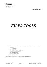
<strong>FIST</strong> Ordering Guide<br />
<strong>FIST</strong><br />
Fiber Infrastructure System Technology<br />
Front Patching/Splicing Shelf<br />
(<strong>FIST</strong>-<strong>FPS</strong>)<br />
This document provides assistance with the selection of the front patching/splicing shelf for use in <strong>FIST</strong><br />
applications. It includes the following sections:<br />
1. PRODUCT DESCRIPTION<br />
2. ORDERING INFORMATION<br />
2.1 Front Patching/Splicing Shelf<br />
2.2 Accessories<br />
2.3 Tools<br />
3. PRODUCT GUIDE<br />
3.1 Shelf Description<br />
3.2 Shelf Dimensions and Mounting Bracket Position<br />
3.3 Accessories Description<br />
3.4 Tools Description<br />
Please consult your local sales engineer for applications not included in this document.<br />
Issue 1.0 (01-01) Page 1 of 10 Product Manager: L.Vleugels
<strong>FIST</strong>-<strong>FPS</strong> Ordering Guide<br />
Front Patching/Splicing Shelf (<strong>FIST</strong>-<strong>FPS</strong>)<br />
1. PRODUCT DESCRIPTION<br />
• The <strong>FIST</strong> Front Patching/Splicing Shelf, <strong>FIST</strong>-<strong>FPS</strong> is a shelf assembly for the fiber<br />
management system that provides the function of cable splicing and patchcord patching<br />
and connecting in a rack environment.<br />
• <strong>FIST</strong>-<strong>FPS</strong> has a capacity of 48 patching points.<br />
• This shelf can be used with Raychem racks as well as with other 19” or metric (ETSI)<br />
racks.<br />
• Multiple configurations are possible:<br />
• Patching only<br />
• Splicing and patching of either loose tube cable or intra-facility cable (IFC)<br />
• The shelf is delivered with a plastic transparent cover that is provided with an<br />
identification system.<br />
Patch/Patch<br />
7N3K1972.JPG<br />
Front Patching/Splicing Shelf<br />
Splice/Patch<br />
7N3K1998.JPG<br />
• All shelves consist of a metal chassis with drawer.<br />
• A metal front patch frame with 4 rows of 12 connector positions is mounted on the<br />
drawer. The connectors will be positioned left or right angled to reduce the risk of eye<br />
damage when working with active fiber.<br />
• Connector adapters can be pre-installed in the patch panel.<br />
• The ‘splicing and patching’ shelf includes a tray tower with 6 FOSC-A splicing trays<br />
behind the patch panel. The splicing trays will include splice holders and a plastic<br />
transparent cover. SMOUV splice protectors are delivered in the kit when applicable.<br />
• Pigtails to be routed from the splicing tray towards the back side of the patch panel can be<br />
included in the ‘splicing and patching’ version of the shelves.<br />
• Positive fiber management of the pigtails and fibers is guaranteed by bend controls on the<br />
drawer and in the splicing trays.<br />
Issue 1.0 (01-01) Page 2 of 10 Product Manager: L.Vleugels
<strong>FIST</strong>-<strong>FPS</strong> Ordering Guide<br />
2. ORDERING INFORMATION<br />
2.1 FRONT PATCHING/SPLICING SHELF<br />
Refer to Section 3 for full product descriptions.<br />
<strong>FIST</strong>-<strong>FPS</strong>-X-X X X-48<br />
Chassis type<br />
M Metric<br />
I 19”<br />
Shelf type<br />
P<br />
Patching only<br />
S<br />
Splicing and patching (loose tube cable or non pre-conn. IFC)<br />
Overlength storage and patching (pre-connectorized IFC)<br />
Tray type/Pigtails<br />
Secondary Splice Jumpers leave shelf<br />
coated pigtails protector RIGHT LEFT<br />
included FRONT FRONT<br />
Not applicable N M<br />
(patching only)<br />
no SMOUV E G<br />
no ANT F H<br />
yes SMOUV I K<br />
yes ANT J L<br />
Connector adapter<br />
with retainer<br />
N<br />
None<br />
A<br />
SC/PC<br />
B<br />
SC/APC<br />
C<br />
FC/PC<br />
D<br />
FC/APC<br />
E<br />
E2000<br />
F<br />
E2000 HRL<br />
K<br />
DIN/PC<br />
M<br />
DIN/APC<br />
O<br />
SC/PC-FC-PC<br />
L<br />
ST (multimode)<br />
Q<br />
ST (single mode)<br />
7N3K2182.JPG<br />
Issue 1.0 (01-01) Page 3 of 10 Product Manager: L.Vleugels
<strong>FIST</strong>-<strong>FPS</strong> Ordering Guide<br />
Standard Kit Content<br />
• Metal shelf assembly including bend controls for guiding the patchcords in the shelf<br />
• Plastic cover with identification cards<br />
• 4 patch modules to hold 12 connectors each<br />
• Pre-mounted connector adapters and retainers<br />
• Secondary coated pigtails when selected (not pre-installed)<br />
• Two trumpets for guiding the patchcords as they enter and exit the shelf<br />
• For the splicing and patching version only:<br />
• Bracket holding 6 FOSC splicing trays including splice holders (SMOUV or ANT)<br />
• SMOUV splice protectors (when applicable)<br />
• A fixation kit for loose tube or intra-facility cable (IFC) (tie wraps and foam)<br />
• Field installable mounting brackets (including screws and cage nuts)<br />
• Installation Instructions<br />
<strong>FIST</strong>-<strong>FPS</strong> kit content<br />
7N3K1951.JPG<br />
Issue 1.0 (01-01) Page 4 of 10 Product Manager: L.Vleugels
<strong>FIST</strong>-<strong>FPS</strong> Ordering Guide<br />
2.2 ACCESSORIES<br />
Name Qty/Pk Description<br />
<strong>FIST</strong>-<strong>FPS</strong>-CT-S-2 1 pc Side cable termination kit for <strong>FIST</strong>-<strong>FPS</strong><br />
(for max. 2 cables)<br />
<strong>FIST</strong>-<strong>FPS</strong>-CT-B-2 1 pc Back cable termination kit for <strong>FIST</strong>-<strong>FPS</strong><br />
(for max. 2 cables)<br />
<strong>FIST</strong>-GS-FLEX-12-50-S5027 50 m Flexible tubing (internal ∅ 12 mm)<br />
2.3 TOOLS<br />
Name Qty/Pk Description<br />
FACC-CAGE-NUT-TOOL 1 pc Cage nut installation tool<br />
FACC-ALLEN-KEY-5-350 1 pc Allen key, ∅ 5 mm, length 350 mm for back<br />
mounting of shelves in rack<br />
Key: pc = piece Qty = quantity Pk = pack<br />
3. PRODUCT GUIDE<br />
3.1 SHELF DESCRIPTION<br />
Chassis and drawer<br />
The <strong>FIST</strong>-<strong>FPS</strong> chassis are ready to be fitted inside an<br />
optical rack using mounting brackets, screws and cage<br />
nuts.<br />
The chassis width is according to the 19” or ETSI<br />
standard.<br />
All chassis are painted (color RAL 7035).<br />
Cover<br />
The shelf contains a hingeable transparent plastic<br />
cover with one central latch. Cards are provided at the<br />
inside of the cover for a clear identification.<br />
7N3K2034.JPG<br />
7N3K2037.JPG<br />
Issue 1.0 (01-01) Page 5 of 10 Product Manager: L.Vleugels
<strong>FIST</strong>-<strong>FPS</strong> Ordering Guide<br />
Mounting brackets<br />
The subrack has field-mountable brackets to<br />
accommodate for:<br />
− mounting specifically for Raychem’s <strong>FIST</strong> racks<br />
− backmounting<br />
− mounting behind the front trumpet<br />
Note: front mounting and mounting with brackets 240<br />
mm from the back of the shelf are impossible because<br />
of the position of the outlet trumpet.<br />
Front patch panel<br />
On the drawer of the shelf, a front patch panel is<br />
mounted. It consists of a metal frame, holding 4<br />
pieces of 12-connector-adapter-modules. The<br />
patching module plane is right or left angle oriented to<br />
reduce the risk of eye damage when working with<br />
active fiber. This also avoids the outgoing jumper<br />
from making strong bends when leaving the shelf.<br />
GSS2OG22.JPG<br />
7N3K2035.JPG<br />
Patching-only configuration*<br />
Patchcords enter the shelf via a trumpet on the right or<br />
left shelf side and are <strong>guide</strong>d via bend controls<br />
towards the back of the patch panel.<br />
Patchcords connected at the front of the patch panel<br />
leave via the trumpet on the left side of the shelf.<br />
Connector adapters are pre-installed.<br />
Splicing and patching configuration*<br />
Loose tube cable or intra-facility cable (IFC) enters via<br />
the right side of the shelf and is <strong>guide</strong>d towards the<br />
splicing trays.<br />
In case of loose tube cable and non-preconnectorized<br />
IFC, fibers are to be spliced to secondary coated<br />
pigtails in the splicing trays and then <strong>guide</strong>d towards<br />
the backside of the patch panel.<br />
In case of preconnectorized IFC, overlength is stored<br />
in the splicing trays, offering the possibility to resplice<br />
damaged IFC to new pigtails.<br />
Patchcords connected at the front of the patch panel<br />
leave via the trumpet on the left side of the shelf.<br />
Connector adapters are pre-installed.<br />
Secondary coated pigtails can be delivered in the kit.<br />
7N3K1972.JPG<br />
7N3K1998.JPG<br />
7N3K2188.JPG<br />
Issue 1.0 (01-01) Page 6 of 10 Product Manager: L.Vleugels
<strong>FIST</strong>-<strong>FPS</strong> Ordering Guide<br />
* Note: The above mentioned configurations describe<br />
the situation where patchcords leave the shelf<br />
at the left side. Patchcords can leave the<br />
shelf at the right side as well.<br />
Trumpet<br />
A trumpet at the side of the shelf protects outgoing<br />
jumpers. A slit at the front side of the trumpet allows<br />
for easy reconfiguration of the jumpers to other<br />
shelves.<br />
<strong>FPS</strong>PT.JPG<br />
7N3K1962.JPG<br />
3.2 SHELF DIMENSIONS AND MOUNTING BRACKET POSITION<br />
Dimensions<br />
Width<br />
(with/without mounting brackets)<br />
Chassis standard<br />
ETSI 19”<br />
531 / 494 mm 481 / 444 mm<br />
Height<br />
125 mm<br />
(requires 5 metric HUs)*<br />
125 mm<br />
(requires 3 19" HUs)<br />
Depth 280 mm 280 mm<br />
* A HU is a ‘height unit’. Refer to rack documentation for more details.<br />
Issue 1.0 (01-01) Page 7 of 10 Product Manager: L.Vleugels
<strong>FIST</strong>-<strong>FPS</strong> Ordering Guide<br />
Mounting bracket position<br />
Different mounting positions:<br />
1. BACK mounting<br />
2. <strong>FIST</strong>-GR mounting (13.5 mm from back)<br />
3. FRONT mounting (165 mm from back)<br />
Notes:<br />
For easy entry and exit of cables and pigtails via the trumpets, a 100 mm free space (left<br />
and right of the shelf) is recommended.<br />
For back termination of cables a 40 mm free space (at the back of the shelf) is<br />
recommended.<br />
For side termination of cables a 160 mm free space (aside the shelf) is recommended.<br />
Issue 1.0 (01-01) Page 8 of 10 Product Manager: L.Vleugels
<strong>FIST</strong>-<strong>FPS</strong> Ordering Guide<br />
3.3 ACCESSORIES DESCRIPTION<br />
Side cable termination kit<br />
<strong>FIST</strong>-<strong>FPS</strong>-CT-S-2<br />
Kit to terminate max. 2 cables at the side of the shelf.<br />
Back cable termination kit<br />
<strong>FIST</strong>-<strong>FPS</strong>-CT-B-2<br />
Kit to terminate max. 2 cables at the back of the shelf.<br />
7N3K1948.JPG<br />
Small flexible tubing<br />
<strong>FIST</strong>-GS-FLEX-12-50-S5027<br />
Flexible tubing with inside diameter of 12 mm.<br />
7N3K1947.JPG<br />
RA11.JPG<br />
Issue 1.0 (01-01) Page 9 of 10 Product Manager: L.Vleugels
<strong>FIST</strong>-<strong>FPS</strong> Ordering Guide<br />
3.4 TOOLS DESCRIPTION<br />
Cage nut tool<br />
FACC-CAGE-NUT-TOOL<br />
Tool to install cage nuts in the rack.<br />
Long Allen key<br />
FACC-ALLEN-KEY-5-350<br />
Allen key, diameter 5 mm, length 350 mm for backmounting<br />
of shelves in rack.<br />
TO23.JPG<br />
TO04.JPG<br />
OG<strong>FPS</strong>.DOC<br />
Tyco, Raychem and <strong>FIST</strong> are trademarks of Tyco International<br />
The information given herein, including drawings, illustrations and schematics which are intended for illustration purposes<br />
only, is believed to be reliable. However, Tyco Electronics makes no warranties as to its accuracy or completeness and<br />
disclaims any liability in connection with its use. Tyco Electronics’ obligations shall only be as set forth in Tyco<br />
Electronics’ Standard Terms and Conditions of Sale of this product and in no case will Tyco Electronics be liable for any<br />
incidental, indirect or consequential damages arising out of the sale, resale, use or misuse of the product.<br />
Users of Tyco Electronics products should make their own evaluation to determine the suitability of each such product for<br />
the specific application.<br />
© Copyright Tyco Electronics 2000<br />
Issue 1.0 (01-01) Page 10 of 10 Product Manager: L.Vleugels