

Read On-line - Light Speed Engineering
Read On-line - Light Speed Engineering
Read On-line - Light Speed Engineering

Create successful ePaper yourself
Turn your PDF publications into a flip-book with our unique Google optimized e-Paper software.
Align plate concentric to crankshaft by registering on centering<br />
tabs. Visually align crankcase split <strong>line</strong> with the v notches<br />
between the top and bottom 2 holes of the mounting plate. Mark<br />
the crankcase mounting locations through the existing holes in<br />
the bracket. If possible, use a #2 centering drill for a pilot hole.<br />
Drill #6 (0.2040) x 5/8” deep. Tap ¼-20. For best results, use a<br />
2-flute spiral point HSS tap with aluminum tapping fluid such as<br />
Tap-Magic. <strong>On</strong>ce the bracket is mounted to the crankcase,<br />
remove the three alignment tabs then remove the two control<br />
tabs. This sequence allows you to later verify that the alignment<br />
tabs were removed. If the circuit board was removed for this<br />
operation, re-install it. All screws holding the crank sensor circuit<br />
board to the mounting plate must be secured with Loctite and the<br />
proper torque. The 0 degree mark on the circuit board should<br />
now align with the split <strong>line</strong> in the crankcase when the screws are<br />
fastened in the center of their positioning slot.<br />
Now that the sensor plate is installed perform a simple operational check: disconnect<br />
all high tension leads from the ignition coils. With power to the system and all else<br />
connected, take any magnet and swipe it back and forth past each sensor (speed is<br />
important, > 2x per second). Every other pass should produce a loud spark at the<br />
coil. <strong>On</strong>ly the south pole works. Check each sensor.<br />
Lycoming external engine dimensions can vary significantly, so you need to verify<br />
the proper clearance between the sensor and the magnets installed in the flywheel<br />
surface. Two measurements need to be compared to determine the gap.<br />
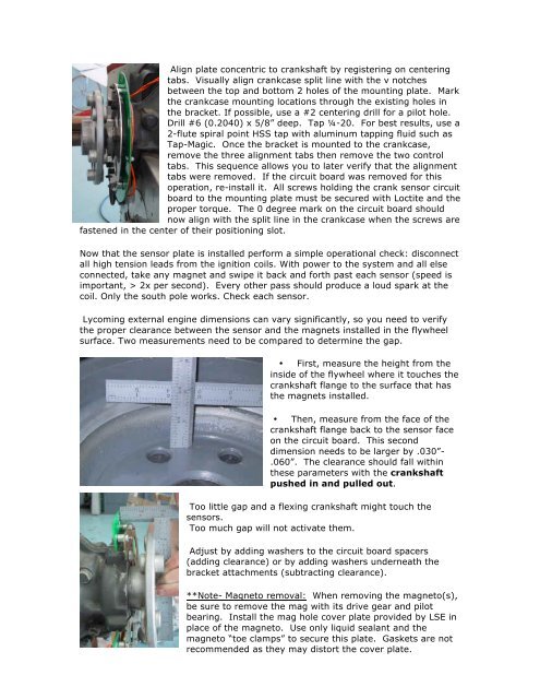
• First, measure the height from the<br />
inside of the flywheel where it touches the<br />
crankshaft flange to the surface that has<br />
the magnets installed.<br />
• Then, measure from the face of the<br />
crankshaft flange back to the sensor face<br />
on the circuit board. This second<br />
dimension needs to be larger by .030”-<br />
.060”. The clearance should fall within<br />
these parameters with the crankshaft<br />
pushed in and pulled out.<br />
Too little gap and a flexing crankshaft might touch the<br />
sensors.<br />
Too much gap will not activate them.<br />
Adjust by adding washers to the circuit board spacers<br />
(adding clearance) or by adding washers underneath the<br />
bracket attachments (subtracting clearance).<br />
**Note- Magneto removal: When removing the magneto(s),<br />
be sure to remove the mag with its drive gear and pilot<br />
bearing. Install the mag hole cover plate provided by LSE in<br />
place of the magneto. Use only liquid sealant and the<br />
magneto “toe clamps” to secure this plate. Gaskets are not<br />
recommended as they may distort the cover plate.