

Read On-line - Light Speed Engineering
Read On-line - Light Speed Engineering
Read On-line - Light Speed Engineering

You also want an ePaper? Increase the reach of your titles
YUMPU automatically turns print PDFs into web optimized ePapers that Google loves.
The 4 cylinder trigger coil system uses two equally spaced sensors (the 6 cylinder<br />
system uses three sensors) mounted on the supplied precision plate and firmly<br />
bolted to the crank case. This is the lightest, most reliable and cost effective method<br />
to provide accurate timing information to the system.<br />
<strong>On</strong> any four cycle engine, regardless of the number of cylinders, only two trigger<br />
bolts are installed on the crankshaft, prop-extension or fly-wheel. However, the<br />
number of trigger coils changes with the number of cylinders.<br />
A four cylinder engine requires two coils phased 180° apart to produce the two firing<br />
cycles per revolution. A six cylinder system requires three coils 120° apart to<br />
produce three sparks per revolution.<br />
The mounting of trigger coils and bolts is critical for proper operation and is<br />
explained in detail in drawing 3a, 3b, or 3c. LSE provides accurate mounting plates<br />
for most engines. The installation must be tested with an automotive type, clip-on<br />
timing light before flight as described in Section Three.<br />
1.3 HALL EFFECT MODULE<br />
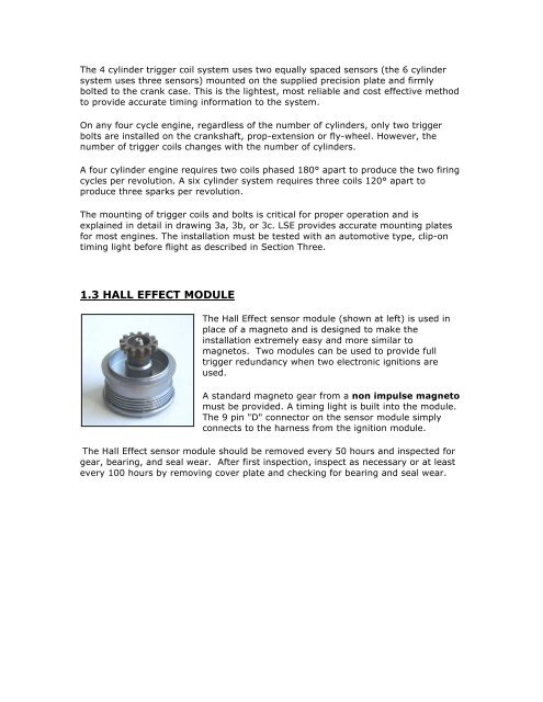
The Hall Effect sensor module (shown at left) is used in<br />
place of a magneto and is designed to make the<br />
installation extremely easy and more similar to<br />
magnetos. Two modules can be used to provide full<br />
trigger redundancy when two electronic ignitions are<br />
used.<br />
A standard magneto gear from a non impulse magneto<br />
must be provided. A timing light is built into the module.<br />
The 9 pin "D" connector on the sensor module simply<br />
connects to the harness from the ignition module.<br />
The Hall Effect sensor module should be removed every 50 hours and inspected for<br />
gear, bearing, and seal wear. After first inspection, inspect as necessary or at least<br />
every 100 hours by removing cover plate and checking for bearing and seal wear.