
Create successful ePaper yourself
Turn your PDF publications into a flip-book with our unique Google optimized e-Paper software.
drw 753-<strong>400</strong><br />
OPERATION AND MAINTENANCE<br />
MODEL <strong>415</strong>-<strong>400</strong> REGULATORS rev 001019; 030418D; 080529; 090519; 091112<br />
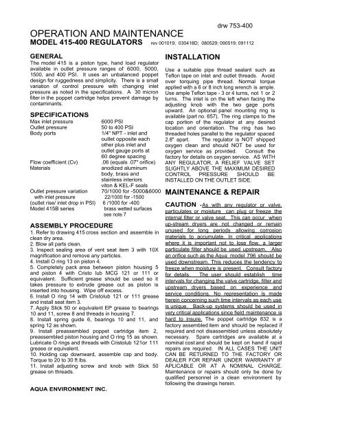
GENERAL<br />
The model <strong>415</strong> is a piston type, hand load regulator<br />
available in outlet pressure ranges of 6000, 5000,<br />
1500, and <strong>400</strong> PSI. It uses an unbalanced poppet<br />
design for ruggedness and simplicity. There is a small<br />
variation of control pressure with changing inlet<br />
pressure as noted in the specifications. A 30 micron<br />
filter in the poppet cartridge helps prevent damage by<br />
contaminants.<br />
SPECIFICATIONS<br />
Max inlet pressure<br />
6000 PSI<br />
Outlet pressure<br />
50 to <strong>400</strong> PSI<br />
Body ports<br />
1/4" NPT - inlet and<br />
outlet opposite each<br />
other plus inlet and<br />
outlet gauge ports at<br />
60 degree spacing<br />
Flow coefficient (Cv) .06 (equals .07" orifice)<br />
Materials<br />
anodized aluminum<br />
body, brass and<br />
stainless interiors<br />
viton & KEL-F seals<br />
Outlet pressure variation 70/1000 for -5000&6000<br />
with inlet pressure 22/1000 for -1500<br />
(outlet rise/ inlet drop in PSI) 6 /1000 for -<strong>400</strong><br />
Model <strong>415</strong>B series brass wetted surfaces<br />
see note 7<br />
ASSEMBLY PROCEDURE<br />
1. Refer to drawing <strong>415</strong> cross section and assemble in<br />
clean dry area.<br />
2. Blow all parts clean.<br />
3. Inspect sealing area of vent seat item 3 with 10X<br />
magnification and remove any particles.<br />
4. Install O ring 13 on piston 4.<br />
5. Completely pack area between piston housing 5<br />
and piston 4 with Cristo lub MCG 121 or 111 or<br />
equivalent. Sufficient grease should be used so it<br />
takes pressure to extrude grease out as piston is<br />
inserted into housing. Wipe off excess.<br />
6. Install O ring 14 with Cristolub 121 or 111 grease<br />
and install seat item 3.<br />
7. Apply Slick 50 or equivalent EP grease to bearings<br />
10 and 11, screw 8 and threads in housing 7.<br />
8. Install spring guide 6, bearings 10 and 11, and<br />
spring 12 as shown.<br />
9. Install preassembled poppet cartridge item 2,<br />
preassembled piston housing and O ring 15 as shown.<br />
Lubricate O rings and threads with Cristolub 121or 111<br />
grease or equivalent.<br />
10. Holding cap downward, assemble cap and body.<br />
Torque to 20 to 30 ft lbs.<br />
11. Install adjusting screw and knob with Slick 50<br />
grease on threads.<br />
AQUA ENVIRONMENT INC.<br />
INSTALLATION<br />
Use a suitable pipe thread sealant such as<br />
Teflon tape on inlet and outlet threads. Avoid<br />
over torquing pipe thread. Normal torque<br />
applied with a 6 or 8 inch long wrench is ample.<br />
Use ample Teflon tape - 3 or 4 turns, not 1 or 2<br />
turns. The inlet is on the left when facing the<br />
adjusting knob with the two gage ports<br />
upward. An optional panel mounting ring is<br />
available (part no. 657). The ring clamps to the<br />
cap portion of the regulator at any desired<br />
location and orientation. The ring has two<br />
threaded holes parallel to the regulator spaced<br />
2.8" apart. The regulator is NOT shipped<br />
oxygen clean and should NOT be used for<br />
oxygen service as provided. Consult the<br />
factory for details on oxygen service. AS WITH<br />
ANY REGULATOR, A RELIEF VALVE SET<br />
SLIGHTLY ABOVE THE MAXIMUM DESIRED<br />
CONTROL PRESSURE SHOULD BE<br />
INSTALLED ON THE OUTLET SIDE.<br />
MAINTENANCE & REPAIR<br />
CAUTION -As with any regulator or valve,<br />
particulates or moisture can plug or freeze the<br />
internal filter or valve seat. This can occur when<br />
up-stream dryers are not changed or remain<br />
unused for long periods allowing corrosion<br />
materials to accumulate. In critical applications<br />
where it is important not to lose flow, a larger<br />
particulate filter should be used upstream. Also<br />
an orifice such as the Aqua model 796 should be<br />
used downstream. This reduces the tendency to<br />
freeze when moisture is present. Consult factory<br />
for details. The user should establish time<br />
intervals for changing the valve cartridge, filter and<br />
upstream dryers based on experience and<br />
service conditions. No representation is made<br />
herein concerning such time intervals as each use<br />
is unique. Back-up systems should be used in<br />
very critical applications since field maintenance is<br />
hard to insure. The poppet cartridge 832 is a<br />
factory assembled item and should be replaced if<br />
required and not disassembled unless absolutely<br />
necessary. Spare cartridges are available at a<br />
nominal cost and should be kept on hand if rapid<br />
repairs are required. IN ALL CASES THE UNIT<br />
CAN BE RETURNED TO THE FACTORY OR<br />
DEALER FOR REPAIR UNDER WARRANTY IF<br />
APLICABLE OR AT A NOMINAL CHARGE.<br />
Maintenance or repairs should only be done by<br />
qualified personnel in a clean environment by<br />
following the drawings herein.
drw 753-<strong>400</strong> pg 2<br />
ASSEMBLY AND DISASSEMBLY<br />
Assembly and disassembly can be done using the following<br />
drawings and parts list.<br />
PARTS LIST - <strong>415</strong> REGULATOR<br />
ITEM QTY PART NO. DESCRIPTION<br />
1 1 407 body<br />
2 1 832 poppet cartridge<br />
3 1 726-1 vent seat<br />
1 1062-1 non-venting seat (optional)<br />
4 1 744 piston for - <strong>400</strong> PSI<br />
5 1 746 piston housing for - <strong>400</strong><br />
see note 1<br />
6 1 410 spring guide - see note 2<br />
7 1 474 cap<br />
8 1 378-2 adjusting screw<br />
9 1 379-30 knob<br />
10 2 379-37 bearing plate<br />
11 1 379-38 thrust bearing<br />
12 1 379-5 spring<br />
13 1 2-122 - 75V seal for - <strong>400</strong> PSI<br />
14 1 2-010 - 90V seal<br />
15 1 2-028 - 90V seal for -<strong>400</strong>)<br />
16 1 2-013 - 90V seal ref.<br />
17 1 849 spring guide, lower<br />
18 not used<br />
PARTS LIST - 832 POPPET CARTRIDGE<br />
ITEM QTY PART NO. DESCRIPTION<br />
1 1 808 retainer nut<br />
2 1 8016 poppet housing<br />
3 1 809 sleeve<br />
4 1 807 seat<br />
5 1 741 poppet<br />
9<br />
Vent<br />
10<br />
11<br />
12<br />
13<br />
14<br />
15<br />
16<br />
Inlet<br />
8<br />
6<br />
7<br />
17<br />
5<br />
4<br />
3<br />
2<br />
Outlet<br />
1<br />
6 1 2-009 - 90V seal<br />
7 1 2-013 - 90V seal<br />
8 1 832-8 spring<br />
9 1 832-9 filter<br />
NOTES<br />
1. Mount piston housing 746 with smoother side downward against<br />
seal.<br />
2. mount spring guide 410 with bevel side toward adjusting screw.<br />
3. On <strong>415</strong>-<strong>400</strong> model mount piston hsg 746 with smooth side<br />
toward O ring.<br />
4. Part number 839 -xxxx repair kit includes; 1 ea. 832 cartridge,<br />
1 ea. 2-010 O ring, 1 ea. 2-028 O ring, 1 ea. 726 vent seat, 1 ea.<br />
piston and piston O ring. For the -5000 piston hsg 833 is included.<br />
5. Model <strong>415</strong>-XXXXNA (non adjustable) - delete items 8& 9 and<br />
replace with 3/8-24 x 1/4" lg. hex head plated bolt and jam nut.<br />
6. Non-vented is <strong>415</strong>-XXXXNV and uses p/n1062 as item 3<br />
7. brass version <strong>415</strong>B-xxxx items 1,4,& 5 are brass<br />
6<br />
7<br />
8<br />
9<br />
5<br />
4<br />
3<br />
2<br />
1<br />
AQUA ENVIRONMENT INC.