1 Purpose 2 Definitions 3 References - Bosch
1 Purpose 2 Definitions 3 References - Bosch
1 Purpose 2 Definitions 3 References - Bosch
You also want an ePaper? Increase the reach of your titles
YUMPU automatically turns print PDFs into web optimized ePapers that Google loves.
Sbd SPECIFIC Draft 1<br />
GENERAL DELIVERY SPECIFICATION Page 1 3 rd Edition<br />
SECTION 10 of 16<br />
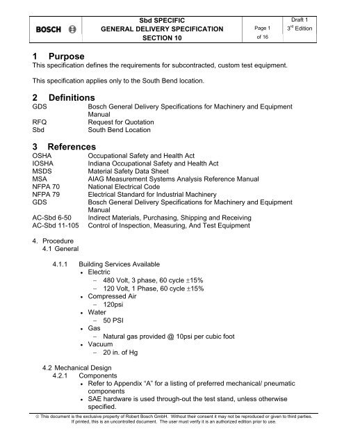
1 <strong>Purpose</strong><br />
This specification defines the requirements for subcontracted, custom test equipment.<br />
This specification applies only to the South Bend location.<br />
2 <strong>Definitions</strong><br />
GDS<br />
RFQ<br />
Sbd<br />
3 <strong>References</strong><br />
OSHA<br />
IOSHA<br />
MSDS<br />
MSA<br />
NFPA 70<br />
NFPA 79<br />
GDS<br />
AC-Sbd 6-50<br />
AC-Sbd 11-105<br />
4. Procedure<br />
4.1 General<br />
<strong>Bosch</strong> General Delivery Specifications for Machinery and Equipment<br />
Manual<br />
Request for Quotation<br />
South Bend Location<br />
Occupational Safety and Health Act<br />
Indiana Occupational Safety and Health Act<br />
Material Safety Data Sheet<br />
AIAG Measurement Systems Analysis Reference Manual<br />
National Electrical Code<br />
Electrical Standard for Industrial Machinery<br />
<strong>Bosch</strong> General Delivery Specifications for Machinery and Equipment<br />
Manual<br />
Indirect Materials, Purchasing, Shipping and Receiving<br />
Control of Inspection, Measuring, And Test Equipment<br />
4.1.1 Building Services Available<br />
• Electric<br />
− 480 Volt, 3 phase, 60 cycle ±15%<br />
− 120 Volt, 1 Phase, 60 cycle ±15%<br />
• Compressed Air<br />
− 120psi<br />
• Water<br />
− 50 PSI<br />
• Gas<br />
− Natural gas provided @ 10psi per cubic foot<br />
• Vacuum<br />
− 20 in. of Hg<br />
4.2 Mechanical Design<br />
4.2.1 Components<br />
• Refer to Appendix “A” for a listing of preferred mechanical/ pneumatic<br />
components<br />
• SAE hardware is used through-out the test stand, unless otherwise<br />
specified.<br />
© This document is the exclusive property of Robert <strong>Bosch</strong> GmbH. Without their consent it may not be reproduced or given to third parties.<br />
If printed, this is an uncontrolled document. The user must verify it is an authorized edition prior to use.
Sbd SPECIFIC Draft 1<br />
GENERAL DELIVERY SPECIFICATION Page 2 3 rd Edition<br />
SECTION 10 of 16<br />
4.2.1.2.1 When applicable, the preferred choice for safety relays and E –<br />
Stop buttons are: Button – Square D part # 9001-TRM4-Y205,<br />
Safety Relay – STI part # SA10MD or Telemecanique – part #<br />
XPS-AT-5110. If necessary, an equivalent part may be substituted.<br />
• Test Stand enclosures are Stainless Steel or standard frame with Stainless<br />
Steel panels.<br />
4.3 Wire Termination and Labeling<br />
4.3.1 Wiring methods<br />
• The intent of this document is to insure that <strong>Bosch</strong> standards are adhered to<br />
in the wiring of new test equipment. These methods are based on the<br />
NFPA 70 & NFPA 79 standards. If a condition is not outlined or defined in<br />
this document, then the NFPA 70 or 79 should be consulted for clarification.<br />
4.3.2 Conductor sizing:<br />
• Conductor ampacity shall be sized appropriately as defined in NFPA 79<br />
Sec. 16, Table 11. For example:<br />
AWG Raceway @ 60<br />
Deg. C<br />
Enclosure @ 60<br />
Deg. C<br />
24 2 2<br />
22 3 3<br />
20 5 5<br />
18 7 7<br />
16 10 10<br />
14 15 20<br />
12 20 25<br />
10 30 40<br />
8 40 60<br />
6 55 80<br />
4 70 105<br />
3 85 120<br />
2 95 140<br />
1 110 165<br />
0 125 195<br />
2/0 145 225<br />
3/0 165 260<br />
4/0 195 300<br />
See NFPA 79 Sec. 15.3<br />
4.3.3 Conductor type:<br />
• Conductors shall be of types MTW, THHN, THWN, or THW with the<br />
characteristics listed in NFPA 79 Sec. 15.1.1<br />
• Multiconductor flexible power cords shall be of types SO, STO, STOW or<br />
SJO, SJOW, SJTO with the characteristics listed in NFPA 79 Sec. 15.1.1<br />
© This document is the exclusive property of Robert <strong>Bosch</strong> GmbH. Without their consent it may not be reproduced or given to third parties.<br />
If printed, this is an uncontrolled document. The user must verify it is an authorized edition prior to use.
Sbd SPECIFIC Draft 1<br />
GENERAL DELIVERY SPECIFICATION Page 3 3 rd Edition<br />
SECTION 10 of 16<br />
• Jacketed multiconductor assemblies shall be composed of PVC unless<br />
frequent exposure to brake fluid is expected. In which case, Teflon<br />
jacketing and insulation should be used.<br />
• Conductors shall conform to standards outlined in NFPA 79 Sec. 15.2<br />
• Temperature rating<br />
• Minimum rating should not fall below 80 deg. C. unless ambient temperature<br />
dictates higher rating.<br />
• Voltage rating<br />
• Minimum rating of 300 V for control wiring, 600 V for power.<br />
4.3.4 Wire termination<br />
• Ferules shall be used at all termination points unless another type of<br />
connector is indicated.<br />
• No more than two conductors shall be terminated at each terminal<br />
connection.<br />
• All panels shall be equipped with terminal blocks or attachment plugs for all<br />
out going control conductors.<br />
• Signal wires need not have a terminal block or attachment plug where signal<br />
loss, and or noise, may be of concern.<br />
• All wires shall be labeled at their termination point to correspond to the<br />
markings on the diagrams.<br />
• Device and component designation shall be consistent with Annex E of<br />
NFPA 79:<br />
4.3.5 Splicing<br />
• Splicing is prohibited.<br />
4.3.6 Spare Wire<br />
• A minimum of 15% spare wire shall exist in each wireway that is external to<br />
an enclosure. All wires must be labeled, terminated, and identified in the<br />
electrical prints.<br />
4.3.7 Color Code<br />
• See Appendix “B”.<br />
4.4 Wiring for Low Electrical Noise<br />
4.4.1 The mechanical layout of test stands and panels within must include electrical<br />
noise considerations. Control and high current circuitry shall be physically<br />
separated and shielded as much as possible from transducers and signal<br />
conditioners.<br />
4.4.2 Position signal conditioners and shunt cal relays as close as possible to<br />
transducers.<br />
4.4.3 Position high current drivers such as solenoid and motor drives in a shielded<br />
compartment as near the load as possible.(24 Vdc solenoids are preferred<br />
when possible – less noise)<br />
© This document is the exclusive property of Robert <strong>Bosch</strong> GmbH. Without their consent it may not be reproduced or given to third parties.<br />
If printed, this is an uncontrolled document. The user must verify it is an authorized edition prior to use.
Sbd SPECIFIC Draft 1<br />
GENERAL DELIVERY SPECIFICATION Page 4 3 rd Edition<br />
SECTION 10 of 16<br />
4.4.4 Bring control and data acquisition wiring to computer from different directions to<br />
reduce coupling. Wires placed at 90 degree angles will magnetically couple<br />
the least.<br />
4.4.5 Always route and bundle noisy driver and digital control signals separately from<br />
low-level analog signals.<br />
4.4.6 Reduce loop area of signals and their respective return lines by twisting or<br />
running closely parallel.<br />
4.4.7 Route wires close to grounded metal surfaces rather than out in space.<br />
4.4.8 All sub-assemblies must be well grounded to the test stand chassis.<br />
Assemblies attached only with painted rack mount ears must be grounded with<br />
a strap.<br />
4.4.9 Ground power supply commons at a single point on the chassis near the power<br />
supply unless otherwise specified.<br />
4.4.10 Do not use switching power supplies unless specifically requested.<br />
4.4.11 All transducers shall be connected to a signal conditioner using twisted pairs in<br />
a shielded cable. A pair for excitation, a pair for output, and a third pair for<br />
shunt cal if required. All transducer cable shields shall be grounded only at<br />
one end.<br />
4.4.12 Closely follow all recommendations for motor drive wiring. Be sure to include<br />
all filters. Ground shield of high-current drive output cables at both ends.<br />
4.5 Electrical Schematic Format<br />
4.5.1 Electrical Layout Diagram – This diagram shall show an overview of the Test<br />
System identifying all electrical enclosures, motors and electrical components.<br />
4.5.2 Control Wiring Diagram – This section should contain all logic circuits used in<br />
the test system.<br />
4.5.3 Power Wiring Diagram – This section should contain all power feed and<br />
devices.<br />
4.5.4 Interconnection Diagram – This section should contain all terminal blocks,<br />
connectors, and indicate which elements are connected to them.<br />
4.6 Electric Cylinder Guidelines:<br />
4.6.1 With minimal stroke travel, grease may not circulate to properly lubricate Exlar<br />
Cylinder bearing surface.<br />
4.6.2 Exlar powered at 480VAC, 3 Phase is preferred.<br />
4.6.3 Servo controller should be real-time and should receive relevant control and<br />
shutdown parameters directly.<br />
4.6.4 For shutdown, power to amplifier should have a delay factor allowing the drive<br />
signal to be zero first.<br />
4.6.5 Exlar control should include external limit and home proximity switches. As<br />
travel limit is exceeded, logic should remain detected.<br />
4.6.6 Exlar cylinders should include external anti-rotate fixturing.<br />
4.6.7 If power goes below a predetermined value, shutdown should occur.<br />
*Proposed due to possible storm/ facility power interruptions.<br />
4.6.8 For high speed applications, one should specify amplifier with sufficient current<br />
output.<br />
© This document is the exclusive property of Robert <strong>Bosch</strong> GmbH. Without their consent it may not be reproduced or given to third parties.<br />
If printed, this is an uncontrolled document. The user must verify it is an authorized edition prior to use.
Sbd SPECIFIC Draft 1<br />
GENERAL DELIVERY SPECIFICATION Page 5 3 rd Edition<br />
SECTION 10 of 16<br />
4.6.9 Exlar GSX model cyclinders with parallelled windings are physically smaller<br />
than GS models but are rated for shorter life (less of a problem for short<br />
functional tests).<br />
4.7 PC Software (Exception: PLC’s)<br />
4.7.1 General<br />
• The main program should be written with Microsoft Visual Basic. Active X<br />
objects or real-time critical modules may be written with Microsoft Visual<br />
C++ but must be well documented.<br />
• All software developed for a <strong>Bosch</strong> Corporation Test System will be the<br />
property of <strong>Bosch</strong> Corporation and may be duplicated and re-used as <strong>Bosch</strong><br />
Corporation deems appropriate.<br />
• All software developed for a <strong>Bosch</strong> Corporation Test System will be<br />
provided with source code and relevant necessary libraries. Libraries<br />
necessary for code execution must be available at no additional charge for<br />
duplication and re-use by <strong>Bosch</strong> Corporation.<br />
• The software version should be encoded into the program code to be part of<br />
the test display. Also, record the description of the test system software<br />
revision in a text file maintained with the source code.<br />
• Revision format will be: X.Y.Z<br />
− X represents a large revision that begins at 1. Y and Z are set to 0.<br />
− Y represents a small revision that begins at 0 and is incremented Z is<br />
set to 0.<br />
− Z represents a developmental status of the software. Z begins at 0<br />
and may be incremented whenever development software is being<br />
tested.<br />
4.7.2 Input Data Configuration<br />
• Whenever possible, input configurations shall be stored/accessed using<br />
Windows ASCII INI file format.<br />
4.7.3 Process Communications<br />
• Whenever possible, process communication shall be implemented using<br />
any or all of the following: Ethernet TCP/IP, Ethernet UDP/IP, Component<br />
Object Model (COM), Named Pipes or Shared Memory.<br />
4.7.4 Test Data Output<br />
• Whenever possible, test data output will be in Windows ASCII INI format. It<br />
will include a header section containing, at a minimum, date, test stand<br />
number, sample rate, software version, units of the recorded data and<br />
scaling necessary to convert between the recorded data units and their<br />
associated engineering units. The data section shall include a single<br />
header record containing channel names. Both the header and data will be<br />
tab delimited. Data is to be stored as time by record and channels by<br />
column. Once created, the test data output file is not allowed to change.<br />
4.8 Quality Standards & Run-Off Conditions<br />
© This document is the exclusive property of Robert <strong>Bosch</strong> GmbH. Without their consent it may not be reproduced or given to third parties.<br />
If printed, this is an uncontrolled document. The user must verify it is an authorized edition prior to use.
Sbd SPECIFIC Draft 1<br />
GENERAL DELIVERY SPECIFICATION Page 6 3 rd Edition<br />
SECTION 10 of 16<br />
4.8.1 The Quality standards & run-off conditions as described in the GDS Manual,<br />
Section 6 are not applicable.<br />
4.8.2 Test stand measurement repeatability is performed as described in the AIAG<br />
Measurement System Analysis Handbook.<br />
• n=3<br />
• Minimum of 10 groupings (30 data points)<br />
• Calculate<br />
− Data average xbar<br />
− Grand average xdoublebar<br />
− Data Range<br />
R<br />
− Upper Control Limit UCL<br />
− Lower Control Limit LCL<br />
• Plot xbar & R charts<br />
• Evaluate<br />
4.8.3 Test stand measurement repeatability is performed for all required tests listed<br />
on the Test System Summary Sheet (sheet provided by <strong>Bosch</strong>).<br />
• Test system capability and variance columns are completed.<br />
4.9 Final Acceptance Checklist<br />
4.9.1 Upon completion of the Equipment at Seller’s facility, Buyer shall have the right<br />
to inspect the Equipment using Appendix “C” as a minimum list of<br />
requirements. The Buyer and Seller may agree to have the Buyer perform a<br />
pre-completion inspection or several inspections during the build process. In<br />
addition to any purchase order requirements, delivery to the buyer’s facility as<br />
well as final payment requires that Appendix “C” issues be reviewed and<br />
approved by the Buyer.<br />
© This document is the exclusive property of Robert <strong>Bosch</strong> GmbH. Without their consent it may not be reproduced or given to third parties.<br />
If printed, this is an uncontrolled document. The user must verify it is an authorized edition prior to use.
Sbd SPECIFIC<br />
GENERAL DELIVERY SPECIFICATION Page 7 3 rd Edition<br />
SECTION 10 of 16<br />
4.10 Procedure<br />
1.<br />
Is the test system a<br />
stand alone?<br />
No<br />
The following is Reviewed:<br />
• Dimensions of DUT<br />
• Delivery<br />
• HSE Considerations<br />
• Test System Input/Output<br />
• Software Requirements<br />
• Recommended Parts<br />
• Changing Requirements<br />
• Accuracy<br />
5. RFQ is reviewed<br />
6. Request for<br />
Quotation is issued<br />
The following factors are<br />
included:<br />
• Timeline<br />
• Material Costs<br />
• Labor Costs<br />
• HSE Considerations<br />
• <strong>Bosch</strong> RFQ Number<br />
• Relevant Part Numbers<br />
• Name of Requestor<br />
• Delivery Date<br />
• Documentation in English<br />
• Foundation Requirements<br />
• <strong>Bosch</strong> Ownership of Custom<br />
Software and Documentation<br />
7. Vendor prepares<br />
quotation<br />
8. Purchase Order<br />
is issued<br />
• GDS Section 10<br />
• Recommended Parts List<br />
• AC/Sbd 6-50<br />
• GDS Section 10<br />
• GDS Appendix 1.1<br />
• AC/Sbd 6-50<br />
• GDS Appendix 1.1<br />
Yes<br />
2.<br />
Is the test system<br />
a duplicate of<br />
existing <strong>Bosch</strong><br />
equipment<br />
No<br />
Yes<br />
Design Review can include the<br />
following:<br />
• Engineering Requirements<br />
• Accuracy Requirements<br />
• Mechanical Design<br />
• Electrical Design<br />
• Pneumatic Design<br />
• Hydraulic Design<br />
• Software Design<br />
• HSE<br />
9. A Design Review<br />
is conducted<br />
• GDS Section 10<br />
Documentation can include the<br />
following:<br />
• English Text<br />
• English Units<br />
• DXF Compatible CAD<br />
• 3 Copies<br />
• Electrical Drawings<br />
• Mechanical Layout<br />
• Pneumatic Drawings<br />
• Hydraulic Drawings<br />
• Operation Manual<br />
• Control System Overview<br />
10. Equipment is<br />
documented<br />
• GDS Section 10<br />
Equipment is built and tested to<br />
<strong>Bosch</strong> Standards<br />
11. Equipment is built<br />
and tested<br />
• GDS Section 10<br />
Acceptance can be at the<br />
vendor's facility or at the <strong>Bosch</strong><br />
plant.<br />
Acceptance includes but is not<br />
totally based on the following:<br />
• Compliance to Electrical Code<br />
• Compliance to Test Stand<br />
Summary Sheet Requirements<br />
• Workmanship<br />
• MSA Data - 10 sets of 3 data<br />
points<br />
12. Equipment is<br />
accepted by <strong>Bosch</strong><br />
3.<br />
Is the cost less than<br />
$100K?<br />
No<br />
Yes<br />
Exceptions to the following may<br />
be granted by the Project<br />
Engineer:<br />
• Quotation<br />
• Design Review<br />
• Parts Selection<br />
• Electrical Design<br />
• Mechanical Design<br />
• Pneumatic Design<br />
• Health and Safety<br />
• Documentation<br />
• Quality<br />
• Acceptance<br />
4. Comply with GDS<br />
• GDS Section 10<br />
• AC/Sbd 11-105<br />
• GDS<br />
• GDS Section 10<br />
© This document is the exclusive property of Robert <strong>Bosch</strong> GmbH. Without their consent it may not be reproduced or given to third parties.<br />
If printed, this is an uncontrolled document. The user must verify it is an authorized edition prior to use.
Sbd SPECIFIC Draft 1<br />
GENERAL DELIVERY SPECIFICATION Page 8 3 rd Edition<br />
SECTION 10 of 16<br />
4.11 Roles and Responsibilities<br />
Flowchart<br />
block #<br />
1. Is the test system a stand<br />
alone?<br />
2. Is the test system a<br />
duplicate of existing <strong>Bosch</strong><br />
Equipment?<br />
Roles and Responsibilities Matrix<br />
Function <strong>Bosch</strong> <strong>Bosch</strong><br />
Engineering Purchasing<br />
<strong>Bosch</strong><br />
User<br />
Group<br />
<strong>Bosch</strong><br />
Test<br />
Equipment<br />
Representative<br />
I (s) R I<br />
Vendor<br />
I (s) R I<br />
3. Is the cost less than<br />
s (s) R I<br />
$100K?<br />
4. Comply with GDS. (R) s (R) R<br />
5. RFQ is reviewed. s (R) s R I<br />
6. Request for quotation is s R s s I<br />
issued.<br />
7. Vendor prepares quotation. I (I) I R<br />
8. Purchase order is issued. R I<br />
9. A design review is<br />
s (I) s s, I R<br />
conducted.<br />
10. Equipment is documented I R<br />
11. Equipment is built and<br />
I<br />
R<br />
tested.<br />
12. Equipment is accepted by<br />
<strong>Bosch</strong>.<br />
s s s R s<br />
Key:<br />
R = Function is responsible for execution/completion of the activity/action.<br />
A = Function is responsible for approval in the action/activity.<br />
s = Function is responsible to support/cooperate during the activity/action.<br />
I = Function receives/processes information that is an output of the action/activity.<br />
( ) Indicates the responsibility is carried out on an as needed basis.<br />
© This document is the exclusive property of Robert <strong>Bosch</strong> GmbH. Without their consent it may not be reproduced or given to third parties.<br />
If printed, this is an uncontrolled document. The user must verify it is an authorized edition prior to use.
Sbd SPECIFIC Draft 1<br />
GENERAL DELIVERY SPECIFICATION Page 9 3 rd Edition<br />
SECTION 10 of 16<br />
Appendix “A”<br />
<strong>Bosch</strong> Approved Parts<br />
Part Type<br />
Air Cylinders<br />
Air Fittings<br />
Cable Clamps<br />
Circuit Breakers<br />
Connectors<br />
Contactors<br />
Contacts/Pins<br />
Current Shunts<br />
Cycle Counters<br />
Data Acquisition Cards<br />
Displacement Transducers<br />
Manufacturer<br />
Ortman<br />
Advanced Engineering<br />
Control Air<br />
Parker<br />
SMC<br />
3M<br />
AMP<br />
Amphenol<br />
Cinch<br />
ITT<br />
Northern Technologies<br />
Panduit<br />
Thomas Bett<br />
Bussman<br />
Merlin Gerlin<br />
Potter & Brumfield<br />
Siemens<br />
Square D (Schnieder Electric)<br />
AMP<br />
Amphenol<br />
Cannon<br />
Cinch<br />
SPC Technologies<br />
Superior Electronics<br />
ABB<br />
AEG<br />
IEC<br />
Merlin Gerwin<br />
Siemens<br />
Square D (Schnieder Electric)<br />
Telemecanique<br />
AMP<br />
EMPRO<br />
Durant<br />
Electromatic<br />
ITT<br />
Potter Brumsfeld<br />
Red Lion<br />
Reddington<br />
Veeder Root<br />
National Instruments<br />
Balluff<br />
Macro Sensors<br />
Unimeasure<br />
© This document is the exclusive property of Robert <strong>Bosch</strong> GmbH. Without their consent it may not be reproduced or given to third parties.<br />
If printed, this is an uncontrolled document. The user must verify it is an authorized edition prior to use.
Sbd SPECIFIC Draft 1<br />
GENERAL DELIVERY SPECIFICATION Page 10 3 rd Edition<br />
SECTION 10 of 16<br />
Part Type<br />
Electric Actuators<br />
Electric Actuator Drives<br />
Enclosures<br />
Flow Meters<br />
Flow Rate/Totalizers<br />
Flow Transmitters<br />
Fuse Holders<br />
Fuses<br />
Parker<br />
Exlar<br />
Copley<br />
Emerson<br />
Bud<br />
Hammond<br />
Hoffman<br />
Cox<br />
Fluidyne<br />
Hedland<br />
Max Machinery<br />
Flow Technology<br />
Max Machinery<br />
Max Machinery<br />
Buss<br />
Littelfuse<br />
Phoenix<br />
Siemens<br />
Buss<br />
Gould-Shawmut<br />
Littlefuse<br />
Manufacturer<br />
Hydraulic Fittings<br />
Indicators<br />
Panel Meters<br />
PLC Displays<br />
PLC Perpheral I/O<br />
Siemens<br />
Hansen<br />
Parker<br />
Chicago Miniature Lamp, Inc.<br />
GE<br />
Micro Lamps, Inc.<br />
Radion<br />
Square D (Schnieder Electric)<br />
Sylvania<br />
Acculex<br />
Datel<br />
Modutec<br />
Omega<br />
Syrelec<br />
Cuttler-Hammer<br />
Square D (Schnieder Electric)<br />
<strong>Bosch</strong><br />
Phoenix<br />
Siemans<br />
SMC<br />
Square D (Schnieder Electric)<br />
Wago<br />
© This document is the exclusive property of Robert <strong>Bosch</strong> GmbH. Without their consent it may not be reproduced or given to third parties.<br />
If printed, this is an uncontrolled document. The user must verify it is an authorized edition prior to use.
Sbd SPECIFIC Draft 1<br />
GENERAL DELIVERY SPECIFICATION Page 11 3 rd Edition<br />
SECTION 10 of 16<br />
Part Type<br />
Pneumatic Valves / Solenoids<br />
Potentiometers<br />
Power Supply / Conditioning<br />
Manufacturer<br />
MAC<br />
Parker<br />
SMC<br />
Beckman Instruments, Inc.<br />
Bourns<br />
Clarostat<br />
Computer Instruments, Inc.<br />
Duncan Electronics Inc.<br />
Helipot Corporation<br />
IRC<br />
Ohmite<br />
Spectrol<br />
Trimpot<br />
Control Techniques<br />
HarrisLambda/EMI<br />
Schaeffner<br />
Siemens<br />
Sola<br />
Sorensen<br />
Square D<br />
Telemecanique<br />
Triplite<br />
Pressure Transducers GP - 50<br />
Sensotec<br />
Viatran<br />
PLC Controllers<br />
Proximity Switches<br />
Relay Sockets<br />
Modicon<br />
Steeplechase<br />
WAGO<br />
Balluff<br />
Turck<br />
Omron<br />
Potter & Brumfield<br />
SPC<br />
Square D (Schnieder Electric)<br />
© This document is the exclusive property of Robert <strong>Bosch</strong> GmbH. Without their consent it may not be reproduced or given to third parties.<br />
If printed, this is an uncontrolled document. The user must verify it is an authorized edition prior to use.
Sbd SPECIFIC Draft 1<br />
GENERAL DELIVERY SPECIFICATION Page 12 3 rd Edition<br />
SECTION 10 of 16<br />
Relays<br />
Part Type<br />
Manufacturer<br />
<strong>Bosch</strong><br />
IDEC<br />
Opto 22<br />
Phoenix<br />
Potter & Brumfield<br />
Siemens<br />
Square D (Schnieder Electric)<br />
STI<br />
Telemecanique<br />
Servo Controllers<br />
Servo Valves<br />
Signal Conditioning<br />
Supercons<br />
MEI<br />
MTS<br />
HR Textron<br />
MOOG<br />
MTS<br />
Daytronic<br />
Interface<br />
National Instruments<br />
Phoenix<br />
Sensotec<br />
Telmar<br />
Superior Electric Co.<br />
Switches<br />
Teflon Hose (Stainless Steel Braid)<br />
Terminal Blocks<br />
Thermocouples<br />
Alco<br />
Honeywell<br />
IFM Efector<br />
Siemens<br />
Square D (Schnieder Electric)<br />
STI<br />
River Bend<br />
Phoenix Contact<br />
Siemens<br />
WAGO<br />
Omega<br />
Thermo Electric<br />
© This document is the exclusive property of Robert <strong>Bosch</strong> GmbH. Without their consent it may not be reproduced or given to third parties.<br />
If printed, this is an uncontrolled document. The user must verify it is an authorized edition prior to use.
Sbd SPECIFIC Draft 1<br />
GENERAL DELIVERY SPECIFICATION Page 13 3 rd Edition<br />
SECTION 10 of 16<br />
Part Type<br />
Transducers - Force<br />
Transducers - Torque<br />
Vacuum Transducers<br />
Wire<br />
Wire Terminations<br />
Wire Ferrules<br />
Interface<br />
Key<br />
Lebow<br />
Sensor Data<br />
Sensotec<br />
Lebow<br />
Sensor Data<br />
MKS<br />
Sensotec<br />
Viatran<br />
Alpha<br />
Belden<br />
Olflex<br />
Waytec<br />
AMP<br />
Ideal<br />
Panduit<br />
SPC<br />
American<br />
Eclipse<br />
SPC<br />
Wiedmuller<br />
Manufacturer<br />
© This document is the exclusive property of Robert <strong>Bosch</strong> GmbH. Without their consent it may not be reproduced or given to third parties.<br />
If printed, this is an uncontrolled document. The user must verify it is an authorized edition prior to use.
Sbd SPECIFIC Draft 1<br />
GENERAL DELIVERY SPECIFICATION Page 14 3 rd Edition<br />
SECTION 10 of 16<br />
Appendix “B”<br />
Wiring Methods<br />
Color code<br />
Control wiring:<br />
Conductor insulation color should conform to NFPA 79 Sec. 16.1.2 and 16.1.3.<br />
For example:<br />
Black: Ungrounded control, load and line conductors @ line voltage.<br />
Red: Ungrounded AC control conductors below line voltage.<br />
Blue: Ungrounded DC control conductors.<br />
White: Grounded AC conductors.<br />
White w/Blue: DC return conductors.<br />
Green: Chassis Ground.<br />
Note: Line voltage should be considered to be 200VAC and above.<br />
Instrumentation wiring:<br />
Instrumentation wire color code shall conform to the following table. <strong>Bosch</strong> will be<br />
informed if an alternate cable is used which deviates from the standard.<br />
Signal 6-Pin Conn. 9-Pin Conn Pair Cable Cable Cable Cable<br />
8434* 89503* 83556* 83506*<br />
+ Excitation A 1 TP1 Red Red Red Red<br />
+ Signal B 2 TP2 Green Green Green Green<br />
- Signal C 3 TP2 White Black White White<br />
- Excitation D 4 TP1 Black Black Black Black<br />
Cal 1 E 5 TP3 Shd (6 pin) White Blue Blue<br />
Cal 2 F 6 TP3 Black Orange Orange<br />
Shield Case 9 Drain Shd (9 pin) Shield Shield Shield<br />
25AWG 24AWG 22AWG 24AWG<br />
*Belden Cable Number<br />
© This document is the exclusive property of Robert <strong>Bosch</strong> GmbH. Without their consent it may not be reproduced or given to third parties.<br />
If printed, this is an uncontrolled document. The user must verify it is an authorized edition prior to use.
Sbd SPECIFIC Draft 1<br />
GENERAL DELIVERY SPECIFICATION Page 15 3 rd Edition<br />
SECTION 10 of 16<br />
Appendix “C”<br />
Acceptance Check-List<br />
Item<br />
1. GDS Section 10 Compliance<br />
2. Compliance to <strong>Bosch</strong> approved parts List<br />
3. Bill of Material List<br />
4. Wire Termination and Labeling<br />
5. Wire color code<br />
6. Compliance to NFPA Electrical Code<br />
7. Compliance to Test System Summary Sheet<br />
8. Compliance to <strong>Bosch</strong> MSA requirements(Section 10 4.6)<br />
9. Compliance to Safety & Health Standards:<br />
10. Health & Safety reviewed with <strong>Bosch</strong> project engineer?<br />
11. All hazard areas must be guarded (push, stroke, capture,<br />
retract, clip and squeeze areas, sharp edges, hot/cold<br />
surfaces, etc).<br />
12. E-stop located within close reach of operator near point of<br />
operation?<br />
13. Emergency Stop (E-stop) buttons for electrical, pneumatic,<br />
and hydraulic test systems are accessible and properly<br />
labeled?<br />
14. E-stop does not require software processing to disable test<br />
system motion?<br />
15. E-stop requires manual release and operator intervention to<br />
restart?<br />
16. Demonstrates proper test execution sequence and timing?<br />
17. Test data is in ascii text format for export compatibility?<br />
18. D-U-T mounting dimensioning agrees with our products?<br />
19. 3 copies of Documentation provided in DXF Compatible<br />
CAD with English text.<br />
20. Documentation includes the following:<br />
Electrical Drawings<br />
Mechanical Layout<br />
Pneumatic Drawings<br />
Hydraulic Drawings<br />
Operation Manual<br />
Control System Overview<br />
21. Test System appearance is neat, professional?<br />
Acceptable<br />
Yes No N/A<br />
© This document is the exclusive property of Robert <strong>Bosch</strong> GmbH. Without their consent it may not be reproduced or given to third parties.<br />
If printed, this is an uncontrolled document. The user must verify it is an authorized edition prior to use.
Sbd SPECIFIC Draft 1<br />
GENERAL DELIVERY SPECIFICATION Page 16 3 rd Edition<br />
SECTION 10 of 16<br />
5 Change History<br />
Edition No.: 1 Date: 8/30/2002 Written by: AC/ETS6.3-Jack Brewer<br />
Changes:<br />
• Original document.<br />
Edition No.: 2 Date: 8/8/2003 Written by: AC/ETS6.3-Jack Brewer<br />
Changes:<br />
• Revised sections 4.3 Wire Termination and Labeling.<br />
• Added section 4.4 Wiring for Low Electrical Noise.<br />
• Added section 4.6 Electric Cylinder Guidelines.<br />
• Revised section 4.7 PC Software.<br />
• Revised section 4.9 Final Acceptance Checklist.<br />
• Revised appendices A, B, and C.<br />
Edition No.: 3 Date: 9/13/2004<br />
Approved: AC/ETS7.1-Jack Brewer<br />
Changes:<br />
• Sections 4.2.1.2: Added description and part number for E-Stop button and safety relay.<br />
• Section 4.6.7: Replaced “E-Stop” with “shutdown”.<br />
• Revised Appendix A Parts List.<br />
© This document is the exclusive property of Robert <strong>Bosch</strong> GmbH. Without their consent it may not be reproduced or given to third parties.<br />
If printed, this is an uncontrolled document. The user must verify it is an authorized edition prior to use.


