Trane Water-Cooled Chiller Model RTHB Brochure RLC-DS-1
Trane Water-Cooled Chiller Model RTHB Brochure RLC-DS-1
Trane Water-Cooled Chiller Model RTHB Brochure RLC-DS-1

You also want an ePaper? Increase the reach of your titles
YUMPU automatically turns print PDFs into web optimized ePapers that Google loves.
<strong>RLC</strong>-<strong>DS</strong>-1<br />
November 1999<br />
Revised<br />
<strong>RLC</strong>-<strong>DS</strong>-1<br />
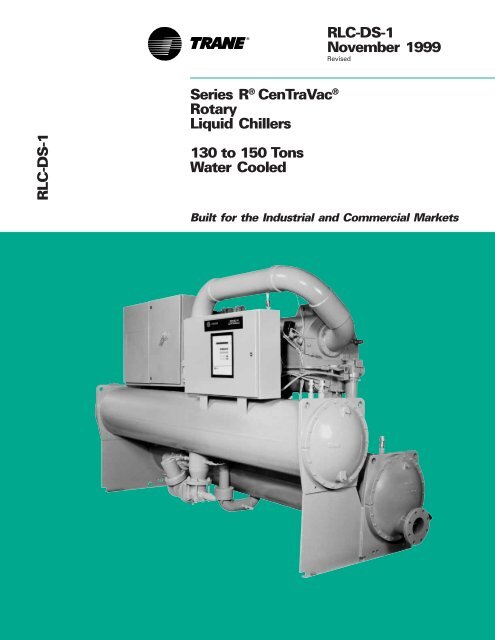
Series R ® CenTraVac ®<br />
Rotary<br />
Liquid <strong>Chiller</strong>s<br />
130 to 150 Tons<br />
<strong>Water</strong> <strong>Cooled</strong><br />
Built for the Industrial and Commercial Markets
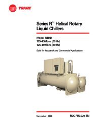
Introduction<br />
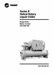
<strong>Trane</strong> Series R ® <strong>Chiller</strong> –<br />
<strong>Model</strong> <strong>RTHB</strong><br />
The <strong>RTHB</strong> offers high reliability, ease of<br />
installation, and high energy efficiency<br />
due to its advanced design, low speed/<br />
direct-drive compressor and proven<br />
Series R chiller performance.<br />
The major advantages of the <strong>RTHB</strong> are:<br />
99.5% reliable.<br />
High energy efficiency.<br />
Compact size.<br />
Optional bolt-together construction.<br />
• Low maintenance.<br />
The Series R helical rotary chiller is an<br />
industrial grade design built for the<br />
commercial market. It is ideal for office<br />
buildings, hospitals, schools, retailers<br />
and industrials.<br />
©American Standard Inc. 1999<br />
2
Features<br />
and<br />
Benefits<br />
Contents<br />
The Series R ® Helical Rotary<br />
Compressor<br />
• Direct-drive, low speed for high<br />
efficiency and high reliability.<br />
• Simple design with only three moving<br />
parts, resulting in high reliability and low<br />
maintenance.<br />
• Field servicable compressor for easy<br />
maintenance.<br />
• Precise rotor tip clearance for optimal<br />
efficiency.<br />
• Liquid refrigerant cooled motor. The<br />
motor operates at lower temperatures<br />
for longer motor life.<br />
• Five minute start-to-start/two minute<br />
stop-to-start anti-recycle timer allows<br />
for closer water loop temperature<br />
control.<br />
• Years of research and testing. The <strong>Trane</strong><br />
helical rotary compressor has amassed<br />
thousands of hours of testing, much of it<br />
at severe operating conditions beyond<br />
normal air conditioning applications.<br />
• Proven track record. The <strong>Trane</strong><br />
Company is the world’s largest<br />
manufacturer of large helical rotary<br />
compressors. Over 60,000 commercial<br />
and industrial installations worldwide<br />
have proven that the <strong>Trane</strong> helical<br />
rotary compressor has a reliability rate<br />
of greater than 99.5 percent in the first<br />
year of operation — unequalled in the<br />
industry.<br />
Applications<br />
Comfort cooling.<br />
Industrial process cooling.<br />
Ice/thermal storage.<br />
Heat recovery.<br />
• Low temperature process cooling.<br />
Electronic Expansion Valve<br />
Better part load efficiency.<br />
Extended operating range.<br />
• Optimized refrigerant metering for<br />
more efficient control.<br />
Advanced Heat Transfer Surfaces<br />
• Condenser and evaporator tubes use<br />
the latest heat transfer technology for<br />
increased efficiency.<br />
Compact Size<br />
• Designed with the retrofit and<br />
replacement market in mind.<br />
• Fits through standard double-width<br />
doors.<br />
• Optional bolt-together construction for<br />
easy unit disassembly.<br />
• Small footprint of Series R chiller saves<br />
valuable equipment room space.<br />
Simple Installation<br />
• Lightweight design simplifies rigging<br />
requirements. Reduces cost and<br />
speeds installation time.<br />
• Simplified piping; the only water piping<br />
required is for the evaporator and<br />
condenser.<br />
• No oil cooler or purge system<br />
connections.<br />
• Simple power connection.<br />
• Standard unit mounted starter<br />
eliminates additional jobsite labor<br />
requirements.<br />
• Extensive factory testing.<br />
• Full factory refrigerant and oil charge<br />
further reducing field labor, materials<br />
and installation cost.<br />
Microprocessor Controls With UCP2<br />
• Microprocessor-based unit control<br />
panel (UCP2) monitors and controls<br />
chiller operation and associated<br />
sensors, actuators, relays and switches.<br />
Control unit is entirely factory<br />
assembled and tested.<br />
• Proportional integral derivative (PID)<br />
control strategy for stable, efficient<br />
chilled water temperature control.<br />
• Exclusive Adaptive Control design to<br />
keep chiller on-line under adverse<br />
conditions.<br />
• Standard electrical demand limiting.<br />
• Chilled water reset for energy savings<br />
during part load operation.<br />
• Complete range of chiller safety<br />
controls.<br />
• Easy to use operator interface. Panel<br />
displays all operating and safety<br />
messages with complete diagnostics<br />
information.<br />
• Clear language display is easy to read.<br />
The Standard clear language display<br />
panel supports eight languages<br />
including English, French, German,<br />
Spanish, Katakana, Italian, Portuguese<br />
and Dutch. An optional display panel is<br />
available to display Chinese, Japanese<br />
Kanji, Thai and Korean languages.<br />
• Generic building automation system<br />
points available.<br />
• Over 120 diagnostics and operating<br />
points including chiller current draw,<br />
condenser pressure and evaporator<br />
pressure are standard displays.<br />
Integrated Comfort System Interface<br />
• Microprocessor UCP2 easily interfaces<br />
with <strong>Trane</strong> Tracer ® and Tracer Summit ®<br />
building automation/energy<br />
management computer for Integrated<br />
Comfort systems benefits; all with a<br />
single twisted pair wire.<br />
Availability<br />
• The Series R ® chiller is in stock and<br />
available now for quick ship needs.<br />
• Packed stock inventory features<br />
standard configurations for immediate<br />
delivery.<br />
• <strong>Trane</strong> offers the fastest ship cycles in<br />
the industry on built-to-order units.<br />
3<br />
Introduction 2<br />
Features and Benefits 3<br />
<strong>Model</strong> Number Description 5<br />
Refrigeration Cycle 6<br />
Selection Procedure 7<br />
Application Considerations 9<br />
Dimensional Data 10<br />
Jobsite Connections 13<br />
Controls 14<br />
Typical Wiring Diagrams 16<br />
Mechanical Specification 18<br />
Those applications in this catalog<br />
specifically excluded from the ARI<br />
certification program are:<br />
• Low temperature applications, including<br />
ice storage<br />
• Glycol<br />
• 50 Hz unit components<br />
<strong>Water</strong> <strong>Chiller</strong> Systems<br />
Business Unit
Features<br />
and<br />
Benefits<br />
Complex Character Clear Language Display<br />
with Multi-Language Control Interface<br />
<strong>Trane</strong> has multi-language support for all<br />
chillers controlled by the UCP2 control<br />
panel. The standard clear language<br />
display (CLD) supports eight languages<br />
including English, French, German,<br />
Spanish, Katakana, Italian, Portuguese<br />
and Dutch. The Complex Character CLD<br />
was added to support languages such<br />
as Traditional and Simplified Chinese,<br />
Japanese Kanji, Thai and Korean<br />
whose characters could not be formed<br />
on the standard display .<br />
• Super-twist LCD display with<br />
backlighting for readability.<br />
• Access to all available chiller data (more<br />
than 200 items) including:<br />
- Setpoints<br />
- Field start-up items<br />
- Machine configuration items<br />
- Service test items<br />
• Easily accessible reports, in logical<br />
groupings, including:<br />
- <strong>Chiller</strong> report<br />
- Refrigerant report<br />
- Compressor report<br />
• Custom report capability for data<br />
arranged the way you want to see it.<br />
• Alarm and diagnostic capability<br />
including:<br />
- More than 100 different diagnostic<br />
messages<br />
- Log of the last 20 diagnostics<br />
- An indicator to let you know when<br />
an alarm is present<br />
- Expanded help messages for each<br />
alarm to let you know what action to<br />
take<br />
- Operator security<br />
- Internationally recognized symbols<br />
<strong>Trane</strong> Complex Character CLD<br />
available for all chillers with UCP2<br />
control panel.<br />
The Complex Character CLD is<br />
available as a retrofit kit for the standard<br />
CLD on the UCP2 panel. With the same<br />
wiring and mounting, it is as simple as<br />
disconnecting two wires, unbolting the<br />
existing CLD, bolting on the Complex<br />
Character CLD and reconnecting the<br />
two wires.<br />
4
<strong>Model</strong><br />
Number<br />
Description<br />
RTH B 150 F M A0 0 L W P 0 T U N N 3 L F 2 L F V Q U<br />
1,2,3 4 5,6,7 8 9 10,11 12 13 14 15 16 17 19 20 21 22 23 24 25 26 27 28 30 31<br />
Digits 01, 02, 03 — Series R ® CTV<br />
RTH = Series R CenTraVac ®<br />
Digit 04 — Dev Sequence<br />
B = 2nd Major Development<br />
Digits 05,06,07 — Nominal Tons<br />
130 = 130 Nominal Tons<br />
150 = 150 Nominal Tons<br />
Digit 08 — UNIT VOLTAGE<br />
A = 200/60/3<br />
C = 230/60/3<br />
D = 380/60/3<br />
R = 380/50/3<br />
N = 400/50/3<br />
U = 415/50/3<br />
F = 460/60/3<br />
H = 575/60/3<br />
S = SPECIAL<br />
Digit 09<br />
L = Lowest Nominal Kw Motor For<br />
Compressor Size<br />
M = Medium Nominal Kw Motor For<br />
Compressor Size<br />
H = Highest Nominal Kw Motor For<br />
Compressor Size<br />
Digits 10, 11 — Design Sequence<br />
A0 = “First Design, etc. Increment When<br />
Parts” Are Affected For Service<br />
Purposes.<br />
Digit 12 — Unit Specials<br />
0 = No Unit Specials<br />
C = All Unit Specials Are Denoted By<br />
Digits Elsewhere In The <strong>Model</strong><br />
Number<br />
S = Unit Has An Uncatagorized Special<br />
Not Denoted By A Digit Elsewhere In<br />
The <strong>Model</strong> Number<br />
Digit 13 — Shell Length<br />
N = Standard (Short) Shells<br />
L = High Eff. (Long) Shells<br />
Digit 14 — Unit Structure<br />
W = Welded<br />
B = Separable<br />
Digit 15 — Control Options<br />
0 = Without Options Module<br />
P = With Options Module<br />
Digit 16 — Printer Interface<br />
0 = Without Printer Interface<br />
P = With Printer Interface<br />
Digit 19 — Starter Type<br />
U = Unit Mounted Starter<br />
(See Starter <strong>Model</strong> No.)<br />
Digit 20 — Evap Temp Range<br />
N = Standard and Low Temp Range<br />
(Above 20 F)<br />
V = Very Low Temp Range<br />
(20 F and Below)<br />
Digit 22 — Evap <strong>Water</strong> Passes<br />
2 = 2 Pass<br />
3 = 3 Pass<br />
4 = 4 Pass<br />
S = Special Customer Option<br />
Digit 23 — Evap Connections<br />
L = 150 Psi Flanged Connections<br />
H = 300 Psi Flanged Connections<br />
S = Special Customer Option<br />
Digit 24 — Evap Tubes<br />
F = Standard 06A High-Perf Tubes<br />
S = Special Customer Option<br />
Digit 25 — Cond <strong>Water</strong> Passes<br />
2 = 2 Pass<br />
3 = 3 Pass<br />
S = Special Customer Option<br />
Digit 26 — Cond Connections<br />
L = 150 Psi Flanged Connections<br />
H = 300 Psi Flanged Connections<br />
M = 300 Psi Marine Grooved Connections<br />
S = Special Customer Option<br />
Digit 27 — Cond Tubes<br />
F = Standard I-E Finned Tubes<br />
G = Smooth Bore Copper Tubes<br />
H = Smooth Bore 90/10 CU-NI Tubes<br />
Digit 28 — Isolation Valve<br />
0 = No Condenser Isolation Valve<br />
V = With Condenser Isolation Valve<br />
Digit 30 — Thermal Insulation<br />
0 = Without Thermal Insulation<br />
Q = With Thermal Insulation<br />
S = Special Customer Option<br />
Digit 31 — Agency Listing<br />
0 = No Agency Listing<br />
U = C/UL Listed<br />
Note: Position numbers not shown are<br />
currently unassigned. Not all<br />
combinations are available on all sizes.<br />
Digit 17 — ICS Interface<br />
0 = Without Tracer Communications<br />
T = Tracer Communications (COMM 3)<br />
M = Tracer Summit Communications<br />
(COMM 4)<br />
5
Refrigeration<br />
Cycle<br />
The Series R ® CenTraVac ® chiller, like<br />
other <strong>Trane</strong> CenTraVac chillers, is<br />
designed for reliability and efficiency.<br />
Features such as direct drive, reliable<br />
motor cooling, electronic expansion<br />
valve/fixed orifice refrigerant flow<br />
control and an economizer cycle have<br />
all been incorporated into the design of<br />
the Series R CenTraVac chiller.<br />
During operation, liquid refrigerant is<br />
distributed along the length of the<br />
flooded evaporator uniformly coating<br />
each tube. As it cools the system water<br />
flowing through the evaporator tubes,<br />
the refrigerant absorbs heat causing it<br />
to vaporize.<br />
The gaseous refrigerant is then drawn<br />
through the suction cavity in the<br />
evaporator and into the compressor<br />
where the compression process begins.<br />
Partially compressed evaporator<br />
refrigerant vapor in the compressor is<br />
joined by vapor produced during the<br />
motor cooling process and the<br />
economizer cycle at an intermediate<br />
point in the compression cycle. The<br />
combined refrigerant vapor streams<br />
are then fully compressed and the hot<br />
refrigerant vapor is discharged to the<br />
condenser.<br />
Baffles within the condenser shell<br />
distribute the compressed refrigerant<br />
gas evenly across the condenser tube<br />
bundle. Cooling tower water circulates<br />
through the condenser tubes and<br />
absorbs heat from this refrigerant,<br />
causing it to condense.<br />
Once the liquid refrigerant leaves the<br />
bottom of the condenser, it passes<br />
through an electronic expansion valve.<br />
Because of the pressure drop created<br />
by the electronic expansion valve, some<br />
of the liquid vaporizes. The resulting<br />
mixture of liquid and gaseous<br />
refrigerant then enters the motor<br />
housing, where it uniformly surrounds<br />
and cools the motor. Motor heat<br />
absorbed by the refrigerant causes<br />
more of the liquid refrigerant to “flash”<br />
to a gas.<br />
All of the refrigerant vapor available at<br />
this point is “economized” — that is,<br />
routed directly to the rotor section of the<br />
compressor housing. The liquid<br />
refrigerant leaves the motor housing,<br />
passes through a fixed orifice system<br />
and returns to the evaporator<br />
continuing the cycle.<br />
Compressor Description<br />
The compressor used in Series R<br />
CenTraVac chillers has three distinct<br />
sections: the motor, the rotor and the oil<br />
separator.<br />
Motor Section<br />
The hermetic 3600 rpm motor is an<br />
induction type motor and is cooled by<br />
liquid refrigerant.<br />
Rotor Section<br />
Each Series R CenTraVac uses a<br />
helirotor type compressor. Each<br />
compressor has only three moving<br />
parts: two rotors and a slide valve. The<br />
male rotor is directly attached to and<br />
driven by the motor. The female rotor is,<br />
in turn, driven by the male rotor.<br />
Separately housed bearing sets are<br />
provided at each end of both rotors. The<br />
slide valve is located, and moves, along<br />
the top of these rotors.<br />
The helirotor compressor is a positive<br />
displacement compressor. Refrigerant<br />
from the evaporator is drawn into the<br />
suction opening at the bottom of the<br />
compressor rotor section. After being<br />
compressed by the meshing action of<br />
the rotor teeth, the high pressure<br />
refrigerant gas is discharged from the<br />
end of the rotors directly into the oil<br />
separator.<br />
Oil sprayed along the top of the<br />
compressor rotor section bathes both<br />
rotors along with the compressor<br />
housing interior. While the oil injected<br />
here does provide lubrication for the<br />
driving action of the rotors, its primary<br />
purpose is to seal the clearance spaces<br />
that exist between the rotors and<br />
compressor housing. Effective seals<br />
between these internal parts enhance<br />
compressor efficiency by limiting<br />
leakage between the high and low<br />
pressure cavities.<br />
Capacity control is accomplished by a<br />
slide valve in the rotor section of the<br />
compressor. Positioned along the top<br />
of the rotors and parallel to the rotors;<br />
the slide valve is driven by a piston/<br />
cylinder.<br />
Compressor loading is determined by<br />
the position of the slide valve over<br />
the rotors. When the slide valve is<br />
fully extended over the rotors the<br />
compressor is fully loaded. Unloading<br />
occurs as the slide valve is drawn<br />
towards the discharge side of the<br />
compressor since compression no<br />
longer occurs over the entire length of<br />
the compressor rotor section. Slide<br />
valve unloading lowers refrigeration<br />
capacity by shortening the effective<br />
length of the rotors.<br />
Oil Separator Section<br />
The oil separator section of the<br />
compressor is located at the discharge<br />
end of the compressor.<br />
Once oil is injected into the interior of the<br />
compressor’s rotor section, it mixes with<br />
compressed refrigerant vapor and is<br />
then discharged into the oil separator by<br />
the rotors. The oil separator consists of<br />
a perforated cylinder that surrounds a<br />
helical passageway. As the refrigerant<br />
and oil mixture travels through this<br />
passageway, centrifugal force forces<br />
the oil to collect on the walls of the<br />
cylinder and passes through<br />
perforations to the cylinder’s exterior. Oil<br />
that accumulates on this surface then<br />
runs off the cylinder and collects in an oil<br />
sump located at the bottom of the<br />
housing.<br />
Meanwhile, the compressed refrigerant<br />
vapor, stripped of oil droplets, continues<br />
its passage through the oil separator<br />
and enters the discharge line leading to<br />
the condenser.<br />
Figure RC-1 – Refrigerant Cycle Diagram<br />
6
Selection<br />
Procedure<br />
The Series R ® chiller performance is<br />
rated in accordance with ARI Standard<br />
550/590-98 Certification Program.<br />
<strong>Chiller</strong> selections and performance<br />
information can be obtained through the<br />
use of the Series R chiller selection<br />
program available through local <strong>Trane</strong><br />
sales offices.<br />
Performance<br />
The Series R computer selection<br />
program provides performance data for<br />
each chiller selection at the full load<br />
design point and part load operating<br />
points as required.<br />
It should be noted that changing the<br />
number of water passes or the water<br />
flow rates may significantly alter the<br />
performance of a particular chiller. To<br />
obtain the maximum benefit from the<br />
wide range of selections available,<br />
designers are encouraged to develop<br />
performance specifications and use the<br />
computer selection program outputs to<br />
optimize their selections. This will allow<br />
the selection of the particular<br />
compressor-evaporator-condenser<br />
combination which most closely meets<br />
the job requirements. All selections<br />
should be made using the computer<br />
selection program.<br />
Fouling Factors<br />
ARI Standard 550 includes a definition<br />
of clean tube fouling. Recommended<br />
field fouling allowances have not<br />
changed on a relative basis; the<br />
standard fouling adjustment is a<br />
0.00010 increment from 0.0000 “clean”<br />
for the evaporator and 0.00025<br />
increment from 0.0000 “clean” for the<br />
condenser.<br />
<strong>Chiller</strong> specifications should be<br />
developed using the most current<br />
standard fouling factors.<br />
Unit Performance with Fluid Media<br />
Other Than <strong>Water</strong><br />
Series R chillers can be selected with a<br />
wide variety of media other than water.<br />
Typically used media include ethylene<br />
glycol or propylene glycol either in the<br />
evaporator, condenser or both. <strong>Chiller</strong>s<br />
using media other than water are<br />
excluded from the ARI Standard<br />
550/590-98 Certification Program, but<br />
are rated in accordance with ARI<br />
Standard 550/590-98. <strong>Trane</strong> factory<br />
performance tests are only performed<br />
with water as the cooling and heat<br />
rejection medium. For media other than<br />
water, contact the local <strong>Trane</strong> sales<br />
office for chiller selections and<br />
information regarding factory<br />
performance testing.<br />
Dimensional Drawings<br />
The dimensional drawings illustrate<br />
overall measurements of the unit. The<br />
service clearances indicate clearances<br />
required to easily service the<br />
recommended Series R chiller.<br />
All catalog dimensional drawings are<br />
subject to change. Current submittal<br />
drawings should be referred to for<br />
detailed dimensional information.<br />
Contact the local <strong>Trane</strong> sales office for<br />
submittal information.<br />
Electrical Data Tables<br />
Compressor motor electrical data is<br />
shown in the data section for each<br />
compressor size. Rated load amperes<br />
(RLA), locked rotor wye amperes<br />
(LRAY) and locked rotor delta amperes<br />
(LRAD) for standard voltages of all<br />
50 and 60 Hertz, 3 phase motors are<br />
shown. The RLA is based on the<br />
performance of the motor developing<br />
full rated horsepower. The kW rating of<br />
the motor will equal or exceed the kW<br />
requirement determined by the Series<br />
R computer selection program at design<br />
conditions. If motor kW draw at design<br />
conditions is less than the kW rating of<br />
the motor, the RLA at design conditions<br />
is determined by multiplying the motor<br />
RLA (at the desired voltage) by the ratio<br />
of design kW to the motor kW rating.<br />
This is done by the Series R chiller<br />
computer selection program. RLA is<br />
available in the selection program as<br />
part of the design predictions. Predicted<br />
values include power factor variation<br />
from point to point.<br />
A voltage utilization range is tabulated<br />
for each voltage listed. Series R chillers<br />
are designed to operate satisfactorily<br />
over a utilization range of ± 10 percent<br />
of the standard design voltages of 200<br />
V, 230 V, 380 V, 460 V, and 575 V for<br />
60 Hertz, 3 phase and 380 V, 400 V,<br />
415 V for 50 Hertz, 3 phase.<br />
7<br />
Evaporator and Condenser<br />
Pressure Drop<br />
Pressure drop data is determined by the<br />
Series R chiller computer selection<br />
program available through local <strong>Trane</strong><br />
sales offices.<br />
Part Load Performance<br />
The Series R chiller possesses excellent<br />
part load performance characteristics.<br />
Actual air conditioning system loads are<br />
usually significantly less than full load<br />
design conditions. Therefore, the chillers<br />
may operate at full load relatively little<br />
percentage of the time. The Series R<br />
chiller can provide significant operating<br />
savings at these part load conditions<br />
due to its energy efficient operation.<br />
Part load chiller operation is normally<br />
associated with reduced condenser<br />
water temperatures. At part load<br />
operation, the heat rejected to the<br />
cooling tower is less than at full load<br />
operation. Also, part load operation is<br />
typically associated with reduced<br />
outside wet bulb temperatures,<br />
resulting in improved cooling tower<br />
performance. The net result of less heat<br />
rejection and lower wet bulb<br />
temperature is cooler condenser water<br />
entering the chiller and improved unit<br />
performance. To determine specific unit<br />
part load performance, use the Series R<br />
chiller computer selection program.
Selection<br />
Procedure<br />
Part Load Performance<br />
The Series R CenTraVac chiller<br />
possesses excellent part load<br />
performance characteristics. Air<br />
conditioning system loads are usually<br />
significantly less than full load design<br />
conditions. Therefore, the chillers<br />
operate at full load relatively little of the<br />
time. The Series R CenTraVac chiller can<br />
provide significant operating savings<br />
over centrifugal chillers.<br />
Part load chiller operation is normally<br />
associated with reduced condenser<br />
water temperatures. At part load<br />
operation, the heat rejected to the<br />
Figure SP-1 – Typical Part Load Performance<br />
cooling tower is less than at full load<br />
operation. Also, part load operation is<br />
typically associated with reduced<br />
outside wet bulb temperatures,<br />
resulting in improved cooling tower<br />
performance. The net result of less heat<br />
rejection and lower wet bulb<br />
temperature is cooler condenser water<br />
entering the chiller and improved unit<br />
performance. A representative load line<br />
is shown in Figure SP-1, which takes into<br />
account condenser water relief per ARI<br />
Standard 550/590-98. To determine<br />
specific unit part load performance, use<br />
of the Series R CenTraVac chiller<br />
selection program is recommended.<br />
Integrated Part Load Performance<br />
The Integrated Part Load Value (IPLV) is<br />
a method of measuring total chiller<br />
performance over a defined range of<br />
part load conditions. This method was<br />
established by ARI and is included in ARI<br />
Standard 550/590-98. IPLV serves as a<br />
good method of comparing on equal<br />
basis, the part load efficiency of various<br />
chillers. The formula for calculating IPLV<br />
is defined as:<br />
SI Metric Units<br />
IPLV<br />
0.01A + 0.42B +<br />
or = 0.45C + 0.12D<br />
APLV<br />
Where:A = COP at 100%<br />
B = COP at 75%<br />
C = COP at 50%<br />
D = COP at 25%<br />
U.S. Standard Units<br />
IPLV 1<br />
or = 0.01 + 0.42 + 0.45 + 0.12<br />
APLV A B C D<br />
Where: A = kW/ton at 100%<br />
B = kW/ton at 75%<br />
C = kW/ton at 50%<br />
D = kW/ton at 25%<br />
To approximate total energy<br />
requirements over a period of time, use<br />
of a computerized load and<br />
performance program that considers air<br />
conditioning load, machine<br />
performance, cooling tower<br />
performance and outside wet bulb<br />
temperature is suggested. The <strong>Trane</strong><br />
TRACE ® analysis program is particularly<br />
well suited for this type of calculation, as<br />
well as for economic evaluation of<br />
equipment and system alternatives.<br />
8
Application<br />
Considerations<br />
Condenser <strong>Water</strong> Limitations<br />
<strong>Trane</strong> Series R ® CenTraVac ® chillers<br />
start and operate satisfactorily over a<br />
range of load conditions with<br />
uncontrolled entering condenser water<br />
temperature. Reducing the condenser<br />
water temperature is an effective<br />
method of lowering power input<br />
required. However, beyond certain<br />
limits, the effect of further lowering the<br />
condenser water temperature is a<br />
relative increase in power consumption.<br />
This is because as the slide valve closes<br />
and the compressor unloads,<br />
compressor efficiency is determined by<br />
several factors. The leaving chilled<br />
water temperature and the percent of<br />
load have the most direct impact on the<br />
optimum condenser water<br />
temperature. In general, continuous<br />
machine operation with entering<br />
condenser water temperature below<br />
55 F is not recommended. When the<br />
entering condenser water temperature<br />
is expected to drop below 55 F, it is<br />
recommended that some form of<br />
condenser water temperature control<br />
be used to ensure optimum machine<br />
performance.<br />
Short Evaporator <strong>Water</strong> Loops<br />
The proper location of the chilled water<br />
temperature control sensor is in the<br />
supply (outlet) water. This location<br />
allows the building to act as a buffer and<br />
assures a slowly changing return water<br />
temperature. If there is not a sufficient<br />
volume of water in the system to<br />
provide an adequate buffer,<br />
temperature control can be lost,<br />
resulting in erratic system operation<br />
and excessive compressor cycling. A<br />
short water loop has the same effect as<br />
attempting to control from the building<br />
return water.<br />
As a guideline, ensure the volume of<br />
water in the evaporator loop equals or<br />
exceeds two times the evaporator flow<br />
rate. For a rapidly changing load profile,<br />
the amount of volume should be<br />
increased.<br />
To prevent the effect of a short water<br />
loop, the following item should be given<br />
consideration:<br />
A storage tank or larger header pipe to<br />
increase the volume of water in the<br />
system and , therefore, reduce the rate<br />
of change of the return water<br />
temperature.<br />
<strong>Water</strong> Treatment<br />
The use of untreated or improperly<br />
treated water in chillers may result in<br />
scaling, erosion, corrosion and algae or<br />
slime buildup. It is recommended that<br />
the services of a qualified water<br />
treatment specialist be engaged to<br />
determine what treatment, if any, is<br />
advisable. The <strong>Trane</strong> Company<br />
assumes no responsibility for the results<br />
of untreated or improperly treated<br />
water.<br />
<strong>Water</strong> Pumps<br />
Avoid specifying or using 3600 rpm<br />
condenser water and chilled water<br />
pumps. Such pumps may operate with<br />
objectionable noises and vibrations. In<br />
addition, a low frequency beat may<br />
occur due to the slight difference in<br />
operating rpm between water pumps<br />
and Series R chiller motors. Where<br />
noise and vibration-free operation are<br />
important, The <strong>Trane</strong> Company<br />
encourages the use of 1750 rpm<br />
pumps. Note: Do not use the chilled<br />
water pump to stop the chiller.<br />
Installation/Acoustics<br />
Refer to <strong>Trane</strong> Engineering Bulletin<br />
<strong>RLC</strong>-EB-3 for both chiller sound ratings,<br />
installation tips and considerations on<br />
chiller location, pipe isolation, etc. Using<br />
the information provided in this<br />
engineering bulletin, contact a certified<br />
sound consultant to aid in proper<br />
mechanical room design and treatment.<br />
9
Dimensional<br />
Data<br />
<strong>RTHB</strong> 130 –<br />
<strong>RTHB</strong> 150<br />
A<br />
B<br />
Unit English Metric English Metric<br />
130/150 Ton Std. 8’ 10 7 /8” 2715 mm 7’ 8” 2337 mm<br />
130/150 Ton Long 11’ 4 7 /8” 3477 mm 10’ 2” 3099 mm<br />
10
General<br />
Data<br />
<strong>RTHB</strong> 130 –<br />
<strong>RTHB</strong> 150<br />
Table GD-1 — Electrical Data<br />
Nominal 60 Hz 50 Hz<br />
Voltage 200 230 380 460 575 380 400 415<br />
Nominal Voltage Nominal<br />
Motor Utilization Motor<br />
<strong>Model</strong> Rating (kW) Range 180/220 207/253 342/418 414/506 518/632 Rating (kW) 342/418 360/440 374/457<br />
RLA 348 302 183 151 121 174 175 169<br />
<strong>RTHB</strong> 130 107 MCA 435 378 229 189 151 241 218 219 211<br />
LRA 1502 1316 781 658 544 591 625 652<br />
RLA 390 339 205 170 136 197 197 190<br />
<strong>RTHB</strong> 150 121 MCA 488 424 256 213 170 270 246 246 238<br />
LRA 1846 1555 972 803 630 712 755 789<br />
Notes:<br />
1. RLA = Rated Load Amps at Nominal Motor kW.<br />
MCA= Minimum Circuit Ampacity is 125% of the compressor RLA per NEC 440-32 and 440-33.<br />
LRA = Locked Rotor Amps.<br />
2. In all cases, the motor to be furnished must have a kW rating equal to or greater than the full load kW determined from the cataloged data or the Series R ® CenTraVac ® Computer<br />
selection Program.<br />
Table GD-2 — General Data<br />
<strong>RTHB</strong> 130 <strong>RTHB</strong> 150<br />
Standard Shell Long Shell Standard Shell Long Shell<br />
Refrigerant Type HCFC-22 HCFC-22 HCFC-22 HCFC-22<br />
Refrigerant Charge (lb.) 300 400 285 380<br />
(Kg) 136 182 130 173<br />
Operating Weight (lb.) 5,716 6,364 5,716 6,364<br />
(Kg) 2,598 2,893 2,598 2,893<br />
Shipping Weight (lb.) 5,375 5,932 5,375 5,932<br />
(Kg) 2,443 2,696 2,443 2,696<br />
Table GD-3 — Evaporator Data<br />
<strong>RTHB</strong> 130 <strong>RTHB</strong> 150<br />
Standard Shell Long Shell Standard Shell Long Shell<br />
1 Pass 2 Pass 3 Pass 4 Pass 1 Pass 2 Pass 3 Pass 4 Pass 1 Pass 2 Pass 3 Pass 4 Pass 1 Pass 2 Pass 3 Pass 4 Pass<br />
Storage Capacity (gal) 19 19 19 19 25 25 25 25 21 21 21 21 28 28 28 28<br />
(L) 72 72 72 72 95 95 95 95 79 79 79 79 106 106 106 106<br />
Minimum Flow Rate (GPM) 376 188 125 94 376 188 125 94 430 215 143 107 430 215 143 107<br />
(L/s) 24 12 8 6 24 12 8 6 27 14 9 7 27 14 9 7<br />
Maximum Flow Rate (GPM) 1374 687 458 344 1374 687 458 344 1576 788 525 394 1576 788 525 394<br />
(L/s) 87 43 29 22 87 43 29 22 99 50 33 25 99 50 33 25<br />
Connection Size (IN) 6 4 4 4 6 4 4 4 6 4 4 4 6 4 4 4<br />
Table GD-4 — Condenser Data<br />
<strong>RTHB</strong> 130 <strong>RTHB</strong> 150<br />
Standard Shell Long Shell Standard Shell Long Shell<br />
2 Pass 2 Pass 2 Pass 2 Pass<br />
Storage Capacity(gal) 18 25 22 29<br />
(L) 68 95 83 110<br />
Minimum Flow Rate(GPM) 149 149 173 173<br />
(L/s) 9 9 11 11<br />
Maximum Flow Rate(GPM) 545 545 636 636<br />
(L/s) 34 34 40 40<br />
Connection Size (IN) 4 4 4 4<br />
11
<strong>Water</strong> Pressure<br />
Drop Data<br />
<strong>RTHB</strong> 130 –<br />
<strong>RTHB</strong> 150<br />
Chart WPD-1 — Standard Length Evaporators<br />
Chart WPD-2 — Long Length Evaporators<br />
Chart WPD-3 — Standard Length Condensers<br />
Chart WPD-4 — Long Length Condensers<br />
12
Jobsite<br />
Connections<br />
13
Controls<br />
A microcomputer-based controller<br />
controls the Series R ® CenTraVac ®<br />
chiller. The microcomputer controller<br />
offers better control than with past<br />
types of controls and has new,<br />
important benefits.<br />
Adaptive Control Microprocessor<br />
The microcomputer-based controller<br />
allows <strong>Trane</strong> to optimize controls around<br />
the chiller application and the specific<br />
components used with the Series R<br />
CenTraVac chiller. For instance, the<br />
compressor protection system is<br />
specifically designed for the Series R<br />
CenTraVac chiller. A new leaving chilled<br />
temperature control algorithm<br />
maintains accurate temperature<br />
control, minimizes drift from setpoint<br />
and provides better building comfort.<br />
The microcomputer control<br />
incorporates improved chiller start-up<br />
and load limiting into standard<br />
operation. Interface with outside<br />
systems such as building automation<br />
controls is flexible and easy.<br />
Microcomputer Controls<br />
Unit Control Panel (UCP2)<br />
Most conventional “relay logic” circuits<br />
have been replaced by software in the<br />
Series R CenTraVac microprocessor.<br />
The microprocessor performs unit<br />
control functions, limit functions,<br />
sequence of operation, compressor<br />
motor control, compressor motor<br />
protection, and the starter functions.<br />
Additionally, the microprocessor<br />
accepts external inputs from sensors<br />
and adjustment devices.<br />
Adjustments and menus located on the<br />
two line by 40 character<br />
microprocessor display include three<br />
pre-programmed reports (compressor,<br />
refrigerant, and chiller) and one custom<br />
report that can be tailored to suit the<br />
individual owners’ requirements. The<br />
compressor report displays all the key<br />
data necessary to monitor compressor<br />
operation. It will display data such as<br />
compressor running hours, number of<br />
starts, bearing temperatures, currents,<br />
voltages, power factor, kW draw , etc.<br />
The refrigerant report displays<br />
temperatures, pressures, superheats,<br />
expansion valve positioning, etc. The<br />
chiller report displays status, operating<br />
mode, all chiller temperatures and<br />
setpoints, current limit setpoints, etc.<br />
The custom report can be user-tailored<br />
to include any data from any of the<br />
three pre-programmed reports that the<br />
user feels is important to group together<br />
for any specific chiller operation.<br />
Password protection is provided so that<br />
only those with authorized access may<br />
adjust chiller operating parameters. The<br />
operator and service personnel have<br />
password access to all the settings and<br />
setpoints required for chiller adjustment<br />
and maintenance. Service tests may be<br />
done on the chiller and allow override<br />
capabilities to simulate a test. With easy<br />
front panel programmability of Daily,<br />
Service Start-up and Machine<br />
Configuration settings and setpoints, the<br />
operator, service technician, and system<br />
designer can customize the use of the<br />
microcontroller to unique conditions of<br />
the chiller plant – whether the purpose<br />
of chilled water is for comfort cooling or<br />
for process cooling.<br />
The modular structure of UCP2 makes it<br />
possible for the designer to select the<br />
system controls and associated<br />
interfaces to Tracer ® (or other building<br />
automation systems) that are required<br />
for the chiller plant design. With this<br />
modular concept, capability can be<br />
added or upgraded at any time – with<br />
only temporary interruption of chilled<br />
water production. UCP2 is designed to<br />
have backward and forward<br />
compatibility with all generations of<br />
<strong>Trane</strong> equipment.<br />
All data that is necessary for the safe<br />
operation and easy serviceability of the<br />
chiller is provided as standard on all<br />
CenTraVac chillers. Options are<br />
available that provide additional<br />
controls/data that are required for: an<br />
industrial process design, applications<br />
outside of typical chilled water system<br />
design, the need for redundant machine<br />
protection, or the desire for more<br />
information.<br />
14
Controls<br />
Safety Controls<br />
A centralized microcomputer offers a<br />
higher level of machine protection.<br />
Since the safety controls are smarter,<br />
they limit compressor operation to<br />
avoid compressor or evaporator<br />
failures, thereby minimizing nuisance<br />
shutdown. The unit control module<br />
(UCM) directly senses the control<br />
variables that govern the operation of<br />
the chiller; motor current draw,<br />
evaporator temperature, condenser<br />
temperature, etc. When any of the<br />
variables approaches a limit condition<br />
where the unit may be damaged or shut<br />
down on a safety, the UCM takes<br />
corrective action to avoid shutdown and<br />
keep the chiller operating. It does this<br />
through combined actions of<br />
compressor slide valve modulation and<br />
electronic expansion valve modulation.<br />
The UCM optimizes total chiller power<br />
consumption during normal operating<br />
conditions. During abnormal operating<br />
conditions, the UCM will continue to<br />
optimize chiller performance by taking<br />
the corrective action necessary to avoid<br />
shutdown. This keeps cooling capacity<br />
available until the problem can be<br />
solved.<br />
Whenever possible, the chiller is<br />
allowed to perform its function; make<br />
chilled water. In addition,<br />
microcomputer controls allow for more<br />
types of protection such as under and<br />
over voltage. Overall the safety controls<br />
help keep the building running and out<br />
of trouble.<br />
Monitoring and Diagnostics<br />
Since the microcomputer provides all<br />
control functions, it can easily indicate<br />
such parameters as leaving chilled<br />
water temperature and percent RLA. If<br />
a failure does occur, one of over 90<br />
individual diagnostics will indicate the<br />
problem, giving more specific<br />
information about the failure. All of the<br />
monitoring and diagnostic information is<br />
displayed directly on the<br />
microcomputer display.<br />
Interface With The <strong>Trane</strong> Integrated<br />
Comfort System (ICS)<br />
When the Series R CenTraVac chiller is<br />
used in conjunction with a <strong>Trane</strong> Tracer ®<br />
system, the unit can be monitored and<br />
controlled from a remote location. The<br />
Series R CenTraVac chiller can be<br />
controlled to fit into the overall building<br />
automation strategy by using time-ofday<br />
scheduling, timed override, duty<br />
cycling, demand limiting, and chiller<br />
sequencing. A building owner can<br />
completely monitor the Series R<br />
CenTraVac chiller from the Tracer<br />
system, as all of the monitoring<br />
information indicated on the<br />
microcomputer can be read off the<br />
Tracer system display. In addition, all the<br />
powerful diagnostic information can be<br />
read back at the Tracer system. Best of<br />
all, this powerful capability comes over<br />
a single twisted pair of wires!<br />
Microcomputer Controls<br />
Interface With Other Control Systems<br />
Series R® CenTraVac® chillers can<br />
interface with many different external<br />
control systems, from simple standalone<br />
units to ice making systems. For<br />
basic stand-alone applications, the<br />
interface with outside control is no<br />
different than for other <strong>Trane</strong> chillers.<br />
However the <strong>RTHB</strong> units have many<br />
features that can be used to interface<br />
with building control systems.<br />
Standard Features<br />
1<br />
External Auto/Stop<br />
A jobsite provided contact closure will<br />
turn the unit on and off.<br />
2<br />
Chilled <strong>Water</strong> and Condenser <strong>Water</strong><br />
Pump Start<br />
The <strong>RTHB</strong> has the capability to start<br />
both the chilled water and the<br />
condenser water pumps.<br />
3<br />
Chilled <strong>Water</strong> and Condenser <strong>Water</strong><br />
Pump Interlock<br />
A jobsite provided contact closure from<br />
a chilled water pump contactor,<br />
condenser water pump contactor or a<br />
flow switch will allow unit operation if a<br />
load exists. This feature will allow the<br />
unit to run in conjunction with the pump<br />
system.<br />
4<br />
External Interlock<br />
A jobsite supplied contact opening wired<br />
to this input will turn the unit off and<br />
require a manual reset of the unit<br />
microcomputer. This closure is typically<br />
triggered by a jobsite supplied system<br />
such as a fire alarm.<br />
5<br />
Chilled <strong>Water</strong> Reset<br />
Chilled water reset based on return<br />
water temperature.<br />
15
Typical<br />
Wiring<br />
Diagrams<br />
<strong>Model</strong> <strong>RTHB</strong> <strong>Chiller</strong>s with Unit Mounted Starters<br />
16
Typical<br />
Wiring<br />
Diagrams<br />
17
Mechanical<br />
Specifications<br />
General<br />
Exposed metal surfaces are painted<br />
with an air-dry beige primer-finisher<br />
prior to shipment. Each unit ships with a<br />
full operating charge of refrigerant and<br />
oil. (Separable shell units may be<br />
shipped with or without refrigerant. See<br />
note under options section.) Molded<br />
neoprene isolation pads are supplied for<br />
placement under all support points.<br />
Start-up and operator instruction by<br />
factory trained service personnel is<br />
included.<br />
Compressor-Motor<br />
Semihermetic, direct-drive, 3600 rpm,<br />
rotary compressor with: capacity<br />
control slide valve, integral single-stage<br />
economizer, oil sump heater and<br />
differential pressure refrigerant oil flow<br />
system. Four pressure lubricated rolling<br />
element bearing groups support the<br />
rotating assembly.<br />
Motor is a liquid refrigerant cooled,<br />
hermetically sealed, two-pole, squirrel<br />
cage induction motor.<br />
Evaporator-Condenser<br />
Shells are carbon steel plate.<br />
Evaporator and condenser are<br />
designed, tested and stamped in<br />
accordance with ASME Code for<br />
refrigerant side working pressure of<br />
300 psig.<br />
All tube sheets are carbon steel.<br />
Evaporator and condenser tubes are<br />
individually replaceable. Standard tubes<br />
are externally finned, internally<br />
enhanced seamless copper with lands<br />
at all tube sheets. Evaporator tubes are<br />
1” diameter. Condenser tubes are 3 /4”<br />
diameter. Tubes are mechanically<br />
expanded into tube sheets. Condenser<br />
tubes are mechanically fastened to tube<br />
supports. Condenser baffle prevents<br />
direct impingement of compressor<br />
discharge gas upon the tubes.<br />
All water pass arrangements are<br />
available in either flat-faced flange<br />
(150 or 300 psig waterside) or<br />
condenser marine configuration with<br />
grooved connections (300 psig<br />
waterside). All connections may be<br />
either right or left handed. <strong>Water</strong>side is<br />
hydrostatically tested at 1 1 /2 times<br />
design working pressure, but not less<br />
than 225 psig.<br />
Refrigerant Circuit<br />
A multiple orifice control system<br />
consisting of an electronically controlled<br />
expansion valve and a fixed orifice,<br />
maintains proper refrigerant flow.<br />
Control Panel<br />
Factory mounted microprocessorbased<br />
control panel. Automatic<br />
shutdown protection with manual reset<br />
is provided for low evaporator<br />
refrigerant temperature and pressure,<br />
high condenser refrigerant pressure,<br />
loss of condenser water flow, high<br />
motor temperature, low oil flow, motor<br />
current overload, phase reversal, phase<br />
loss, and severe phase imbalance.<br />
Automatic shutdown protection with<br />
automatic reset when condition is<br />
corrected is provided for loss of chilled<br />
water flow, high compressor discharge<br />
temperature, under/over voltage, and<br />
momentary power loss.<br />
Sentinel Charge Monitoring System<br />
provides early detection and warning of<br />
refrigerant loss.<br />
Microprocessor based chilled water<br />
reset based on return water is standard.<br />
The unit control module (UCM) utilizing<br />
the Adaptive Control microprocessor<br />
automatically takes action to prevent<br />
unit shutdown due to abnormal<br />
operating conditions associated with<br />
low evaporator refrigerant<br />
temperature, high condensing<br />
temperature, and motor current<br />
overload. If the abnormal operating<br />
condition continues and the protective<br />
limit is reached, the machine will be shut<br />
down.<br />
Clear Language Display Panel (UCM)<br />
Factory mounted to the door of the<br />
control panel, the operator interface has<br />
a 16 button keypad for operator input<br />
and a two line by 40 character display<br />
screen. A chiller report, refrigerant<br />
report, compressor report, an operator<br />
configurable custom report, operator<br />
settings, service settings, service tests,<br />
and diagnostics may be accessed by<br />
pressing the appropriate button. All<br />
diagnostics and messages are<br />
displayed in “clear language.”<br />
Starter<br />
NEMA 1 enclosure with top power<br />
wiring access and three-phase solidstate<br />
overload protection. Starters are<br />
available in Wye-Delta, solid-state and<br />
across-the-line configurations. Factory<br />
installed and wired 1KVA control power<br />
transformer provides all unit control<br />
power (120 volt secondary). Optional<br />
starter features include: Circuit breakers<br />
and mechanical non-fused disconnects.<br />
OPTIONS:<br />
Insulation: All low temperature surfaces<br />
are covered with 3 /4 inch Armaflex II or<br />
equal (k = 0.28), including the<br />
evaporator, water boxes and<br />
economizer lines.<br />
Refrigerant Isolation Valve: Provide<br />
means of isolating refrigerant charge in<br />
the condenser during servicing.<br />
Communications: Tracer ®<br />
communications are available for<br />
Tracer) or Tracer Summit (Generic<br />
building automation system<br />
communications requires options<br />
module.)<br />
Options Module: Accepts generic<br />
Building Automation System inputs for<br />
current limit setpoint and chilled water<br />
setpoint via 2-10 VDC or 4-20 mA.<br />
Outputs a 2-10 VDC or 4-20 mA signal<br />
to Generic BAS to monitor compressor<br />
% RLA. Outputs a binary signal to<br />
Generic BAS for use with condenser<br />
limit control. Allows remote enable/<br />
disable of ice making operation. (Ice<br />
making requires options module.)<br />
Separable Shells: Allow chiller<br />
disassembly into individual components<br />
for tight installation requirements.<br />
(Isolation valves must be ordered<br />
separately if refrigerant is required to<br />
ship with unit.)<br />
Printer Interface Module: Allows a<br />
printer to be directly connected to the<br />
UCP2 via an RS-232 port.<br />
Under/over Voltage Protection: Volts<br />
display on micro.<br />
Condenser Marine <strong>Water</strong> Boxes: Allow<br />
easy access for tube cleaning.<br />
Condenser Tubes: Smooth bore copper,<br />
smooth bore 90/10, cupro-nickel.<br />
Icemaking Controls: Icemaking thermal<br />
storage can be utilized at night for<br />
reduced peak electrical demand.<br />
(Requires Options Module.)<br />
Chilled water reset based on outdoor air<br />
temperature.<br />
18
Mechanical<br />
Specifications<br />
OPTIONS:<br />
Insulation<br />
All low temperature surfaces are<br />
covered with 3 /4-inch Armaflex II or<br />
equal (K = 0.28), including the<br />
evaporator, water boxes, and<br />
economizer lines.<br />
Smooth Bore Condenser Tubes<br />
Smooth bore copper tubes are<br />
available for high fouling water<br />
applications. Smooth bore condenser<br />
tubes are 3 /4” diameter and are .035<br />
WOF.<br />
Cupro-Nickel Tubes (Condenser Only)<br />
Cupro-nickel tubes (condenser only)<br />
are available for special applications<br />
on standard ship cycles. 90/10 cupronickel<br />
tubes are 3 /4” diameter and<br />
.035 WOF.<br />
Condenser Marine <strong>Water</strong> Boxes<br />
Allows for easy cleaning and<br />
maintenance of both the evaporator<br />
and condenser tubes by providing an<br />
easy access without removal of water<br />
piping.<br />
Standard Ice Making<br />
Controls and safeties to allow<br />
operation with brine temperatures<br />
greater than or equal to 20 F. Includes<br />
dual setpoints for ice making<br />
capability and daytime comfort<br />
cooling. A typical application would<br />
include ice storage system with<br />
daytime chiller operation above 40 F.<br />
(Requires Options Module.)<br />
Separable Shells<br />
This option gives the installer the<br />
flexibility of taking apart the unit,<br />
reducing the overall weight and size,<br />
and making installation much easier.<br />
Units ship assembled, with or without<br />
refrigerant. Units ordered without<br />
refrigerant isolation valve option will<br />
be shipped less refrigerant.<br />
Options Module<br />
Accepts generic Building Automation<br />
System inputs for current limit setpoint<br />
and chilled water setpoint via 2-10 VDC<br />
or 4-20 mA. Outputs a 2-10 VDC or 4-20<br />
mA signal to Generic BAS to monitor<br />
compressor % RLA. Outputs a binary<br />
signal to Generic BAS for use with<br />
condenser limit control. Allows remote<br />
enable/disable of ice making operation.<br />
(Ice making requires options module.)<br />
Communications<br />
Tracer ® communications are available<br />
for Tracer or Tracer Summit. (Generic<br />
Building Automation System<br />
communications requires Options<br />
Module.)<br />
19
The <strong>Trane</strong> Company<br />
3600 Pammel Creek Road<br />
La Crosse, WI 54601-7599<br />
www.trane.com<br />
An American Standard Company<br />
Since The <strong>Trane</strong> Company has a policy of continuous<br />
product improvement, it reserves the right to change<br />
design and specification without notice.<br />
Library<br />
Product Section<br />
Product<br />
<strong>Model</strong> 000<br />
Literature Type<br />
Sequence 1<br />
Product Literature<br />
Refrigeration<br />
Rotary Liquid <strong>Chiller</strong>s<br />
Data Sales Catalog<br />
Date November 1999<br />
File No.<br />
PL-RF-<strong>RLC</strong>-000-<strong>DS</strong>-1-1199<br />
Supersedes <strong>RLC</strong>-<strong>DS</strong>-1 294<br />
Ordering No.<br />
<strong>RLC</strong>-<strong>DS</strong>-1