Volta-HYCOS PROJECT TRAINING COURSE ... - WHYCOS
Volta-HYCOS PROJECT TRAINING COURSE ... - WHYCOS
Volta-HYCOS PROJECT TRAINING COURSE ... - WHYCOS

Create successful ePaper yourself
Turn your PDF publications into a flip-book with our unique Google optimized e-Paper software.
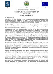
WMO / OMM<br />
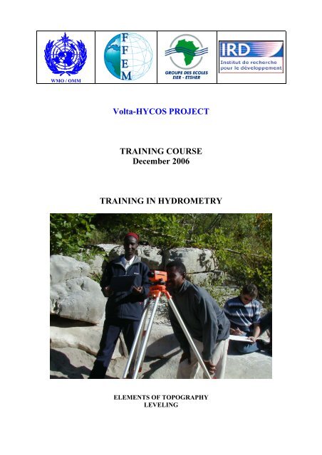
<strong>Volta</strong>-<strong>HYCOS</strong> <strong>PROJECT</strong><br />
<strong>TRAINING</strong> <strong>COURSE</strong><br />
December 2006<br />
<strong>TRAINING</strong> IN HYDROMETRY<br />
ELEMENTS OF TOPOGRAPHY<br />
LEVELING
FOREWORD<br />
This document discusses the theme of topography and leveling applied to hydrology. It is a<br />
broad and complex subject which can not be exhaustively explored in a few pages<br />
Suppplemented by notes, field visits and exchanges of experiences between participants, this<br />
document should be a good reference document for experienced or beginning hydrologists.<br />
This document, the dissemination of which is strictly limited, has been prepared from the<br />
references cited from which passages, which appear to us to be most educational, were<br />
extracted. This was complemented with the professional experience of the trainer.
SUMMARY<br />
INTRODUCTION<br />
1 LEVELING ........................................................................................................................ 3<br />
1.1 DEFINITIONS........................................................................................................... 3<br />
1.2 TRANSPORTATION ................................................................................................ 4<br />
1.3 CHECKING OF LEVEL .......................................................................................... 4<br />
1.4 PRINCIPLES OF LEVELING................................................................................... 6<br />
2 LEVELING TECHNIQUES.............................................................................................. 8<br />
2.1 PLANE LEVELING .................................................................................................. 9<br />
2.2 EXTENSION LEVELING....................................................................................... 10<br />
2.3 SURFACE LEVELING ........................................................................................... 12<br />
2.4 LONGITUDINAL SECTION.................................................................................. 13<br />
3 CLOSING......................................................................................................................... 25<br />
3.1 CALCULATION OF THE CLOSING .................................................................... 25<br />
3.2 COMPENSATION................................................................................................... 28<br />
4 CROSS SECTION ........................................................................................................... 28<br />
4.1 BENCHMARKING OF THE CHARACTERISTIC POINTS ................................ 29<br />
4.2 SLOPE OF WATER LINE ...................................................................................... 30<br />
4.3 NOTING OF A SECTION FOLLOWING AN AXIS............................................. 30<br />
4.4 SETTING OF STAFF GAUGES............................................................................. 33<br />
5 ANNEXES ....................................................................................................................... 35<br />
5.1 Station Check form................................................................................................... 35<br />
5.2 Station check form Sheet 2....................................................................................... 36<br />
5.3 Control and fixing of the staff gauges...................................................................... 37<br />
5.4 Control of distances.................................................................................................. 38<br />
5.5 Leveling notebook.................................................................................................... 39<br />
BIBLIOGRAPHICAL REFERENCES<br />
Association Française de Topographie, 2000, Lexique Topographique<br />
Brabant M., 2000, Maîtriser la topographie, M., Ed. Eyrolles<br />
D'Hollander R., 1967, Eléments de topographie, Ecole Nationale des Sciences<br />
Géographiques, Institut Géographique National.<br />
D'Hollander R., 1971, Topographie générale, tomes 1 et 2, Ed. Eyrolles.<br />
Dufour J.P., 1999, Cours d’introduction à la géodésie, Ecole Nationale des Sciences<br />
Géographiques, Institut Géographique National.<br />
Institut Géographique National, www.ign.fr<br />
Milles S. et Lagofun J., 1999, Topographie et topométrie modernes, tomes 1 et 2, Ed.<br />
Eyrolles.
Unité Observatoire Hydrologiques et Ingénierie (OBHI) IRD - Montpellier<br />
<strong>Volta</strong> – <strong>HYCOS</strong> Project Training Course on "Hydrometry"<br />
Elements of Topography – Leveling Page - 2 -
Unité Observatoire Hydrologiques et Ingénierie (OBHI) IRD - Montpellier<br />
INTRODUCTION<br />
Practical hydrometry calls for leveling techniques for numerous works: adjustment of scales,<br />
longitudinal sections and cross sectional of stations, determination of slopes of water lines,<br />
staff gage setting etc. In some cases, the results of the leveling are equally important, if not<br />
more important than the flow measurements themselves<br />
This note recalls at the same time the basic principles of leveling and should serve as a<br />
reference document to field hydrological technicians who do not have the opportunity to use<br />
surveying equipment, in order to make simple surveys of staff gage setting, longitudinal, cross<br />
and sectional profiles of hydrometric stations.<br />
The methods which are proposed and the field sheets are designed in such a way that the<br />
analysis of the data in the office can be carried out by staff other than the field personnal.<br />
The sketches proposed in this note are from Jean Thiébaux and will facilitate the<br />
understanding of the text and the practical works.<br />
1 LEVELING<br />
1.1 DEFINITIONS<br />
Topography is the art of representing on a plan the true configuration of the field.<br />
The aim of planimetry is to represent the projection, on a horizontal plan, of all the points<br />
located on the field. In this regard, one will measure the distances separating the various<br />
points from each others as well as the angles that connect these different points.<br />
Leveling or altimetry is the set of topographic operations allowing determination of the<br />
elevation of a point from the elevation of a known reference point, after having calculated the<br />
variation in level between the two points.<br />
One would distinguish the direct leveling requiring the use of a level and a sight and the<br />
indirect leveling resulting from the measurement of the vertical angle and the horizontal or tilt<br />
distance between both points.<br />
The leveling equipment (fig. 1.1) is used to generate the horizontal line of collimation and a<br />
staff for measuring the height of the different points with respect to this line of collimation.<br />
The level at A being known, one will called « back sight » or BS the reading on this point,<br />
and « front sight» or FS the reading on the staff placed on point B, which difference we want<br />
to know.<br />
The difference between the back and front sights reading gives the height between the two<br />
points A and B, if this difference is positive the point B is higher than A, if the difference is<br />
negative the point B is lower than A.<br />
The level of point B is obtained by adding algebraically the difference calculated at the level<br />
of A.<br />
<strong>Volta</strong> – <strong>HYCOS</strong> Project Training Course on "Hydrometry"<br />
Elements of Topography – Leveling Page - 3 -
Unité Observatoire Hydrologiques et Ingénierie (OBHI) IRD - Montpellier<br />
1.2 TRANSPORTATION<br />
Figure 1.1: a leveling in station<br />
The Level is a simple but however fragile instrument which must necessarily be carried in its<br />
protection box, which is itself placed in a wooden box lined with foam rubber. In the vehicle,<br />
place the box with the laid up..<br />
The staff is also very fragile and must be carried in foam rubber or thick fabric cases and<br />
especially not cantilevered with heavy objects on them.<br />
Tripods are also fragile. Avoid placing them cantilevered with heavy objects on them, ,<br />
scarping against hard objects. The layer plate must be protected by its leather cover or its<br />
original rubber cap. Avoid breaking or distorting the thumb screws.<br />
It is possible to lubricate with soap the sliding wooden parts to facilitate their slipping.<br />
1.3 CHECKING OF LEVEL<br />
An unset level generates a cone and not a horizontal plan but the results can be correct if the<br />
points sighted are at the same distance from the level. It is therefore important before<br />
beginning a reading, to set the level.<br />
In this regard, one makes a quick check by proceeding as follows: (see figure 1.2).<br />
Place two pivot boxes (see figure 1.3) or two Posts P1 and P2 at about 50 m of distance from<br />
each other.<br />
Put in station in S1 at about 50 m of P1. Read the staff placed on P1 then on P2.<br />
Let us call these readings R1 and R2 respectively. Move the level to station S2 at about 50 m<br />
of Post P2 and read the staff placed on P2 then P1. Let’s call these readings R3 and R4. The<br />
level is well adjusted and in good state if:<br />
<strong>Volta</strong> – <strong>HYCOS</strong> Project Training Course on "Hydrometry"<br />
Elements of Topography – Leveling Page - 4 -
Unité Observatoire Hydrologiques et Ingénierie (OBHI) IRD - Montpellier<br />
(R1 - R4) = (R2 - R3)<br />
Both numbers found must be equal to the nearest mm.<br />
Figure 1.2: Checking of Level<br />
Always protect the level from the sun<br />
Clean the lenses with a fine and clean handkerchief or a special<br />
optical fabric<br />
NEVER DISMANTLE AN INSTRUMENT<br />
SEND IT TO A SPECIALIST FOR FIXING IT<br />
Figure 1.3 : Topographic pivot box<br />
<strong>Volta</strong> – <strong>HYCOS</strong> Project Training Course on "Hydrometry"<br />
Elements of Topography – Leveling Page - 5 -
Unité Observatoire Hydrologiques et Ingénierie (OBHI) IRD - Montpellier<br />
1.4 PRINCIPLES OF LEVELING<br />
Topographic leveling is a survey of given points of varied elevations in a section, plane or,<br />
chainage.<br />
It consists of measuring the differences in elevation between two or more points. The<br />
principle is given in figure 1.4. It is simple but tedious, especially when measuring distances<br />
and number of important points. In this case one will use a simple or automatic level. In<br />
general in hydrology, the levelings required are cross section of a river at a given section or a<br />
longitudinal profile over 500 m across a section or also setting of staff gage to a benchmark.<br />
Figure 1.4: Leveling principle at a level<br />
<strong>Volta</strong> – <strong>HYCOS</strong> Project Training Course on "Hydrometry"<br />
Elements of Topography – Leveling Page - 6 -
Unité Observatoire Hydrologiques et Ingénierie (OBHI) IRD - Montpellier<br />
All these works are carried out with a Level. The theodolites is used by professionals. One<br />
proceeds, depending on the topography of the field and on the accessibility, by plane or by<br />
extension. (See fig. 1.5 and 1.6).<br />
Figure 1.5: Plane leveling<br />
Figure 1.6: Extension leveling<br />
<strong>Volta</strong> – <strong>HYCOS</strong> Project Training Course on "Hydrometry"<br />
Elements of Topography – Leveling Page - 7 -
Unité Observatoire Hydrologiques et Ingénierie (OBHI) IRD - Montpellier<br />
2 LEVELING TECHNIQUES<br />
The difference in level between two points (leveling) can be determined from three different<br />
processes depending on the relief, the accessibility, and the possibilities and the field<br />
conditions.(See figures 2.1, 2.2 and 2.3).<br />
1°/ The instrument is placed above one of the two points and the height Ho is measured. This<br />
height is the distance between point P1 which elevation is known and the axis of the<br />
instrument. The staff is placed vertically on the second point P2 and reading L1 is taken.<br />
The difference in level between P1 and P2 is: h = R1 - Ho<br />
Or, if one reasons in terms of elevation: Elevation of P1 + Ho - R1 = Elevation of P2<br />
Figure 2.1: Principle of leveling<br />
2°/ The instrument is placed between both points and if possible at the centre. Reading R1 is<br />
taken on the staff placed on P1 then R2 is taken on the staff placed on P2.<br />
The difference in level is: h = R2 - R1<br />
Or, if one reasons in terms of elevation: Elevation of P1 + R1 - R2 = Elevation of P2<br />
Figure 2.2 : Principle of leveling<br />
<strong>Volta</strong> – <strong>HYCOS</strong> Project Training Course on "Hydrometry"<br />
Elements of Topography – Leveling Page - 8 -
Unité Observatoire Hydrologiques et Ingénierie (OBHI) IRD - Montpellier<br />
3°/ The instrument can neither be placed on a point nor between the points. In this case one<br />
puts the level at the back or close to the points, and takes readings R1 and R2.<br />
The difference of level is: h = R2 - R1<br />
Or, if one reasons in terms of elevation: Elevation of P1 + R1 - R2 = Elevation of P2<br />
NOTE:<br />
Figure 2.3: Principle of leveling<br />
It is in the 2 nd case (station between the two staffs) that the measurement is the most precise,<br />
as residual adjustment mistakes of the instrument compensate reciprocally, provided one is at<br />
the centre of the two points. For this reason it is better to place the instrument, if possible,<br />
midway between the two staffs.<br />
2.1 PLANE LEVELING<br />
It is mainly when we make a longitudinal profile or we set a set of staff gages to a benchmark<br />
that we proceed by this method.<br />
In short, when we have a long less uneven distance to cover, it is necessary to use this method<br />
which is the fastest. (See figure 2.4). The work must be done following stages, the normal<br />
sight distance being of 50 to 60 metres (on a very uneven field, it will be shorter). But if the<br />
visibility is good, the maximum staves will be in the order of 100 m<br />
For clear staff, good lighting, moderate temperatures, it always better to work very early in<br />
the mornings.<br />
By plane, we can use stadimetric threads for measuring distances. The latter gives a work<br />
sufficiently accurate for a staff gauge setting or for a longitudinal profile (see chapter on<br />
measuring of distances).<br />
PROGRESS SPEED: 1 to 2 km/hr<br />
GIVE EQUAL SPACING BETWEEN POINTS<br />
<strong>Volta</strong> – <strong>HYCOS</strong> Project Training Course on "Hydrometry"<br />
Elements of Topography – Leveling Page - 9 -
Unité Observatoire Hydrologiques et Ingénierie (OBHI) IRD - Montpellier<br />
The staff is placed at primary point A = 1. The station of the instrument i 1 is chosen in such a<br />
way that the back horizontal sight is not above the top of the staff and that the front sight also<br />
falls on the graduation of the staff located at point 2 at a distance almost identical to the<br />
instrument. We can then take the back reading r 1 on the point of origin 1 and the front reading<br />
v 1 on spindle point 2. The instrument is then moved to i 2 . The staff remaining in place at point<br />
2 is then carefully turned so that the graduations face the new station of the instrument.<br />
Readings are then taken as previously, that is to say back reading r 2 on point 2 and front<br />
reading v 2 after the staff has been moved to point 3. Continue this way until the last front<br />
reading v 3 on point P = 4. Readings r and v are recorded in the field reports.<br />
If we need to know only the difference in level ΔH between points A and B, we just have to<br />
subtract the total of the front readings v (-4,60) from the total of back readings b (+6,50) that<br />
is to say ΔH = 6,50 – 4,60 = 1,90.<br />
Figure 2.4: Plane leveling<br />
Example of plane leveling<br />
Pt N° Back Sight r Front Sight v Notes<br />
A = 1 +2.50 r 1<br />
2 -1.80 v 1<br />
2 +0.90 r 2<br />
3 -1.90 v 2<br />
3 +3.10 r 3<br />
B = 4 -0.90 v 3<br />
+6.50 -4.60 Total<br />
-4.60<br />
ΔH +1.90 = difference of AB level<br />
2.2 EXTENSION LEVELING<br />
We proceed by extension when for practical reasons or accessibility problems, we cannot put<br />
a station between two staffs on the survey axis. This is generally the case for a staff gauge<br />
setting or cross section profiles of banks having steep slopes. (See figure 2.5).<br />
The distances between posts are then recorded horizontally at the chain.<br />
We can also do "chain and stadia" and survey the angles, but it already fall within the<br />
competence of well trained topographers. It is especially advised in the implementation of<br />
<strong>Volta</strong> – <strong>HYCOS</strong> Project Training Course on "Hydrometry"<br />
Elements of Topography – Leveling Page - 10 -
Unité Observatoire Hydrologiques et Ingénierie (OBHI) IRD - Montpellier<br />
cross section to measure all the distances between posts with a measuring tape. One uses the<br />
stadia to check cumulated distances for instance.<br />
If several sights are taken in different directions from the same station ⊗, we note in the first<br />
column of the table only the back reading, that is to say, the one taken on the staff placed at<br />
point A of elevation HA.<br />
All the other readings on the staff are placed successively on the points extended are<br />
considered as foresights and noted in the second column of the table. The elevations of these<br />
points are calculated by subtracting from the elevation of the instrument every time the front<br />
reading v from the corresponding point (HA + back reading r = 594.20); the result is noted in<br />
the third column of the table.<br />
For checking that the position of the instrument has not been change during the<br />
measurements, we finish by a new reading on the staff placed at A. It will be considered now<br />
as a front reading and by subtracting it from ⊗, we must get elevation HA.<br />
Figure 2.5 : Extension leveling<br />
Pt N°<br />
Back<br />
Elevation<br />
Sight<br />
Example of extension leveling<br />
Front Extended<br />
extension elevations<br />
Sights<br />
Notes<br />
A 592.20 Lev. point 23<br />
r 1 + 2.20<br />
⊗ 594.20<br />
v 1 - 1.80 592.40 Stone<br />
V 2 - 1.90 592.30 Boulder<br />
V 3 - 2.50 591.70 Point of rock<br />
V 4 - 2.30 591.90 Stake<br />
V 5 - 2.70 591.50 Gutter<br />
v A - 2.21 Check<br />
Α 591.99<br />
<strong>Volta</strong> – <strong>HYCOS</strong> Project Training Course on "Hydrometry"<br />
Elements of Topography – Leveling Page - 11 -
Unité Observatoire Hydrologiques et Ingénierie (OBHI) IRD - Montpellier<br />
2.3 SURFACE LEVELING<br />
To determine differences in level within a limited surface, the latter can be covered with a<br />
more or less dense network of points which elevations will be measured.<br />
When the level is correctly wedged, the telescope sight line is horizontal whatever the sight<br />
angle, (see figures 2.6 and 2.7).<br />
If height Ho of the instrument is added to the elevation of the initial point P1, we get the<br />
elevation of the sight line. By subtracting from this one the readings of staff R2 R3 etc., we<br />
get the elevation of the ground at points P2 P3 etc.<br />
Figure 2.6 : Surface measurement<br />
If we make angle surveys X1 X2 X3 and the distances between the points and the station and<br />
the points between them, the points can easily be presented in plan and the curves of levels<br />
can be traced.<br />
<strong>Volta</strong> – <strong>HYCOS</strong> Project Training Course on "Hydrometry"<br />
Elements of Topography – Leveling Page - 12 -
Unité Observatoire Hydrologiques et Ingénierie (OBHI) IRD - Montpellier<br />
2.4 LONGITUDINAL SECTION<br />
Figure 2.7: Plan survey on the curves of level<br />
A longitudinal section is generally done across a hydrometric station (figure 2.8).<br />
The distance to survey upstream and downstream of the section is in accordance with the<br />
importance of the river, its width and the slope breaking.<br />
In average and for normal cases, we indicate below the scales of size of the distances<br />
generally sufficient:<br />
− for little canals 50 m on both sides of the section<br />
− for canals of a few metres of width, 100 m on both sides<br />
− for rivers of 100 m of width, survey on 500 m upstream and 500 m downstream.<br />
− for rivers of 200 m of width, at least 1 km on both sides is necessary<br />
− for rivers of 400 m of width, survey on more than 2 km on each side of the section<br />
− As a general rule, the more the survey is long, the better it will exploitable.<br />
The main axis of the river imagined to be in spate should be followed and not the meanders<br />
of the lowest water level that winds right and left at the bottom of the mean bed. The<br />
longitudinal section is especially carried out to calculate the theoretical fall and speed at<br />
important flows and not at lowest water levels.<br />
After a flood, one follows on a bank the flood marks which perfectly reflect what the fall of<br />
the water line was during that flood. The flood marks are maximum marks left by the flood,<br />
sand, twigs, and so forth. Avoid herbs caught by flexible branches which are forcibly<br />
flattened by the speed indicating marks higher when raised.<br />
The staff man positions the staff on these very marks of the flood marks.<br />
<strong>Volta</strong> – <strong>HYCOS</strong> Project Training Course on "Hydrometry"<br />
Elements of Topography – Leveling Page - 13 -
Unité Observatoire Hydrologiques et Ingénierie (OBHI) IRD - Montpellier<br />
2.4.1 PEGS<br />
Figure 2.8 : Longitudinal section<br />
For a good leveling, the staff should rest and turn on hard spots marked off without changing<br />
elevation.<br />
To this end, pivot boxes or generally wooden posts are used.<br />
The posts should ideally be driven in the spot selected to level up to the ground and place by<br />
it a numbered sheet indicating the number of the spot (see figure 2.9).<br />
<strong>Volta</strong> – <strong>HYCOS</strong> Project Training Course on "Hydrometry"<br />
Elements of Topography – Leveling Page - 14 -
Unité Observatoire Hydrologiques et Ingénierie (OBHI) IRD - Montpellier<br />
2.4.2 SETTING UP<br />
Figure 2.9 : Posts and benchmarks<br />
The setting up of a level should be rapid and correct. To achieve the fixing, it is necessary to<br />
always proceed the same way and in the same order.<br />
Before fixing the equipment on its layer plate, ensure that support surfaces are soil or sand<br />
free.<br />
The telescopic tripod is totally or partially extended so as to position the layer plate at the<br />
level of the chin in normal standing position.<br />
The tips which are made of steel are driven in the ground by pressing with the foot.<br />
Repeatedly press with feet when on light soil. The layer plate is almost horizontally set by<br />
adjusting the sliding stands of the tripod.<br />
Position then the field glass parallel to the two micrometer screws the leveller towards<br />
oneself. (Figure 2.10 Position I). By simultaneously turning the two screws 1 and 2 (at the<br />
same time) and always in the same direction one opposed to the other, that is by a<br />
simultaneous in and out movements of the two thumbs, the spherical bubble is brought in the<br />
axis perpendicular to the field glass.<br />
<strong>Volta</strong> – <strong>HYCOS</strong> Project Training Course on "Hydrometry"<br />
Elements of Topography – Leveling Page - 15 -
Unité Observatoire Hydrologiques et Ingénierie (OBHI) IRD - Montpellier<br />
Figure 2.10: Setting up of the Position 1 level<br />
The field glass is made to pivot at a right angle (90°) directed towards the screw 3 (Figure<br />
2.10 Position II) and the bubble is brought to its position by uniquely operating on screw 3.<br />
With little experience, this is enough to fix the level correctly. Otherwise, come back to<br />
position I and continue the same operation, field glass parallel to screws 1 and 2, always<br />
perfecting the fixing on the two screws at the same time and in opposite direction and come<br />
back to position II at 90° and position correctly the bubble in the central circle of the leveller<br />
by operating only the screw 3.<br />
Figure 2.10: Setting up of the Position 2 level<br />
<strong>Volta</strong> – <strong>HYCOS</strong> Project Training Course on "Hydrometry"<br />
Elements of Topography – Leveling Page - 16 -
Unité Observatoire Hydrologiques et Ingénierie (OBHI) IRD - Montpellier<br />
The setting could be impossible if the layer plate is too much tilted, the setting of the fixing<br />
screws is insufficient or if some fixing screws are blocked.<br />
2.4.3 SETTING OF THE SIGHTING<br />
With the level and staff in position, what is needed is performing the required readings. The<br />
settings are a little bit different for the different types of equipment used, but are generally of<br />
the same kind. Rough sighting of the staff with the foresight above the field glass of the rifle<br />
type is obtained. The sharpness of the reticles is then set once and for all. These settings vary<br />
according to the sight of the operator. The reticles are cross wires seen through the field glass.<br />
The sighting wires that should be set very sharp and deep black. There is generally one<br />
vertical wire and 3 horizontal wires, with a longer middle wire or with V on the left side (see<br />
figure 2.11).<br />
The sharpness of the picture is then adjusted on the staff as with binoculars by operating on a<br />
side screw which is generally bigger than the others.<br />
Before each reading, some equipments require a setting of the coincidence bubbles or a<br />
pressing of a button in order to check the suspension of the primes (case of automatic levels).<br />
Follow specific indications for each type of equipment.<br />
The subtle and lateral crabbings of the field glass to bring the reticles on the staff at the best<br />
wished position in order to facilitate readings are done with the help of a button generally<br />
located in the front side of the equipment.<br />
Figure 2.11 : Setting of the sharpness<br />
2.4.4 READINGS AND CHECKING<br />
It is strongly advised to systematically take the three readings and write them down. That is a<br />
reading corresponding to the UPPER line, a reading for the MIDDLE and a reading for the<br />
LOWER.<br />
A checking is immediately carried out in order to avoid mistakes by performing the<br />
following:<br />
Reading of the UPPER<br />
Reading of the MIDDLE<br />
- Reading of the MIDDLE - Reading of the LOWER<br />
= x = x<br />
<strong>Volta</strong> – <strong>HYCOS</strong> Project Training Course on "Hydrometry"<br />
Elements of Topography – Leveling Page - 17 -
Unité Observatoire Hydrologiques et Ingénierie (OBHI) IRD - Montpellier<br />
The two differences should be equal, or differ by 2 or 3. We could also have UPPER +<br />
LOWER= MIDDLE x 2 which amounts to the same thing, but perhaps less simple. Use the<br />
formula that suits you most.<br />
2.4.4.1 EXAMPLE :<br />
Reading of the UPPER 1553<br />
Reading of the MIDDLE 1357<br />
Reading of the LOWER 1160<br />
2.4.4.2 CHECKS :<br />
Or :<br />
- 1553 - 1357<br />
1357 1160<br />
196 = 197<br />
2.4.4.3 DESIGNATION<br />
1357 1357 1553<br />
+ 1357 x 2 + 1160<br />
2714 2714 = 2713<br />
Generally, points where the leveling instrument has been positionned are called Stations. It is<br />
preferrable to call them in the order of progress, that is S1 S2 S3, etc.<br />
The points levelled with the staff could be called anyhow, but in a way that they could be<br />
easily recognized. Generally P1 P2 P3, etc. but also B0, B1, B2 for the benchmarks or else<br />
US1 which may mean Upper at Scale 1. The main thing is for the operator to find his way<br />
during the review.<br />
The points generally have the same number during all the leveling, for instance: P3 for the<br />
going and P18 for the return. It is still P3. If the longitudinal section goes through a post of<br />
the cross section, the post will bear the same name on the two sections. Likewise, we will not<br />
of course find two times the same designation on the two various points.<br />
In traditional leveling, the "FORE SHOTS" are those that are aimed at forward. "BACK<br />
SHOTS" are obviously those that are read through the field glass when looking back towards<br />
where we are coming from. The fore shots are calculated using negative values and the back<br />
shots with positive values. (See chapter on CLOSING).<br />
2.4.5 ELEVATION<br />
The ABSOLUTE elevation (see figure 2.12), is the actual elevation of a land mark in relation<br />
to an official leveling GL (General Leveling) which covers the whole country and starts with<br />
mean sea level. All levelled points or points deducted from that origin are then absolute<br />
levels.<br />
Whenever it is possible to relate to a GL benchmark, that is the known REAL absolute<br />
elevation, it is preferable to do so.<br />
<strong>Volta</strong> – <strong>HYCOS</strong> Project Training Course on "Hydrometry"<br />
Elements of Topography – Leveling Page - 18 -
Unité Observatoire Hydrologiques et Ingénierie (OBHI) IRD - Montpellier<br />
The assumed elevation (see figure 2.13), is a fictitious "invented" elevation that is imposed on<br />
a « starting » benchmark and from which all other elevations will be deducted. It is advised to<br />
attribute a starting point an assumed elevation of 50, 000 m to a main benchmark of the<br />
station. This will allow for marking all points as longitudinal sections, cross sections, scales,<br />
flood marks and even gauging points. These imaginary elevations could be converted<br />
automatically into absolute elevations when the main benchmark is related to the GL.<br />
Figure 2.12: Absolute elevation<br />
<strong>Volta</strong> – <strong>HYCOS</strong> Project Training Course on "Hydrometry"<br />
Elements of Topography – Leveling Page - 19 -
Unité Observatoire Hydrologiques et Ingénierie (OBHI) IRD - Montpellier<br />
Figure 2.13: Assumed elevation<br />
<strong>Volta</strong> – <strong>HYCOS</strong> Project Training Course on "Hydrometry"<br />
Elements of Topography – Leveling Page - 20 -
Unité Observatoire Hydrologiques et Ingénierie (OBHI) IRD - Montpellier<br />
2.4.6 THE STAFF<br />
The positionning of the staff is done with wide opened feet and supporting oneself on the<br />
front with the eyes fixed on the leveller.<br />
It is the only means to facilitate readings, especially if there is wind. (See figure 2.14).<br />
In order not to unnecessarily exhaust the staff man, it is agreed with him to always work with<br />
same « signs » to be able to “tell” him, moving, reading, end of reading, go left, go right, go<br />
back; forward, climb, come down etc.<br />
Never leave the staff under the sun during a break or position it in a manner that is not<br />
appropriate.<br />
From time to time, it is necessary to check the that the level is correctly set on the staff. To do<br />
this, the staff should be perfecly positioned at vertical position, in all direction with a level as<br />
with a plumb line and the bubble is brought in the circle of the leveller with the help of 3<br />
setting crews located in the cage of he leveller. Then block the central screw with the central<br />
screw.<br />
If the staff changes postition, the station should keep its position. If the station (the level)<br />
must be moved the staff should remain on its position and only turned round.<br />
THE STAFF AND THE LEVEL SHOULD NOT BE SEEN MOVED AT<br />
THE SAME TIME.<br />
Figure 2.14 : The staff<br />
<strong>Volta</strong> – <strong>HYCOS</strong> Project Training Course on "Hydrometry"<br />
Elements of Topography – Leveling Page - 21 -
Unité Observatoire Hydrologiques et Ingénierie (OBHI) IRD - Montpellier<br />
2.4.7 THE MEASUREMENT OF DISTANCES<br />
As it has already been mentionned in the chapter LEVELING BY RADIATION distances can<br />
be measured using either the surveying chain or the STADIA.<br />
Beware of the "inverted" chain and never measure along the slope, which is wrong, but<br />
always in horizontal position (see figure 2.15).<br />
Figure 2.15 : Measuring of distance<br />
The stadia measuring gives the distance between the level (the station) and the staff. This<br />
measurement is not very precise but generally adequate for hydrological surveys.<br />
The distance between the level and the staff is equal to the Reading of the UPPER line –<br />
reading of the LOWER line multiplied by a constant K. K is a coefficient used following the<br />
works in order to have a practical and representative measuring unit, generally the meter and<br />
as a function of the deflection of the reticles. Generally the reticles of the levels have a<br />
deflection of the stadimetric wires of 1 per 100, that means that if we read on the UPPER line<br />
3485 and on the LOWER line 3170 the distance between the level and the staff is :<br />
3485 - 3170 = 315 mm<br />
315 mm x k = 315 x 100 = 3150 mm = 31,5 m<br />
(If k = 100) to be confirmed.<br />
On some types of equipment, it can be equal to 0.3: 100.<br />
In practice we take K = 10 to divide by the reading to obtain meters, that is:<br />
315 / 10<br />
3485 - 3170 = _______ gives 31.5 m<br />
10<br />
<strong>Volta</strong> – <strong>HYCOS</strong> Project Training Course on "Hydrometry"<br />
Elements of Topography – Leveling Page - 22 -
Unité Observatoire Hydrologiques et Ingénierie (OBHI) IRD - Montpellier<br />
2.4.8 CICRLES AND MEASUREMENT OF ANGLES<br />
The measurement of angles are done on the circle, either in radians or in degrees. This should<br />
be specified in the observations column. A circle graduated in radians is divided into 400 for<br />
one complete rotation and into 360 if graduated in degrees.<br />
The subdivisions of the radians are of 1/10 or 1/100 and the subdivisions of the degrees are<br />
minutes. (60 minutes for 1 degree). The systems and the graduations for different types of<br />
equipment vary a lot.<br />
We reproduce the main Levels which are generally used by hydrologists in various sketches<br />
in the figures 2.16 to 2.19).<br />
Figure 2.16: WILD NK01 Level<br />
Figure 2.17: Measurement of an angle on a KERN GK23 level<br />
<strong>Volta</strong> – <strong>HYCOS</strong> Project Training Course on "Hydrometry"<br />
Elements of Topography – Leveling Page - 23 -
Unité Observatoire Hydrologiques et Ingénierie (OBHI) IRD - Montpellier<br />
The angles are recorded when it is necessary to reproduce in a plan, the exact positions of the<br />
levelled points in addition to their elevations.<br />
Figure 2.18 : Measurement of an angle on a WILD NK2 level<br />
Figure 2.19 : : Measurement of an angle on a ZEISS NI2 level<br />
<strong>Volta</strong> – <strong>HYCOS</strong> Project Training Course on "Hydrometry"<br />
Elements of Topography – Leveling Page - 24 -
3 CLOSING<br />
Unité Observatoire Hydrologiques et Ingénierie (OBHI) IRD - Montpellier<br />
The closing is the fact of ending one’s leveling on a point, the elevation of which is known.<br />
This is done by eiither coming back to the starting point, or going to another benchmark<br />
already levelled and therefore of known elevation.<br />
It is the only way to check whether the whole leveling is good and to evaluate its accuracy.<br />
CLOSING IS COMPULSORY<br />
Example: if one starts a leveling at the point P1, attributing to it an assumed elevation of<br />
50,000 m. After having completed the required layout, one comes back to the point P1. It is<br />
obvious that the calculations should lead to an elevation of 50,000 m at the end, with only a<br />
deviation of a few centimetres or millimetres depending on the required accuracy.<br />
Supposing we start on a macaroon NG which has for instance a known elevation of 367, 630<br />
m and that we end on another NG benchmark, the elevation of which is for instance 388,302<br />
m, it is obvious that starting the review at 367,630 we should finish at 388,302 or<br />
somewhere around that figure.<br />
If this is not the case one or several reading mistakes have been made during the leveling or in<br />
the calculations.<br />
The checking of the closing should be done in the field in order to avoid travel in the event of<br />
mistake, especially when working far from one’s base.<br />
To facilitate the activities of checking of the closing, it is advised to position on the stations<br />
several stable benchmarks on the two banks, at the level of the staff gauge section, or gauging<br />
section by boat, etc. These benchmarks should be linked to each other and their known<br />
elevations known and recorded in the station file. The field teams should have a copy when<br />
visiting the station.<br />
3.1 CALCULATION OF THE CLOSING<br />
The calculation of the closing is simple and quick. It consists of carrying out a series of<br />
additions and subtractions.<br />
We start by posing the elevation of the starting point, for instance 50.00m to which we add<br />
the reading of the MIDDLE of the staff on this point P1 for instance 2, 864. This is the<br />
assumed elevation of the line of sight of the station 1 (see figure 3.1). Then we subtract from<br />
this elevation the MIDDLE reading recorded on the staff of the last point read from the station<br />
1, for instance 3, 605. This gives 49, 259 the assumed elevation of the point 5. The<br />
intermediate sightings on the points P2 P3 P4 are not reviewed on the field.<br />
Continuing in the same way 49,259 + MIDDLE reading read from S2 the staff turned towards<br />
P5 will give the elevation of the line of sight of S2 from which if the reading of P8 is<br />
subtracted, will give the elevation of P8 etc. (It will always be + - + - + -).<br />
<strong>Volta</strong> – <strong>HYCOS</strong> Project Training Course on "Hydrometry"<br />
Elements of Topography – Leveling Page - 25 -
Unité Observatoire Hydrologiques et Ingénierie (OBHI) IRD - Montpellier<br />
Figure 3.1 : Progression and Closing<br />
<strong>Volta</strong> – <strong>HYCOS</strong> Project Training Course on "Hydrometry"<br />
Elements of Topography – Leveling Page - 26 -
Unité Observatoire Hydrologiques et Ingénierie (OBHI) IRD - Montpellier<br />
Making for instance (figure 3.1).<br />
50.000 elevation P1 starting<br />
2.864 MIDDLE reading the staff on P1 observed from S1<br />
52.864 elevation line of sight of S1<br />
3.605 MIDDLE reading the staff on P5 observed from S1<br />
49.259 elevation of P5<br />
1.007 MIDDLE reading the staff on P5 observed from S2<br />
50.266 elevation line of sight of S2<br />
2.888 Reading of staff on P8 observed from S2<br />
47.378 elevation of P8<br />
3.964 reading of staff on P8 observed from S3<br />
51.342 elevation of S3<br />
0.642 reading of staff on P13 observed from S3<br />
50.700 elevation of P13<br />
3.025 reading of staff P13 observed from S4<br />
53.725 elevation of S4<br />
3.722 reading on P1 observed from S4<br />
50.003 elevation of P1 reached at closing<br />
We can see that the closing is at 3 mm which is very acceptable.<br />
Another method generally used by professionals consists of adding the “FORESIGHTS » and<br />
the « BACKSIGHTS » and subtract the difference. In the example chosen we have:<br />
BACKSIGHTS<br />
FORESIGHTS<br />
+ -<br />
2864 3605<br />
1007 2888<br />
3964 0642<br />
3035 3722<br />
= 10860 = 10857<br />
10860 - 10857 = + 00003 An acceptable Closing.<br />
If we proceed from a benchmark of known elevation (P1 for instance 389,064 m) and that we<br />
close on another elevation benchmark equally known (for example 389,761 for P13 on the<br />
figure 3.1) we can proceed in two different ways :<br />
<strong>Volta</strong> – <strong>HYCOS</strong> Project Training Course on "Hydrometry"<br />
Elements of Topography – Leveling Page - 27 -
Unité Observatoire Hydrologiques et Ingénierie (OBHI) IRD - Montpellier<br />
(1) (2)<br />
ou<br />
389,064<br />
2.864 + -<br />
391.928<br />
3.605 2864 3605<br />
388.323 1007 2888<br />
1.007 3964 0642<br />
389.330 = + 7835 = - 7135<br />
2.888<br />
386.442<br />
+ 3.964 389.064<br />
390.406 + 7.835<br />
- 0.642 396.899<br />
389.764 - 7.135<br />
= 389.764<br />
For 389,761 official quotation of P13 we find 389.764 giving also an error of 3 mm.<br />
The method (1) is advisable for the current leveling works in hydrology. It helps to rapidly<br />
carry out the closing checks in the field by making a good differentiation of the points of<br />
progression and of radiation. It is necessary that a field team imperatively check the closing of<br />
its leveling and to restart the portions that are wrong before coming back to the office.<br />
3.2 COMPENSATION<br />
During precision leveling , it is necessary to carry out « the compensation difference » by<br />
distributing evenly « the closing difference » on all levelled points.<br />
4 CROSS SECTION<br />
Theoretically cross sections are carried out as longitudinal sections with radiated points in<br />
addition. The particularities of this require that some methodological rules that will help avoid<br />
the most common errors be respected. The carrying out of the cross section at a station which<br />
has a water flow on the right side that forbids fording, implies the section be divided into<br />
three parts: The Left Bank, the section of wetted area, and the Right bank.<br />
If the section is carried out at the right of the staff gauges, the work is started from a fixed<br />
benchmark. It is convenient to extend the section on the banks to the possible flooded area.<br />
The work is greatly facilitated if the section at the right of the staff gauges has been marked<br />
out by two markers on RB and LB the elevation of which are known. In this case, the portions<br />
of section could be dealt with separately and finally be carried out by two different teams.<br />
The leveling of the cross section includes two distinctive operations, the one allowing for the<br />
calculation of distances between characteristic points of the section and the other for the<br />
determination of the elevations of these points. In the first place it is essential to carry out a<br />
freehand drawing on the field sheet of distances. These sketches will allow for siting the<br />
points, ones in relation to the other.<br />
<strong>Volta</strong> – <strong>HYCOS</strong> Project Training Course on "Hydrometry"<br />
Elements of Topography – Leveling Page - 28 -
Unité Observatoire Hydrologiques et Ingénierie (OBHI) IRD - Montpellier<br />
4.1 BENCHMARKING OF THE CHARACTERISTIC POINTS<br />
This operation must be carried out with wooden pegs which can possibly be made on the spot<br />
and on which numbers can be written with a felt-tip marker. The order of numbering has no<br />
importance. These pegs must be placed at places which are typical of the section. They will<br />
serve as markers and the staff will be placed nearby, on the ground for extended point and on<br />
a pivot box for planed points.<br />
Do not forget to place a benchmark at the level of the water mark on both banks.<br />
4.1.1 Partial measurements of distances<br />
Once benchmarking is finished, one can measure the partial distances between the<br />
benchmarks. The results are recorded on the NICD distance field sheet. In relatively flat<br />
sections, it is possible to leave the tape measure in place and make cumulated readings. The 4<br />
columns on the right of the sheet allow for all the combinations.<br />
4.1.2 Specific case of the wet section<br />
If the width of the river allows it, one uses a measuring tape, stretch between both banks of<br />
which the 0 has been placed at the level of the first benchmark which marks the border of the<br />
bank water. If the width is too wide it is necessary to use the gauging cable.<br />
4.1.3 Check of distances.<br />
If the distance is not too large, and if the level used allows it, it is recommended to check the<br />
distances with the stadia between two benchmarks located on both banks which are almost at<br />
the same elevation. Compare these results with those of the accumulations obtained by adding<br />
the partial distances. This checking allows for detecting thesignificant mistakes.<br />
4.1.4 Leveling of all the points outside water<br />
This operation is carried out with the level. It is recommended to begin at the boundary marks<br />
with known elevation. For rivers which are not too large it is possible to level the points<br />
located on both banks at the same time from station. It is necessary to have in that regard both<br />
staffs. This technique saves time.<br />
It is important to take a reading on the staff gauge at the time of the measurement and note the<br />
reading on the staff. This measurement will allow for checking the wedging of the wet<br />
section.<br />
4.1.5 Sounding the wet section.<br />
If the section is too deep one will use a boat. The depths will be determined with the staff and<br />
the level if the depths do not exceed 2 metres. If more, one will take the depth from the<br />
surface always with the staff. If the depth exceeds 3 m one will use a winch and a sounding<br />
weight.<br />
Closures are calculated from chimneys points. If the section has been organised in sections<br />
with return on boundary marks, one will carry out a check by section. If a mistake occurred,<br />
only the section affected will be made repeat.<br />
<strong>Volta</strong> – <strong>HYCOS</strong> Project Training Course on "Hydrometry"<br />
Elements of Topography – Leveling Page - 29 -
Unité Observatoire Hydrologiques et Ingénierie (OBHI) IRD - Montpellier<br />
4.2 SLOPE OF WATER LINE<br />
This operation is carried out in general during or after a flooding. It allows the determination<br />
of the driving slope in the reach. This slope will serve for determining the value of the K<br />
coefficient of STRICKLER formula if a complete gauging has been done at the same time. If<br />
this measurement is related to an exceptional non-gauged flooding, it allows for extrapolation<br />
from the rating curve with precision.<br />
This type of work can be assimilated globally to the implementation of a longitudinal section.<br />
Some precautions must be taken in the methodology and in the implementation.<br />
4.2.1 During flooding<br />
It is important to quickly benchmark the points to be levelled on upstream and downstream<br />
sides of the staff. Count on average 500 m upstream and downstream. Read the staff gauge at<br />
the beginning, at the middle and at the end of the benchmarking. This operation must be<br />
quickly carried out to too much variation in staff readings. If the opposite bank is reachable it<br />
is interesting to carry out the same operation on the second bank or at least mark out some<br />
points.<br />
Level the points marked out not forgetting to place the staff on a pivot box which will be the<br />
same model at all the points. Carry out staffs of 50m maximum. This corresponds to a<br />
progression of 100m per sights. It is possible to also sight extended points. Organise the<br />
progress to level the points by going and returning and not passing twice on the same<br />
benchmark.<br />
If the banks are overgrown with plants, it is often easier to level the points from the opposite<br />
bank if the section is not too large.<br />
Closures must be good. The order of variations of height to expect is one metre over 1000M<br />
(i= 1/1000) over a distance of 1km.<br />
4.2.2 After flooding<br />
In this case, one tries to determine the slope of the water line which corresponds to the<br />
maximum level of the water swelling. This level is obtained in the field by a portion of the<br />
foreshores of water marks which are visible. This marking is clear when the flooding is<br />
recent.<br />
The methodology is the same for the previous case but we have more time for benchmarking.<br />
It is recommended to immediately note the section on paper to be sure that the flood marks<br />
have been marked out corresponding to the same flooding. In fact, as the water level<br />
decreases, flood marks can appear at various levels.<br />
4.3 NOTING OF A SECTION FOLLOWING AN AXIS.<br />
Noting a section following an axis is generally represented under the form of a vertical<br />
section of the ground following this axis. In the Y axis, we find elevations and in abscissa the<br />
distances.<br />
<strong>Volta</strong> – <strong>HYCOS</strong> Project Training Course on "Hydrometry"<br />
Elements of Topography – Leveling Page - 30 -
Unité Observatoire Hydrologiques et Ingénierie (OBHI) IRD - Montpellier<br />
It would be preferable to use the same scale for differences in levels (elevations) and for<br />
distances but this often leads to less practical presentation formats and we are compelled to<br />
use a disproportioned graph, which is always less representative.<br />
It is often useful to note at the bottom the partial distances, accumulated distances, etc. (see<br />
figure 4.1).<br />
Figure 4.1: Cross-sectional of a measurement section<br />
One notes that the staffs must be placed at each break or important slope changes if we want<br />
to correctly apprehend the layout. This is very important. One notes for example on figure<br />
4.2 purposely exaggerated, that if B7 and B8 had not been there, one would had laid out<br />
directly from B6 and B9 of which is misleading. And as B4 and B6 without B5 or B9 and B12<br />
without B10 and B11.<br />
On the opposite, between B12 and B13 if the slope is regular it is not useful to take<br />
intermediary points.<br />
In short, between two staff benchmarks or positions, the ground where the surface presents<br />
really a strait line either horizontal or vertical being of any slope constant and regular.<br />
Any important level modification must be subject to a levelled point.<br />
4.3.1 GENERALITIES<br />
We will remind in this chapter some generalities to observe by necessity, obligation,<br />
normalisation within the Hydrologic Department.<br />
X = sense of flow. Longitudinal section of the river upstream downstream. Speed.<br />
Y = sense perpendicular to the flow. Gauge section. Cross-section. Width.<br />
<strong>Volta</strong> – <strong>HYCOS</strong> Project Training Course on "Hydrometry"<br />
Elements of Topography – Leveling Page - 31 -
Unité Observatoire Hydrologiques et Ingénierie (OBHI) IRD - Montpellier<br />
Z = height, vertical sense, measures depth and verticals. Whatever, the staff must only swivel<br />
on a hard point (pivot box or benchmark), without changing elevation.<br />
Sketches on the leveling report are requested.<br />
Write with a pencil if possible.<br />
It is advisable to always have 2 sharpened pencils tied to a string and a pencil sharpener or a<br />
knife.<br />
Use a plane table with a string around the back and clips or elastic bands (tube strap) to hold<br />
the sheets or the report book.<br />
A compass and a map are also useful.<br />
4.3.2 LEVELING NOTE BOOK<br />
Figure 4.2 : Examples of topographic surveys<br />
Here are some principal indications of the way to keep a model leveling report book.<br />
Nr. OF STATIONS<br />
In this column one notes the numbers of stations as the work progress as order P1, P2, P3, etc.<br />
Nr. OF BENCHMARKS<br />
Note in this column the numbers or names of boundary marks, benchmarks or various points<br />
on which the staff is laid and therefore the points which fictive or absolute elevation we want<br />
to know. We shall always note for example Mo M1 B1 B2 B3 etc in the progress order of<br />
sights.<br />
DISTANCES BETWEEN BENCHMARKS<br />
In each box, will be noted the real, horizontal, partial distance, between both benchmarks<br />
(corresponding to the accolade) measured with a chain or a pentadecameter. Make sketches<br />
on the right page.<br />
READINGS<br />
One notes the three readings which correspond to the three reticules TOP - MIDLLE -<br />
BOTTOM.<br />
<strong>Volta</strong> – <strong>HYCOS</strong> Project Training Course on "Hydrometry"<br />
Elements of Topography – Leveling Page - 32 -
Unité Observatoire Hydrologiques et Ingénierie (OBHI) IRD - Montpellier<br />
CHECK<br />
One immediately checks readings by making the substraction (TOP – MIDLLE) which must<br />
not differ by more than 2 or 3 mm from (MIDLLE-BOTTOM).<br />
ELEVATIONS OF STAFF LINES<br />
The elevation of the line of sight is the actual or assumed elevation of the mean sea level seen<br />
through and within the telescope axis.<br />
If a staff is placed on a benchmark whose elevation is 50 m and that the MIDDLE reading<br />
seen through the telescope indicates 1561, this means that the elevation of the line of sight is<br />
at 51,561 m.<br />
ELEVATIONS OF BENCHMARKS<br />
From the elevation of a starting point and the elevations of line of sight one can deduce the<br />
elevations of all the levelled points.<br />
SKETCHES AND OBSERVATIONS<br />
One must find on this page all the sketches and information necessary for a good<br />
understanding of the work done and especially of reporting.<br />
4.4 SETTING OF STAFF GAUGES<br />
This column gives details of the operations to be undertaken to check that the staff gauges are<br />
in position. Before moving the staff gauges elements, it is necessary to note with precision the<br />
shift for correcting, if necessary, the previous readings.<br />
4.4.1 Set of operations to carry out at each station:<br />
1. Make the plan of the installations.<br />
2. Clear the section at the level of the boundary mark scales.<br />
3. Make the ½ freehand section at the level of scales by indicating all the details. Specify<br />
the types of supports for each element, the location and the type of boundary marks.<br />
4. Make the leveling going from the boundary mark and returning to the same boundary<br />
mark. This work must be carried out prior to any resetting.<br />
Use a leveling sheet to indicatie that it is the measurement as it is.<br />
5. Make the calculation on the leveling sheet and determine the elevations of all the staff<br />
gauges in the elevation system of the boundary mark. These calculations can be done<br />
only if the closure control is correct (3 mm maximum). If this closure is more to 3<br />
mm, the leveling must be repeated.<br />
6. Determine the values of the first reference column of NICE1 form.<br />
Elevation of the boundary mark:<br />
If this elevation is known, use this slide; if not given an assumed elevation of 20 000<br />
to 50,000 m<br />
Wedging of the «0» – indicates here the «O» level in connection with the boundary<br />
mark. This indication is on the station forms and results from the first leveling prior to<br />
the establishment of the staff gauges. This value is often expressed as negative,<br />
example «0» scale= -5.63.<br />
<strong>Volta</strong> – <strong>HYCOS</strong> Project Training Course on "Hydrometry"<br />
Elements of Topography – Leveling Page - 33 -
Unité Observatoire Hydrologiques et Ingénierie (OBHI) IRD - Montpellier<br />
Z of «0»: this value is the elevation of «0» in the boundary mark system.<br />
Example<br />
Z boundary mark = 50.000 m<br />
Wedging «0» = -5.63<br />
Z «0» = 50.000 – 5.630 = 44.37 m<br />
In the first column « Theoretical Z »<br />
Calculate the elevation of the top of the element; example in the previous case<br />
Z «0» = 44.37<br />
Theoretical Z top of the element 0 – 1 m: 44.37 –1.00 = 43.37 m<br />
Indicate the reference elevations of all the elements visible or not on the day of the<br />
checking.<br />
7. From the results of the leveling of the scales which have just been made, note in the<br />
first column of the following group «before rectification » Z of checking, the value of<br />
the elevations of the tops of all the staff gauges levelled.<br />
Compare these elevations with the reference one, determine the differences.<br />
8. Re-establish the staff gauges which have been dislodged using the values of those<br />
inplace.<br />
9. Make a leveling of check of the first operation on a different sheet if necessary.<br />
10. Report the results of elevations of this check in the third column of the NICE1 field<br />
form<br />
4.4.2 Summary<br />
For each station, we must have:<br />
1 form NS01<br />
1 form NS02<br />
1 form NICE1<br />
2 forms NI00<br />
If necessary various sketches help explain the levelings.<br />
If the station has no bench marks:<br />
1. Establish a bench mark and make a stable point in concrete.<br />
2. Carry out all the operations described for checking the staff gauges from 1 to 6<br />
and from the elevations of the « Z check » column; try to find the former<br />
possible shift by similarity.<br />
<strong>Volta</strong> – <strong>HYCOS</strong> Project Training Course on "Hydrometry"<br />
Elements of Topography – Leveling Page - 34 -
Unité Observatoire Hydrologiques et Ingénierie (OBHI) IRD - Montpellier<br />
5 ANNEXES<br />
5.1 Station Check form<br />
STATION: RIVER: N° National :<br />
DATE N° HYDROM : H= Time:<br />
READER:<br />
Distance Habitation Scale :<br />
Substitute:<br />
ADRESS:<br />
Reading Instructions<br />
Readings check<br />
PLAN OF THE INSTALLATIONS<br />
<strong>Volta</strong> – <strong>HYCOS</strong> Project Training Course on "Hydrometry"<br />
Elements of Topography – Leveling Page - 35 -
Unité Observatoire Hydrologiques et Ingénierie (OBHI) IRD - Montpellier<br />
5.2 Station check form Sheet 2<br />
Station :<br />
FREEHAND DRAWING OF THE BANK WITH STAFF GAUGES AND BENCH MARKS<br />
COMMENTS<br />
<strong>Volta</strong> – <strong>HYCOS</strong> Project Training Course on "Hydrometry"<br />
Elements of Topography – Leveling Page - 36 -
Unité Observatoire Hydrologiques et Ingénierie (OBHI) IRD - Montpellier<br />
5.3 Control and fixing of the staff gauges<br />
STATION : RIVER : N° National :<br />
N° HYDROM: OPERATOR :<br />
ALT. of MARKER: FIXING of the“0” = Z of “0” =<br />
REFERENCES Before correction After correction OBSERVATIONS<br />
Upper<br />
Element<br />
n°<br />
Theoretic<br />
al Z<br />
Control Z<br />
Difference<br />
Control Z<br />
Difference<br />
Observations<br />
COMMENTS:<br />
<strong>Volta</strong> – <strong>HYCOS</strong> Project Training Course on "Hydrometry"<br />
Elements of Topography – Leveling Page - 37 -
Unité Observatoire Hydrologiques et Ingénierie (OBHI) IRD - Montpellier<br />
5.4 Control of distances<br />
CONTROL OF DISTANCES<br />
DISTANCES<br />
POST N° SIGHTING POST N° SIGHTING<br />
DISTANCE MEASURED<br />
WITH TAPE MEASURE<br />
FRO<br />
M<br />
to<br />
DISTAN<br />
CE<br />
m<br />
cm<br />
DISTANCE<br />
SKETCH<br />
DISTANCE<br />
DIFFERENCE =<br />
<strong>Volta</strong> – <strong>HYCOS</strong> Project Training Course on "Hydrometry"<br />
Elements of Topography – Leveling Page - 38 -
Unité Observatoire Hydrologiques et Ingénierie (OBHI) IRD - Montpellier<br />
5.5 Leveling notebook<br />
<strong>Volta</strong> – <strong>HYCOS</strong> Project Training Course on "Hydrometry"<br />
Elements of Topography – Leveling Page - 39 -