

A Variable-Impedance Prosthetic Socket for a Transtibial Amputee ...
A Variable-Impedance Prosthetic Socket for a Transtibial Amputee ...
A Variable-Impedance Prosthetic Socket for a Transtibial Amputee ...

Create successful ePaper yourself
Turn your PDF publications into a flip-book with our unique Google optimized e-Paper software.
A <strong>Variable</strong>-<strong>Impedance</strong> <strong>Prosthetic</strong> <strong>Socket</strong> <strong>for</strong> a <strong>Transtibial</strong><br />
<strong>Amputee</strong> Designed from Magnetic Resonance<br />
Imaging Data<br />
David Moinina Sengeh, MS, Hugh Herr, PhD<br />
ABSTRACT<br />
This article evaluates the design of a variable impedance prosthetic (VIPr) socket <strong>for</strong> a transtibial amputee using computeraided<br />
design and manufacturing (CAD/CAM) processes. Compliant features are seamlessly integrated into a three-dimensional<br />
printed socket to achieve lower interface peak pressures over bony protuberances by using biomechanical data acquired<br />
through surface scanning and magnetic resonance imaging techniques. An inverse linear mathematical trans<strong>for</strong>mation<br />
spatially maps quantitative measurements (bone tissue depth) of the human residual limb to the corresponding prosthetic<br />
socket impedance characteristics. The CAD/CAM VIPr socket is compared with a state-of-the-art prosthetic socket of similar<br />
internal geometry and shape designed by a prosthetist using conventional methods. An active bilateral transtibial male<br />
amputee of weight 70 kg walked on a <strong>for</strong>ce plateYembedded 5-m walkway at self-selected speeds while synchronized ground<br />
reaction <strong>for</strong>ces, motion capture data, and socket-residual limb interface pressures were measured <strong>for</strong> the evaluated sockets.<br />
Contact interface pressure recorded (using Teksan F-<strong>Socket</strong>i pressure sensors) during the stance phase of several completed<br />
gait cycles indicated a 15% and 17% reduction at toe-off and heelstrike, respectively, at the fibula head region while the<br />
subject used a VIPr socket in comparison with a conventional socket of similar internal shape. A corresponding 7% and 8%<br />
reduction in pressure was observed along the tibia. Similar trends of high-pressure reductions were observed during quiet<br />
single-leg standing with the VIPr socket in comparison with the conventional socket. These results underscore the possible<br />
benefits of spatially varying socket wall impedance based upon the soft tissue characteristics of the underlying residual limb<br />
anatomy. (J Prosthet Orthot. 2013;25:129Y137.)<br />
KEY INDEXING TERMS: variable impedance, compliant prosthesis, Polyjet Matrix 3D Printing, MRI, prosthetic socket,<br />
transtibial amputee<br />
It is estimated that approximately 1.7 million Americans live<br />
with a limb loss, and that number is expected to double by<br />
the year 2050. 1 Discom<strong>for</strong>t in prosthetic sockets continues<br />
to be a critical challenge faced by both prosthetists and amputees.<br />
The quality and com<strong>for</strong>t of a prosthetic socket can determine<br />
the daily duration <strong>for</strong> which patients use their artificial<br />
limbs and also may prevent further pathological outcomes <strong>for</strong><br />
amputees, especially soft tissue damage such as ulcers and<br />
blisters. Reproducible, com<strong>for</strong>table prosthetic sockets, either<br />
passive or active, remain elusive, although there are complex<br />
robotic knees and ankle-foot prostheses. 2,3<br />
Presently, com<strong>for</strong>table prosthetic socket production is<br />
mostly a craft activity, based primarily on the experience of the<br />
prosthetist. Even with advances in computer-aided design and<br />
DAVID MOININA SENGEH, MS, is affiliated with Harvard University,<br />
and Massachusetts Institute of Technology, Cambridge, Massachusetts.<br />
HUGH HERR, PhD, is affiliated with Millersville University, Pennsylvania;<br />
Massachusetts Institute of Technology, Cambridge, Massachusetts; and<br />
Harvard University, Cambridge, Massachusetts.<br />
Funding source: Massachusetts Institute of Technology Media Lab<br />
Consortium.<br />
Current affiliation of the authors: MIT Media Lab.<br />
Copyright * 2013 American Academy of Orthotists and Prosthetists.<br />
Correspondence to: David Moinina Sengeh, Biomechatronics<br />
Group, MIT Media Lab, 75 Amherst Street, Cambridge, MA 02139;<br />
email:dsengeh@mit.edu<br />
computer-aided manufacturing (CAD/CAM), prosthetists often<br />
have to modify sockets using a nonquantitative craft process<br />
requiring substantial man-hours. Furthermore, prosthetists<br />
seldom integrate comprehensive quantitative anthropomorphic<br />
data and material properties into the design process or use CAD/<br />
CAM processes to fully design and manufacture the final socket<br />
<strong>for</strong> amputees. 4<br />
LITERATURE REVIEW<br />
CONVENTIONAL SOCKET DESIGN<br />
State-of-the-art socket manufacturing has its limitations.<br />
To produce a socket, the prosthetist has to capture the threedimensional<br />
(3D) shape of the residual limb by wrapping a cast<br />
around it while the residual limb is either loaded or unloaded,<br />
depending on the preference of the prosthetist. A positive mold<br />
of the residual limb is then acquired from the negative mold.<br />
The anatomical points of interest are identified on the positive<br />
mold and extra material is either added to relieve pressure at<br />
sensitive regions or removed to increase pressure at specific<br />
load-bearing locations. 5<br />
COMPUTER-AIDED DESIGN AND COMPUTER-AIDED<br />
MANUFACTURING<br />
Computer-aided design and manufacturing have been used<br />
to improve prosthetic sockets <strong>for</strong> many decades now, partly by<br />
Volume 25 & Number 3 & 2013 129
Sengeh et al.<br />
Journal of <strong>Prosthetic</strong>s and Orthotics<br />
Figure 1. Left to right, conventional socket, male plug <strong>for</strong> the conventional socket, and an STL file exported from the scanning software trimmed<br />
to match the original cut lines of the socket.<br />
changing the compliance of the prosthetic socket. Compliance<br />
in prosthetic sockets over anatomical landmarks reduces socket<br />
interface pressure, which is a major reason <strong>for</strong> sores, pain, and<br />
discom<strong>for</strong>t in sockets. 6Y8 As both mechanical design and manufacturing<br />
technology have evolved in the medical field, so has<br />
the integration of CAD/CAM into prosthetic design. The surface<br />
shape of amputees’ residual limbs is acquired by directly scanning<br />
the limb or a generated positive mold of the limb. Some<br />
CAD/CAM processes used in socket design and fabrication include<br />
computer numerical controlled milling of a positive mold,<br />
stereolithography, selective laser sintering, fused deposition<br />
modeling, laminated object manufacturing, and inkjet printing<br />
techniques <strong>for</strong> the fabrication of the final socket. 9Y14 Compliance<br />
over bony protrusions, a means to relieving pressure, has been<br />
achieved by changing socket wall thickness 15 or by adding mechanical<br />
features to a single-material socket to increase its<br />
compliance. 6<br />
ACQUISITION AND USE OF BIOMECHANICAL DATA<br />
IN COMPUTER-AIDED DESIGN AND<br />
MANUFACTURING SOCKET DESIGN<br />
A variety of imaging processes have been explored <strong>for</strong> applications<br />
in socket design. Ultrasound has been used to<br />
capture the external surface shape and internal tissue distributions<br />
of a residual limb <strong>for</strong> use in socket design. 16Y18<br />
Magnetic resonance imaging (MRI) and computed tomography<br />
are other imaging tools that have been integrated into<br />
CAD/CAM socket design. 19Y21 Even though advanced imaging<br />
tools are used to acquire the surface and internal tissue distribution<br />
of residual limbs, limited progress has been made<br />
toward a manufactured socket whose properties, including<br />
geometric shape and mechanical material properties, are<br />
quantitatively determined by the shape and biomechanical<br />
impedances of the underlying residual limb anatomy.<br />
SIGNIFICANCE OF STUDY AND HYPOTHESIS<br />
This work presents a CAD/CAM approach to producing<br />
a seamless variable impedance prosthetic (VIPr) socket <strong>for</strong><br />
transtibial amputees using quantitative biomechanical data<br />
from advanced surface scanning and MRI technology. Polyjet<br />
Matrixi 3D printing technology is used to seamlessly integrate<br />
variable durometer materials into the socket design to<br />
achieve intrinsic spatial variations in socket wall impedance<br />
while maintaining structural integrity. The designed socket<br />
material properties are determined by the impedance of the<br />
residual limb as a means of achieving reduced socketYresidual<br />
limb interface peak contact pressures <strong>for</strong> an amputee during<br />
dynamic walking and quiet standing activities. We hypothesize<br />
that an inversely proportional relationship between residual<br />
limb stiffness and the corresponding socket wall stiffness at<br />
each spatial location across the residual limb surface will lead<br />
to reduced contact pressures on bony protrusions during levelground<br />
walking and quiet standing. As a preliminary evaluation<br />
of this hypothesis, a VIPr socket is designed, fabricated, and<br />
then compared with a conventional prosthetic socket designed<br />
by a prosthetist using standard best-of-practice methods. Although<br />
distinct in their wall impedance characteristics, the<br />
evaluated VIPr and conventional sockets have similar internal<br />
geometry and shape. In a preliminary clinical investigation,<br />
an active bilateral transtibial male amputee walks on a <strong>for</strong>ce<br />
plateYembedded 5-m walkway at self-selected speeds while<br />
130 Volume 25 & Number 3 & 2013
Journal of <strong>Prosthetic</strong>s and Orthotics<br />
synchronized ground reaction <strong>for</strong>ces, motion capture data, and<br />
socket-residual limb interface pressures are measured <strong>for</strong> the<br />
evaluated sockets.<br />
METHODS<br />
INTERNAL SURFACE GEOMETRY CAPTURE<br />
Because this study sought to understand the effects of spatially<br />
varying prosthetic wall impedances on socket interface<br />
pressures, the evaluated VIPr socket and conventional socket<br />
were fabricated to have identical internal geometry and shape.<br />
To capture the internal socket shape of the amputee’s conventional<br />
socket, a positive mold of the participant’s conventional<br />
socket was <strong>for</strong>med using alginate (Figure 1). No modifications<br />
were made to the internal socket shape be<strong>for</strong>e creating the<br />
positive mold. FastSCANi, a system manufactured and supplied<br />
by Polhemus (Colchester, VT, USA), was used to capture the<br />
surface shape of the resulting positive mold. Images were<br />
exported from the FastSCAN software and converted to STL files,<br />
from which a CAD socket was designed. Three-dimensional<br />
surface images of the amputee’s conventional prosthetic socket<br />
shape were imported into SolidWorks (Dassault Systèmes<br />
SolidWorks Corporation, Waltham, MA, USA). The STL mesh<br />
Design of a <strong>Variable</strong>-impedance <strong>Prosthetic</strong> <strong>Socket</strong><br />
files were trans<strong>for</strong>med into surfaces in SolidWorks. The proximal<br />
cut lines of the designed VIPr socket were similar to those used in<br />
the conventional socket (see Figure 1).<br />
MAPPING RESIDUAL LIMB STIFFNESS TO SOCKET<br />
STIFFNESS<br />
Estimation of residual limb stiffness<br />
Magnetic resonance imaging is a noninvasive imaging technique<br />
that relies on the magnetic properties of the nucleus in<br />
hydrogen atoms to spatially map the distribution of hydrogen<br />
atoms in a body segment. This project used MRI data of the<br />
residual limb of the amputee participant as a means of estimating<br />
and mapping body stiffness and anatomical landmarks directly to<br />
the VIPr prosthetic socket’s wall stiffness. From the MRI data,<br />
one can approximate the stiffness of each location on the residual<br />
limb from the distances between the bone and the outside surface<br />
of the skin on each independent 2D magnetic resonance image.<br />
Although there are various image processing toolboxes and<br />
software, this project used the Mimics Innovation Suite\ (v.13.0;<br />
Materialise, Leuven, Belgium) to segment and analyze the MRI<br />
data. The Mimics toolbox was used to calculate bone tissue depth<br />
at each anatomical location and to create an accurate 3D representation<br />
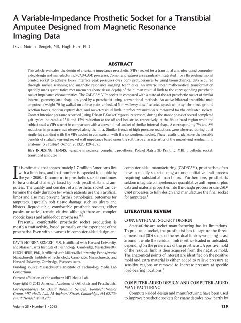
<strong>for</strong> the entire residual limb. Here, bone tissue depth<br />
Figure 2. Left, four MRI views of the right residual limb of the amputee participant. Upper left, anterior view; upper right, lateral view; lower left,<br />
medial view; lower right, 3D rendering showing bones within the limb. Right, bone tissue depth representation is shown, where red denotes the<br />
maximum bone tissue depth and green denotes the minimum depth. The bone tissue depth range is as follows: green, 0Y9 mm; and red, 20Y50 mm.<br />
MRI, magnetic resonance imaging; 3D, three-dimensional.<br />
Volume 25 & Number 3 & 2013 131
Sengeh et al.<br />
Journal of <strong>Prosthetic</strong>s and Orthotics<br />
Figure 3. Top row, three-dimensional (3D) computer-aided design of the variable impedance prosthetic socket, and the corresponding 3D printed<br />
socket is shown in the bottom row. Orientation <strong>for</strong> all images in both rows from left to right is anterior, lateral, medial, and posterior.<br />
is defined as the orthogonal distance between the surface of the<br />
skin and the intersection of bone tissue when the body is not<br />
being compressed and is in a state of equilibrium.<br />
In Figure 2, the left images represent four MRI views of the<br />
residual limb being analyzed, whereas the right image is a representation<br />
of the tissue depth measurement using the Mimics<br />
Innovation Suite. The green regions represent where the bones<br />
are closest to the skin, whereas red regions represent the regions<br />
that are furthest away from the surface of the skin.<br />
Inverse linear map between bone tissue depth and<br />
socket material stiffness<br />
An inverse linear equation is used to map bone tissue depth<br />
to socket material stiffness properties. Regions where the body<br />
was stiffest interfaced with the most compliant material, whereas<br />
regions where the body was softest interfaced with the least<br />
compliant material. Using the Mimics software, a text file was<br />
generated with estimates of bone tissue depth at each location<br />
on the residual limb. The minimum depth was identified from<br />
the bone tissue depth dataset and was mapped to the minimum<br />
modulus of elasticity used <strong>for</strong> the 3D printing material, or<br />
1.1 GPa. The maximum tissue depth, defined by the threshold<br />
value used to create the color map in Mimics, was 50 mm and<br />
was mapped to the maximum modulus of the 3D printed material,<br />
or 3 GPa.<br />
The equation generated from the above values is as follows:<br />
Y ¼ 0:0382 X þ 1:0882<br />
ð1Þ<br />
(1)where Y is the Young’s Modulus of the printing material<br />
and X is the bone tissue depth. Equation 1 represents an inverse<br />
relationship between socket material modulus and the<br />
132 Volume 25 & Number 3 & 2013
Journal of <strong>Prosthetic</strong>s and Orthotics<br />
Design of a <strong>Variable</strong>-impedance <strong>Prosthetic</strong> <strong>Socket</strong><br />
Table 1. Material properties used <strong>for</strong> FEA <strong>for</strong> the carbon fiber conventional socket and the two primary 3D printed materials used in the VIPr<br />
socket<br />
Property VeroWhitePlus Carbon fiber TangoBlackPlus<br />
Elastic modulus in X 2 10 9 N/m 2 2 10 11 N/m 2 1.4 10 9 N/m 2<br />
Poisson’s ration in XY 0.394 0.25 0.394<br />
Tensile strength in X 3 10 7 N/m 2 4 10 9 N/m 2 1 10 6 N/m 2<br />
Yield strength 5 10 7 N/m 2 3 10 8 N/m 2 1 10 6 N/m 2<br />
FEA, finite element analysis; VIPr, variable impedance prosthetic; 3D, three-dimensional.<br />
impedance of the residual limb’s soft tissue, approximated by<br />
bone tissue depth.<br />
THREE-DIMENSIONAL PRINTING OF THE<br />
VARIABLE IMPEDANCE SOCKET<br />
From the different CAD environments, the completed socket<br />
design was exported or saved as STL file <strong>for</strong>mats with the following<br />
properties: a deviation of 0.0005 in and a 5- angle to<br />
maximize the quality and detail of the design exported <strong>for</strong> printing.<br />
Because there were multiple materials with different properties<br />
in the design, each file corresponding to a different material type<br />
was saved as a unique file.<br />
Objet Geometries Inc (Billerica, MA, USA) produces an<br />
advanced 3D printer that uses their PolyJet Matrix Technology.<br />
This technology enables two different material types to be<br />
simultaneously jetted in the production of the same model<br />
using the Connexi printer with a build tray size of 500 mm <br />
400 mm 200 mm. With a 16-Km, high-resolution print layer,<br />
high dots-per-inch in both X and Y resolution, and an easy-toremove<br />
support material property, this technology was ideal <strong>for</strong><br />
the development of multimaterial prosthetic socket prototypes.<br />
In Figure 3, the designed CAD socket and the final 3D printed<br />
socket are shown. Truss structures were included as additional<br />
design features to enhance structural integrity to the socket by<br />
transmitting the high load from the stiff patella tendon region to<br />
the equally stiff distal posterior wall. The addition of the ‘‘truss’’<br />
on the VIPr socket at the indicated locations did not affect the<br />
MRI-determined material stiffness at those locations. The material<br />
property of the truss was the same as the MRI-determined<br />
materials at the location where it connected to the socket, and<br />
that impedance was maximized or highly rigid. Thus, the socket<br />
impedance <strong>for</strong> a displacement perpendicular to the inner socket<br />
surface at each inner point was largely unaffected by the addition<br />
of the trusses.<br />
The Objeti Digital Materials that provided the most variability<br />
in material properties required by our design were a combination<br />
of VeroWhitePlusi and TangoBlackPlusi. VeroWhitePlus<br />
has a modulus of elasticity ranging from 2 to 3 GPa and tensile<br />
strength ranging from 50 to 65 MPa. TangoBlackPlus has a tensile<br />
strength ranging from 0.8 to 1.5 MPa.<br />
The 3D printed VIPr socket was postprocessed by a prosthetist<br />
while keeping the internal socket shape unchanged between VIPr<br />
and conventional sockets. A distal support block <strong>for</strong> the pyramid<br />
was designed such that any standard prosthetic pyramid could be<br />
attached to the bottom of the socket. A metal base was glued<br />
to the bottom of the socket with some Coyote Design Quick<br />
Adhesive CD4150. Multiple rolls of Tech<strong>for</strong>m Premium Casting<br />
Tapei (Coyote Design & MFG, Boise, ID) of appropriate length<br />
were used in the anteroposterior and the mediolateral directions<br />
to enclose the metal base.<br />
FINITE ELEMENT ANALYSIS OF THE<br />
COMPUTER-AIDED DESIGN SOCKET<br />
Even though this project combined multiple materials into<br />
one socket through 3D printing based on biomechanical in<strong>for</strong>mation,<br />
the final VIPr socket had to be structurally sound to<br />
accommodate the dynamic walking activities of an amputee.<br />
It was assumed that all materials other than the stiffest material<br />
in the socket had negligible additional effects on the structural<br />
integrity of the socket and were thus removed from the part to be<br />
analyzed. The SolidWorks SimulationXpressi package on the<br />
SolidWorksi 3D CAD (Dassault Systèmes SolidWorks Corp,<br />
Waltham, MA) software was sufficient <strong>for</strong> the evaluation of the<br />
socket once it was reduced to a single material. Using a single<br />
material simplified the analysis and represented the worst-case<br />
scenario <strong>for</strong> structural integrity. Clearly, the overall factor of<br />
safety (FOS) would increase only if the softer materials within the<br />
socket wall were included in the analysis.<br />
To estimate the FOS <strong>for</strong> the VIPr and conventional sockets,<br />
we conducted a finite element analysis (FEA) <strong>for</strong> the case of<br />
running, the most dynamic activity the amputee participant<br />
could undergo while using the socket interfaces. The properties<br />
of the socket materials used <strong>for</strong> this FEA are presented<br />
in Table 1. For this analysis, the pressure exerted on the inner<br />
socket wall by the residual limb was assumed to be uni<strong>for</strong>mly<br />
distributed. Uni<strong>for</strong>m pressure was computed as P = (<strong>for</strong>ce/<br />
area). To calculate the area (A), a simplified circle was extracted<br />
from the sketch that <strong>for</strong>ms a planar circumference around the<br />
fibula head and the proximal end of the tibia. The estimated<br />
diameter (D) was 0.0952 m. Thus, area (A) at that plane was<br />
estimated to be (D/2) 2 = 7.1 10 j3 m 2 .<br />
The mass of the study participant was 70 kg, and thus, his<br />
weight was 686 N (W =70 9.8). To test <strong>for</strong> structural integrity,<br />
we used a <strong>for</strong>ce equal to 3 W (2058 N) as the maximum<br />
dynamically applied axial load applied to the socket during<br />
running. Thus, uni<strong>for</strong>m pressure within the socket was estimated<br />
to be P = 2058/(7.1 10 j3 ) , 290 kPa.<br />
Volume 25 & Number 3 & 2013 133
Sengeh et al.<br />
Journal of <strong>Prosthetic</strong>s and Orthotics<br />
be structural. For example, when the TangoBlackPlus material<br />
was used in the same conditions described previously, the FOS<br />
was estimated to be 0.040 <strong>for</strong> running at toe-off.<br />
Figure 4. von Mises stress representations of a completely bound<br />
socket when walking toe-off <strong>for</strong>ces are applied using material properties<br />
of VeroWhitePlus.<br />
Near toe-off in running, a point <strong>for</strong>ce was assumed to act<br />
upon the patella tendon region to account <strong>for</strong> the additional<br />
torque experienced on the socket structure. This added <strong>for</strong>ce<br />
was approximated as F =3Wcos(5), where 5 is equal to the<br />
pitch angle of the residual limb’s longitudinal axis from the<br />
horizontal. This estimated patellar <strong>for</strong>ce, F, is perpendicular to<br />
the longitudinal axis and was assumed equal to F = 1.93 kN<br />
when 5 =20-, assuming a vertical <strong>for</strong>ce equal to 3 W. For this<br />
estimate, the pitch angle of the lower leg at toe-off in running<br />
was taken from the literature. 22 Using the VeroWhitePlus<br />
material in the FEA, the FOS while running in the socket was<br />
estimated to be 2.01 (Figure 4).<br />
As a comparison with this VeroWhitePlus material, using the<br />
same <strong>for</strong>ces and conditions described earlier <strong>for</strong> a conventional<br />
carbon fiber socket material on the same CAD socket, the FOS<br />
increased to 11.96 during running at toe-off, a more than fivefold<br />
increase compared with the highest durometer 3D printed<br />
material used in this study. This result underscores the structural<br />
limitations of the 3D printed material used in this study<br />
compared with conventional prosthetic socket materials such as<br />
carbon composite. If the softer, lower-durometer 3D printed<br />
materials were assumed in the FOS estimate, the VIPr would not<br />
CLINICAL EVALUATION<br />
The Committee on the Use of Humans as Experimental<br />
Subjects at Massachusetts Institute of Technology (MIT) approved<br />
the protocol used in this project. In the study, the VIPr<br />
socket was compared with a state-of-the-art carbon prosthetic<br />
socket of similar internal geometry and shape designed by a<br />
prosthetist using conventional methods. The properties of the<br />
two sockets evaluated in this study are summarized in Table 2.<br />
An active bilateral transtibial male amputee of weight 70 kg<br />
walked on a <strong>for</strong>ce plateYembedded 5-m walkway at self-selected<br />
speeds while synchronized <strong>for</strong>ce, motion capture data, and<br />
socket-residual limb interface pressures were measured <strong>for</strong><br />
the evaluated sockets. <strong>Socket</strong> alignment was per<strong>for</strong>med by a<br />
trained prosthetist and was similar <strong>for</strong> each prosthetic intervention<br />
evaluated. The subject walked using the VIPr socket <strong>for</strong><br />
30 minutes be<strong>for</strong>e data collection. Each socket was held firmly<br />
onto the residual limb during walking activities using a standard<br />
suspension sleeve. The same prosthetic components were<br />
used <strong>for</strong> each socket, including ankle-foot and foot cover<br />
components (Össur VSP\ [Össur Americas, Foothill Ranch, CA]<br />
and cover) and prosthetic socket attachment hardware.<br />
INTERFACE PRESSURE MEASUREMENT<br />
The interface pressures between the socket and the residual<br />
limb were evaluated with special attention to specific anatomical<br />
features including the tibia and fibula head regions.<br />
Pressure was measured using the F-<strong>Socket</strong>i Pressure System<br />
provided by Tekscan, Inc (South Boston, MA, USA) at 100 Hz<br />
while the participant underwent single-leg standing. In addition,<br />
socket pressures were recorded as the participant walked<br />
10 times at self-selected speed across a <strong>for</strong>ce plateYloaded<br />
walkway while motion capture data were recorded.<br />
The pressure sensors were attached to the outside surface<br />
of the residual limb liner using double-sided tape to prevent<br />
displacement during tests (Figure 5). The flexibility, thickness,<br />
and other properties of the sensor are specifically optimized<br />
<strong>for</strong> measuring pressure in prosthetic sockets. The sensors were<br />
calibrated using Tekscan’s default walk calibration, which uses<br />
body weight and a standard level-ground walking trial to<br />
Table 2. Properties of evaluated sockets<br />
Property Conventional socket <strong>Variable</strong>-impedance three-dimensional printed socket<br />
Mass, kg 0.4811 ,1.4<br />
Internal geometry Same Same<br />
External geometry Different Different<br />
Material Carbon fiber Objet Digital Materials<br />
Compliance None Yes<br />
134 Volume 25 & Number 3 & 2013
Journal of <strong>Prosthetic</strong>s and Orthotics<br />
Design of a <strong>Variable</strong>-impedance <strong>Prosthetic</strong> <strong>Socket</strong><br />
Figure 5. Pressure sensors are taped on to the liner to cover the entire residual limb (left). The limb is then inserted into the socket (center), and a<br />
sleeve is rolled over the limb <strong>for</strong> suspension (right).<br />
calibrate all sensors. To remain consistent across trials, we<br />
applied the same walking calibration file to each recording.<br />
We used the VICON 512 motion analysis system (Ox<strong>for</strong>d<br />
Metrics, Ox<strong>for</strong>d, United Kingdom) to track kinematics as the<br />
amputee walked at a self-selected speed across a walkway embedded<br />
with two <strong>for</strong>ce plates (Advanced Mechanical Technology<br />
Inc, Watertown, MA, USA). We placed 27 reflective markers<br />
mostly on the lower limb of the participant using the Helen<br />
Hayes maker set. The pressure readings from the sensors were<br />
synchronized to the motion capture recordings using a triggering<br />
signal (high to low voltage change) from the VICON<br />
system at the start and end of each trial. Force plate measurements<br />
were fed directly into the VICON system and automatically<br />
synchronized with marker trajectories. We determined<br />
heelstrike and toe-off using ground reaction <strong>for</strong>ces, which<br />
allowed us to extract stance phase and the corresponding interface<br />
contact pressure values.<br />
The sensors stayed in the same place during data collection<br />
<strong>for</strong> both the conventional socket and the VIPr socket. We made<br />
certain that the sensors were in the same location by pressing<br />
on specific cells on the residual limb during various stages of<br />
the experimentation. We ensured that the cells on the sensor<br />
over the fibula head, <strong>for</strong> example, were the same throughout<br />
the experiments. Where the sensors overlapped, we took<br />
readings from the sensor closest to the body. Be<strong>for</strong>e and after<br />
each trial, pressure readings were recorded <strong>for</strong> some locations,<br />
and these were later crosschecked to show that there was little<br />
to no location change during the experiments.<br />
RESULTS<br />
Not surprisingly, the highest pressures recorded were during<br />
the stance phase of walking. During stance, two peaks were<br />
observed, as shown in Figures 6 and 7. The first peak occurred<br />
just after heelstrike at about 30% stance phase, whereas the<br />
second, higher peak occurred right be<strong>for</strong>e toe-off of the same leg<br />
at about 75% stance phase. During walking trials, the peak<br />
contact pressures recorded at the residual limbYsocket interface<br />
were generally lower when the amputee participant used the VIPr<br />
socket compared with the conventional socket.<br />
Specifically, while the participant walked at a preferred<br />
speed using the VIPr socket, we observed a 17% and 15% reduction<br />
in peak contact pressure on the fibula head region <strong>for</strong><br />
the first and second peaks, respectively, in comparison with the<br />
conventional socket (Figure 6). A corresponding 8% and 7%<br />
reduction in contact pressure was observed along the tibia<br />
region (Figure 7). For these experiments, the preferred walking<br />
speeds of the participant were 0.84 and 0.72 m/s while using<br />
the VIPr and conventional socket, respectively. At the fibula<br />
head and tibia regions during single-leg standing, use of the<br />
VIPr socket also produced lower interface contact pressures of<br />
13% and 21%, respectively (Figures 8 and 9).<br />
CONCLUSION AND FUTURE WORK<br />
Using conventional socket technology, nearly all amputees<br />
experience residual limb discom<strong>for</strong>t due in part to excessive<br />
pressures over anatomical points. In this investigation with a<br />
single study participant, we showed that the contact pressures<br />
over the fibula and tibia anatomical landmarks were decreased in<br />
a VIPr socket during preferred speed walking and singleleg<br />
standing in comparison with a uni<strong>for</strong>mly rigid conventional<br />
socket. Furthermore, we observed a 16% increase in the<br />
self-selected walking speed of the participant while using a<br />
VIPr socket.<br />
In this study, the VIPr socket was nearly three times heavier<br />
than the conventional carbon socket. The present weight of the<br />
VIPr socket is caused by the poor mechanical properties of its<br />
3D printed materials and the resulting large socket-wall thicknesses<br />
necessary to achieve structural integrity. The FOS of the<br />
Volume 25 & Number 3 & 2013 135
Sengeh et al.<br />
Journal of <strong>Prosthetic</strong>s and Orthotics<br />
Figure 6. Contact pressures <strong>for</strong> the variable impedance prosthetic<br />
socket and the conventional socket <strong>for</strong> the same fibula head region<br />
(shown as the darkened box on the image of the residual limb) are plotted<br />
versus percentage stance period. Shown are mean pressure data T 1SD<br />
<strong>for</strong> n = 10 walking gait cycles measured at a preferred gait speed.<br />
Figure 8. Mean contact pressures T 1 SD <strong>for</strong> the two socket interventions<br />
measured over the same fibula head region during singleleg<br />
standing <strong>for</strong> 4 seconds at 100 Hz.<br />
lighter conventional carbon socket far exceeded that of the<br />
heavier 3D printed VIPr socket. If the library of 3D printed<br />
materials grows to contain materials of higher Young’s Modulus<br />
and higher tensile strengths, the weight of a 3D printed VIPr<br />
design and the thickness of its walls could be further reduced. In<br />
a future investigation, one would hope that structural integrity<br />
could be achieved through digital fabrication as the diversity<br />
of materials increases in the marketplace. However, be<strong>for</strong>e such<br />
improvements in digital fabrication are broadly available in<br />
the marketplace, there exists a need to explore the manufacture<br />
of com<strong>for</strong>table VIPr socket designs through a combination,<br />
perhaps, of CAD/CAM and more traditional fabrication techniques.<br />
In addition to improvements in fabrication technique, a<br />
broader clinical study will be necessary to more deeply understand<br />
the relationship between excessive socket pressure and<br />
socket variable impedance properties. In the design of transtibial<br />
prosthetic sockets, we feel that smoothly varying socket wall<br />
impedance in a manner that is inversely proportional to the<br />
impedance of the underlying anatomy is of critical importance.<br />
ACKNOWLEDGMENTS<br />
The authors thank Gerald Berberian and Objet Geometries Inc <strong>for</strong><br />
allowing the use of the Objet Connex 3D printer. The authors also<br />
thank Steve Shannon and Christina Triantafyllou at the McGovern<br />
Institute <strong>for</strong> Brain Research at MIT <strong>for</strong> assisting with the MRI data<br />
collection. Finally, the authors thank David Hill <strong>for</strong> helping with data<br />
processing and prosthetist Bob Emerson <strong>for</strong> his work in helping them<br />
capture the shape of the amputee participant’s conventional socket.<br />
Figure 7. Contact pressures <strong>for</strong> the variable impedance prosthetic socket<br />
and the conventional socket <strong>for</strong> the same tibia region (shown as the<br />
darkened box on the image of the residual limb) are plotted versus percentage<br />
stance period. As in Figure 6, shown are mean pressure data T 1<br />
SD <strong>for</strong> n = 10 walking gait cycles measured at a preferred gait speed.<br />
Figure 9. Mean contact pressures T 1 SD <strong>for</strong> the two socket interventions<br />
measured over the same tibia region during single-leg<br />
standing <strong>for</strong> 4 seconds at 100 Hz.<br />
136 Volume 25 & Number 3 & 2013
Journal of <strong>Prosthetic</strong>s and Orthotics<br />
REFERENCES<br />
1. Ziegler-Graham K, MacKenzie EJ, Ephraim PL, et al. Estimating<br />
the prevalence of limb loss in the United States: 2005 to 2050.<br />
Arch Phys Med Rehabil 2008;89:422Y429.<br />
2. Martinez-Villalpando EC, Herr H. Agonist-antagonist active knee<br />
prosthesis: a preliminary study in level-ground walking. J Rehabil<br />
Res Dev 2009;46:361Y373.<br />
3. Au SK, Webber J, Herr H. Powered ankle-foot prosthesis improves<br />
walking metabolic economy. IEEE Trans Robot 2009;25:51Y66.<br />
4. Smith DG, Burgess EM. The use of CAD/CAM technology in<br />
prosthetics and orthoticsVcurrent clinical models and a view<br />
to the future. J Rehabil Res Dev 2001;38:327Y334.<br />
5. Muller M, Staats TB, Leach M, Fothergill I. Total surface bearing transtibial<br />
socket design impression techniques. JProc2007; available<br />
at http://www.oandp.org/publications/jop/2007/2007-49.asp.<br />
6. Faustini MC, Craw<strong>for</strong>d RH, Neptune RR, et al. Design and analysis<br />
of orthogonally compliant features <strong>for</strong> local contact pressure relief<br />
in transtibial prostheses. J Biomech Eng 2005;127:946Y951.<br />
7. Facoetti G, Gabbiadini S, Colombo G, Rizzi C. Knowledge-based<br />
system <strong>for</strong> guided modeling of sockets <strong>for</strong> lower limb prostheses.<br />
Comput Aided Des Appl 2010;7:723Y737.<br />
8. Moo EK, Osman NAA, Pingguan-Murphy B, et al. Interface pressure<br />
profile analysis <strong>for</strong> patellar tendon-bearing socket and hydrostatic<br />
socket. Acta Bioeng Biomech 2009;11:37Y44.<br />
9. Topper AK, Fernie GR. Computer-aided design and computeraided<br />
manufacturing (CAD/CAM) in prosthetics. Clin Orthop<br />
Relat Res 1989;256:39Y43.<br />
10. Rogers B, Bosker GW, Craw<strong>for</strong>d RH, et al. Advanced trans-tibial<br />
socket fabrication using selective laser sintering. Prosthet Orthot<br />
Int 2007;31:88Y100.<br />
11. Torres-Moreno R, Morrison JB, Cooper D, et al. A computer-aided<br />
socket design procedure <strong>for</strong> above-knee prostheses. Bull Prosthet<br />
Res 1992;29:35Y44.<br />
.<br />
Design of a <strong>Variable</strong>-impedance <strong>Prosthetic</strong> <strong>Socket</strong><br />
12. Tay FEH, Manna MA, Liu LX. A CASD/CASM method <strong>for</strong> prosthetic<br />
socket fabrication using the FDM technology. Rapid Prototyping<br />
J 2002;8:258Y262.<br />
13. Torres-Moreno R, Saunders CG, Foort J, Morrison JB. Computeraided<br />
and manufacture of above-knee socket. J Biomed Eng<br />
1991;13:3Y9.<br />
14. Ng P, Lee PVS, Goh JCH. <strong>Prosthetic</strong> sockets fabrication using<br />
rapid prototyping technology. Rapid Prototyping 2002;8:53Y59.<br />
15. Rogers B, Stephens S, Gitter A, et al. Double-wall, transtibial<br />
prosthetic socket fabricated using selective laser sintering: a<br />
case study. J Prosthet Orthot 2000;12:97Y100.<br />
16. Douglas T, Solomonidis S, Sandham W, Spence W. Ultrasound<br />
imaging in lower limb prosthetics. IEEE Trans Neural Rehabil<br />
Syst Eng 2002;10:11Y21.<br />
17. He P, Xue KF, Fan Y, Wang YW. Test of a vertical scan mode in 3D<br />
imaging of residual limbs using ultrasound. J Rehabil Res Dev<br />
1999;36:86Y93.<br />
18. Zheng Y, Mak AFT, Lue B. Objective assessment of limb tissue<br />
elasticity: development of a manual indentation procedure.<br />
J Rehabil Res Dev 1999;36:71Y85.<br />
19. Buis A, Condon B, Brennan D, et al. Magnetic resonance imaging<br />
technology in transtibial socket research: a pilot study. Gait<br />
Posture 2006;43:883Y890.<br />
20. Zhang M, Mak, FT, Chung AIK, Chung KH. MRI investigation<br />
of musculoskeletal action of transfemoral residual limb inside<br />
a prosthetic socket. 1998 Proceedings of the 20th Annual<br />
International Conference of the IEEE Engineering in Medicine<br />
and Biology Society. 20:2741Y2743.<br />
21. Udai AD, Sinha AN. Processing magnetic resonance images <strong>for</strong> CAD<br />
model development of prosthetic limbs socket. 2008IEEE Region<br />
10 and the Third International Conference on Industrial and<br />
In<strong>for</strong>mation Systems. 70:1Y5.<br />
22. Novacheck TF. The biomechanics of running. Gait Posture 1998;<br />
7:77Y95.<br />
Volume 25 & Number 3 & 2013 137


