- Page 1 and 2: Copyright Warning & Restrictions Th
- Page 3 and 4: ABSTRACT SHEAR STRENGTHENING OF RC
- Page 5 and 6: SHEAR STRENGTHENING OF RC BEAMS USI
- Page 7 and 8: APPROVAL PAGE SHEAR STRENGTHENING O
- Page 9 and 10: This dissertation is dedicated to m
- Page 11 and 12: TABLE OF CONTENTS Chapter Page 1 IN
- Page 13 and 14: TABLE OF CONTENTS (Continued) Chapt
- Page 15 and 16: LIST OF TABLES Chapter Page 2.1 Max
- Page 17 and 18: LIST OF FIGURES (Continued) Chapter
- Page 19 and 20: LIST OF FIGURES (Continued) Chapter
- Page 21 and 22: LIST OF FIGURES (Continued) Chapter
- Page 23 and 24: 2 Additionally, special equipment i
- Page 25 and 26: 4 5. To study the shear span to dep
- Page 27 and 28: 6 1.4.1 Shear Strength of RC Beams
- Page 29 and 30: Where A, is the area of shear reinf
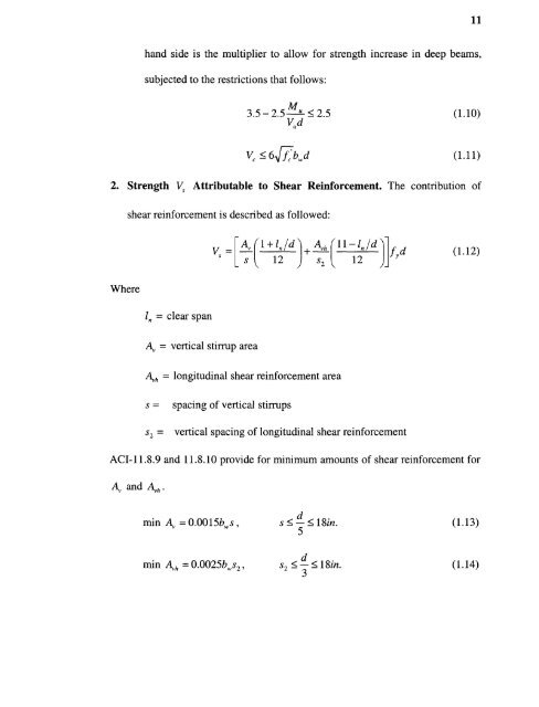
- Page 31: 10 usually be the same throughout t
- Page 35 and 36: 14 based on the assumption that the
- Page 37 and 38: CHAPTER 2 EXPERIMENTAL PROGRAM ON S
- Page 39 and 40: 18 needed, which was 4Omm wide and
- Page 41: 20 used for bonding of the strips t
- Page 45 and 46: 24 2.2 Instrumentation and Test Pro
- Page 47 and 48: 26 b) Beam Z4-90 The next beam was
- Page 49 and 50: 28 CFRP strip suddenly detached fro
- Page 51 and 52: 30 Figure 2.17 Failure of Beam ZC6.
- Page 53 and 54: 32 capacity. The load went straight
- Page 55 and 56: 34 Figure 2.22 Failure of Beam Z6-9
- Page 58 and 59: 37 c) Failure Mechanism Apparently,
- Page 60 and 61: 39 observed by a prolonged portion
- Page 63 and 64: 42 c) Failure Mechanism Since diffe
- Page 65 and 66: 44 The equation to compute CARP she
- Page 67 and 68: 46 3.2 Design Approach Based on Mod
- Page 70: 49 Arom Aigure 3.2, it can be obser
- Page 74 and 75: 53 Equation 3.12 from curve fitting
- Page 76 and 77: 55 strength. The method based on bo
- Page 78 and 79: 57 Chajes, M. J. et al. (1996) also
- Page 80 and 81: 3) CFRP continuous fiber sheet in t
- Page 82 and 83:
Figure 3.11 CARP strip in the form
- Page 84 and 85:
63 Thus, a relationship between the
- Page 86 and 87:
65 2 fc bi,d I f =wife • t f ' fi
- Page 88 and 89:
67 Arom Table 3.4, it can also be o
- Page 90 and 91:
69 equal to 3.75, the beam specimen
- Page 92 and 93:
71 laminates. The surfaces of the f
- Page 94 and 95:
Figure 4.3 Configuration of CARP st
- Page 96:
75 16 beams were tested in this res
- Page 100 and 101:
79 Figure 4.7 Typical test setup. 4
- Page 102 and 103:
81 intact. The CFRP strip delaminat
- Page 104 and 105:
83 4.5.1.4 Beam Z11-S45. The CFRP s
- Page 106 and 107:
85 4.5.2 Beam Group 2 4.5.2.1 Beam
- Page 108 and 109:
87 4.5.2.3 Beam Z22-S90. This beam
- Page 110 and 111:
89 (b) Right Side Figure 4.15 Failu
- Page 112 and 113:
91 of the delamination, which consi
- Page 114 and 115:
93 Figure 4.18 Failure of Beam Z31-
- Page 116 and 117:
95 4.5.4 Beam Group 4 4.5.4.1 Beam
- Page 118 and 119:
97 4.5.4.3 Beam Z42-FD. This was th
- Page 120 and 121:
99 (a) Side View of the Beam at Fai
- Page 122 and 123:
101 4.6 Test Results and Discussion
- Page 124 and 125:
103 failure along the inclined crac
- Page 126 and 127:
105
- Page 128 and 129:
107 4.6.3 Beam Group 3 A summary of
- Page 130 and 131:
109 4.6.3.3 Failure Mechanism. No i
- Page 132 and 133:
111 ;how deflections at ultimate lo
- Page 134 and 135:
113 All of the lines in Figure 4.28
- Page 136 and 137:
115 ratio; line Z-F90 means the var
- Page 138 and 139:
117 Unlike regular beams with large
- Page 140 and 141:
119 orientation of the CFRP strips
- Page 142 and 143:
121 As for shear design of deep bea
- Page 144 and 145:
123 provisions of ACI Code (ACI 318
- Page 146 and 147:
125 stress due to shear as well as
- Page 148 and 149:
Figure 5.3 Distribution of transver
- Page 150 and 151:
Figure 5.4 Estimation of effective
- Page 152 and 153:
131 Where A and Ah are the areas of
- Page 154 and 155:
Since the principal tensile stress
- Page 156 and 157:
135 laminates can be obtained from
- Page 158 and 159:
Table 5.1 Experimental and Computed
- Page 160 and 161:
139 Where i denote each type of rei
- Page 162 and 163:
141 the strongest beam in the 4-foo
- Page 164 and 165:
143 Figure 6.1 Failure of Beam ZC4-
- Page 166 and 167:
145 Figure 6.3 Failure of Beam Z22-
- Page 168 and 169:
147 6.2.4 Analysis of Test Results
- Page 170 and 171:
149 improves the performance of the
- Page 172 and 173:
Figure 6.7 Test result of beam Z22-
- Page 174 and 175:
Figure 6.8 Test result of Beam Z3I-
- Page 176 and 177:
155 equal to 69 degrees in this cas
- Page 178 and 179:
157 decreases, while the shear cont
- Page 180 and 181:
APPENDIX A LOAD DEFLECTION CURVES O
- Page 182 and 183:
161 Figure A.3 Load deflection curv
- Page 184 and 185:
163 Figure A.7 Load deflection curv
- Page 186 and 187:
Figure A.11 Load deflection curve o
- Page 188 and 189:
167 Figure B.1 Load deflection curv
- Page 190 and 191:
169 Figure B.5 Load deflection curv
- Page 192 and 193:
171 Figure B.9 Load deflection curv
- Page 194 and 195:
173 Figure B.13 Load deflection cur
- Page 196 and 197:
APPENDIX C LOAD DEFLECTION CURVES O
- Page 198 and 199:
177 Figure C.3 Load deflection curv
- Page 200 and 201:
179 Czaderski, Christoph. "Shear St
- Page 202:
181 4, No. 4, Nov. 2000, pp. 198-20