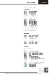
Designer 1000 Assembly Details - Ullrich Aluminium
Designer 1000 Assembly Details - Ullrich Aluminium
Designer 1000 Assembly Details - Ullrich Aluminium

Create successful ePaper yourself
Turn your PDF publications into a flip-book with our unique Google optimized e-Paper software.
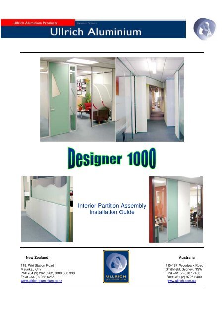
Interior Partition <strong>Assembly</strong><br />
Installation Guide<br />
New Zealand<br />
Australia<br />
118, Wiri Station Road 185-187, Woodpark Road<br />
Maunkau City<br />
Smithfield, Sydney, NSW<br />
Ph# +64 (9) 262 6262, 0800 500 338 Ph# +61 (2) 8787 7400<br />
Fax# +64 (9) 262 6265 Fax# +61 (2) 9725 2400<br />
www.ullrich-aluminium.co.nz<br />
www.ullrich.com.au
Introduction<br />
The intension of this booklet is to not hard sell to you on the benefits of ‘<strong>Designer</strong> <strong>1000</strong>’<br />
partitioning as opposed to other low recovery partitioning systems, but to simply acquaint you (as the<br />
client) with the full range and versatility of the suite, and to better enlighten yourself as to the merits of<br />
one concept as opposed to another.<br />
You will achieve a better understanding of your chosen concept, as to exactly what has gone<br />
into your office system and conclude that you are indeed achieving value for your investment.<br />
No effort has been spared developing to the fullest all partition suites, as with this booklet to<br />
present you with the latest, innovative and most up to date economical solution to any perceived<br />
requirement in an unbiased fashion. With this in mind you will note that all concepts have been<br />
rigorously tested by ‘BRANZ’ and endorsed as achieving, and indeed exceeding all specifications<br />
deemed as necessary for individual concepts.<br />
In conclusion we would add that, should your desired concept not be prepared in this booklet<br />
then we can only say that at the time of print it had not been thought of, and that we would gladly<br />
welcome your enquiry.<br />
<strong>Designer</strong> <strong>1000</strong> Installation Manual Page 1 of 14
<strong>Designer</strong> <strong>1000</strong> Partitioning Into 2000 and Beyond<br />
1. Introduction<br />
2. Index<br />
3. Sound Transmission Code (STC)<br />
4. Solid Wall Non – Load Bearing / 10 mm Gibraltar Board<br />
5. Solid Wall Non – Load Bearing / 13 mm Gibraltar Board<br />
6. Solid Wall Non – Load Bearing / 13 mm Double Laminate<br />
7. Door Framing / Partial Height / Solid Wall<br />
8. Door Framing / Full Height / Solid Wall<br />
9. Door Framing / Partial Height / Glazed Wall<br />
10. Door Framing / Full Height / Glazed Wall<br />
11. Full Height Glazed Wall<br />
12. Single Glazed Walls with Ducting<br />
13. Double Glazed Walls<br />
<strong>Designer</strong> <strong>1000</strong> Installation Manual Page 2 of 14
Sound Transmission Code (STC)<br />
Sound insulation is measured in decibels (dB). If a sound level of 70 dB is generated in one<br />
room, and the sound level in the adjacent room is 30 dB, the difference between the sound levels is a<br />
measure of insulation provided by the wall and the wall is referred to as having 70 dB – 30 dB = 40 dB<br />
sound transmission loss. A factor that must be considered in the background noise level, also<br />
measured in dB. This will mask an equivalent amount of sound (in dB) already present in the room.<br />
Background noises can be caused by street traffic, trains, mechanical equipment etc, and the level of<br />
this background noise is dependent upon the building and room location.<br />
The basic objective, therefore in sound insulation is to reduce the transmitted noise level (i.e. the<br />
aforementioned 30 dB level in the second room) below that of the background noise or to an<br />
acceptable level, whichever is greater.<br />
To compare the effectiveness of a wall or the floor construction in preventing the passage of<br />
airborne sound, a two room sound test method is generally used. A steady, known sound level of a<br />
certain frequency is generated on one side of the wall (or floor) and then measured in the room on the<br />
other side. This enables a wall sound transmission loss (dB) to be calculated and this recorded. Sound<br />
levels of other frequencies are also included in the test procedure, resulting in a variety of wall sound<br />
transmission losses.<br />
Obtained from this data is the STC or the Sound Transmission Class of the wall or floor. The<br />
STC is a convenient single number acoustic rating for walls and other partitions. The STC rating is<br />
easy to use and is currently the most realistic way to compare acoustic performance. The higher the<br />
STC value, the better the assembly will resist sound passage.<br />
Sound Transmission Class (STC)<br />
Example of how STCs relate to partition performance<br />
25 30 35 42 45 48 50<br />
Loud speech<br />
Only some<br />
Loud speech Loud speech can be heard Must strain to loud speech<br />
can be heard can be heard but only as a hear loud can be<br />
quite easily not understood murmur speech barely heard<br />
Normal speech<br />
can be heard<br />
quite easily<br />
Wall Performance – Lab and In – Situ<br />
Loud speech<br />
cannot be heard<br />
The most common method of rating the wall or floor sound transmission performance is by using<br />
the laboratory obtained STC value.<br />
While the manufacturers of building materials and systems may exercise great care to properly<br />
determine the acoustic performance of their products, many of the benefits of walls and floors with high<br />
STC ratings can be lost because of poor construction details or improper installation. The laboratory<br />
measured performance of partitions will not be achieved in buildings unless both the specification of the<br />
acoustically rated wall and the construction details described later are strictly followed. Laboratory STC<br />
ratings of partitions alone do not necessarily determine the acoustic privacy of the total construction. In<br />
fact, a tested partition of STC rating 50 may only achieve STC 40 or worse if in – situ construction is not<br />
of the highest standard.<br />
<strong>Designer</strong> <strong>1000</strong> Installation Manual Page 3 of 14
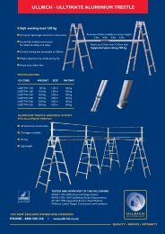
Solid Wall Non – Load Bearing, 10 mm Gibraltar Board Lining<br />
Steel Stud Sound Transimission Soft Body Test Deflection F.R.R.<br />
10 mm Gibraltar Board Partition <strong>Assembly</strong><br />
This wall is best suited as a medium quality full height room<br />
divider where sound transmission is of low priority. The wall<br />
surface is not as flat as that of 13 mm gibboard.<br />
NOTE: Head Starter UA 4359 if Powder coated / Anodized<br />
Vertical Section Showing Inner Detail<br />
<strong>Designer</strong> <strong>1000</strong> Installation Manual Page 4 of 14
Solid Wall Non – Load Bearing, 13 mm Gibraltar Board Partition<br />
Steel Stud Sound Transimission Soft Body Impact Test Deflection F.R.R. Hours<br />
63.5 x 0.55 1 / 2<br />
63.5 x 0.7 1 / 2<br />
13 mm Gibraltar Board Partition <strong>Assembly</strong><br />
This wall is best suited as a high quality full height room<br />
divider where sound transmission is of low priority. The<br />
thicker lining gives a flatter and stronger surface<br />
NOTE: Head Starter UA 4362 if Powder coated / Anodized<br />
Starter Cap UA 4364 if Anodized<br />
Starter Cap UA 4363 if Powder coated<br />
Vertical Section Showing Inner <strong>Details</strong><br />
<strong>Designer</strong> <strong>1000</strong> Installation Manual Page 5 of 14
Solid Wall Non – Load Bearing 13 mm, Double Laminated Gibraltar Board<br />
Steel Stud Sound Transimission Soft Body Impact Test Deflection F.R.R. Hours<br />
63.5 x 0.55<br />
63.5 x 0.7<br />
S.B.adhesive by SIKA between gibboard and<br />
stud.<br />
Fix with 32x6 drywall screws @300 centres<br />
(by <strong>Ullrich</strong> <strong>Aluminium</strong>)<br />
13 mm Double Laminated Gibraltar<br />
Board Partition <strong>Assembly</strong><br />
Sections Showing Inner <strong>Details</strong> of the <strong>Assembly</strong><br />
<strong>Designer</strong> <strong>1000</strong> Installation Manual Page 6 of 14
Door Framing / Partial Height / Solid Wall<br />
S.T.C. Slam Test Soft Body Impact Deflection<br />
Partial Height Door<br />
This concept is best suited where standard 1980 mm high<br />
doors are required in leu of the full height door. This option<br />
also lends itself well to the addition of a borrowed light<br />
window above the door simply be including glazing bar and<br />
bead.<br />
NOTE: Head Starter UA 4359 if Powder coated / Anodized<br />
Door Jamb UA 1788 38 – 42 mm Doors<br />
UA 2062 42 – 47 mm Doors<br />
<strong>Designer</strong> <strong>1000</strong> Installation Manual Page 7 of 14
Door Frame / Full Height / Solid Wall<br />
S.T.C. Slam Test Soft Body Impact Deflection<br />
Full Height Door Solid Wall<br />
This concept is best suited when the least amount of<br />
sound transmission is required together with architrave<br />
sound.<br />
NOTE: Head Starter UA 4359 if Powder coated / Anodized<br />
Starter Cap UA 4360 if Powder coated / Anodized<br />
Door Jamb UA 1788 38 – 42 mm Doors<br />
UA 2062 42 – 47 mm Doors<br />
<strong>Designer</strong> <strong>1000</strong> Installation Manual Page 8 of 14
Door Framing / Partial Height / Glass Wall<br />
S.T.C. Slam Test Soft Body Impact Deflection<br />
Partial Height Door Glazed Wall <strong>Assembly</strong><br />
This concept is best suited where standard 1980 mm<br />
high doors are required in leu of the full height door.<br />
Not recommended in a high traffic area when a seismic<br />
bracing is required, as top of the door jamb is not<br />
anchored.<br />
NOTE: Door Jamb UA 1788 38 – 42 mm Doors<br />
UA 2062 42 – 47 mm Doors<br />
<strong>Designer</strong> <strong>1000</strong> Installation Manual Page 9 of 14
Door Framing / Full Height / Glass Wall<br />
S.T.C. Slam Test Soft Body Impact Deflection<br />
Full Height Glazed Wall Door Frame <strong>Assembly</strong><br />
NB: Minimum 4 flush butt hinges required.<br />
Ideally suited in a high traffic area where glazed walls are<br />
desire, this lands itself well to seismic bracing above the<br />
door, as opposed to the partial height option.<br />
NOTE: Door Jamb UA 1788 38 – 42 mm Doors<br />
UA 2062 42 – 47 mm Doors<br />
Glazing Bead UA 1035 if Powdercoated<br />
UA 3209 if Anodized<br />
Glazing Bar UA 1034<br />
<strong>Designer</strong> <strong>1000</strong> Installation Manual Page 10 of 14
Full Height Glazed Partition<br />
S.T.C. Soft Body Impact Deflection<br />
Full Height Glazed Partition <strong>Assembly</strong><br />
This is an ideal wall option when an additional amount of<br />
natural light is required together with and / or visual<br />
access to other office areas. When the colonial bead<br />
option is utilized a greater degree of deflection reduction<br />
is achieved.<br />
NOTE: Head Starter UA4360 if Powder coated / Anodized<br />
Vertical Section Showing Inner <strong>Details</strong><br />
Glazing Bar UA 1034<br />
Glazing Bead UA 1035 if Powdercoated<br />
UA 3209 if Anodized<br />
<strong>Designer</strong> <strong>1000</strong> Installation Manual Page 11 of 14
Glazed Partition with Ducting<br />
Glass S.T.C. Deflection<br />
Single Glazed 3 Channel Ducts <strong>Assembly</strong><br />
Vertical Section Showing Inner <strong>Details</strong><br />
Ideal option where a small amount of telephone, data and power reticulation is required and still retain<br />
the benefits of full glazing.<br />
This option can be utilized at either floor level or at desk height, the latter also providing the added<br />
benefit of a vision / crash rail in high traffic areas.<br />
NOTE: Ducting Base UA 1040<br />
Ducting Divider UA 1041<br />
Ducting Lid UA 1042<br />
<strong>Designer</strong> <strong>1000</strong> Installation Manual Page 12 of 14
Double Glazed Partition<br />
Glass S.T.C. Deflection<br />
6 mm + 6 mm<br />
6 mm + 10 mm<br />
6 mm + 10 mm<br />
Double Glazed Wall <strong>Assembly</strong><br />
Vertical Section Showing Inner <strong>Details</strong><br />
This is the ultimate option for sound transmission reduction when high visibility light inter office is<br />
required to accommodate occasional requirements for privacy, then the addition of micro binds<br />
between the glass panels is recommended with the added benefit of maintenance free (cleaning).<br />
Remote control operation of binds is also worth considering.<br />
NOTE: Double Glazing UA 1314<br />
Double Glazing Cap UA 1313<br />
Glazing Bead UA 1035<br />
<strong>Designer</strong> <strong>1000</strong> Installation Manual Page 13 of 14