Untitled
Untitled
Untitled

You also want an ePaper? Increase the reach of your titles
YUMPU automatically turns print PDFs into web optimized ePapers that Google loves.
Falko Langenhorst<br />
a<br />
b<br />
booster<br />
laser<br />
d<br />
D<br />
high explosive<br />
flyer plate<br />
spacing ring<br />
cover layer<br />
specimen<br />
Fe cylinder<br />
vacuum<br />
chamber<br />
lens<br />
mirrors<br />
sample<br />
steel blocks<br />
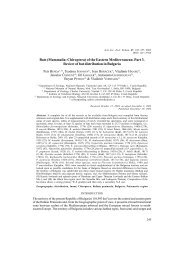
Fig. 4. Two different experimental designs to produce shock waves: (a) High-explosive device used at the Ernst-Mach-Institut, Efringen-Kirchen, Germany<br />
(modified after Langenhorst and Deutsch 1994) and (b) a laser irradiation setup with the sample being clamped into an Al block. The laser is focused<br />
on a thin Al foil, acting as flyer plate (modified after Langenhorst et al. 1999a and 2002a).<br />
minerals (e.g. French and Short 1968, Roddy et al. 1977,<br />
Asay and Shahinpoor 1993, Davison et al. 2002).<br />
Most experiments related to cratering mechanics employ<br />
spherical projectiles that produce and excavate some<br />
crater in an infinite half space medium via a spherically<br />
expanding shock wave. In contrast, most experiments related<br />
to shock metamorphism employ flat-plate projectiles<br />
that drive a planar shock wave through a similarly planar<br />
target; the thickness of the latter is typically less than projectile<br />
thickness to avoid measurable pressure decay<br />
across the sample (Barker et al. 1993). The target is usually<br />
a metallic container, encapsulating the sample in a fashion<br />
to allow its partial or complete recovery. The<br />
experiments may differ widely in the type of accelerating<br />
system (Fig. 4): powder and light-gas guns, high-explosive<br />
charges, electric discharge guns, and laser irradiation techniques<br />
have been used and tested to successfully reproduce<br />
shock effects in minerals (e.g. Milton and DeCarli<br />
1963, Müller and Hornemann 1969, Gratz et al. 1992,<br />
Stöffler and Langenhorst 1994, Langenhorst et al. 1999a,<br />
2002a). The principle of the electric gun is to vaporise a<br />
thin metal foil by rapid electric discharge of a capacitor.<br />
The high electrical current leads to the instantaneous vaporisation<br />
of the foil and the production of a shock wave<br />
(Langenhorst et al. 2002a). Laser irradiation experiments<br />
can be performed either with or without a projectile. In the<br />
latter case, the beam is directly focused on the sample surface<br />
(Langenhorst et al. 2002a), whereby the absorption of<br />
the laser energy generates rapidly exploding plasma that<br />
subsequently induces a shock wave. Such plasma techniques<br />
are capable to produce the highest shock pressures<br />
with an unbelievable world record of 750 Mbar (Cauble et<br />
al. 1993). However, higher shock pressures are commonly<br />
at the expense of shorter shock durations and smaller sample<br />
volumes. This is because higher impact velocities and<br />
hence higher shock pressures can only be achieved by reducing<br />
the size and weight of the projectile. Typical pressure<br />
pulses in laser irradiation, electric discharge and highexplosive<br />
experiments are approximately 1 ns, 10 ns, and<br />
1 µs with shocked sample volumes on the order of 0.1, 1,<br />
and 100 mm 3 , respectively (Langenhorst et al. 2002a).<br />
To determine pressures in shock experiments it is necessary<br />
to measure the velocities associated with the shock<br />
waves (projectile v, particle u and shock U velocities), using<br />
electrical pin contact, optical interferometry (VISAR)<br />
or similar techniques (Hornemann and Müller 1971, Barker<br />
et al. 1993). It is then possible to calculate the pressures<br />
temperature (°C)<br />
3000<br />
2500<br />
2000<br />
1500<br />
1000<br />
500<br />
quartz<br />
eclogite<br />
liquid<br />
coesite<br />
release<br />
paths<br />
stishovite<br />
porous sandstone<br />
0<br />
1 10<br />
100<br />
shock pressure (GPa)<br />
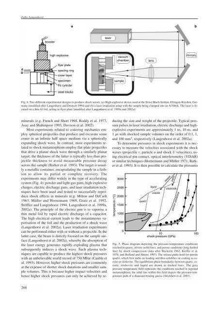
Fig. 5. Phase diagram depicting the pressure-temperature conditions<br />
reached in quartz, olivine (solid line), and porous sandstone (long dashed<br />
line) by shock compression (data after Wackerle 1962, Kieffer et al.<br />
1976, and Holland and Ahrens 1997). The release paths hold for porous<br />
quartz, which first melts on loading and then solidifies on cooling as coesite<br />
or stishovite. The equilibrium phase boundaries between quartz, coesite,<br />
stishovite and liquid are drawn as dashed lines. The grey<br />
pressure-temperature field represents the conditions reached in regional<br />
metamorphism; the solid line within this field depicts the pressure-temperature<br />
path of a diamond-bearing gneiss (Stöckhert et al. 2001).<br />
quartz<br />
olivine<br />
268