HAM-MAG - arkansas ares races
HAM-MAG - arkansas ares races
HAM-MAG - arkansas ares races

You also want an ePaper? Increase the reach of your titles
YUMPU automatically turns print PDFs into web optimized ePapers that Google loves.
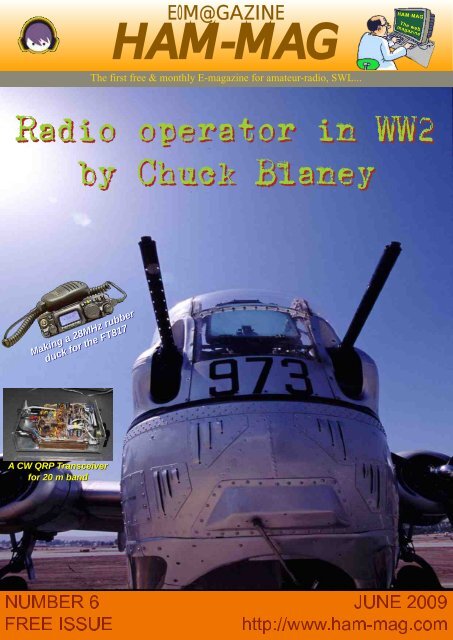
E-M@GAZINE<br />
<strong>HAM</strong>-<strong>MAG</strong><br />
The first free & monthly Emagazine for amateurradio, SWL...<br />
Radio operator in WW2<br />
by Chuck Blaney<br />
Making a 28MHz rubber<br />
duck for the FT817<br />
A CW QRP Transceiver<br />
for 20 m band
The HamMag Hall of fame............................................ 3<br />
A CW QRP Transceiver for 20m By IK3OIL........... 4<br />
Compact Bugout comm trailer By W5FTV........ 11<br />
A 28MHz rubber duck for FT817 By G0FTD...... 14<br />
The DXnews from the Web.................................. 16<br />
The DX Calendar By SM3CVM........................... 19<br />
Oscillating damped waves By ON4BX.............. 21<br />
Chuck Blaney WW2 operator radio.................. 31<br />
Comic's <strong>HAM</strong>........................................................ 36<br />
Thanks to : Chuck Blaney, IK3OIL, GØFTD, ON4BX, SM3CVM, W5FTV<br />
Thanks also to the OM's who believe in this magazine, to all the donators and<br />
OM's who sent helpful messages.<br />
You can contact us by EMail : postmaster@hammag.com<br />
Our websites :<br />
http://www.hammag.com (English)<br />
http://www.hammag.fr (French)<br />
ISSN N.17606470
The Hall of Fame<br />
Donators of MAY<br />
8 generous donators<br />
for this month...<br />
Mark Wall<br />
G3VFP, Dave<br />
Ross Bell<br />
Edwin Weal<br />
KD5WQD, Don<br />
MØWYM, Charlie<br />
WE9C, Gene<br />
EA2HI, Herman<br />
Thanks a lot for your support !<br />
To live <strong>HAM</strong><strong>MAG</strong> needs you.<br />
Any help is welcome.<br />
Send us articles, informations.<br />
We have received few articles for this issue<br />
and we have nothing for the next one !<br />
http://www.hammag.com
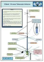
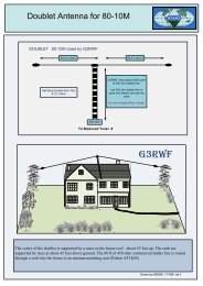
A CW QRP Transceiver for 20 m band<br />
By IK3OIL<br />
The little QRP presented in this article may be built in a gradual manner, in fact it is divided<br />
in two main modules (plus VFO), you may also complete only a single part (RX or TX module).<br />
Also the VFO module may be built with two complexity levels, as a conversion VFO or as a<br />
free oscillator, obtaining slightly different performances.<br />
In other words the project looks completely modular, the tuning requires at least a frequency<br />
meter, a signal generator and an RF probe, if you have at your disposal an oscilloscope, this<br />
could make the job simpler.<br />
How it is made<br />
The transceiver is composed by three single sided printed boards 100x70 mm, theese may be<br />
stacked so as to reduce the overall size of the metal cabinet. I suggest to employ small size<br />
components (1/4 W resistors, 2,5 mm capacitors, …) wich should fit better on the PCB boards.<br />
On the front panel you may place the tuning pot with its reductor gear, the gain and volume<br />
controls, the Key and earphone jacks. The power and antenna connectors may be housed on<br />
the back panel.<br />
How it works<br />
I'll describe individually the three boards and the relative tuning devices.<br />
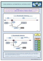
a) The VFO circuit
The basic version makes use of a Colpitts fet oscillator and a buffer (2N2222) driving the RX<br />
and TX circuits. It works very well up to 7 or 8 Mhz, above this limit the stability may be<br />
impaired, therefore if you want to adapt this transceiver for a highbands use (this is the case<br />
of 14 MHz band), it will be better to choose the conversion VFO version, wich makes use of<br />
the whole PCB board. You may shift from a version to the other simply by changing the<br />
connection of the C5 capacitor. The basic circuit version doesn't use the conversion<br />
components (located in the lower part of the schematic)<br />
Where specified, the capacitors must be NPO type. The tuning coil must be wound very<br />
carefully.<br />
A multiturn pot may be employed for the tune control, but this will make the building of a<br />
frequency reading scale more difficult.<br />
The L1 coil for the 14 Mhz band is made by 50 turns of enameled 0.40 mm wire wrapped on a<br />
13mm plexiglass core. The specified component values allow a frequency span of about 70<br />
KHz (from 2,433 to 2,510 Mhz) and the output level will be 4V pp. The two varactor diodes<br />
contained in the BB204 must be parallel connected.<br />
The L2 and L3 coils for the 14 Mhz band are obtained wrapping 12 turns of 0.50 mm<br />
enameled wire on a toroidal core T442. The link on L2 is made by 3 turns of plastic insulated<br />
wire.<br />
To tune this module you may follow these instructions :<br />
remove the 16 MHz crystal so as the oscillator goes off<br />
remove the connection between C21 and the gate 1 of the mosfet<br />
input a 18.4 Mhz signal to the gate 1 of the mosfet<br />
tune CV2 and CV3 capacitors for the maximum output at 18.4 MHz frequency, using an RF<br />
probe (or better an oscilloscope)<br />
insert the crystal and C21 capacitor<br />
turn RV1 at the minimum value and tune CV1 so as to obtain a 18,433 Mhz (14 + 4,433)<br />
frequency
) The Receiver circuit
It uses a classic superetherodyne design, employing mosfets in the front end and in the mixer<br />
stage, so as to obtain a good immunity towards overloadig signals and a few dB of RF gain.<br />
The XTAL ladder filter makes use of 4 crystals, it exhibits about 600 Hz of bandpass and a<br />
good outofband rejection. You may employ any set of crystals, provided that their frequency<br />
is near 4 MHz. An NE602 IC is used as a product detector, producing also the beat frequency<br />
by another (same frequency) crystal. A capacitor, series connected to the crystal, raises<br />
slightly the beat frequency, so producing the required shift to demodulate the CW.<br />
The BF circuit makes use of a first preamplifier and filtering stage followed by an AGC circuit.<br />
This BF automatic gain control partially compensates for the lack of a true IF section and the<br />
relative RF derived AGC. Please notice that the RX circuitry is working also in TX mode, so the<br />
trasmitted CW, whose amplitude is reduced by the diodes bridge and the AGC control, can be<br />
heard from the loudspeaker while keying (full breakin and monitor functions).<br />
An LM386 IC works as a power amplifier delivering about 1 W into an 8 loudspeaker. Be<br />
careful while connecting this IC on the PCB board, an effective ground bypass is needed for<br />
the Vcc supply line, I suggest to insert two 47 µF capacitors immediately near the IC pins (see<br />
C34 in the assembly schematic), also the connections to volume control must be shielded.<br />
The L3 coil is made by 30 turns of enameled 0.30 mm wire wrapped on a 5 mm plastic<br />
support with ferrite core, the tap is obtained at the 6th wire from the Vcc (cold side).<br />
The L1 and L2 coils, for the 14 Mhz band, are obtained wrapping 16 turns of enameled 0.40<br />
mm wire on a T442 toroid. The link on L1 is made by 3 turns of plastic insulated wire.<br />
To tune this module please follow these instructions :<br />
tune the mixer stage injecting a 4,433 Mhz signal into the VFO input and adjusting the L3<br />
core so as to obtain the maximum output from the T3 collector<br />
connect the VFO and input a 14 Mhz singnal to the receiver, then alternate the tuning of<br />
CV1 and CV2 so as to obtain the maximum output from the XTAL filter<br />
connect the antenna and adjust slightly CV1 and CV2 so as to obtain the best reception of a<br />
week signal<br />
you may change the CAG decay time by modifying the R24 value (the higher the value, the<br />
longer the decay time)<br />
If any instability is observed in the frontend stage, you may try to solve the drawback by<br />
parallel connecting a 470 to the RX input, and/or loading the L2 coil with a 1522 K parallel<br />
connected resistor.<br />
c) The Transmitter circuit<br />
See on the next page...<br />
Some QRP rigs...
It employs a frequency conversion design, so you can operate the TX and RX using a single<br />
VFO.<br />
An NE602 mixer converts the VFO frequency up to the 14 MHz band using a crystal similar to<br />
those used in the RX, the little series connected inductance lowers the crystal oscillating<br />
frequency so as to produce the necessary shift. The power broadband stage is equipped with<br />
a transitor suited for the CB band (2SC2092, 2SC1969, MRF475, 2SC2166). The driver and<br />
final transistors must be adequately cooled. The T1 transformer has a 1:4 ratio and is made<br />
bifilar winding 6 paired turns of enameled 0.5 mm wire on a ferrite TV balun (12x12 mm). A<br />
double Pi filter cleans the signal before sending it to the antenna, while a diode bridge works<br />
as an electronic switch and implements the full breakin function. The power supply to the<br />
driver stages is inhibited while receiving, by means of TR1.<br />
The 14 MHz coils must be made in the following manner :<br />
L2 and L3 : 16 turns of enameled 0.40 mm wire on a T442 toroid, tap at the 5th wire, link<br />
made by 2 turns of plastic insulated wire<br />
L4 and L5 : 12 turns of enameled 0.50 mm wire on a T506 toroid<br />
To tune this module connect the VFO, then alternate the tuning of CV1 e CV2 so as to obtain<br />
the max imum output (4 5 W) on a dummy load (you may build it by parallel connecting 9<br />
resistors 470 1W).
The full power current required will be about 1 A. If any instability is observed, you<br />
may try to solve the problem by inserting a low value (0.5 ) resistor series connected to the<br />
emitterof TR5, and/or by raising the R6 value to 100 or more.<br />
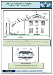
d) The PCB boards
e) some final notes<br />
The assembly is not particularly critical, however some care must be dedicated to the VFO<br />
and RX input stage, wich must be aligned carefully. The overall sensititivity and selectivity are<br />
very good, and so also the capability to handle strong overloading signals, in short the mixer<br />
and XTAL filter stages make well their job. Also the BF CAG system proved to be very effective,<br />
and the listening quality recalls a good IF system. Especially the CW envelope is very good,<br />
showing a very short attack and decay time.<br />
73's and have fun on QRP !<br />
IK3OIL, Francesco<br />
If you are interested in further informations,<br />
or to get the PCB masters, please contact<br />
me at my Email box.<br />
info@ik3oil.it<br />
http://www.ik3oil.it/<br />
HB9BQB's QRP rigs
Compact Bugout comm trailer<br />
By Ralph Fellows, W5FTV<br />
The devastation of Hurricane Katrina and the catastrophe of the greaterHouston mass<br />
evacuation for Hurricane Rita retaught me the necessity of advance, thorough disaster<br />
preparation. After considering mobility options such as a new diesel powered extended cab<br />
4WD truck, a small travel trailer, popup camper and more I settled on keeping my current 4WD<br />
Ford Explorer and adding a small cargo trailer. It seemed a reasonable cost choice which<br />
would enable me to move my small family and essential supplies on a moment's notice.<br />
I decided that one primary requirement for the trailer was that it must fit inside my attached two<br />
car garage. That would eliminate recurring offsite storage fees and ensure that the trailer<br />
would be protected from weather and instantly accessible no matter what the local conditions<br />
might be. To that end I purchased a new five foot by eight foot box cargo trailer with a single<br />
rear door. It fit inside my garage door only after I let some air out of the tires!<br />
At first, I envisioned simply keeping nonperishable supplies preloaded, and at the final<br />
moment, loading perishable and irreplacible items in the trailer. It didn't take long before I<br />
realized that the trailer had much greater potential. After a few brainstorming sessions it was<br />
decided to not only use the trailer for survival necessities but to add a few creature comforts<br />
and Field Day and realworld emergency amateur radio features.<br />
Outfitting was begun by removing the original ceiling, front and wall panels. A single layer of<br />
aluminum foilbacked foam insulation was installed in the front and two side walls while the<br />
ceiling was doubled insulated with the same material to increase protection against the oftblistering<br />
hurricaneseason Texas sun. Expanding foam was used to fill remaining inwall<br />
spaces and the original panels were then reinstalled.<br />
RV type rubberbased paint was applied to the roof. A rust inhibiting and moisture barrier oil<br />
based paint was used on the frame and bottom side of the trailer floor.<br />
Conventional water based white paint was used to brighten the interior. Steel gray<br />
deck and porch paint was chosen for the interior trim. Carpet donated by a friend was put down<br />
after the floor was coated with the deck and porch paint.<br />
Additional brake, running and turn lights plus reflectors and reflective tape were placed on the<br />
outside of the trailer to increase ontheroad visibility. A largish ABC fire extinguisher, major first<br />
aid kit, floor jack, jackstands, spare tire, lug wrench, chocks, emergency triangles, assorted<br />
flashlights, ultrahighintensity chemical light sticks, tire repair kit, pressure gauge, cannedair<br />
tire inflator/sealer and 12 VDC air compressor augment safety. Keyedalike high quality<br />
padlocks with spare keys were obtained for the door, battery box, interior bench seat and spare<br />
tire.<br />
To increase storage capacity it was decided to fabricate sideopening cabinets extending<br />
almost the entire length of both the left and right sides at the ceiling line. A rearopening door<br />
was included at the back of the right cabinet to facilitate storage of antennas and a telescoping<br />
fiberglass mast kept in capped PVC tubes. A shelf was placed above the PVC tubes. An RV<br />
pullhandle was installed on the rightrear of the left cabinet to aid in climbing into the trailer.
A cushioned, moveable bench seat/cabinet, to be normally stowed flush to the interior front wall,<br />
was also built. The cabinet interior was divided into two compartments. One for electronics with<br />
safety items and another for generator storage. Heavy duty handles were fastened to the<br />
cabinet ends to aid in moving the hefty assembly. A durable stained and polyurethane coated<br />
oak folddown table was installed to the left wall to accommodate meals, radios and such.<br />
Brackets were affixed to the right wall to stowe solar panels and two higherquality folding<br />
chairs. Care was exercised to not permanently fasten any fixtures to the floor so it could be<br />
used for sleeping with a queen size inflatable air mattress or sleeping bags.<br />
Colorcoded containers for gasoline and water stores were acquired along with energy bars and<br />
military style meals complete with chemical heater, entree, condiments, dessert, disposable<br />
utensils and drink mix. Gasoline is chemicalstabilizer treated and rotated at intervals. Water is<br />
also storage treated and rotated. A backup submicron water filtration kit and iodine purification<br />
ensure an adequate supply of safe drinking water.<br />
A hassock style toilet and extra chemicals were procured at a local camping store.<br />
A 5,000 BTU air conditioner was purchased from a "bigbox" hardware store. Two AC/internalbattery/external<br />
12 VDC powered fans were bought for their powersource flexibility.<br />
Provisions were made to employ power from external AC mains through a heavy gauge<br />
extension cord, a one KW gasoline powered generator, an onboard marine battery, six solar<br />
panels and DCtoAC inverters. A metal enclosure was welded for the marine battery and<br />
positioned just aft of the trailer hitch. Because the enclosure top was partially blocked by the<br />
spare tire two stainless piano hinges were installed. The front hinge allows fulltime access to<br />
storage in front of the battery while the rear hinge allows fullbox access when the spare tire is<br />
dismounted.<br />
Two combination AC/DC/RF panels were fashioned from aluminum diamondplate for exteriortointerior<br />
connections. An RVtype weather resistant AC receptacle was installed on the exterior<br />
panel with a corresponding hometype AC jack on the interior panel. A tenguage circuit was run<br />
from the panels to the interior of the left overhead cabinet to power the air conditioner and a<br />
multioutlet strip on the wall above the folddown table. Six inch UHF series "barrels" handle RF<br />
signals while Anderson powerpoles make the DC connections.<br />
Three conventional medium screwbase lightsocket fixtures were fastened to the underside of<br />
the left overhead cabinet for abovethetable lighting. Powermiser twelve volt multiLED lamps<br />
from Backwoods Solar were installed in the fixtures. A seven amphour gelelectrolyte battery in<br />
the left overhead cabinet provides morethanample power for the lighting.<br />
Doubleandtriplepair parallelconnected Anderson powerpoles were employed for all 12 VDC<br />
load and source cables. This configuration makes it possible to contiuously chain devices to the<br />
safety limit of fuses and wires. A four gauge black/red cable pair is used to connect the marine<br />
battery to the external AC/DC/RF panel and pass DC to the trailer interior. Ring terminals and<br />
stainless hardware permanently affix the cable to the battery. A short tengauge cable for<br />
connection to devices outside the trailer, such as the solar panels, is likewise affixed to the<br />
battery. Both cables' positive and negatives leads are protected by low resistance type AGU<br />
inline fuses located close to the battery terminals.<br />
The ham radio equipment includes a Yaesu FT817 "station in a backpack" and a Yaesu FT897.<br />
Both have interal batteries and can be powered by external DC. An Alinco DR620 provides the<br />
primary VHF/UHF capability. The firstline antennas are a 75/40 meter inverted V supported by<br />
a 30 foot fiberglass telescoping mast and a quater wave 75/40 meter NVIS wire. Band switching<br />
is accomplished by connecting or disconnecting double Anderson powerpoles to change<br />
radiating element lengths.
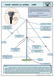
The inverted V can be set up quickly by placing the base of the fiberglass mast in one of two<br />
steel pipe sections welded vertically near the battery box. A Comet GP8 VHF/UHF vertical on<br />
three five foot TV mast sections can be similarly erected in the second of the two steel pipes<br />
near the battery box.<br />
Alternate antennas include a full set of Lakeview Hamsticks with matching coil/ incremental<br />
length whips and a Maldol HVU8 compact vertical for 80 meters to 70 cm. An MFJ904H tuner<br />
and MFJ831 artificial ground are employed during HF<br />
operation. The artificial ground is connected to the trailer<br />
frame and aluminum skin through a pair of green<br />
Anderson powerpoles on the interior AC/DC/RF panel<br />
and a length of onehalf inch braided lowZ wire. Quarter<br />
wave counterpoise wires can be connected to the trailer<br />
frame to enhance "ground tuning" for 75 and 40 meters.<br />
MFJ259B and AEA VIA analyzers are on hand to test<br />
antennas. An MFJ4416 battery booster is available to<br />
extend and improve performance when equipment is<br />
poweredby the marine battery. A 30 amp switching power<br />
supply is kept for opportunities when AC main power is available. A handheld GPS,<br />
band/frequency charts, owner's manuals, quick references from niftyaccessories.com, a<br />
repeater directory, road atlases and additional hardcopy aids are on hand. A digital multimeter,<br />
replacement connectors, interseries RF adapters, extra coaxial cable, tools, spare fuses,<br />
common small batteries, Dacron rope, "Gorilla" tape, wrist rocket wire launcher and other items<br />
round out the inventory.<br />
I'd like to extend my most sincere thanks to Bill Stevenson, K5CSB (carpentry) and his friend<br />
Larry Anderson (metal fabrication) for their generous and invaluable assistance with this<br />
project. Their pragmatic skills gave gave practical form to many a concept.<br />
73's W5TFV, Ralph
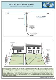
M aa kk i nn gg aa 22 88MH zz rr uu bb bb ee rr dd uu cc kk f oo rr t hh ee FF TT 88 11 77<br />
B yy A nn dd yy GØ FF TTD<br />
The main component in this design is the supporting rod, which the wire is wound upon.<br />
I was given two flexible rods by a friend. They are sold as garden rods, used to support flowers<br />
and plants. They also glow in the dark luminous! They are about 9mm in diameter.<br />
Unfortunately, I have not found a local supplier.<br />
The rod needs to be 530mm for the antenna, plus about 15mm, which is inserted into a PL259<br />
for RG8 style coaxial cable.<br />
CONSTRUCTION<br />
• Solder a suitable length of wire (7/02 guage, 1mm diameter PVC coating) into the centre of<br />
the PL259.<br />
• Insert flexible rod into the PL259 (it easily fits ok).<br />
• Now wind the correct amount of turns on to the 9mm rod, as shown in the diagram.<br />
• Then use PVC insulation tape as shown here<br />
• Add the PL259 bnc adapter.
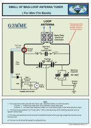
SWR and Tuning<br />
Firstly you must decide how you use your FT817.<br />
Either you hold it with your hand (like FIG ) or it is to be free standing. This is because the<br />
human body is part of the antenna, and must be considered.<br />
Check the SWR using the internal FT817 SWR meter.<br />
Trim the antenna wire by 5mm each time.<br />
WARNING the 5mm steps are critical, 5mm makes a large difference !<br />
You will also obtain different results when tuning indoors or outdoors you must decide.<br />
RESULTS<br />
FT817 internal chassis<br />
During the summer of 2006 I made some QSO's with it. Best DX was from GEA8, and<br />
ES/UA/IK/EA with ease. My QTH was by the seaside in Whitstable.<br />
I also discovered that the SWR is OK, if I sit down and hold the FT817 between my knee's. It is<br />
not a good idea to use the FT817 at the side of the body when using the carrying strap. There<br />
is too much attenuation by the human body.<br />
WARNING!<br />
It is easy to damage the FT817 with ANY antenna which is connected to the BNC socket.<br />
Always be careful with any antenna connected to the front BNC, or damage of the FT817<br />
internal chassis could result.<br />
I have included a photograph of an FT817 internal chassis, which is made of alloy / aluminium.<br />
It is not very strong. Be careful!<br />
Have fun Andy G0FTD
THE DX NEWS<br />
From the Web (tnx opdx, 425 dx news, arrl...)<br />
7P8, LESOTHO<br />
Ivan, UR9IDX, is expected to be (or is) in Lesotho and has received the callsign 7P8R. His<br />
length of stay is unknown, as well as his plans for operations (bands/modes) as this was being<br />
written. QSL direct only to: Ivan Borzenko, P.O. Box 85, Mari, Mariupol31, 87531, UKRAINE.<br />
8Q, MALDIVES<br />
Just a reminder that Nobby, G0VJG, will be active as 8Q7CQ between June 115th. This will<br />
be a limited operation because Nobby will be on his honeymoon (and he thanks his wife for<br />
putting up with him and the QRM). Activity will be from Kuredu Island (AS013) mainly HF SSB<br />
but some 6 meters. QSL via Owen, G4DFI. Visit his Web page at: http://g0vjg.piczo.com/?cr=5<br />
8Q, MALDIVES<br />
Tom, PF4T, will be active as 8Q7TB from the Island of Embudu between June 824th. Activity<br />
will be on 40 and 20 meters using SSB with a FT897 and G5RV antenna. QSL direct to PF4T<br />
or by the Bureau via PA0LEY. For more details on QSL info, see (QRZ.com). Also, visit his<br />
Web page at: http://8q7tb.pf4t.nl<br />
CY0, SABLE ISLAND (Attention Topbanders)<br />
Randy, N0TG, informs OPDX that the CY0 Sable Island Dxpedition team will incorporate the<br />
famous "Battle Creek Special" antenna for 160 meters as well as 80/40m. This was made<br />
possible by the generous loan program coordinated through George, W8UVZ. The team<br />
thanks this special group for their support for not only for their CY0 operation, but for the many<br />
DXpeditions down through the years. The dates of the DXpedition are October 1926th.<br />
operators are Randy/N0TG, Ron/AA4VK and Murray/WA4DAN. Visit their Web page at:<br />
http://www.cy0dxpedition.com<br />
E51, SOUTH COOK ISLANDS<br />
Nigel, G4KIU, is now active as E51SC from the Island of Rarotonga (OC013). He has moved<br />
to the South Cook Islands and is expected to be on 8010 meters mainly on SSB, RTTY,<br />
PSK31 and with some CW. He was heard this past week on 20 meters PSK31 between 0330<br />
0630z. Direct QSLs are to be sent to: Nigel Peacock, P.O. Box 880, Rarotonga, Cook Islands<br />
(via New Zealand). Please send a SAE, plus 2 USDs or 2 new style IRCs. Any direct cards<br />
received without the above items will be returned via the Bureau. Bureau QSLs go to: E51SC<br />
via G4KIU/RSGB. **IMPORTANT** There is no QSL Bureau in the Cook Islands. Cards<br />
without G4KIU on them will NOT be received. Please "DO NOT" send direct cards to any<br />
G4KIU address in England they will NOT arrive. All E51SC contacts will be loaded to LoTW<br />
about once a week. He does not use e.QSL at all.<br />
EI09, IRELAND (Special Event)<br />
Members of the Galway Radio Experimenters Club are now active using the special event<br />
callsign EI09VOR until June 6th. Activity is to celebrate the Volvo Ocean Yacht Race which<br />
takes place in Galway, Ireland. Look for both CW and SSB operations. Over the past week<br />
activity has been on 30/20/17 meters. Operators will be operating from Mutton Island<br />
Lighthouse. QSL via EI8DD. For more info, visit their Web page at:<br />
http://www.galwayradio.com
HF70/SN70/SO70, POLAND (Special Event)<br />
Look for members of the Polish Radio Amateur Associated (PZK) to activate the following<br />
special event stations during the 70th anniversary of the beginning of World War II.<br />
The "NO MORE WAR" stations will be on the air during various times between September 1st<br />
and October 6th. The following stations are:<br />
HF70NMW (by SP6ZDA) SN70N (by SP2CA) SO70R (by SP4NDU) SN70NMW (by<br />
SP4JCP/SN4L) SN70O (by SP8NFZ) SO70E (by SP4JAE) SO70NMW (by<br />
SP3ZIR/SN3B/SQJPV) SN70M (by SP9KN) SO70W (by SP5PPK/SQ5NAE) SN70R (by<br />
SP2YRY/SP2UUU) HF70N (by SP5KDK/SQ7HNT) SN70E (by SP1MWF) SO70A (by<br />
SP9YGD) HF70O (by SP2LQP) SN70W (by SP2LNW) HF70M (by SP8MI)<br />
SN70A (by SP2KMH/SQ2MMS) HF70R (by SP4ICP) HF70E (by SP5X) SO70N (by<br />
SP2AYC) HF70W (by SP2KDS/SQ2BXI) SO70O (by SP9KAJ/SP9CLU) HF70A (by<br />
SP5PSL/SP5JXK) SO70M (by SQ9JKD)<br />
MUSEUM SHIPS WEEKEND EVENT<br />
The "2009 Museum Ship Weekend Event" is sponsored by the "Battleship New Jersey<br />
Amateur Radio Station" and will be held next weekend, between 0000z June 6th, and 2359z<br />
June 7th. As this was been typed, some 76 museum ships are participating. For an uptodate<br />
listing of participating museum ships, frequencies and details on a certificate which is<br />
available, please visit:<br />
http://www.nj2bb.org/museum/index.html<br />
Activity will be on all HF bands, 8010 meters, using CW, SSB and PSK31. Some ships will<br />
also use Amplitude Modulation (AM) with either their ships original equipment or modern<br />
equipment.<br />
NEW AWARD AVAILABLE<br />
Francis, F6FQK, informs OPDX that a new TP2CE Radio Club diploma is now available<br />
called: "Council of Europe Radio Amateur Club Award". Complete rules and photos are<br />
available on: http://ewwa.free.fr<br />
OH0, ALAND ISLAND (Possibly OJ0)<br />
Manuel, CT1BWW (SWL CT0783), will be active as OH0/CT1BWW between July 26th and<br />
August 7th. Activity will be on 8010 meters using CW, SSB and RTTY. QSL via CT1BWW,<br />
direct or by the Bureau. Manuel may be active as OJ0/CT1BWW from Market Reef on August<br />
1st. For more info, visit Manuel's interesting Web page at:<br />
http://www.geocities.com/oh0ct1bww<br />
PA6, NETHERLANDS (Special Event)<br />
To celebrate the reopening of a 800 year old church tower (after its renovation) in Noordwijk,<br />
look for PA6JEROEN to be active between June 414th on HF and VHF. The old church is<br />
called "Oude of St Jeroenskerk" (in English: Church of St. George). Actual operations from the<br />
church tower will take place on two Fridays, June 5th and 12th. Pictures of this tower can be<br />
viewed on:<br />
http://picasaweb.google.nl/jaap.pa7da/OudeOfStJeroenskerkTorenbezoekNoordwijk#<br />
Please QSL only via the Bureau to PA7DA.<br />
ADDED NOTE: Jeroen (St. George) was a Monk from Scotland and arrived at the Noordwijk<br />
(Nortgho) in 847. In 857, he built a Chapel on the place of this Church and did bring<br />
Christianity to the people in the western part of Holland and West Friesland. Later he had<br />
been killed by the Normans!
PZ, SURINAME<br />
Mike, AJ9C, will be active from between October 2229th. His callsign will be announced when<br />
it is assigned. He is expected to be active on 1606 meters using CW, SSB and RTTY, as well<br />
as an entry in the CQWW DX SSB Contest (October 2425th). QSL to his home callsign with<br />
SASE/USD(s) for return postage.<br />
TK9, CORSICA (EU014)<br />
Members of the DXCiting Team will be active as TK9X between July 25th and August 1st.<br />
Activity will be on 1606 meters using CW, SSB, RTTY and FM. Operators mentioned are: YL<br />
Silvia/EA1AP, Alberto/EA1SA, John/EA3GHZ, Raul/EA5KA, Paco/EA5RU and<br />
Alicia/EA5EWM. QSL via EA4URE, direct or by the Bureau. Visit their Web page at:<br />
http://www.dxciting.com/tk9<br />
U.K. TRIP<br />
Bruce, ZL1AAO, informs OPDX that he is going on a "DXing and nostalgia trip to the UK for<br />
exGM1KNP". He wants to advise DXers and friends that he will be touring in the UK during<br />
July and August. Bruce will be using the UK country prefixes followed by his New Zealnd<br />
callsign (e.g. MM/ZL1AAO when in Scotland). He expects to be in Scotland, England and<br />
Wales (as he holidays around) and hope to include some activity from the Orkney Islands.<br />
Activity will be limited to mobile/portable operations using a FT857D, multiband vertical or a<br />
tuner with longwire. Mode will be SSB only. He will produce a special QSL celebrating his<br />
activity. Check (QRZ.com) for some more details and updates when he has more specific<br />
plans. QSL via his home callsign.<br />
VP9, BERMUDA<br />
Alex, W5YDX, will be active as VP9/W5YDX between June 1024th. Activity will be holiday<br />
style (during his spare time) mainly on 20 and 17 meters (suggested freqs. between 14140<br />
14265 kHz) using 100 watts into a dipole. QSL via W5YDX.<br />
ZD8, ASCENSION ISLAND<br />
Dean, KJ4GNB, is now active as ZD8DC. His length of stay was not known as this was being<br />
typed. Activity so far has been on 20 meters SSB. QSL ZD8DC via KJ4GNB.<br />
ZK2V NIUE OPERATION UPDATE<br />
Chris, ZL1CT/GM3WOJ, provided OPDX with the following operation update: "A quick update<br />
from ZK2V made 6100 QSOs in 9 days, which is a bit disappointing conditions poor,<br />
especially last weekend. Made only 1 QSO on 160m and 2 QSOs on 80m, so concentrating<br />
on the higher bands. Openings to Europe are often short with weak signals, which is lowering<br />
the QSO rate, but signals from JA and the USA have been strong. Will be on RTTY tomorrow<br />
(28th May) for about 30 mins sometime between 0600 and 0800 UTC (14082 approx QSX up<br />
8) will do more RTTY if things work well.<br />
For the first time from Niue, I have a special permit to operate on 60m from 0000 Niue time<br />
(= 1100 UTC) on 1st June 2009 until 0000 Niue time (=1100 UTC) on 8th June. I can transmit<br />
*only* on 5403.5 kHz (USB for USA, but CW for rest of world), but will listen on 5371.5 or<br />
another channel. The website www.zk2v.com is updated nearly every day there is an online<br />
logsearch and all QSOs are uploaded to LoTW every few days. ZK2V is QRV for 25 more<br />
days and hoping for better propagation. QSL direct or via the bureau to N3SL (not ZL1CT)."
DXCALENDAR<br />
By SM3CVM<br />
http://www.sk3bg.se/<br />
30/5 TOGO; 5V7PM<br />
by DL9MBI. Activity over the past weekend was on 20 meters, SSB, RTTY and PSK. QSL via<br />
his home callsign by the bureau. For direct cards, please send QSL cards to: Werner Peter<br />
Mueller, Plattenberg 2 1/2, D84508 Burgkirchen, GERMANY (w/SAE and two green stamps.<br />
Otherwise the answer will be via bureau).<br />
30/5 DOMINICAN REPUBLIC; HI7/OT4R<br />
from Punta Cana. Activity will be on 20/15/10 meters SSB. Suggested frequency for 20 meters<br />
maybe 14300 kHz. QSL via OT4R.<br />
30/5 ALASKA; N6IC/KL7 NA041<br />
from Douglas Island during a family visit. QSL via home call.<br />
31/5 UGANDA; 5X4X<br />
from Arua by DL8SBQ. He runs 100 watts into a spiderbeam for 20, 17, 15, 12 and 10 metres<br />
and a Zepp antenna for 40 metres. He has been pirated on 160, 80 and 40 metres if you<br />
worked him during the evening hours, please note that Peter cannot operate after 20 UTC,<br />
because the power is off in Arua. QSL via DF5GQ.<br />
31/5 CANADA; XL, XN, XM,and XO<br />
Celebrating the 50th anniversary of the opening of the St. Lawrence Seaway, Canadian<br />
amateurs are allowed to use the following prefixes: XL (VA stations), XN (VO stations), XM<br />
(VE stations), XO (VY stations).<br />
31/5 CANADA; XOØICE/2<br />
by VE2TKH will be active from Quebec City to celebrate the 50th anniversary of the entry in<br />
service of the St. Lawrence Seaway. QSL via LoTW only (paper QSLs will not be available).<br />
2/6 TANZANIA; 5H1HP and 5H1MS AF032<br />
from Zanzibar by DL2NUD and DL9MS. Activity will be on the HF bands and 6 meters, but an<br />
emphasis will be on VHF (EME/MS). Grid squ<strong>ares</strong> to be activated are: KI93RU and KI94RA.<br />
3/6 NEW CALEDONIA; FK/G4JVG OC032<br />
from Noumea by 9M6DXX (G4JVG), holiday style while celebrating his 25th wedding<br />
anniversary with 9M6EVA. Activity will be SSB only, using 100 watts to 'fishing rod' verticals on<br />
40, 20, 17 and perhaps 15 metres. QSL both operations via MØURX, direct or bureau. The<br />
logs will be uploaded to LoTW.<br />
15/6 JAPAN; 8N5I AS076<br />
from Shikoku Island during the 2009 Shikoku Info Telecom Month. QSL via JARL bureau.
20/6 BANGLADESH; S21XR<br />
with new call (earlier S21UGZ) from Dhaka by DU1UGZ. He operates in his spare time using<br />
a low band dipole. For the time being, he will focus on 40 and 80 metres SSB and RTTY, but<br />
in May he should get a beam for 10, 12, 15, 17 and 20 metres and hopefully a linear amplifier<br />
as well. QSL via home call.<br />
20/6 NIUE; ZK2V OC040<br />
by ZL1CT. His 5week expedition aims to give as many stations as possibile their first QSO<br />
with ZK2. Resources are limited, and he will operate mainly on 80, 40, 20 and 15 metres CW<br />
and SSB, with some activity on 30, 17 and 12 metres and some RTTY. QSL via N3SL. A logsearch<br />
will be available at http://www.gm7v.com/zk2v.htm, and he plans to update it as often<br />
as possible.<br />
1/7 CHAD; TT8CF<br />
by F4BQO. He plans to operate CW and SSB on the HF bands. QSL direct to F4BQO.<br />
20/7 JAPAN; 8J<br />
Ten special event stations (8JØ4ØM8J94ØM) from each callsign district of Japan will be<br />
active between 16 May and 20 July to celebrate the expansion of the 7 MHz band in Japan.<br />
QSL all stations via the JARL bureau.<br />
24/7 NIGERIA; 5NØOCH<br />
by DL3OCH. He plans to operate EME and on the HF bands (16010 metres). Hopefully he<br />
will also go and operate from IOTA group AF076. QSL via DL3OCH.<br />
31/8 HONG KONG; VR2/F4BKV AS006<br />
mainly on PSK31 with some SSB during good propagation openings. His web site is at<br />
http://www.f4bkv.net/<br />
30/9 CROZET I.; FT5WO AF008<br />
by F4DYW says he will be working at Alfred Faure Base on Ile de la Possesson. He plans to<br />
operate on 20, 15 and 40 metres SSB during his spare time, using 100 watts and dipoles.<br />
QSL via home call, direct or bureau. Look for updates on<br />
http://f4dyw.free.fr/index.php?langue=fr&contenu=ft5wo.html<br />
31/10 JAPAN; 8J6SL AS077<br />
from the Kumamoto Museum to celebrate the 100th anniversary of Hisatsu (Railroad) Line<br />
(Steam Locomotive) on the Island of Honshu (JIIA AS077001). Activity will be on all bands<br />
and modes. Possibly 5 stations will be on the air. QSL via the JARL Bureau.<br />
1/11 ANTARCTICA; VKØBP AN016<br />
is currently working at Antarctic Davis Base Station, Gridsquare MC81xk. His activity is limited<br />
due to his workload, but he is expected to be on all HF bands. He seems to like 20 meters<br />
between 15001800z. Operations have been on SSB and PSK31, but he plans to operate on<br />
other modes later on during his stay at the Davis Station. QSL via VK2CA. PLEASE NOTE:<br />
There is also a possibility of activating other field huts in the area, and he will sign as<br />
VK0BP/P. Look for more details on his Web page at http://www.vk0bp.org/
OSCILLATING DAMPED WAVES<br />
Prof. Arthur BLAVE Ir, ON4BX<br />
Email: on4bx@tvcablenet.be<br />
By<br />
R L C CIRCUIT<br />
Vc
1. History.<br />
The waveform of the discharge of a capacitor into an inductive load has been well known for<br />
years.<br />
Trains of damped radio telegraphic waves made by a damped waves transceiver<br />
In the past, radio transmitters were using such technique to generate bursts of waves, then<br />
modulated by cw and later by microphone. Before the discovery of the first electronic tube, that<br />
was the only way to communicate by rf!<br />
A high voltage driving a spark could so generate bursts of damped waves into a coil, coupled to<br />
the antenna circuit..<br />
Example of a radioelectric<br />
arc transceiver<br />
Example of a radioelectric<br />
& radiotelephonic arc transceiver<br />
TheTitanic ship was using such circuits to generate radio waves of 600m of wavelenght for its<br />
radiocommunications.<br />
This is just the opportunity to invite the reader to consult the historic pages called « ondes<br />
amorties » into the wellknown encyclopedia « WIKIPEDIA »<br />
http://fr.wikipedia.org/wiki/accueil<br />
Of course, the discovery of the triode has conducted to the construction of radiotransmitters of<br />
highpower and spark waves generators are now museum pieces…
2. CALCULATIONS<br />
Actually, damped oscillating waves into a circuitry means usually problems of spurious, even or<br />
damage to the semiconductors. We must say that at the present time, damped waves are<br />
usually not welcome.<br />
But how to reduce their effect, more what can we do ? How can we interact with the elements<br />
of the circuit ?<br />
Usually, if we have a physical idea of the processus, the exact calculation is not well known.<br />
That is why I have written the full mathematical way to calculate a damped wave and where to<br />
interact to reduce<br />
it’s level. So we will be able to select the best choice of components, wiring, and how to dispose<br />
them in the chassis…<br />
2.1. First of all… A damped circuit may never been calculated via the conventional filters RLC<br />
theory.<br />
Those calculations are correct only if the circuit is on stationary state. That means that you can<br />
then make all tests via generators, meters etc… Your results are independant of the time.<br />
A damped wave is never in a stationary state ! Voltages and currents are always varying with<br />
the time. More, we are always sure that after an amount of time, the initial charge will be zero!<br />
the damped wave is over!<br />
That is why we must calculate all using mathematicals fonctions like derivation, complex<br />
formulations including complex exponentiations. They will also use some complex<br />
trigonometrics equations<br />
The capacitor has been charged via an external supply, removed when C is fully charged, into<br />
a stationary state. When we close the switch (at t=0), that voltage is applied into the inductance,<br />
associated with it’s resistance.<br />
A damped wave will start (probably!) as shown on the oscillogram.<br />
We will study the waveform of the voltage capacitor during it’s discharge into R.<br />
Of course, the initial charge of the capacitor will decrease, will never stay into a same state and<br />
after some time, will be fully discharged. That is the end of the damped wave.<br />
We will see later that depending of the value of the components, the waveform may be<br />
different… Even not present !
Calculation of the exponentials is now very difficult when the R L C are fully independants..<br />
To be able to go further, we will now accept that our circuit is of good quality. That means that<br />
the total resistance R in the circuit is quite low and that the inductance L is of good quality, with<br />
low losses.<br />
We have now to fix the values of the constants A and B. A and B are constant so we may try to<br />
fix their value at any instant of the damped wave. The value t = 0 is specially interesting.<br />
We know that in our physical circuit are inductance components. Even if the value of the coil is 0<br />
(L=0!!) there are wires between the elements so even very small, there is always a positive<br />
value present under L. So at t=0, the current is still 0. The voltage has not yet started to<br />
decrease so d(V) / d(t) must be 0. We will calculate it and apply the values to 0
COMMENTS :<br />
1. This calculation is only correct if we assume that we are close to a good circuit ! ( 2
that means a immediate breakdown! You must install a protection circuit around your semiconductors<br />
to protect them of those reverse voltages. Damping waves in high power system is<br />
frequently causing lots of trouble, moreover when attention has not been paid for them!<br />
5.May I suggest the reader to try some experiments and generates such damped waves?<br />
The capacitor may not be polarised. (voltage oscillating over and under zero volt).<br />
It can be charged via an auxiliary DC power supply with a serial resistor to permit the charge<br />
,but high enough to avoid any perturbation during the generation of the damping wave.<br />
Usual low voltage can be used as charging voltage.<br />
To display the wave, a memory scope can be connected at the capacitor. It will be selected as<br />
single trace, triggered by the capacitor voltage itself.<br />
A nonmemory conventional scope can also be connected but you will probably design your<br />
circuit for slow damping waves, or with a long persistence scope if any….<br />
If you do those tests, you may have some problem with the shorting switch!! Conventional<br />
switches have a usually a bounce of the mobile contact during the mechanical commutation. So<br />
there are a few interruptions before the contact is really fully fixed. If the duration of that bounce<br />
is close to the pseudoperiod of the damping wave, you may see something like stroboscopic<br />
effects! The display may be fully distorded!<br />
The only correct way is to use a small mercurywetted relay. Due to the capillarity, there is a<br />
mercury bridge between the moving and fixed electrodes during the mechanical commutation of<br />
the reed switch. There is no bouncing at all and the switching is perfect.<br />
6. Note: For more complex calculations, see also into the book<br />
“Reference data for radio engineers”<br />
(published by Howard W. Sams & CO.,inc ITT)<br />
73's from ON4BX
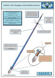
Chuck Blaney<br />
WW2 radio operator & prisoner of war<br />
A WINDOW IN TIME.... is the story of a B24 bomber crew<br />
that formed up at Mountain Home Air Base, Idaho, in 1944;<br />
shipped over to England where they were stationed at<br />
Seething Air Base; flew the first combat mission to<br />
Eurskirchen, Germany on Christmas Eve 1944; got shot<br />
down exactly three months later while bombing a target<br />
near Hamburg; were held prisoners and repatriated at war's<br />
end and reunited at a 50th anniversary reunion celebration<br />
set up by a German who saw the bomber crash while he<br />
was serving in the Hitler youth Corps.<br />
This was an episode in the life of Charles W. "Chuck"<br />
Blaney. He was the Radio Operator/Top Turret Gunner<br />
aboard the B24 bomber named "Do Bunny" shot down 25<br />
March 1945. Chuck Blaney was born in Chicago in 1925.<br />
His father worked for Pullman Co. converted from making<br />
railroad cars to making Assault Landing Craft during the war years. His motherget thiswas<br />
a "Rosy the Riveter" in a Chicago Ford Plant converted from autos to assembling B24<br />
Liberator bombers. Chuck enlisted in July 1943 and volunteered for the Army Air Corps. He<br />
completed his Radio Operator/Mechanics Training Course at Sioux Falls, South Dakota, and<br />
Gunnery School at Yuma, Arizona. Following crew formation at Lincoln, Nebraska, they went<br />
to Combat Crew Training at Mountain Home Air Base, Idaho. They were then sent to Topeka<br />
Air Base, Kansas for combat assignment and were selected to become part of the 448th<br />
Bomb Group, Eighth Air Force in England. In November 1944 the crew left Fort Dix. New<br />
Jersey and embarked on a sea voyage to Liverpool, England and moved to Seething Air Base<br />
as part of the 713th Bomb Squadron.<br />
Following the war, Chuck earned his BSEE at American University in Chicago and spent the<br />
next 30 years with several aerospace companies in various defense related engineering<br />
positions. Chuck ended his career as Manager of Product Marketing for Northrop/Grumman<br />
Aircraft Corp. after 23 years of service. Chuck is an Associate Member of the Colorado<br />
Springs Chapter of the Daidalians. He is also a life member of the American ExPrisoners of<br />
War and the American Disabled Veterans.<br />
Here is Chuck's story:
A WINDOW IN TIME<br />
By Chuck Blaney<br />
The date was the 25th of March 1945 and the target was<br />
the underground oil facilities at Buchen, Germany (about 6<br />
miles east of Hamburg). The 448th could have easily stood<br />
down this day. Yesterday's costly mission took a toll of<br />
eight B24's that were lost to ground fire when we<br />
dropped supplies to 40,000 British paratroopers that had<br />
just crossed the Rhine River at Wesel, Germany. This was<br />
a specially designed mission that took us over the<br />
battlefield at 100 feet for a parachute drop of medical,<br />
food, ammunition and a Howitzer Cannon that was stowed<br />
in the cavity where the ballturret had been removed.<br />
The Crew<br />
Admittedly, this was not a great mission for the high flying B24. So much for low level missions<br />
using the heavy bomber. After 2 hours of forming we departed Seething Air base at 0600 as a<br />
28 plane formation. We were on our 23rd combat mission with only 7 more to go before being<br />
rotated back to the states. Severe weather over the North Sea resulted in one squadron<br />
becoming detached from the rest of the 448th Bomb Group. However, the remaining 20<br />
bomber formation proceeded to the designated target. As expected, flak was experienced over<br />
the Dutch coast and again around the target area. The bombrun at 20,000 feet was successful<br />
and the target was destroyed with precision.<br />
At bombsaway the formation was attacked by a swarm of ME262 jet fighters. Coming out of<br />
the sun, the world’s first jet aircraft concentrated on our below strength bomber group. This<br />
would prove to be a costly day for the 448th. Four bombers would be shot down over Germany<br />
and two would manage to make it home only to be written off as salvage.<br />
ME262 fighters attacked Lt. Steffan’s B24 and the bomber blew up in midair. Only the<br />
Navigator, Lt. Gottlieb, was blown free from the nose and managed to open his chute. He was<br />
the sole survivor of this nineman crew. He was captured and taken POW. On the next fighter<br />
pass Lt. Stallard’s B24, our lead bomber with the radar bombing equipment, was strafed<br />
across the flight deck. The attack killed or seriously wounded several of this twelveman crew,<br />
including both pilots. Within seconds the plane went into a tight spiral to the ground. The right<br />
wing and then the other wing broke away from the fuselage. The plane then exploded and<br />
eventually crashed into a shoe factory in the town of Schneverdingen. Only three of the crew<br />
managed to bail out and survive as POW’s. They were Lt, Whitson, Pilotage navigator, Lt.<br />
McHugh, Bombardier, and S/Sgt Glass, the Radio Operator. Lt. Todd’s bomber was mortally hit<br />
and did a right turn north for Sweden. The plane managed to get to the Swedish coastline and<br />
ditched in the Baltic Sea. Seven crewmen, all but the pilot and copilot, survived. They were<br />
interned in neutral Sweden for the duration of the war.<br />
Our B24, Do Bunny, piloted by Lt. Paul Jones, immediately took extensive damage including<br />
the loss of one engine on fire. The engine was subsequently feathered and the fire<br />
extinguished. We maintained formation until a second ME262 pass on the squadron. This time<br />
we responded with all four gun turrets blazing 50 caliber bullets. However, we took several<br />
more 20 MM cannon hits, including the loss of a second engine that proved be fatal. Time<br />
seemed to stand still. The flight engineer was knocked out of his top turret and he dropped to<br />
the flight deck. The Plexiglas in the rear turret shattered in the tailgunner's face. Fuel and<br />
hydraulic fluid from pierced pipe lines were pouring and swirling out of the still open bomb bay<br />
which we were never able to close. Do Bunny was in real trouble.
After the second fighter pass we were forced to<br />
drop out of formation. We began a gradual<br />
decent to lower altitude. Jones ordered all<br />
crewmen to prepare for bailout. He also<br />
instructed the crew to lighten the aircraft. We<br />
threw out everything that was not nailed down <br />
flak suits, oxygen bottles, ammunition, the waist<br />
guns, and even the radio equipment.<br />
Our navigator, Lt. Herman Engel, could see the<br />
heavy clouds of smoke caused by our heavy<br />
bombing in the Hamburg area. He was able to<br />
set a coarse towards Wesel on the Rhine where<br />
the British Paratroopers had landed just the day<br />
before. I guess that we never really expected to<br />
make the Rhine but we did not have many options to consider. We were 220 air miles from<br />
friendly territory and we had flown about 50 miles in our crippled condition. Then a third<br />
engine over heated and had to be feathered. It was now evident that Do Bunny was not going<br />
to make it back.<br />
On our sixth mission we had experienced an emergency landing with our skipper at the<br />
controls. We had been on a typical bombing mission to Worms, Germany when we lost a<br />
single engine to flak over the target and a second engine became marginal. Jones maintained<br />
formation until we were over friendly territory. Rather than risk the 120 mile run to England<br />
over the icy North Sea, he elected to make an emergency landing. We landed on the only<br />
runway we could find, which was a PSP mesh fighter strip on the outskirts of Brussels,<br />
Belgium. Needless to say, we ran out of this short runway in a hurry and settled in the Belgium<br />
countryside. Our B24, Pregnant Lady, was written off as salvage as two engines were<br />
completely burnedout during landing. The successful emergency landing was a great<br />
confidence builder for the crew and especially for our pilot. We were indeed grateful for his<br />
judgment and piloting skills. The crew had all discussed how difficult our chances of survival<br />
might be should we have to bail out over enemy territory. In those days, late in the war when<br />
the conflict was going badly for the Germans, the civilians and certain military personnel like<br />
the SS and Gestapo were reported to be killing downed Allied airmen. This fact came straight<br />
from our Air Force Intelligence at mission briefings. The best chance, if possible, was for the<br />
crew to stay together as a group with the hope that the Luftwaffe or the regular German Army<br />
would take prisoners of war. This previous emergency landing had a great deal to do with the<br />
decision to ride out any subsequent crash landing in enemy territory. Another primary factor in<br />
our current situation was the extreme low altitude reached after we lost the third engine. It<br />
appeared doubtful that we could survive a bailout under all of these conditions.<br />
Lt. Jim Mucha, our copilot, selected a suitable flat area<br />
directly along our flight path to set down our crippled B24.<br />
We landed wheelsup in a field only 500 yards from<br />
downtown Soltau, Germany. Jones struggled with the controls<br />
just to keep the wings level. The crew had assumed its<br />
ditching positions. All went well until a wing dipped into the<br />
ground as we lost speed and then all hell broke loose. When<br />
that happened the plane just broke apart.
The three crew members in the waist, the tail<br />
gunner, the waist gunner and the ball turret gunner<br />
were able to jump out of the plane onto the<br />
ground. The cockpit was split wide open so the<br />
pilot and copilot were able to crawl out of the<br />
wreckage. All five were immediately confronted by<br />
angry town folk with pitchforks. Then two SS<br />
Officers appeared on the scene and the five were<br />
run into town and up against the wall of the Mehr<br />
Hotel. They were eventually taken control of by a<br />
German Officer in the Wehrmacht Army who was<br />
in charge of the Soltau Riding Academy. He had his soldiers and the manpower to take control<br />
over the civilians and the SS. He took the crew to the Riding Academy and locked them in the<br />
stables.<br />
The remaining four of the crew, the Navigator, Flight Engineer, Nose Gunner and I, the Radio<br />
Operator, were trapped on the flight deck and still in the wreckage. We were pinned there<br />
when the top turret broke away from the airframe and lodged in the flight deck well. The<br />
Navigator and the Flight Engineer were unharmed and finally got out after German soldiers<br />
axed their way into the fuselage. The Nose Gunner and myself were not so lucky. The top<br />
turret had pinned our legs which were broken. The soldiers, including the town Burgomaster,<br />
spent considerable time and effort to hacksaw and pry the top turret enough to set us free.<br />
They put us on a horse drawn cart and took us to the town hospital where our legs were set<br />
and put in soft casts. We then rejoined the other crew members that were now locked up at<br />
the Riding Academy. The next morning troops from the German Luftwaffe arrived from a<br />
nearby ME262 air base took over. Lt. Grauenhorst, the Riding Academy Officer, was relieved<br />
because he had been worried about the SS Officers and his confrontation with them the day<br />
before. We stayed at the air base one night and were then transported to Penneberg, an<br />
interrogation center for captured airmen. After four days in single solitary cells (the kind of stuff<br />
you see in movies) we were taken to Hamburg and shipped in railway boxcars, with other<br />
recently captured airmen, to Stalag Luft I Prison Camp in Barth, Germany. To this day, my<br />
copilot, Jim Mucha complains about having to carry me on his back through Hamburg but I<br />
counter by reminding him that I took all of the rocks thrown as we were paraded through the<br />
streets.<br />
In late May 1945, the Russians liberated our prison camp. Just before the Russians overran<br />
the area the Prison Commandant ordered an evacuation and forced march of all prisoners.<br />
Colonel Zemke, our senior camp officer, refused to give the order to march. The next day<br />
revealed that the German guards had fled during the night and left us to our own device.<br />
Colonel Zemke, along with Lt/Col. Gabreski, went out to meet the Russians to make sure that<br />
they didn't mistake our camp for a German area and shoot up everything in sight. These<br />
Russian troops were the advanced units with a search and destroy mission. Our senior<br />
officers made arrangements with the Russians to contact the Eight Air Force and advise them<br />
of our situation. It was then just a matter of time before the 8th Air Force flew into the airfield in<br />
Barth to get us the hell out of there. All 7,717 American Airmen from Stalag Luft I were flown to<br />
tent cities in France to join 90,000 other liberated Americans to await transport back home.<br />
Some prisoners had been incarcerated for nearly four years during the US Army Air Corps<br />
1,000 day War over Germany.<br />
A young 12 year old German boy, who was a member of the Hitler Youth Corps, watched our<br />
crash landing. Gerhard Bracke was that boy's name.
Today Mr. Bracke is a University Professor and a part time WW II aircraft<br />
historian. It was during this past year that he made it his goal to find out<br />
what happened to the crew in the bomber that he watched as it crash<br />
landed. Many of the details, that we never knew from the German<br />
viewpoint, were revealed by Brache's research. He was instrumental in<br />
locating the survivors of that crash still living today, and brought us<br />
together for a 50th anniversary reunion in Dayton, Ohio during the fall of<br />
1995. Gerhard Bracke flew in from Germany to join us for the<br />
celebration. The German Officer in charge of the Soltau Riding<br />
Academy was a Lt. Joachim Grauenhorst. He watched our B24 pass<br />
directly over the academy and thought it would explode any minute. But<br />
there was no explosion nor any sound of any crash so he assembled<br />
several soldiers and took off to find where the bomber had gone down. In<br />
locating the wreckage, he directed all his attention to freeing the trapped<br />
crewmen inside. He then went into the town square where the others<br />
were herded. An SS Officer was inciting the angry German civilians and<br />
Lt. Grauenhorst initiated an argument with the SS Officers as to who had<br />
the authority to take the prisoners. It was probably only because<br />
Grauenhorst had several soldiers with him under his command that he was able to take those<br />
crew members back to the Soltau Riding Academy stables. He probably saved all of our lives.<br />
The reunion in Dayton was a huge success. Gerhard Bracke arrival from Germany was a<br />
complete surprise. Of the nine original crewmen, five are still alive. Four of us made it to the<br />
reunion; Paul Jones, the pilot; Jim Mucha, the copilot; Herman Engel, the navigator; and me<br />
the radio operator. Mr. Bracke brought additional information he had gathered on our crew<br />
such as the official missing crew reports from other bombers that had seen the four bombers<br />
of the 448th Bomb Group go down that day. Bracke also had the biography of the German<br />
pilot, a Lt. Rudolf Rademacher, who shot us down. Rademacher had 118 victories in the ME<br />
109 and 8 more in Luftwaffe's hottest jet, the ME262 ( At least we were not shot down by an<br />
amateur). Lt. Rademacher survived the war only to die in a glider crash in 1953 about 10<br />
miles from where we crash landed. Poetic justice.<br />
Bracke also brought a personal letter from Lt. Grauenhorst who still lives in Soltau and a letter<br />
from the Mayor of Soltau inviting our crew to a City Of Soltau reunion in 1996.<br />
A highlight of Bracke's research was his uncovering of five photos of our<br />
crashed bomber that laid in the archives of the Soltau newspaper since 1945.<br />
What a treasure to acquire after all these years.<br />
So, that is my story. Four planes shot out of the sky in minutes and only our<br />
Lt. Rudolf<br />
Rademacher<br />
the German<br />
pilot that<br />
downed our<br />
plane on<br />
March 25,<br />
1945.<br />
crew survived intact. With hundreds of holes in our B24, no one was<br />
seriously wounded or killed. Why didn't the plane burn or explode in flight or<br />
upon crash landing. Was it just luck or was God the "tenth man" man in our<br />
crew that day. I would like to think that he was.<br />
The Crew:<br />
Paul Jones Pilot Owensboro, KY James Mucha Copilot McDonald, PA <br />
Herman Engel Navigator Brooklyn, NY Charles Blaney Radio Operator / Top<br />
Turret Gunner Chicago, IL Leonard Dailey Flight Engineer / Top Turret<br />
Gunner Beaumont, TX Albert Bentley Ball Turret Gunner Atlanta, GA <br />
Edward Danicki Tail Gunner Milwaukee, WI Alvin Stout Waist Gunner<br />
Arvada, CO William Wilson Nose Gunner Willamston, SC<br />
More informations here : http://www.merkki.com/<br />
Lt. Joachim<br />
Grauenhorst, a<br />
Wehrmacht officer<br />
assigned to the<br />
Riding Academy at<br />
Soltau
COMIC'S <strong>HAM</strong><br />
Have some fun<br />
To win this new rig<br />
IC7700, just call us on<br />
phone !<br />
Yes, there is an antenna<br />
on this photo !<br />
THE QSL OF THE MONTH