Untitled - Les Vieux Deb's
Untitled - Les Vieux Deb's
Untitled - Les Vieux Deb's

Create successful ePaper yourself
Turn your PDF publications into a flip-book with our unique Google optimized e-Paper software.
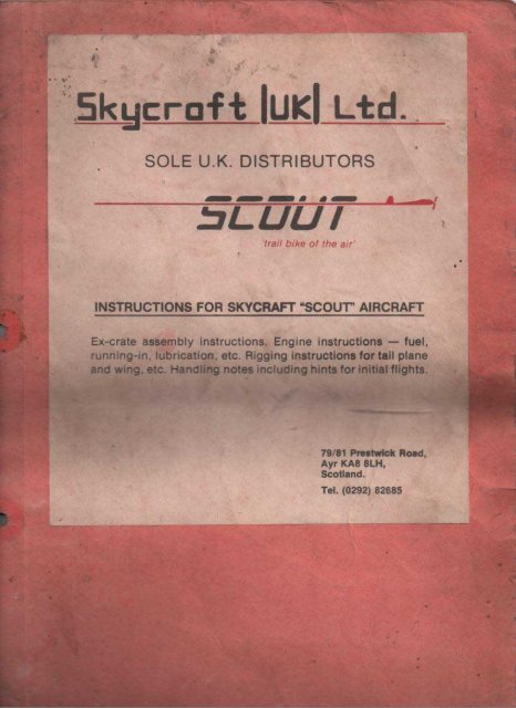
SKYCRAFT "SCOUT" AIRCRAFT - EX-GRATE ASSEMBL y INSTRUCTIONS<br />
Remove fabrics and wi.ng spars From cr-ate, Carefully remove the fuselage<br />
and its sub-'~ssembties, which are connected by the control cables.<br />
DO NOT REMOVE NUTS, BOLTS, WASHERS, ETC. From ANY component<br />
unti.t you are ready for the assembly of that particular art. DO NOT<br />
REMOVE the terylene lanyards From the rudder control cab es.<br />
With the fuselage upright and the cyl inder head resting on btock, erect the<br />
king post at "A" (Fig. 1). Refer to Fig. 2. Assemble the orward top éables<br />
as shown at "B". Push down on the fuselage, as indicat d, and assemble<br />
the aft top cable, as shown at "B".<br />
For ease of assembly, tt is recommended triat the fard end of the<br />
fuselage be suspended about four feet above floor l eyby mean or-a r-ope,<br />
Assemble the vertical A-frame truss (ref. Fig. ,. n~uding ~e landing<br />
wheels springs and the forward °brace cables, a sh , and attach to the<br />
fuselage at "c" (Fig. 1). CI'<br />
Raise the vertical column and fus)kage a "0". Make sure<br />
that the control cables are not twisted arou the colum •<br />
Enter- the forward end of the tor-que tube . to ~ spigo bearing and attach<br />
the horizontal struts to the axle beam at I~" ~d "~", engaging the .footrest by<br />
means of the same bolt s , Refer to ass mb detait ig. 4 •<br />
...<br />
Remove the nyloc nut and washer at 1 F" on Fig. and assemble the rear<br />
end of the horizontal strut, as show. • DO NOT VERTIGHTEN the nyloc<br />
nut.<br />
Dismantle the turnbuckle on the ~Q aft c le and assemble the eyebolt<br />
and turnbuckle half at "G" (Fig 1) heck 5 rward cables and top and<br />
bottom aft cables to ensure th t tare t twisted, as shown in Fig. 5.<br />
Re-engage the turnbuckle ev nl;( ~ nd sc w to tighten until both top and<br />
bottom cables register ten on~pply t ree or four more turns to the turnbuckl<br />
e , DO NOT OVERT ~N. Se ure the turnbuckle lock n..Jtsand<br />
lead up the safety wire, 0 to eng ge both fork ends and the centre secti.on,<br />
as shown. .<br />
Assemble the inciden e ba'-7at "H', Fig. 1.<br />
The steel shackle- a~ shoul be fitted on top of the fuselage with the hole<br />
towards the rear. 0 give cle ance for fixlng the elevator drag wire<br />
shackle, twist th steel shac e-bracket by about 45 degrees.<br />
Assemble the t rottle cont I with lever upwards.<br />
Connect the p sh-on ter nals to the ignition switch.<br />
Apply grease to the exh ust atub , Push flexible pipe onto stub. Assemble<br />
the extension pipe to tHe fuselage, as shown at "J". Rotate pipe, so that<br />
discharge holes are n top. Tighten clamp band on exhaust atub ,<br />
Ratse rear of fusel ge, so that the airframe rests on axle and propeller<br />
shaft Assemble lot seat to four holding lugs on the horizontal struts.<br />
Clean and oil la ing wheels' axles and i\.Sselë"Abl.e landing wheels •. Spread<br />
lower ends of split pins against outside retaining washers.<br />
/<br />
RUbDER: Refer to Fig. 6. Insert the spar stub (1) into the bottom spar and<br />
secure with self-tapping screw (2). Pull the fabric back along the spar<br />
tub, so that the holes t n the fabric and the spar are lined up , Enter the<br />
s rews (3) and tighten. Secure the lower rib batten with threàd provided.
Contd •••••••••••.•• 2<br />
REFER NON TO THE ATTACHED RIGGING INSTRUCTIONS FOR TAIL<br />
PLANE.<br />
Rig the Rudder. Rig the Elevators. NOTE: When rigging the ELEVATORS,<br />
hold the extension of the left hand tr-atl ing spar against your left knee -<br />
reach over and pull the right hand spar towards you; enter the pin into the<br />
spar end. Push the Elevators DOWN. (Damage to the drive tubes could<br />
occur, if the Elevators are permitted to adopt the "up " position before the<br />
bottom cables are shackled to the skeg).<br />
CAUTION: Refer again to Fig. 5. Have your assistant operate both Elevators<br />
and Rudder, while you carefully trace the travel of all control cables over<br />
their directing pullay wheels.<br />
CHECK all control fittings, shackle pins, cotter pins, split pins, etc.<br />
Dismantle Elevators and Rudder.<br />
IMPORTANT: CHECK every attach point on the airframe and engine<br />
mountings for general sea.Jrity. CHECK everyattach point on wing spars<br />
for general security. Then HAVE A COMPETENT PERSON RE-CHECK<br />
the enti re ai rc raft •<br />
BE CAREFUL not to crush tubular components by overtightening nyloc nuts.<br />
Use a goOOscrewdriver to check shackle screws on the wi.ng spars. AL WAYS<br />
use a small adjustable spanner to tighten spade-end shackle pins, as used on<br />
tail plane rigging and Flying wires. (FINGER TIGHT IS NOT GOOD<br />
ENOUGH). --<br />
With spark plug removed, fill fuel tank with recommended fuel mixture.<br />
Remove hexagon bar-r-et nut and gasket at base of carburettor. Turn on fuel<br />
and allow to Flow through carburettor. Replace bar-r-et nut and gasket.<br />
Stand behind the propeller on the right hand side of the at r-cr-af't, Rotate the<br />
propeller by pulling down smartly with the right hand, (This is the<br />
recommended engine starting procedure. Never stand tn front of the propeller<br />
to start the engine). As the cylinder may lack adequate lubr-tcatton, rotate<br />
the propeller several times, so as to induce oi l mixture into the cyl tnder-,<br />
Turn off fuel.<br />
SKYCRAFT "SCOUT" - DRIVE SYSTEM - FITTING & ADJUSTMENT<br />
Fiti ing of propeller and Pl!Yflex 'V' belts<br />
1. Check the distance between the shaft centres - this should be 7 3/8 (appr-oxs)<br />
If incorrect see belt adjustment procedure.<br />
2. Secure the nylon pr-op pulley to prop boss with the set-screws provided<br />
- (nuts towards the front).<br />
3. Push the propeller on to the prop shaft - the spacer washers should be<br />
left on the shaft before pushing the pr-op home. Tighten the prop nut<br />
(açatn leaving the washers in position on the front bearing) until the prop<br />
is fully home. With a straight edge held against the engine pulley, check<br />
the alignment of the pulleys. If not aligned, adjust by moving one of the<br />
outer spacer-washers from back to front of the prop boss or vice versa.<br />
Ensure that the two washers next to the bearing in the prop boss on both<br />
sides are arranged so that the smaller washer is innermost followed by<br />
the larger one.<br />
N. B. - Before fitting the belts ensure that your hands and the belts, pulleys<br />
etc. are free from otl or grease - any ott on these belts will cause .slippaqe ,<br />
4. Remove prop and slip the two belts over the nylon pulley. Re-fit pr-op,<br />
Tighten the nut to push pr-op home then back off nut half a turn and fit<br />
slip pin. The bearings should turn freely without any excess free play.<br />
5. To fit the belts arrange one to hang either side of top pulley. Fit onto<br />
bottom pulley and holding belt on the top pulley with fingers, turn pr-op
contd ••••••••• 3<br />
untit belt snaps on. Repeat with the other belt.<br />
6. These belts should be tight. By parting the belts against each other In<br />
their running plane using forefingers and thumbs, the gap between the<br />
two should not exceed 7.(". If tension is incorrect remove the two lockbolts<br />
on front engine mounting forks. (Two top ones). Back off the front<br />
nut on top crankcase bolts sufficient to allow tnner- nut to be slackened.<br />
Adjust belt tension by moving the engine up or down as r-equtr-ed, When<br />
tension t s correct, check alignment of pulleys with straight edge, and<br />
adjust by moving the front of engine upwards or the rear down as<br />
r-equtr-ed, Re-tighten nuts and fit top lock-bolts.<br />
N.B. - The crankshaft pulley has already been tightened, should you ever<br />
need to remove either the crankshaft pulley or the flywheel mag. you will<br />
require special tools to hold the part being removed. NEVER tighten or<br />
slacken by holding one against the other - this will distort the crankshaft.<br />
The engine is now ready for the running-in procedure.<br />
SKYCRAFT "SCOlfT" AIRCRAFT<br />
"PIXIE" 173c.c. ENGINE<br />
FUEL<br />
MIX<br />
Do NOT use ready mixed blends of two-stroke fuel. ADD ONE THIRD PINT<br />
of CASTROL SUPER. TWo-STROKE OIL to ONE GALLON of SUPER.<br />
GRADE PETROL (40ml. :litre).<br />
RUNNING-IN PER.100 : It is advisable to run the engine for about half an<br />
hour at quarter throttle before using the aircraft in fl ight.<br />
Procedure:<br />
1. Fasten the aft end of the fuselage securely with a stout r-ope,<br />
2. Start the engine and run at a fast idle for three ten minute periods,<br />
allowing the engine to cool completely between each running per-iod ,<br />
3. With the engine qutte oold , tighten the four nuts at thebase of the<br />
cylinder. (Spanner size - 7/16" A. F .).<br />
4. Check the four cylinder head bolts for tightness.<br />
5. Drain carburettor, inspect main jet and c1ean, if necessary~ Tighten<br />
all screws and fuel li.ne connections.<br />
Çheck all nuts, bolts, screws, split-pins, etc.<br />
Spark Plug: Bosch No. W. 145-T 1• Gap: 0.020".<br />
General: Drain fuel tank frequently, particularly in cold weather.<br />
COMPlfTERISED IGNITION SYSTEM<br />
Your "SCOlfT" Aircraft t s fitted with the Computerised Ignition System~<br />
which e1i.minates points and condenser. The system requires NO<br />
adjustment whatsoever. The intensity of the spark may be checked by<br />
rotating the propeller briskly (spark plug removed) and, at the same time,<br />
holding the H.T. lead about 1/8" from any earth point on the aircraft<br />
fuselage.<br />
WARNING~ Do NOT use a coit tester - tt witl destroy the system, and,<br />
A flywheel spanner, which engages the squar-ed lugs on the<br />
back of the flywheel MUST BE used when removing or
contd ••••.•••• 4<br />
replacing the flywheel retaining nut.<br />
BE SURE TO: Lubricate the LANDING WHEELS, by squtr-ttnç ott<br />
directly tnto the axle tubes, and the TAIL WHEEL,<br />
frequently. All moving parts of the control system should<br />
be kept clean and l ightly otted ,<br />
ADJUSTMENTS FOR DIAPHRAGM CARBURETTOR<br />
The following procedure must be adopted with a new atr-cr-art ,<br />
Fi 11fuel tank with prescribed mix.<br />
Be sure that the ignition cut-out switch ts tn the OFF position (DOWN).<br />
Loosen the screw retaining the plastic filler bowl on the underside of<br />
the car-buretto r •<br />
Turn on the fuel tap to allow the fuel to run down the fuel line and<br />
drain from the base of the car-bur-ettor-,<br />
When air bubbles in the fuel line have been erad icated , ttghten up the<br />
fuel bowl screw.<br />
Remove spark plug from engine.<br />
Open the throttle full; spin the propeller with the palm of one hand<br />
over- the inlet of the carburettor untH the carburettor floods. This<br />
will ensure that the carburettor ts pr-trned,<br />
Spin the propeller over several times with the inlet open to<br />
discharge excess fuel From the engine.<br />
Replace the spark plug and start the engine, as per the Instructions.<br />
WHEN VOU RECEIVE YOUR AIRCRAFT, THE ENGINE HAS BEEN RUN<br />
UP AND THE CARBURETTOR ADJUSTED.<br />
However, there are three adjustments on the carburettor with which the<br />
Owner should be Familiar:-<br />
1• The idle speed regulating screw.<br />
2. The idle adjustment screw, marked "L".<br />
3. The main adjustment screw, marked "H".<br />
The id le speed regulattng screw should be screwed inwards to increase the<br />
engine revolutions at idle.<br />
The idle adjustment screw should be set at turns anU-clockwise.<br />
The main adjustment<br />
anti-clockwise.<br />
screw should be set at not less than 1-1/4 turns<br />
WHEN MAKING SUBSEQUENT ADJUSTMENTS, IF NECESSARY, DO<br />
NOT FORCE THE ADJUSTMENT SCREWS "L" AND "H" INTO THEIR<br />
SEATS.<br />
EXAMPLE: To adjust main adjustment screw "H", turn the screw<br />
clockwise unttl tt bears on its seat; then turn the screw 1-1/2 turns<br />
anti-clockwise.<br />
Repeated UNNECESSARY ac.ju.strner-t.sto the Carburettor COULD RESUL T<br />
lN DAMA GE to the NEEDLE ADJUSTMENT SEATS.