Part # 55089 '86-'96 Jeep Wrangler 2-1/2” OR 4 ... - Pro Comp Tires
Part # 55089 '86-'96 Jeep Wrangler 2-1/2” OR 4 ... - Pro Comp Tires
Part # 55089 '86-'96 Jeep Wrangler 2-1/2” OR 4 ... - Pro Comp Tires

You also want an ePaper? Increase the reach of your titles
YUMPU automatically turns print PDFs into web optimized ePapers that Google loves.
2360 Boswell Road<br />
Chula Vista, CA 91914<br />
Phone 619.216.1444<br />
Fax 619.216.1474<br />
E-Mail tech@explorerprocomp.com<br />
PRO COMP SUSPENSION<br />
Suspension Systems that Work!<br />
<strong>Part</strong> # <strong>55089</strong><br />
‘86-’96 <strong>Jeep</strong><br />
<strong>Wrangler</strong><br />
2-1/<strong>2”</strong> <strong>OR</strong> 4”<br />
Suspension Lift<br />
This document contains very important information that includes warranty information and instructions for<br />
resolving problems you may encounter. Please keep it in the vehicle as a permanent record.
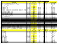
Box 1-PN <strong>55089</strong>-1<br />
<strong>Part</strong> # Description Qty Illus.<br />
90-1110 Bump Stop Spacer 4 2,7<br />
90-2041 Sway Bar Link 2 1<br />
13-90061 U-Bolt, 1/<strong>2”</strong> x 3-1/4” x 8” 2 2<br />
13-90074 U-Bolt, 1/<strong>2”</strong> x 2-1/<strong>2”</strong> x 7 1/<strong>2”</strong> 2 2<br />
90-6025 Hardware Pack Containing:<br />
70-0503501500 1/<strong>2”</strong> x 3 1/<strong>2”</strong> USS Gr. 5 Hex Bolt 7 5,8<br />
71-1207017508800 12mm x 1.75 x 70mm Hex Bolt 1 3<br />
71-1205017508800 12mm x 1.75 x 50mm Hex Bolt 1 3<br />
70-0371001500 3/8” x 1” USS Gr. 5 Hex Bolt 1 6<br />
70-031101500 5/16” x 1” USS Gr. 5 Hex Bolt 1 8<br />
70-0251001500 1/4” x 1” USS Gr. 5 Hex Bolt 2 4<br />
73-05000036 1/<strong>2”</strong> Split Lock Washer 6 5<br />
73-05000030 1/<strong>2”</strong> SAE Flat Washer 11 2,3,5,7,8<br />
73-03700030 3/8” SAE Flat Washer 2 6<br />
73-03100030 5/16” SAE Flat Washer 2 8<br />
73-02500030 1/4” SAE Flat Washer 4 4<br />
72-05000100512 1/<strong>2”</strong> USS Nylock Nut 2 8<br />
72-03700100512 3/8” USS Nylock Nut 1 6<br />
72-01217508812 12mm x 1.75 Nylock Nut 1 3<br />
72-03100100512 5/16” USS Nylock Nut 1 8<br />
72-02500100512 1/4” USS Nylock Nut 2 4<br />
20-65991 1/<strong>2”</strong> Hi Nut Pack 1 2<br />
90-6026 Bushing Pack Containing:<br />
15-11096 YJ Spring Eye Bushing 16 1A<br />
45359 5/8” Rubber Hourglass Bushing 4 1<br />
<strong>55089</strong>-1 Spring Eye Sleeve YJ 1/<strong>2”</strong> I.D. 4 1A<br />
<strong>55089</strong>-2 Spring Eye Sleeve YJ 9/16” I.D. 4 1A<br />
90-6027 Hardware Pack Containing:<br />
90-2002 Transfer Case Conicial Spacer 6 5<br />
90-2048 Transfer Case Spacer 6 5<br />
90-2049 Sleeve Rear Trac Bar 1 8<br />
90-6028 Bracket <strong>Part</strong>s Pack Containing:<br />
90-1111 Front Trac Bracket 1<br />
90-1112 Square Washer - Large Hole 1<br />
90-1113 Square Washer - Small Hole 1<br />
<strong>55089</strong>-3 Front Brakeline Extension (Drvr.) 1<br />
<strong>55089</strong>-4 Front Brakeline Extension (Pass.) 1<br />
<strong>55089</strong>-5 Rear Brakeline Extension 1<br />
90-1107 Rear Trac Bracket 1<br />
99-250 2.5 Degree Axle Shim 2 7<br />
90-6029 Hardware Pack Brakeline<br />
15-10966 3/8” Hose Clamp 4<br />
13-20447 #10 x 1/<strong>2”</strong> HWH Screw 4<br />
90-6056 Hardware Pack Containing:<br />
73-05000030 1/<strong>2”</strong> SAE Flat Washer 16<br />
2<br />
<strong>55089</strong><br />
Created<br />
12.5.05
<strong>55089</strong><br />
Created<br />
12.5.05<br />
Following parts are used in conjunction with this kit and must be purchased separately.<br />
2.5 inch lift kit:<br />
51313 Front Spring-4 Leaf (2-1/<strong>2”</strong> Lift) 2 1A<br />
51323 Rear Spring-4 Leaf (2-1/<strong>2”</strong> Lift) 2 1A<br />
Rear U-Bolts - 50070<br />
SHOCKS:<br />
2.5 Suspension - 326510 Front<br />
2.5 Suspension - 322500 Rear<br />
4.0 inch lift kit:<br />
51413 Front Spring-5 Leaf (4” Lift) 2 1A<br />
51423 Rear Spring-4 Leaf (4” Lift) 2 1A<br />
Brakeline - 7425<br />
Rear U-Bolts - 50070<br />
SHOCKS:<br />
4.0 Suspension - 329510 Front<br />
4.0 Suspension - 324509 Rear<br />
Optional parts MAY be purchased separately,<br />
Brakeline - 7425<br />
Steering Stabilizer - 219200<br />
Tail Shaft Conversion - 4007 - See catalog for driveshaft application<br />
PLEASE NOTE WITH 4” SUSPENSION:<br />
Tire and wheel choice is crucial in assuring proper fit performance and the safety of your<br />
<strong>Pro</strong> <strong>Comp</strong> equipped vehicle. For this application a wheel not to exceed 8” in width with a<br />
maximum backspacing of 3.5” must be used. Diameter of wheel may be any of the following<br />
2 choices, 15”, 16”. Any other diameter, either smaller or larger, will not be endorsed<br />
as acceptable by <strong>Pro</strong> <strong>Comp</strong> Suspension and will void any and all warranties, written or<br />
implied. In addition, a quality tire of radial design, not to exceed 33” tall x 12.50” wide is<br />
recommended.<br />
PLEASE NOTE WITH 2 1/<strong>2”</strong> SUSPENSION:<br />
Tire and wheel choice is crucial in assuring proper fit performance and the safety of your<br />
<strong>Pro</strong> <strong>Comp</strong> equipped vehicle. For this application a wheel not to exceed 8” in width with a<br />
maximum backspacing of 3.5 must be used. Diameter of wheel may be any of the following<br />
2 choices, 15”, 16”. Any other diameter, either smaller or larger, will not be endorsed<br />
as acceptable by <strong>Pro</strong> <strong>Comp</strong> Suspension and will void any and all warranties, written or<br />
implied. In addition, a quality tire of radial design, not to exceed 31” tall x 10.5” wide is<br />
recommended.<br />
3
♦<br />
♦<br />
♦<br />
♦<br />
♦<br />
♦<br />
♦<br />
♦<br />
♦<br />
♦<br />
♦<br />
Introduction:<br />
This installation requires a professional mechanic!<br />
<strong>55089</strong><br />
Created<br />
12.5.05<br />
We recommend that you have access to a factory service manual for your vehicle to assist<br />
in the disassembly and reassembly of your vehicle. It contains a wealth of detailed information.<br />
Prior to installation, carefully inspect the vehicle’s steering and driveline systems paying<br />
close attention to the tie rod ends, ball joints, wheel bearing preload, pitman and idler arm.<br />
Additionally, check steering-to-frame and suspension-to-frame attaching points for stress<br />
cracks. The overall vehicle must be in excellent working condition. Repair or replace all<br />
worn or damaged parts!<br />
Read the instructions carefully and study the illustrations before attempting installation!<br />
You may save yourself a lot of extra work.<br />
Check the parts and hardware against the parts list to assure that your kit is complete.<br />
Separating parts according to the areas where they will be used and placing the hardware<br />
with the brackets before you begin will save installation time.<br />
Check the special equipment list and ensure the availability of these tools.<br />
Secure and properly block vehicle prior to beginning installation.<br />
ALWAYS wear safety glasses when using power tools or working under the vehicle!<br />
Use caution when cutting is required under the vehicle. The factory undercoating is flammable.<br />
Take appropriate precautions. Have a fire extinguisher close at hand.<br />
Foot pound torque readings are listed on the Torque Specifications chart at the end of the<br />
instructions. These are to be used unless specifically directed otherwise. Apply thread lock<br />
retaining compound where specified.<br />
Please note that while every effort is made to ensure that the installation of your <strong>Pro</strong><br />
<strong>Comp</strong> lift kit is a positive experience, variations in construction and assembly in the<br />
vehicle manufacturing process will virtually ensure that some parts may seem difficult<br />
to install. Additionally, the current trend in manufacturing of vehicles results in<br />
a frame that is highly flexible and may shift slightly on disassembly prior to installation.<br />
The use of pry bars and tapered punches for alignment is considered normal<br />
and usually does not indicate a faulty product. However, if you are uncertain about<br />
some aspect of the installation process, please feel free to call our tech support department<br />
at the number listed on the cover page. We do not recommend that you<br />
modify the <strong>Pro</strong> <strong>Comp</strong> parts in any way as this will void any warranty expressed or<br />
implied by the <strong>Pro</strong> <strong>Comp</strong> Suspension company.<br />
4
Installation Instructions:<br />
<strong>55089</strong><br />
Created<br />
12.5.05<br />
FRONT:<br />
1) Secure and properly block the vehicle. Place the floor jack under the axle and then raise vehicle.<br />
Place the jack stands under the frame, behind the front springs.<br />
2) Remove the sway bar upper and lower mount pins, shocks, wheels and tires. Remove the<br />
bolts attaching the front brake lines to the top of the frame. Using the same mount pins, replace the<br />
stock sway bar link pins with the new link pins (90-2041) and the hour glass bushings (15-11083) as<br />
shown in ILLUSTRATION 1.<br />
3) Supporting the front axle, remove the front trac bar bolt at the axle. Relieve the front springs<br />
by lowering the floor jack at this time.<br />
4) Remove the front U-bolts and the supporting front axle, remove the spring hanger and shackle<br />
bolts and save them<br />
for re-installation later<br />
5) Install bushings and sleeves into the spring eyes. Be sure to install one 1/<strong>2”</strong> ID sleeve and one<br />
9/16” ID sleeve per<br />
spring.<br />
6) Install the front springs with 1/<strong>2”</strong> ID sleeves into the spring shackle, as shown in ILLUSTRA-<br />
ILLUSTRATION 1<br />
ILLUSTRATION 1A<br />
VEHICLE FRAME<br />
STABILIZER<br />
SHAFT<br />
SWAY BAR LINK<br />
PIN (90-2041)<br />
UPPER<br />
MOUNT<br />
PIN<br />
LEAF SPRING<br />
SPRING EYE<br />
BUSHING<br />
15-11096<br />
IMP<strong>OR</strong>TANT NOTE:<br />
INSTALL 1/<strong>2”</strong> SAE FLAT<br />
WASHER INSIDE<br />
STOCK SHACKLE<br />
PLATES WHEN USING<br />
REPLACEMENT URE-<br />
THANE BUSHINGS IN<br />
FRAME. USE WASHERS<br />
ON PRO COMP SPRING<br />
END WITH STOCK<br />
SHACKLES<br />
LOWER MOUNT PIN<br />
LEAF SPRING<br />
INSTALL ONE END OF SPRING WITH 1/<strong>2”</strong> ID SLEEVE AND<br />
THE OTHER END WITH A 9/16” ID SLEEVE<br />
5
TION 1A.<br />
7) Lower the axle onto the springs, placing<br />
the front bumpstops (90-1110) over the axle tube.<br />
Install the new, longer U-bolts over one side of the<br />
bumpstops and place the larger I.D. U-bolts over<br />
the axle tube castings (see ILLUSTRATION 2).<br />
Re-install the spring retainer plate using 1/<strong>2”</strong> flat<br />
washers and 1/<strong>2”</strong> fine high nuts. Tighten U-bolts<br />
to 90 ft./lbs.<br />
FRONT TRAC BAR MODIFICATION:<br />
ILLUSTRATION 2<br />
BUMPSTOP, (90-1110)<br />
TRAC MOUNT<br />
LEAF SPRING<br />
<strong>55089</strong><br />
Created<br />
12.5.05<br />
U-BOLT, 2 1/<strong>2”</strong> X 7 1/<strong>2”</strong><br />
AXLE<br />
FRONT<br />
WHEEL<br />
SIDE<br />
8) Referring to ILLUSTRATION 3, install the<br />
large hole square washer (90-1112) over the trac<br />
bar mount on the axle. Place the front trac bar extension<br />
bracket (90-1111) on the same mount with<br />
the slotted hole at the top of the bracket. Place the<br />
12mm x 70mm bolt and 1/<strong>2”</strong> flat washer through<br />
FLAT<br />
WASHER,<br />
1/<strong>2”</strong><br />
HIGH NUT, 1/<strong>2”</strong> FINE<br />
SPRING RETAINER<br />
PLATE<br />
the small hole square washer (90-1113) and into the assembly on the axle. Install the 1/<strong>2”</strong> washer and<br />
12mm nut on the backside and tighten the assembly to 80 ft./lbs. Allow the trac bar to hang freely until<br />
the vehicle is sitting on the ground.<br />
9) Install the two front brake bracket extensions (<strong>55089</strong>-3/Drvr.) and (<strong>55089</strong>-4/Pass.) where the<br />
brake lines were mounted to the frame using the existing bolts. Use the 1/4” x 1” hex bolts, washer<br />
and nuts to attach the original brake line brackets to the bracket extensions on the other end. Refer to<br />
ILLUSTRATION 4.<br />
10) Install the shocks, wheels and tires.<br />
Use the 3/8” pal nuts on the upper shock<br />
mounts.<br />
11) Lower the vehicle to the ground,<br />
tighten all spring mount bolts and re-install the<br />
sway bar lower mount pins. Tighten all fasteners<br />
to required torque specifications (see listing<br />
on last page of instruction sheet).<br />
12) Referring again to ILLUSTRATION 3,<br />
install the 12mm x 50mm bolt and the 1/<strong>2”</strong><br />
washer through the trac bar and into the new<br />
bracket on the axle. Tighten to 75 ft./lbs.<br />
TRANSFER CASE MODIFICA-<br />
TION:<br />
HEX BOLT,<br />
12mm x 70mm<br />
HEX BOLT, 12mm x 50mm<br />
FLAT<br />
WASHER, 1/<strong>2”</strong><br />
SQUARE WASHER<br />
(SMALL HOLE)<br />
90-1113<br />
FLAT<br />
WASHER, 1/<strong>2”</strong><br />
TRAC-BAR<br />
EXTENSION<br />
(90-1111)<br />
ILLUSTRATION 3<br />
FLAT<br />
WASHER, 1/<strong>2”</strong><br />
NYLOC<br />
NUT,<br />
12mm<br />
EXISTING<br />
FRONT<br />
TRAC-BAR<br />
MOUNT<br />
SQUARE WASHER<br />
(LARGE HOLE)<br />
90-1112<br />
6
<strong>55089</strong><br />
Created<br />
12.5.05<br />
13) Place the floor jack under the transfer case<br />
skid plate. Loosen the three adjustment mount<br />
bolts on the bottom side of the skid plate.<br />
14) Remove the skid plate from the frame<br />
bolts (three on each side). Lower the assembly<br />
enough to place the transfer case spacer tubes (90-<br />
2048) between the skid plate and the frame. Use<br />
the 1/<strong>2”</strong> x 3-1/<strong>2”</strong> hex bolts, with the hardware<br />
provided, to re-install the skid plate, as shown in<br />
ILLUSTRATION 5.<br />
REAR:<br />
1) Block the front wheels, place the floor jack<br />
under the rear axle and raise the vehicle. Place the<br />
jack stands under the frame on each side in front<br />
of the spring hanger. Remove the shocks, wheels<br />
and tires.<br />
ILLUSTRATION 4<br />
EXISTING<br />
DRIVER SIDE<br />
SHOWN<br />
BRAKELINE<br />
FRONT BRAKE<br />
BRACKET<br />
<strong>55089</strong>-3 (DRVR.)<br />
<strong>55089</strong>-4 (PASS.)<br />
HEX BOLT,<br />
1/4” x 1”<br />
FLAT WASHER,<br />
1/4”<br />
NYLOC NUT, 1/4”-20<br />
2) Remove the brake hose clip attaching the hose to the upper frame bracket. Remove the hose<br />
assembly from the bracket and install the rear brake bracket extension (<strong>55089</strong>-5) using the 3/8” bolt<br />
and washer in the frame bracket hole. See ILLUSTRATION 6. Re-align the brake line. Install it into<br />
the new bracket, attaching it to the existing clip. Tighten the 3/8” bolt to 20 ft./lbs.<br />
3) Keeping slight pressure on the axle, remove the trac bar at the axle, axle u-bolts and spring.<br />
Refer back to steps 5 and 6, ILLUSTRATION 1 and 1A, for installation of the spring bushings and<br />
sleeves on the front installation. Follow these same instructions for the rear.<br />
4) Place aluminum shims between the axle and the spring with the thick end of the shim toward<br />
the front of the vehicle and over spring bolts as shown in ILLUSTRATION 7. Lower the axle on to the<br />
shims and springs. Place the bump-stops on top of the axle tube and under the existing outer u-bolts.<br />
ILLUSTRATION 5<br />
FRAME<br />
TRANSFER CASE<br />
SPACER TUBE<br />
90-2048<br />
SKIDPLATE<br />
FLAT WASHER, 1/<strong>2”</strong><br />
CONICAL SPACER<br />
90-2002<br />
LOCK<br />
WASHER, 1/<strong>2”</strong><br />
HEX BOLT, 1/<strong>2”</strong><br />
X 3 1/<strong>2”</strong> LG.<br />
7
Re-install the u-bolt plates and existing nuts and<br />
tighten to the required torque specifications. (See<br />
listing on the last page of the instruction sheet).<br />
5) Install the rear trac bar extension bracket<br />
(90-1107) into the bracket on the axle with the slotted<br />
holes at the top. Install the 5/16” bolt, washer<br />
and nut into the small holes towards the outside of<br />
the vehicle. Refer to ILLUSTRATION 8. Tighten<br />
the bracket into place. Allow the trac bar to hang<br />
freely until the vehicle is sitting on the ground.<br />
6) Referring again to ILLUSTRATION 8, place<br />
the rear trac bar sleeve (90-2049) inside the rear trac<br />
bar extension bracket, lining it up with the slotted<br />
holes. Install with 1/<strong>2”</strong> x 3-1/<strong>2”</strong> bolt, two 1/<strong>2”</strong> flat<br />
washers and the 1/<strong>2”</strong> nut, as shown. Tighten to 75<br />
ft./lbs.<br />
7) Install the shocks, wheels and tires.<br />
ILLUSTRATION 6<br />
FLAT WASHER,<br />
3/8”<br />
FRAME<br />
FLAT WASHER,<br />
3/8”<br />
NYLOC NUT,<br />
3/8”-16<br />
<strong>55089</strong><br />
Created<br />
12.5.05<br />
HEX<br />
BOLT,<br />
3/8”-1”<br />
REAR<br />
BRAKE<br />
BRACKET<br />
<strong>55089</strong>-5<br />
CAUTION: Emergency cables may appear to be too tight on some models. Simply bend<br />
the bracket attaching the cables to the floor downward 90 degrees. This will allow the cables to<br />
move.<br />
8) Lower the vehicle to the ground and install the existing bolt and washer through the upper slotted<br />
hole and through the trac bar. Install the existing nut. Tighten all fasteners to the required torque<br />
specifications for the spring shackles and hangers (see listing on the last page of the instruction sheet).<br />
ADDITIONAL NOTES:<br />
⇒ The weld at the trac bar may need to be<br />
ground to allow shock clearance.<br />
⇒ Have the front end checked and aligned.<br />
⇒ Check the shifters for proper engagement.<br />
The floor may require trimming or notching<br />
to allow full travel and engagement of<br />
the shifter.<br />
ILLUSTRATION 7<br />
EXISTING<br />
U-BOLTS<br />
REAR AXLE<br />
SHIM, 2.5<br />
99-250<br />
BUMPSTOP<br />
(90-1110)<br />
LEAF SPRING<br />
8<br />
FLAT<br />
WASHER,<br />
1/<strong>2”</strong><br />
HIGH NUT, 1/<strong>2”</strong> FINE<br />
SPRING<br />
RETAINER<br />
PLATE
<strong>55089</strong><br />
Created<br />
12.5.05<br />
ILLUSTRATION 8<br />
EXISTING<br />
TRAC BAR<br />
REAR TRAC-BAR EXTENSION<br />
BRACKET, (90-1107)<br />
EXISTING NUT<br />
FLAT WASHER, 5/16”<br />
SLEEVE REAR<br />
TRAC-BAR 90-2049<br />
NYLOC<br />
NUT,<br />
5/16”-18<br />
FLAT WASHER, 1/<strong>2”</strong><br />
NYLOC NUT, 1/<strong>2”</strong>-13<br />
FLAT<br />
WASHER, 1/<strong>2”</strong><br />
AXLE<br />
HEX BOLT,<br />
1/<strong>2”</strong> X 3 1/<strong>2”</strong><br />
HEX BOLT, 5/16” X 1”<br />
FLAT WASHER, 5/16”<br />
T<strong>OR</strong>QUE SPECIFICATIONS:<br />
Spring to shackle bolts, front and rear.............................. Tighten until shackle side plates contact<br />
bushings. Do not over tighten.<br />
Spring to frame hanger bolts, front and rear.....................105 ft./lbs.<br />
Existing u-bolts, rear.......................................................72-97 ft./lbs.<br />
Front trac bar bracket to axle..........................................74 ft./lbs.<br />
Rear trac bar bracket to axle, models 35 and 44...............125 ft./lbs<br />
Rear trac bar to bracket...................................................100 ft./lbs.<br />
Front trac bar to bracket assembly...................................75 ft./lbs.<br />
Front upper shock mount..................................................9 ft./lbs.<br />
All lower shock mounts....................................................45 ft./lbs.<br />
Rear upper shock mount...................................................45 ft./lbs.<br />
Transfer case skid plate mount bolts................................75 ft./lbs.<br />
1/4”.................................................................................8 ft./lbs.<br />
5/16”...............................................................................17 ft./lbs.<br />
3/8”................................................................................30 ft./lbs.<br />
1/<strong>2”</strong>................................................................................75 ft./lbs.<br />
12mm.............................................................................80 ft./lbs.<br />
1/<strong>2”</strong> u-bolts.....................................................................90 ft./lbs.<br />
9
Notice to Owner operator, Dealer and Installer:<br />
Vehicles that have been enhanced for off-road performance often have unique handling characteristics due to the<br />
higher center of gravity and larger tires. This vehicle may handle, react and stop differently than many passenger cars or<br />
unmodified vehicles, both on and off–road. You must drive your vehicle safely! Extreme care should always be taken to<br />
prevent vehicle rollover or loss of control, which can result in serious injury or even death. Always avoid sudden sharp turns<br />
or abrupt maneuvers and allow more time and distance for braking! <strong>Pro</strong> <strong>Comp</strong> reminds you to fasten your seat belts at all<br />
times and reduce speed! We will gladly answer any questions concerning the design, function, maintenance and correct use<br />
of our products.<br />
Please make sure your Dealer/Installer explains and delivers all warning notices, warranty forms and<br />
instruction sheets included with <strong>Pro</strong> <strong>Comp</strong> product.<br />
Application listings in this catalog have been carefully fit checked for each model and year denoted. However, <strong>Pro</strong><br />
<strong>Comp</strong> reserves the right to update as necessary, without notice, and will not be held responsible for misprints, changes or<br />
variations made by vehicle manufacturers. Please call when in question regarding new model year, vehicles not listed by<br />
specific body or chassis styles or vehicles not originally distributed in the USA.<br />
Please note that certain mechanical aspects of any suspension lift product may accelerate ordinary<br />
wear of original equipment components. Further, installation of certain <strong>Pro</strong> <strong>Comp</strong> products may void the vehicle’s<br />
factory warranty as it pertains to certain covered parts; it is the consumer’s responsibility to check with their local dealer for<br />
warranty coverage before installation of the lift.<br />
Warranty and Return policy:<br />
<strong>Pro</strong> <strong>Comp</strong> warranties its full line of products to be free from defects in workmanship and materials. <strong>Pro</strong> <strong>Comp</strong>’s obligation<br />
under this warranty is limited to repair or replacement, at <strong>Pro</strong> <strong>Comp</strong>’s option, of the defective product. Any and all<br />
costs of removal, installation, freight or incidental or consequential damages are expressly excluded from this warranty. <strong>Pro</strong><br />
<strong>Comp</strong> is not responsible for damages and / or warranty of other vehicle parts related or non-related to the installation of <strong>Pro</strong><br />
<strong>Comp</strong> product. A consumer who makes the decision to modify his vehicle with aftermarket components of any kind will<br />
assume all risk and responsibility for potential damages incurred as a result of their chosen modifications. Warranty coverage<br />
does not include consumer opinions regarding ride comfort, fitment and design. Warranty claims can be made directly<br />
with <strong>Pro</strong> <strong>Comp</strong> or at any factory authorized <strong>Pro</strong> <strong>Comp</strong> dealer.<br />
IMP<strong>OR</strong>TANT! To validate the warranty on this purchase please be sure to mail in the warranty card.<br />
Claims not covered under warranty-<br />
• <strong>Part</strong>s subject to normal wear, this includes bushings, bump stops, ball joints, tie rod ends and heim joints<br />
• Discontinued products at <strong>Pro</strong> <strong>Comp</strong>’s discretion<br />
• Bent or dented product<br />
• Finish after 90 days<br />
• Leaf or coil springs used without proper bump stops<br />
• Light bulbs<br />
• <strong>Pro</strong>ducts with evident damage caused by abrasion or contact with other items<br />
• Damage caused as a result of not following recommendations or requirements called out in the<br />
installation manuals<br />
• <strong>Pro</strong>ducts used in applications other than listed in <strong>Pro</strong> <strong>Comp</strong>’s catalog<br />
• <strong>Comp</strong>onents or accessories used in conjunction with other manufacturer’s systems<br />
• Tire & Wheel Warranty as per <strong>Pro</strong> <strong>Comp</strong>etition Tire <strong>Comp</strong>any policy<br />
• Warranty claims without “<strong>Pro</strong>of of Purchase”<br />
• <strong>Pro</strong> <strong>Comp</strong> <strong>Pro</strong> Runner coil over shocks are considered a serviceable shock with a one-year<br />
warranty against leakage only. Rebuild service and replacement parts will be available and sold<br />
separately by <strong>Pro</strong> <strong>Comp</strong>. Contact <strong>Pro</strong> <strong>Comp</strong> for specific service charges.<br />
• <strong>Pro</strong> <strong>Comp</strong> accepts no responsibility for any altered product, improper installation, lack of or<br />
improper maintenance, or improper use of our products.<br />
E-Mail: tech@explorerprocomp.com<br />
Website: www.explorerprocomp.com<br />
Fax: (619) 216-1474<br />
Ph: (619) 216-1444<br />
PLACE<br />
WARRANTY REGISTRATION<br />
NUMBER<br />
HERE: __________________