CHAPTER ONE STRESS, STRAIN, ENERGY and FAILURE
CHAPTER ONE STRESS, STRAIN, ENERGY and FAILURE
CHAPTER ONE STRESS, STRAIN, ENERGY and FAILURE

You also want an ePaper? Increase the reach of your titles
YUMPU automatically turns print PDFs into web optimized ePapers that Google loves.
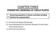
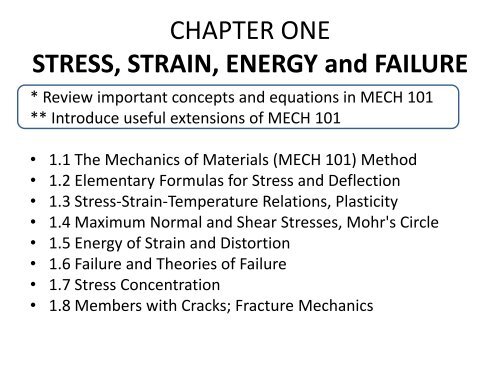
<strong>CHAPTER</strong> <strong>ONE</strong><br />
<strong>STRESS</strong>, <strong>STRAIN</strong>, <strong>ENERGY</strong> <strong>and</strong> <strong>FAILURE</strong><br />
* Review important concepts <strong>and</strong> equations in MECH 101<br />
** Introduce useful extensions of MECH 101<br />
• 1.1 The Mechanics of Materials (MECH 101) Method<br />
• 1.2 Elementary Formulas for Stress <strong>and</strong> Deflection<br />
• 1.3 Stress-Strain-Temperature Relations, Plasticity<br />
• 1.4 Maximum Normal <strong>and</strong> Shear Stresses, Mohr's Circle<br />
• 1.5 Energy of Strain <strong>and</strong> Distortion<br />
• 1.6 Failure <strong>and</strong> Theories of Failure<br />
• 1.7 Stress Concentration<br />
• 1.8 Members with Cracks; Fracture Mechanics
Review <strong>and</strong> Summary<br />
1.1 THE MECHANICS OF MATERIAL(MECH 101) METHOD<br />
• Structure
Review <strong>and</strong> Summary<br />
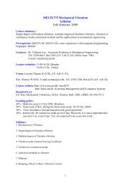
1.2 ELEMENTARY FORMULAS FOR <strong>STRESS</strong> AND DEFLECTION IN MECH 101
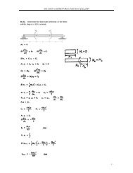
The method of derivation of formula in MECH 101<br />
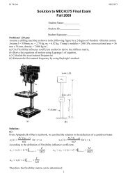
(a) (b) (c)<br />
FIGURE 1.1.2. Brief summary of how the flexure formula σ = My/I is derived. (a) Plane sections remain plane after loading.<br />
(b) Linear variation of axial normal strain e <strong>and</strong> a linear stress-strain relation. (c) Axial normal stress distribution <strong>and</strong> the<br />
pertinent equilibrium equations.<br />
(1) Establish the geometry of deformation by experiments<br />
(2) Determine the strain distribution by the analysis of the geometry of deformation<br />
(3) Determine the stress distribution from the strain distribution by using the Hook's law<br />
(4) Relates stress to load by equilibrium (free body diagram)<br />
• Principal of superposition<br />
• Concept of safety factor
Review <strong>and</strong> Summary<br />
1.3 <strong>STRESS</strong>-<strong>STRAIN</strong>-TEMPERATURE RELATIONS, PLASTICITY
• Plain stress state
Review <strong>and</strong> Summary<br />
1.4 MAXIMUM NORMAL AND SHEAR <strong>STRESS</strong>ES, MOHR'S CIRCLE<br />
(a)<br />
(b)<br />
(c)<br />
(d)
Review <strong>and</strong> Summary<br />
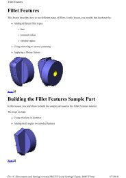
1.5 <strong>ENERGY</strong> OF <strong>STRAIN</strong> AND DISTORTION<br />
• Strain energy density – the work done per unit volume during<br />
stressing an elastic body<br />
(a)<br />
FIGURE 1.6.1. Unit volumes of linearly elastic material, with distorted shapes shown by<br />
dashed lines. (a) Uniaxial stress σ. (b) Shear stress τ.<br />
(b)
• The total strain energy in a body of volume V is<br />
(1) straight bar under axial load P at each end<br />
(2) straight circular shaft of constant cross section under torque T applied at each end<br />
(3) straight beam of constant cross section under moment M applied at each end
Review <strong>and</strong> Summary<br />
1.6 <strong>FAILURE</strong> AND THEORIES OF <strong>FAILURE</strong><br />
• Two major forms of failure:<br />
(1) failure due to brittle fracture, brittle materials<br />
(2) failure due to yielding, ductile materials
Review <strong>and</strong> Summary<br />
1.7 <strong>STRESS</strong> CONCENTRATION
Figure 1.8.2. Selected stress concentration factors K t for plane <strong>and</strong> cylindrical geometries, from<br />
[1.8]. Maximum stresses computed from these K t factors are at the edges of holes or notches<br />
(see sketches on page 28).
Review <strong>and</strong> Summary<br />
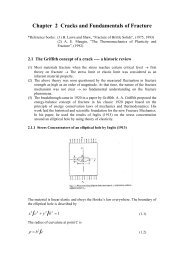
1.8 MEMBERS WITH CRACKS; FRACTURE MECHANICS<br />
• Stress distribution when there is a crack<br />
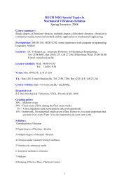
(a) (b) (c)<br />
FIGURE 1.9.1. (a) Flat sheet of thickness t in uniaxial plane stress, with a sharp internal<br />
crack of length 2a. (b) Qualitative depiction of how normal stresses are distributed near a<br />
crack tip. (c) Influence of specimen thickness on fracture toughness.
• Stress intensity factor<br />
• Critical stress intensity factor K IC fracture toughness (material<br />
constant like strength)<br />
critical condition for fracture: KI = K IC<br />
If stress σ <strong>and</strong> K IC are given, the maximum crack length (a c ) can<br />
be determined by KI = K IC