Venturi Replacement Kit PSRKIT80 thru 83 - Triangle Tube
Venturi Replacement Kit PSRKIT80 thru 83 - Triangle Tube
Venturi Replacement Kit PSRKIT80 thru 83 - Triangle Tube

Create successful ePaper yourself
Turn your PDF publications into a flip-book with our unique Google optimized e-Paper software.
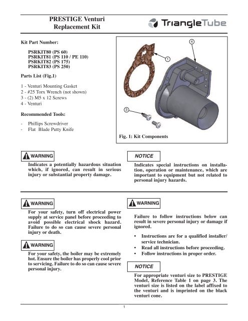
PRESTIGE <strong>Venturi</strong><br />
<strong>Replacement</strong> <strong>Kit</strong><br />
<strong>Kit</strong> Part Number:<br />
4<br />
<strong>PSRKIT80</strong> (PS 60)<br />
PSRKIT81 (PS 110 / PE 110)<br />
PSRKIT82 (PS 175)<br />
PSRKIT<strong>83</strong> (PS 250)<br />
1<br />
Parts List (Fig.1)<br />
1 - <strong>Venturi</strong> Mounting Gasket<br />
2 - #25 Torx Wrench (not shown)<br />
3 - (2) M5 x 12 Screws<br />
4 - <strong>Venturi</strong><br />
Recommended Tools:<br />
- Phillips Screwdriver<br />
- Flat Blade Putty Knife<br />
3<br />
Fig. 1: <strong>Kit</strong> Components<br />
WARNING<br />
Indicates a potentially hazardous situation<br />
which, if ignored, can result in serious<br />
injury or substantial property damage.<br />
NOTICE<br />
Indicates special instructions on installation,<br />
operation or maintenance, which are<br />
important to equipment but not related to<br />
personal injury hazards.<br />
WARNING<br />
For your safety, turn off electrical power<br />
supply at service panel before proceeding to<br />
avoid possible electrical shock hazard.<br />
Failure to do so can cause severe personal<br />
injury or death.<br />
WARNING<br />
For your safety, the boiler may be extremely<br />
hot. Ensure the boiler has properly cool prior<br />
to servicing. Failure to do so can cause severe<br />
personal injury.<br />
WARNING<br />
Failure to follow instructions below can<br />
result in severe personal injury or damage if<br />
ignored.<br />
• Instructions are for a qualified installer/<br />
service technician.<br />
• Read all instructions before proceeding.<br />
• Follow instructions in proper order.<br />
NOTICE<br />
For appropriate venturi size to PRESTIGE<br />
Model, Reference Table 1 on page 3. The<br />
venturi size is listed on the label affixed to<br />
the venturi and is imprinted on the black<br />
venturi cone.<br />
1
PRESTIGE <strong>Venturi</strong><br />
<strong>Replacement</strong> <strong>Kit</strong><br />
Instructions<br />
1. Turn power to the unit “OFF”.<br />
2. Remove the front jacket panel. Swing away the<br />
Control Module panel (MCBA) or tilt down the<br />
Control Module panel (TriMax).<br />
3. Shut off gas supply to the Prestige boiler at the<br />
main manual shutoff valve.<br />
4. Disconnect the gas piping at the brass union<br />
located near the gas valve inside the boiler<br />
enclosure.<br />
5. Using a Phillips screwdriver disconnect the rectifier<br />
cable to the gas valve (MCBA).<br />
<strong>Venturi</strong><br />
Mounting Screw<br />
8. Using the #25 Torx wrench from the kit remove<br />
the 2 venturi mounting screws attaching the<br />
venturi / gas valve assembly to the blower, see<br />
Fig. 2. Remove the venturi / gas valve assembly<br />
from the blower.<br />
NOTICE<br />
There is a gasket between the venturi and the<br />
blower housing. If the gasket “sticks” to the<br />
blower housing use a flat blade putty knife to<br />
remove any gasket material. Make sure not<br />
to scratch or score the mating surface on the<br />
blower housing.<br />
9. Remove the three screws attaching the gas valve<br />
to the venturi as shown in Fig. 3. Use Torx<br />
wrench supplied in kit to remove screws. Note<br />
orientation of the venturi to the old gas valve for<br />
reassembly of the new venturi on the gas valve.<br />
10. Reassemble the gas valve, using the existing three<br />
Torx screws to the venturi. See Fig. 3.<br />
WARNING<br />
6. Remove Molex plug from gas valve (TriMax).<br />
7. Remove the air inlet elbow from the venturi.<br />
NOTICE<br />
<strong>Venturi</strong><br />
Mounting Screw<br />
Fig. 2: <strong>Venturi</strong>/Gas Valve Assembly<br />
<strong>Venturi</strong>/Gas<br />
Valve Assembly<br />
Note the orientation of the venturi / gas valve<br />
assembly and the venturi gasket in relation<br />
to the blower housing when disassembling<br />
the venturi / gas valve assembly.<br />
Ensure the gas valve/orifice gasket is in place<br />
before reassembling the gas valve and venturi.<br />
Failure to do so can result in death, serious<br />
injury or substantial property damage.<br />
NOTICE<br />
For propane installations a brass orifice is<br />
located inside the gas valve/orifice gasket.<br />
This orifice must be placed inside of the new<br />
gas valve/orifice gasket before reassembly.<br />
WARNING<br />
Failure to insert the propane brass orifice, on<br />
propane installations, before reassembling<br />
the gas valve and venturi can result in the<br />
production of carbon monoxide due to<br />
incomplete combustion and may result in<br />
death, serious injury or substantial property<br />
damage.<br />
2
PRESTIGE <strong>Venturi</strong><br />
<strong>Replacement</strong> <strong>Kit</strong><br />
NOTICE<br />
For the reassembly process do not use adhesive<br />
on any gasket surface.<br />
11. Install the venturi gasket on the venturi and<br />
reassemble the venturi / gas valve assembly to<br />
the blower housing using the (2) M5 x 12<br />
mounting screws supplied in the kit. Use the<br />
#25 Torx wrench to tighten all screws and<br />
secure the assembly.<br />
Blower<br />
<strong>Venturi</strong> / Blower Gasket<br />
Table 1: <strong>Venturi</strong> Sizes<br />
PRESTIGE<br />
Model<br />
<strong>Venturi</strong><br />
Size<br />
PS 60 055<br />
PS 110<br />
PE 110<br />
002<br />
PS 175 052<br />
PS 250 051<br />
12. Reconnect the rectifier plug to the gas valve<br />
using the Phillips head screw (MCBA).<br />
13. Reconnect Molex plug to the gas valve<br />
(TriMax).<br />
14. Reconnect the brass gas piping union connection.<br />
Open the main manual gas shutoff valve<br />
before placing the PRESTIGE unit back into<br />
operation check and test all gas connections for<br />
leaks. Repair leaks if found.<br />
WARNING<br />
Do not check for gas leaks with an open flame.<br />
Use a bubble test. Failure to check for gas<br />
leaks can cause severe personal injury, death<br />
or substantial property damage.<br />
<strong>Venturi</strong><br />
Fig. 3: <strong>Venturi</strong> Assembly<br />
17. Turn the electrical power “ON” to the PRES-<br />
TIGE to return the unit back into service.<br />
COMBUSTION TEST/ADJUSTEMENT<br />
Gas Valve<br />
It is recommended that the installer perform a complete<br />
combustion check to ensure the following<br />
combustion levels are met at high and low inputs<br />
and the burner is operating at optimum conditions.<br />
Table 2: Recommended Combustion Levels<br />
Natural Gas<br />
Propane<br />
O2 Min. 2.30% 2.70%<br />
O2 Max. 5.30% 4.70%<br />
CO2 Min. 8.80% 10.70%<br />
CO2 Max. 10.50% 12.00%<br />
CO Max. 100 ppm 100 ppm<br />
15. Reattach the air inlet elbow to the venturi.<br />
16. Reposition the Control Module panel and reattach<br />
the front jacket panel.<br />
3
PRESTIGE <strong>Venturi</strong><br />
<strong>Replacement</strong> <strong>Kit</strong><br />
WARNING<br />
The combustion testing and adjustments<br />
must be performed by a qualified installer,<br />
service agency or the gas supplier. All combustion<br />
measurements must be perform with<br />
calibrated equipment to ensure proper readings<br />
and accuracy.<br />
WARNING<br />
Failure to perform a complete combustion<br />
test at both high and low input rates may<br />
result in incomplete combustion and the production<br />
of carbon monoxide, which can<br />
cause severe personal injury, death or substantial<br />
property damage.<br />
MCBA Instructions<br />
1. Manually place the boiler into High fire mode<br />
by pressing the MODE button with “+” button<br />
simultaneously on the control panel display<br />
while in the standby (STBY) mode.<br />
simultaneously on the control display while in<br />
the standby (STBY) mode.<br />
NOTICE<br />
The control panel will display a L followed<br />
by the current boiler temperature when<br />
placed into low fire test mode.<br />
4. If the combustion level at Low fire is not within<br />
+/- 0.2% of the combustion level measured at<br />
High fire, remove the offset cover screw and<br />
adjust the plastic OFFSET SCREW using a T-<br />
40 Torx wrench (see Fig. 4) as follows:<br />
Counter-clockwise adjustment of OFFSET<br />
SCREW at low fire:<br />
O 2 increases and CO 2 decreases<br />
Clockwise adjustment of OFFSET SCREW at<br />
low fire:<br />
O 2 decreases and CO 2 increases<br />
NOTICE<br />
The control panel will display a H followed<br />
by the current boiler temperature when<br />
placed into high fire test mode.<br />
2. If the combustion levels during High fire are<br />
outside the recommended combustion settings<br />
adjust the THROTTLE SCREW (see Fig. 4) as<br />
follows:<br />
Counter-clockwise adjustment of the THROT-<br />
TLE SCREW at high fire:<br />
O 2 decreases and C0 2 increases<br />
Throttle<br />
Screw<br />
Offset Pressure<br />
Cover Screw<br />
Clockwise adjustment of the THROTTLE<br />
SCREW at high fire:<br />
O 2 increases and CO 2 decreases<br />
3. Once the combustion level is set at High fire,<br />
manually place the boiler into Low fire mode by<br />
pressing the MODE button with “-” button<br />
Fig. 4: Combustion Adjustment - Prestige Burner<br />
5. Press the “+” and “-” buttons simultaneously to<br />
shutdown the burner.<br />
4
PRESTIGE <strong>Venturi</strong><br />
<strong>Replacement</strong> <strong>Kit</strong><br />
Trimax Instuctions<br />
Installer<br />
Button<br />
Fig. 5: Trimax Navigation Buttons<br />
1. Press the round INSTALLER button. See Fig. 5.<br />
2. Enter the installer access code “054” by using<br />
the LEFT and RIGHT buttons to select a digit<br />
and the UP and DOWN buttons to change the<br />
digit. Press the OK button to enter the access<br />
code.<br />
3. Press the RIGHT button to highlight the<br />
Manual Operation icon then press the OK<br />
button.<br />
4. Press the OK button while the FAN icon is<br />
highlighted to manually fire the burner and<br />
power the CH circulator.<br />
NOTICE<br />
An adequate CH load must be present to dissipate<br />
the heat generated during the combustion<br />
test. If an adequate CH load is not available, an<br />
indirect water heater can be used to dissipate the<br />
heat by creating a DHW call which will enable<br />
the DHW circulator.<br />
Revised Date: 5/30/12<br />
Manual Operation<br />
FAN<br />
CH<br />
CH1<br />
DHW<br />
SYS<br />
CH2<br />
Released<br />
Off<br />
Off<br />
Off<br />
5<br />
5. Press the RIGHT button to adjust the firing rate<br />
to 100%. Hold down the RIGHT button to<br />
rapidly increase the firing rate.<br />
6. If the combustion levels during High fire are<br />
outside the recommended combustion settings<br />
adjust the THROTTLE SCREW (see Fig. 4) as<br />
follows:<br />
Counter-clockwise adjustment of the THROT-<br />
TLE SCREW at high fire:<br />
O 2 decreases and C0 2 increases<br />
Clockwise adjustment of the THROTTLE<br />
SCREW at high fire:<br />
O 2 increases and CO 2 decreases<br />
7. Once the combustion level is set at High fire,<br />
manually place the boiler into Low fire mode by<br />
pressing the LEFT button to adjust firing rate<br />
down to 0%.<br />
8. If the combustion level during Low fire is not<br />
within +/-0.2 of the combustion level measured<br />
at High fire, remove the offset cover screw and<br />
adjust the plastic OFFSET SCREW (see Fig. 4)<br />
using a T-40 Torx wrench as follows:<br />
Counter-clockwise adjustment of OFFSET<br />
SCREW at low fire (0% firing rate):<br />
O 2 increases and CO 2 decreases<br />
Clockwise adjustment of OFFSET SCREW at<br />
low fire (0% firing rate):<br />
O 2 decreases and CO 2 increases<br />
9. Press the OK button while the fan icon is highlighted<br />
to shutdown the burner.<br />
10. Press the LEFT or RIGHT button to highlight<br />
the home screen icon to exit the service<br />
mode.<br />
2011-51 Prestige <strong>Venturi</strong> <strong>Replacement</strong> <strong>Kit</strong>_1111