DC Spitter Mechanism Setup and Use instructions: - DC Props
DC Spitter Mechanism Setup and Use instructions: - DC Props
DC Spitter Mechanism Setup and Use instructions: - DC Props

Create successful ePaper yourself
Turn your PDF publications into a flip-book with our unique Google optimized e-Paper software.
<strong>DC</strong> <strong>Spitter</strong> <strong>Mechanism</strong> <strong>Setup</strong> <strong>and</strong> <strong>Use</strong> <strong>instructions</strong>:<br />
Thank you for the purchase of a <strong>DC</strong> <strong>Spitter</strong> <strong>Mechanism</strong>. The following <strong>instructions</strong> will walk you<br />
step by step instruction on the setup of the spitter <strong>and</strong> integration of an optional (not included)<br />
animation controller.<br />
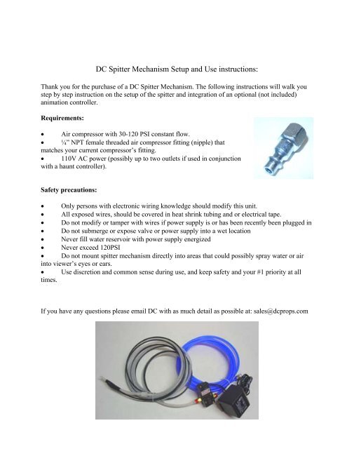
Requirements:<br />
• Air compressor with 30-120 PSI constant flow.<br />
• ¼” NPT female threaded air compressor fitting (nipple) that<br />
matches your current compressor’s fitting.<br />
• 110V AC power (possibly up to two outlets if used in conjunction<br />
with a haunt controller).<br />
Safety precautions:<br />
• Only persons with electronic wiring knowledge should modify this unit.<br />
• All exposed wires, should be covered in heat shrink tubing <strong>and</strong> or electrical tape.<br />
• Do not modify or tamper with wires if power supply is or has been recently been plugged in<br />
• Do not submerge or expose valve or power supply into a wet location<br />
• Never fill water reservoir with power supply energized<br />
• Never exceed 120PSI<br />
• Do not mount spitter mechanism directly into areas that could possibly spray water or air<br />
into viewer’s eyes or ears.<br />
• <strong>Use</strong> discretion <strong>and</strong> common sense during use, <strong>and</strong> keep safety <strong>and</strong> your #1 priority at all<br />
times.<br />
If you have any questions please email <strong>DC</strong> with as much detail as possible at: sales@dcprops.com
Setting up the <strong>Spitter</strong>:<br />
For the setup of the <strong>DC</strong> <strong>Spitter</strong> <strong>Mechanism</strong> first plan out placement of the spitter, triggering device<br />
<strong>and</strong> the valve <strong>and</strong> power supply. The power supply, controller <strong>and</strong> valve should never be used<br />
around water or in an area that is potentially exposed to water, <strong>and</strong> as an additional precautionary<br />
measure the valve should not be connected to a vessel or object or area that is electrically<br />
conductive (ie the side of a metal barrel containing or not containing water).<br />
Incase of the possibility of contact with water or moisture the valve <strong>and</strong> or power supply should<br />
also not be allowed to lie on the ground. We strongly suggest mounting the valve to a piece of<br />
wood <strong>and</strong> if possible onto a wall; out of any possible water<br />
exposure.<br />
With the valve <strong>and</strong> power supply configured, you can now run<br />
the spitter output (white ¼” tubing <strong>and</strong> the connected 5/32”<br />
siphon tube up, see picture) through your prop <strong>and</strong> out of the<br />
mouth or ejection area. Next run the black 5/32” siphon tube<br />
into a water reservoir. We suggest a 1 gallon milk jug or similar<br />
container, but DO NOT use any container that held any form of<br />
cleaner, detergent, bleach or other similar harmful chemical.<br />
The siphon tube (<strong>and</strong> main airline) can also be shortened to limit<br />
the amount of air <strong>and</strong> water travel to the ejection tip providing a<br />
quicker response time (IE, if there is 4’ of tubing coiled in front<br />
of the reservoir, cut that off). However measure twice <strong>and</strong> allow<br />
for a little slack before cutting anything.<br />
If you are using the spitter inside a barrel that is filled with water,<br />
cut off the tubing about a foot below the water level, while the<br />
prop is in its triggered position.<br />
The last portion of the basic setup is to add a ¼” NPT female<br />
threaded air compressor fitting (nipple) to the ¼” NPT push in<br />
fitting on the end of the air supply line. Thread the nipple fitting<br />
over the push in fitting, <strong>and</strong> tighten. We do not provide these<br />
with the mechanism due to the wide variety of fittings in<br />
circulation. Most common fittings are “IM” <strong>and</strong> avail in ¼”<br />
NPT <strong>and</strong> 3/8” NPT in almost all hardware stores, or online at<br />
www.mcmaster.com or www.harborfreight.com.<br />
With the air supply line connected to your compressor, <strong>and</strong> the<br />
valve, power supply, <strong>and</strong> tubing in place, simply plug in the<br />
power supply <strong>and</strong> within a second or two, your spitter will begin<br />
spitting a fine mist of water at your victims.
To adjust the flow of water, simply adjust the incoming PSI to the valve. The valve can run down<br />
to a minimum PSI of 30 <strong>and</strong> to a maximum of 120PSI.<br />
Wiring in a controller:<br />
Basic setup <strong>and</strong> integration of a “non-wired” manual trigger - (ie power cord or X-10<br />
system):<br />
By far the easiest (<strong>and</strong> cheapest) way to activate the valve setup is to manually plug in the power<br />
supply to a household wall receptacle. As mentioned above adding 110V to the power supply will<br />
switch the valves airflow, <strong>and</strong> extend the cylinder.<br />
Many people do not want to manually plug in a power supply for each activation, so the next<br />
easiest option is to integrate a wireless 120V appliance/light controller (available at<br />
www.dcprops.com). For about $40 you can wirelessly turn on <strong>and</strong> off the lifter from up to 40’<br />
away. For this setup, please follow the manufacturer’s <strong>instructions</strong> for setup <strong>and</strong> triggering.<br />
Basic setup <strong>and</strong> integration of a Push Button Trigger: (available at www.dcprops.com)<br />
If you are using a low voltage 12-24V valve <strong>and</strong><br />
manual triggering is preferred, a push button<br />
trigger is a great solution. To connect this type of<br />
triggering device first ensure the power supply is<br />
unplugged <strong>and</strong> had not been plugged in for at least<br />
10 minutes; the power supply holds power, <strong>and</strong> if it<br />
is or was recently plugged in, there is a possible<br />
shock hazard.<br />
With the power supply un-energized, take the<br />
power cord (running from the power supply to the<br />
valve) <strong>and</strong> separate (spilt apart) the two wires<br />
about a foot from the power supply. As a<br />
precaution, all wiring should be kept as far from<br />
the valve <strong>and</strong> water as possible. Once split you should be left with a solid black wire <strong>and</strong> a black<br />
wire with a white stripe.<br />
The black wire with the white stripe is the constant<br />
<strong>and</strong> you won’t touch that one. The solid black<br />
wire needs to be cut <strong>and</strong> the shielding stripped<br />
about 3/8 of an inch on each cut end. With both<br />
ends stripped, now you can connect the push<br />
button’s trigger.<br />
In the case of a <strong>DC</strong> h<strong>and</strong> held trigger (Pictured on<br />
right), you will want to connect the wire coming
from the power supply to the red wire, <strong>and</strong> the other cut side (the wire that’s running to the valve)<br />
to the black wire. We strongly recommend soldering these connections, then covering all of the<br />
bare wire with heat shrink tubing <strong>and</strong> or wrapping with electrical tape. WARNING - Only use<br />
h<strong>and</strong> held triggers with 12-24V <strong>DC</strong> setups, never integrate a h<strong>and</strong> held trigger into a 110V setup!<br />
With those connected, you have created a normally open circuit (switch that closes the connection<br />
turning on the valve) when the button is depressed.<br />
Basic setup <strong>and</strong> integration of a “relayed” animation controller:<br />
These <strong>instructions</strong> are for wiring a “relayed” controller, such as an Animation Maestro (available at<br />
www.dcprops.com). The manufacturer’s <strong>instructions</strong> supersede these <strong>instructions</strong>, so read <strong>and</strong><br />
follow those <strong>instructions</strong> <strong>and</strong> precautions prior to wiring.<br />
To connect a “common” relayed controller first<br />
ensure the power supply is un-energized <strong>and</strong> take<br />
the power cord that is running from the power<br />
supply to the valve <strong>and</strong> separate (spilt apart) the<br />
two wires about a foot from the power supply. As<br />
a precaution, all wiring should be kept as far from<br />
the valve <strong>and</strong> water as possible.<br />
Once split you should be left with a solid black<br />
wire <strong>and</strong> a black wire with a white stripe. The<br />
black wire with the white stripe is the constant <strong>and</strong><br />
you won’t touch that one. The solid black wire<br />
needs to be cut <strong>and</strong> the shielding stripped about 1/4<br />
of an inch on each cut end. With both ends<br />
stripped, now you can connect the first (common) wire coming from the power supply into the “C”<br />
(constant) terminal. Next connect the wire running to the valve on the lifter into the “N/O”<br />
(normally open) terminal.<br />
This will complete the circuit, <strong>and</strong> the controller will “close” the circuitry loop, per your program<br />
using a PIR (passive infrared) sensor, push button trigger, or switch mat (only connect ONE trigger<br />
at a time!).<br />
Basic setup <strong>and</strong> integration of a “powered” animation controller:<br />
These <strong>instructions</strong> are for wiring a “powered” controller, such as a Prop 1 micro controller or<br />
Sprawling Delusions Keybanger (using a 12V-24V main power supply, with 12V-24V output).<br />
This setup uses the power supply from the controller to power the valve, so in this setup you will<br />
want to cut the power supply off about 18” away from the power supply. Keep the power supply<br />
for future use, or for powering the controller.
With the power supply removed, separate (spilt apart) the two wires you just cut about 3” <strong>and</strong> strip<br />
approximately ¼” off each end. As a precaution, all wiring should be kept as far from the valve<br />
<strong>and</strong> water as possible. Once split you should be left with a solid black wire <strong>and</strong> a black wire with a<br />
white stripe.<br />
The black wire with the white stripe is the constant <strong>and</strong> will need to be connected into the “V+” or<br />
“POS” terminal. The solid black wire will need to be connected into one of the “N/O” (normally<br />
open) terminals.<br />
This will complete the circuit, <strong>and</strong> the program you enter into the controller, will control the<br />
opening <strong>and</strong> closing of the circuit (ie start <strong>and</strong> stop of the lift).<br />
Suggested Animation controllers:<br />
• Animation Maestro: great for triggering 1 item, extremely easy setup <strong>and</strong> real-time<br />
programming. Available from www.dcprops.com.<br />
• Animation Maestro 2: Great for triggering two items with real-time programming (ie spitter<br />
<strong>and</strong> a pneumatic solenoid valve). Available from www.dcprops.com.<br />
• SD Keybanger Lite: Great for triggering up to 2 items with extremely easy setup <strong>and</strong> realtime<br />
programming. Available from www.dcprops.com.<br />
• SD Keybanger: Great for triggering up to 6 items with extremely easy setup <strong>and</strong> real-time<br />
programming. Available from www.dcprops.com.<br />
• Basic Wireless Remote control: Extremely easy to use <strong>and</strong> wireless up to 40’. Available<br />
from www.dcprops.com.<br />
• Prop 1 Microcontroller: Great for triggering multiple items (up to 8), requires programming<br />
knowledge. Available from www.dcprops.com.<br />
• GF Minibrick 4 or 8: Great for triggering multiple items (up to 8), requires programming<br />
knowledge. Available from www.dcprops.com<br />
If you have any questions on these <strong>instructions</strong> or this props operation, please contact <strong>DC</strong> Design<br />
Studio at www.dcprops.com, support@dcprops.com. Please be safe <strong>and</strong> enjoy.<br />
Thanks again for your purchase <strong>and</strong> enjoy.<br />
<strong>DC</strong> Design Studio<br />
P.O. Box 132<br />
Mountain View, CA 94042<br />
www.dcprops.com
Here are a few additional pictures clients have found helpful: