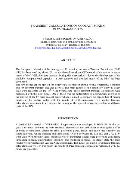
transient calculations of coolant mixing in vver-440/213 rpv
transient calculations of coolant mixing in vver-440/213 rpv
transient calculations of coolant mixing in vver-440/213 rpv

You also want an ePaper? Increase the reach of your titles
YUMPU automatically turns print PDFs into web optimized ePapers that Google loves.
TRANSIENT CALCULATIONS OF COOLANT MIXING<br />
IN VVER-<strong>440</strong>/<strong>213</strong> RPV<br />
Béla KISS, Ildikó BOROS, Dr. Attila ASZÓDI<br />
Budapest University <strong>of</strong> Technology and Economics<br />
Institute <strong>of</strong> Nuclear Techniques, Hungary<br />
kiss@reak.bme.hu, boris@reak.bme.hu, aszodi@reak.bme.hu<br />
ABSTRACT<br />
The Budapest University <strong>of</strong> Technology and Economics, Institute <strong>of</strong> Nuclear Techniques (BME<br />
NTI) has been work<strong>in</strong>g s<strong>in</strong>ce 2001 on the three-dimensional CFD model <strong>of</strong> the reactor pressure<br />
vessel <strong>of</strong> the VVER-<strong>440</strong> type reactors. Dur<strong>in</strong>g this time period – due to the development <strong>of</strong> the<br />
available computational capacity – a very complex and detailed model <strong>of</strong> the RPV has been<br />
developed.<br />
The new model can be applied for steady state calculation dur<strong>in</strong>g normal operational condition<br />
and for different <strong>transient</strong> analyses as well. The ma<strong>in</strong> results <strong>of</strong> the sensitivity study <strong>in</strong> steady<br />
state were presented on the 18 th AER Symposium. Three different <strong>transient</strong> <strong>calculations</strong> were<br />
performed with this new model. One <strong>of</strong> these was the participation <strong>in</strong> a benchmark exercise on<br />
the start-up <strong>of</strong> the 6 th ma<strong>in</strong> <strong>coolant</strong> pump, which is aimed to compare the capabilities <strong>of</strong> <strong>mix<strong>in</strong>g</strong><br />
models <strong>of</strong> 1D system codes with the results <strong>of</strong> CFD simulation. Two another <strong>transient</strong><br />
<strong>calculations</strong> were made to <strong>in</strong>vestigate the <strong>mix<strong>in</strong>g</strong> <strong>of</strong> the <strong>in</strong>jected emergency <strong>coolant</strong> <strong>in</strong> different<br />
parts <strong>of</strong> the RPV.<br />
INTRODUCTION<br />
A detailed RPV model <strong>of</strong> VVER-<strong>440</strong>/<strong>213</strong> type reactor was developed <strong>in</strong> BME NTI <strong>in</strong> the last<br />
year. This model conta<strong>in</strong>s the ma<strong>in</strong> structural elements as <strong>in</strong>let and outlet nozzles, guide baffles<br />
<strong>of</strong> hydro-accumulators, alignment drifts, perforated plates, brake- and guide tube chamber and<br />
simplified core. For the mesh<strong>in</strong>g and simulations ANSYS s<strong>of</strong>twares (ICEM-11.0 and CFX-11.0)<br />
were used. With the new vessel model a series <strong>of</strong> parameter studies were performed consider<strong>in</strong>g<br />
turbulence models, discretisation schemes, and model<strong>in</strong>g methods. In steady state the ma<strong>in</strong><br />
results were presented last year on AER Symposium. The model is suitable for different <strong>transient</strong><br />
<strong>calculations</strong> as well. In this paper the results <strong>of</strong> three <strong>transient</strong> simulations performed with this<br />
model are presented.
START UP OF THE 6 th MAIN COOLANT PUMP<br />
The purpose <strong>of</strong> the suggested benchmark was the comparison <strong>of</strong> calculation results with different<br />
codes on the effects <strong>of</strong> <strong>coolant</strong> <strong>mix<strong>in</strong>g</strong> <strong>in</strong> the VVER-<strong>440</strong>/<strong>213</strong> reactor vessel. The task <strong>of</strong> this<br />
benchmark is to <strong>in</strong>vestigate the start up <strong>of</strong> the 6th ma<strong>in</strong> <strong>coolant</strong> pump. A computation was carried<br />
out with the help <strong>of</strong> ATHLET/BIPR-VVER code <strong>in</strong> Kurchatov Institute for this <strong>transient</strong> and was<br />
repeated with ANSYS CFX 11.0 at our Institute.<br />
For the <strong>transient</strong> calculation a special vessel model has been used, which conta<strong>in</strong>ed the geometry<br />
only up to the core outlet (Fig 1). The pressure lost <strong>in</strong> the core and the effect <strong>of</strong> the core on the<br />
<strong>coolant</strong> flow was considered with a porous region model <strong>of</strong> the core. The SST turbulence model<br />
was selected for the calculation.<br />
Fig. 1: Model for the <strong>transient</strong> calculation<br />
The exam<strong>in</strong>ed situation was the start up <strong>of</strong> the 6 th loop while the other 5 loops are <strong>in</strong> normal<br />
operation. The <strong>coolant</strong> mass flow <strong>of</strong> the 6 th loop reaches the nom<strong>in</strong>al rate (~1400 kg/s) dur<strong>in</strong>g 20<br />
seconds (Fig 2).<br />
Fig. 2: Mass flow and temperature boundary conditions
The results show that the temperature gradient is steep <strong>in</strong> the vic<strong>in</strong>ity <strong>of</strong> the <strong>in</strong>let nozzle at the<br />
beg<strong>in</strong>n<strong>in</strong>g <strong>of</strong> the <strong>transient</strong>. It is an important result from the po<strong>in</strong>t <strong>of</strong> view <strong>of</strong> thermal stresses.<br />
The temperature distribution becomes homogenous at the end <strong>of</strong> the <strong>transient</strong> (Fig 3).<br />
Fig. 3: Temperature distribution on the wall <strong>of</strong> RPV<br />
ECS INJECTION INTO 2 nd , 3 rd AND 5 th COLD LOOPS<br />
Cold water was <strong>in</strong>jected <strong>in</strong>to the 2 nd , 3 rd and 5 th loops from the Emergency Cool<strong>in</strong>g System (ECS)<br />
dur<strong>in</strong>g the next <strong>transient</strong>. The <strong>in</strong>jection pipes are connected perpendicular to the cold leg loops<br />
from above. The boundary conditions <strong>of</strong> the simulation were calculated by APROS.<br />
The <strong>in</strong>jection starts <strong>in</strong> 10 th seconds. The mass flow <strong>of</strong> the <strong>in</strong>jected <strong>coolant</strong> (max. 13,5 kg/s) is<br />
significantly less compared to the mass flow <strong>of</strong> the loops (m<strong>in</strong>. 1510 kg/s). The temperature <strong>of</strong><br />
the ECCS <strong>coolant</strong> is 32 o C (Fig 4).
Mass flow and temperature <strong>of</strong> the <strong>coolant</strong> <strong>in</strong> the 6 loops<br />
Mass flow and temperature <strong>of</strong> the <strong>in</strong>jected water<br />
Fig. 4: Mass flow and temperature boundary conditions calculated by an APROS model<br />
The temperature <strong>of</strong> the RPV decreases dur<strong>in</strong>g the <strong>transient</strong>, but the effect <strong>of</strong> the <strong>in</strong>jected colder<br />
water is not considerable. The colder water does not have enough time for the <strong>mix<strong>in</strong>g</strong> <strong>in</strong>side the<br />
loop, the <strong>mix<strong>in</strong>g</strong> happens after enter<strong>in</strong>g <strong>in</strong>to the pressure vessel (Fig 5).
Fig. 5: Tempreature distribution on the wall <strong>of</strong> RPV and pipe<br />
ECS INJECTION ABOVE THE CORE<br />
The assumed <strong>in</strong>itial conditions <strong>of</strong> the next <strong>transient</strong>: the reactor is <strong>in</strong> hot shut down condition, i.e.<br />
the ma<strong>in</strong> <strong>coolant</strong> pumps are stopped. There is natural circulation <strong>in</strong> two loops (2 nd and 6 th loops<br />
are opened), the <strong>coolant</strong> mass flow rate <strong>in</strong> these two loops is 40 kg/s. The temperature <strong>of</strong> the<br />
<strong>coolant</strong> is 140 o C, the pressure is 0,5 MPa. The ECCS <strong>in</strong>jects water <strong>in</strong>to the 4 th loop and through<br />
the hydro-accumulator nozzles. The mass flow <strong>of</strong> the <strong>in</strong>jected water is 50 kg/s, the temperature is<br />
35 o C.<br />
The duration <strong>of</strong> the <strong>transient</strong> was 60 s. In the calculation buoyancy was taken <strong>in</strong>to account, and<br />
because <strong>of</strong> the large <strong>coolant</strong> temperature differences temperature dependent material properties<br />
were used.<br />
For this simulation only the core and the structural elements above the core were modelled <strong>in</strong><br />
details. The goal was to simulate the <strong>mix<strong>in</strong>g</strong> <strong>in</strong> the upper plenum so this is the reason why the<br />
lower plenum was neglected for this case.<br />
Fig. 6: The model <strong>of</strong> the core and the upper plenum<br />
The <strong>in</strong>jected water cools down the <strong>coolant</strong> <strong>in</strong> the 4 th loop and enters <strong>in</strong>to the vessel <strong>in</strong> the 23 rd<br />
second. The colder water flows around the perforated reactor pit and passes through the
perforations <strong>in</strong>to the upper plenum. The <strong>coolant</strong> through the hydro-accumulators flows directly<br />
onto the top <strong>of</strong> the core and flows down through the fuel assemblies.<br />
Fig. 7: Tempreature distribution on the wall<br />
The colder water <strong>of</strong> the ECCS cools down the fuel assemblies gradually dur<strong>in</strong>g the <strong>transient</strong>.<br />
Fig. 8: Tempreature distribution at the bottom <strong>of</strong> the core
The streaml<strong>in</strong>es show the flow path <strong>of</strong> the <strong>coolant</strong> through HA <strong>in</strong> the RPV. The water goes down<br />
directly <strong>in</strong>to the core and does not mix with the warmer water <strong>in</strong> the upper plenum.<br />
Fig. 9: Streaml<strong>in</strong>es <strong>in</strong> the pressure vessel<br />
SUMMARY<br />
In this paper the results <strong>of</strong> three <strong>transient</strong> simulations were presented, performed <strong>in</strong> the Budapest<br />
University <strong>of</strong> Technology and Economics, Institute <strong>of</strong> Nuclear Techniques (BME NTI). Due to<br />
the development <strong>of</strong> the available computational capability, it is already achievable to <strong>in</strong>clude the<br />
direct model <strong>of</strong> all <strong>in</strong>ternals <strong>in</strong> the CFD model <strong>of</strong> the pressure vessel. It opens the door to perform<br />
detailed simulations for different <strong>transient</strong> cases.<br />
Three different <strong>transient</strong> events were computed with the model. The performed simulations<br />
showed that the model is applicable for the computation <strong>of</strong> different cases.<br />
The first <strong>transient</strong> was the start up <strong>of</strong> the 6 th ma<strong>in</strong> <strong>coolant</strong> pump. The temperature distribution is<br />
very <strong>in</strong>homogeneous on the wall <strong>of</strong> the RPV at the beg<strong>in</strong>n<strong>in</strong>g <strong>of</strong> the <strong>transient</strong>.<br />
The second <strong>transient</strong> was the <strong>in</strong>jection from the ECS <strong>in</strong>to 2 nd , 3 rd and 5 th cold loops. The mass<br />
flow <strong>of</strong> the cold water was negligible compared to the mass flow <strong>of</strong> the loops so it did not have<br />
large <strong>in</strong>fluence.<br />
The third ones was the <strong>in</strong>jection from ECS <strong>in</strong>to the 4 th loop and through the nozzles <strong>of</strong> HA above<br />
the core.. The colder water fills the 4 th loop and flows <strong>in</strong>to the RPV. The <strong>coolant</strong> from HA flows<br />
down <strong>in</strong>to the core and starts to cool down the fuel assemblies.