Installation & Service Manual - Hillphoenix
Installation & Service Manual - Hillphoenix
Installation & Service Manual - Hillphoenix

You also want an ePaper? Increase the reach of your titles
YUMPU automatically turns print PDFs into web optimized ePapers that Google loves.
<strong>Installation</strong> & <strong>Service</strong><br />
<strong>Manual</strong><br />
NFJGCX, NCJGCX, NTJGCX, NFMJGCX,<br />
NFJGECX, NCJGECX<br />
GLASS FRONT JUMBO ISLAND FROZEN FOOD/ICE CREAM/<br />
MEDIUM TEMP MERCHANDISERS<br />
Low, Medium and Dual Temperature Self Serve Display Cases<br />
This manual has been designed to be used in conjunction with the<br />
General (UL/NSF) <strong>Installation</strong> & <strong>Service</strong> <strong>Manual</strong>.<br />
Save the Instructions in Both <strong>Manual</strong>s for Future Reference!!<br />
This merchandiser conforms to the American National Standard Institute & NEF International Health and Sanitation standard ANSI/NSF 7 - 2003.<br />
PRINTED IN Specifications subject to REPLACES ISSUE PART<br />
IN U.S.A. change without notice. EDITION 1/06 DATE 3/07 NO. 9037165 REV. F<br />
Tyler Refrigeration * Niles, Michigan 49120
NFJGCX, NCJGCX, NTJGCX,<br />
NFMJGCX, N(F/C)JGECX<br />
CONTENTS<br />
Page<br />
Specifications<br />
NFJGCX/NCJGCX/NTJGCX/NFMJGCX/NFJGECX/NCJGECX<br />
Specification Sheets . . . . . . . . . . . . . . . . . . . . . . . . . . . . . . . . . . . . . . 4<br />
Line Sizing Requirements . . . . . . (See General-UL/NSF I&S <strong>Manual</strong>)<br />
Pre-<strong>Installation</strong> Responsibilities . . . . . (See General-UL/NSF I&S <strong>Manual</strong>)<br />
<strong>Installation</strong> Procedures<br />
Carpentry Procedures . . . . . . . . . . . . . . . . . . . . . . . . . . . . . . . . . . . 7<br />
Case Pull-Up Locations . . . . . . . . . . . . . . . . . . . . . . . . . . . . . . . . . . 7<br />
1” Solid Partition . . . . . . . . . . . . . . . . . . . . . . . . . . . . . . . . . . . . . . . . 7<br />
Plexiglas Partition . . . . . . . . . . . . . . . . . . . . . . . . . . . . . . . . . . . . . . . 7<br />
Superstructure <strong>Installation</strong> . . . . . . . . . . . . . . . . . . . . . . . . . . . . . . . . . 7<br />
Trim <strong>Installation</strong>/Alignment . . . . . . . . . . . . . . . . . . . . . . . . . . . . . . . . . 9<br />
Bottom Tray . . . . . . . . . . . . . . . . . . . . . . . . . . . . . . . . . . . . . . . . . . . 9<br />
Plumbing Procedures . . . . . . . . (See General-UL/NSF I&S <strong>Manual</strong>)<br />
Refrigeration Procedures . . . . . . . . . . . . . . . . . . . . . . . . . . . . . . . 10<br />
Optional Dual Temperature Control . . . . . . . . . . . . . . . . . . . . . . . . . 10<br />
Electrical Procedures . . . . . . . . . . . . . . . . . . . . . . . . . . . . . . . . . . . 11<br />
Electrical Considerations . . . . . . . . . . . . . . . . . . . . . . . . . . . . . . . . . 11<br />
Defrost Information . . . . . . . . . . . . . . . . . . . . . . . . . . . . . . . . . . . . 11<br />
Defrost Control Chart . . . . . . . . . . . . . . . . . . . . . . . . . . . . . . . . . . . 11<br />
Defrost Schedules . . . . . . . . . . . . . . . . . . . . . . . . . . . . . . . . . . . . . . 12<br />
<strong>Installation</strong> Procedure Check Lists (See General-UL/NSF I&S Man.)<br />
Wiring Diagrams . . . . . . . . . . . . . . . . . . . . . . . . . . . . . . . . . . . . . . . . . . . 12<br />
NFJGCX/NCJGCX Domestic & Export (50Hz) Case Circuits . . 13<br />
NTJGCX/NFMJGCX Domestic & Export (50Hz) Case Circuits . 15<br />
NFJGECX/NCJGECX Dom. & Exp. (50Hz) End Case Circuits . 17<br />
NTJGCX/NFMJGCX Dual Temperature Control Circuits . . . . . . 18<br />
NFJGCX/NCJGCX Dual Temperature Control Circuits . . . . . . . 20<br />
NFJGECX Dual Temperature Control Circuits . . . . . . . . . . . . . 22<br />
Optional Superstructure Wiring Circuits . . . . . . . . . . . . . . . . . . . 23<br />
Cleaning and Sanitation . . . . . . . . . . . . (See General-UL/NSF I&S <strong>Manual</strong>)<br />
Component Removal and <strong>Installation</strong> Instructions for Cleaning 24<br />
Bottom Screens and Trays . . . . . . . . . . . . . . . . . . . . . . . . . . . . . . . 24<br />
NSF Product Thermometer . . . . . . . . . . . . . . . . . . . . . . . . . . . . . . 24<br />
Discharge Air Honeycomb . . . . . . . . . . . . . . . . . . . . . . . . . . . . . . . . 24<br />
Discharge Air Duct Panels . . . . . . . . . . . . . . . . . . . . . . . . . . . . . . . 24<br />
Return Air Ducts Panels . . . . . . . . . . . . . . . . . . . . . . . . . . . . . . . . 24<br />
Corner Trim . . . . . . . . . . . . . . . . . . . . . . . . . . . . . . . . . . . . . . . . . . . 24<br />
Front Cladding . . . . . . . . . . . . . . . . . . . . . . . . . . . . . . . . . . . . . . . . 24<br />
Page 2 March, 2007
<strong>Installation</strong> & <strong>Service</strong> <strong>Manual</strong><br />
NFJGCX, NCJGCX, NTJGCX,<br />
NFMJGCX, N(F/C)JGECX<br />
Page<br />
<strong>Service</strong> Instructions<br />
Preventive Maintenance . . . . . . (See General-UL/NSF I&S <strong>Manual</strong>)<br />
NSF Product Thermometer Replacement . . . . . . . . . . . . . . . . . . 25<br />
Corner Trim Replacement . . . . . . . . . . . . . . . . . . . . . . . . . . . . . . . 25<br />
Perimeter Glass Replacement . . . . . . . . . . . . . . . . . . . . . . . . . . . 26<br />
Defrost Heater Replacement . . . . . . . . . . . . . . . . . . . . . . . . . . . . . .26<br />
Drain Pan Heater Replacement . . . . . . . . . . . . . . . . . . . . . . . . . . . 27<br />
Fan Blade and Motor Replacement (See General-UL/NSF I&S Man.)<br />
Anti-Sweat Replacement . . . . . . . . . . . . . . . . . . . . . . . . . . . . . . . . 27<br />
Glass Retainer Anti-Sweat (All Models) . . . . . . . . . . . . . . . . . . . . . . 27<br />
Center Riser Discharge Air Grid Anti-Sweat<br />
(NFJGCX/NCJGCX/NTJGCX/NFMJGCX) . . . . . . . . . . . . . . . . . . . . 28<br />
Discharge Air Grid Anti-Sweat (NFJGECX/NCJGECX) . . . . . . . . . . 28<br />
Color Band and Bumper Replacement (See Gen.-UL/NSF I&S Man.)<br />
Parts Information<br />
Operational Parts List . . . . . . . . . . . . . . . . . . . . . . . . . . . . . . . . . . 29<br />
Cladding and Trim Parts Lists . . . . . . . . . . . . . . . . . . . . . . . . . . . . 30<br />
TYLER Warranty . . . . . . . . . . . . . . . . . (See General-UL/NSF I&S <strong>Manual</strong>)<br />
The following Frozen Food, Ice Cream, Medium Temperature and Dual Temperature<br />
Split Coil Merchandiser models are covered in this manual:<br />
MODEL<br />
NFJGCX<br />
NCJGCX<br />
NTJGCX<br />
DESCRIPTION<br />
8’ & 12’ GLASS FRONT JUMBO ISLAND FROZEN FOOD OR<br />
MEDIUM TEMPERATURE MERCHANDISERS<br />
8’ & 12’ GLASS FRONT JUMBO ISLAND ICE CREAM<br />
MERCHANDISERS<br />
8’ & 12’ GLASS FRONT JUMBO ISLAND LOW AND MEDIUM<br />
TEMPERATURE DUAL TEMP SPLIT COIL MERCHANDISERS<br />
NFMJGCX 8’ & 12’ GLASS FRONT JUMBO ISLAND LOW AND MEDIUM<br />
TEMPERATURE DUAL TEMP SPLIT COIL MERCHANDISERS<br />
NFJGECX GLASS FRONT JUMBO ISLAND FROZEN FOOD OR MEDIUM<br />
TEMPERATURE END MERCHANDISER<br />
NCJGECX GLASS FRONT JUMBO ISLAND ICE CREAM END MERCHANDISER<br />
March, 2007 Page 3
NFJGCX, NCJGCX, NTJGCX,<br />
NFMJGCX, N(F/C)JGECX<br />
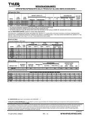
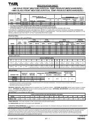
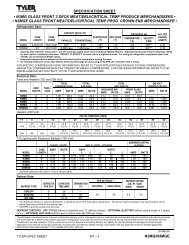
SPECIFICATIONS<br />
NFJGCX/NCJGCX/NTJGCX/NFMJGCX/NFJGECX/NCJGECX Glass Front<br />
Jumbo Island and End Frozen Food/Ice Cream/Med Temp Merchandisers<br />
Page 4 March, 2008
<strong>Installation</strong> & <strong>Service</strong> <strong>Manual</strong><br />
NFJGCX, NCJGCX, NTJGCX,<br />
NFMJGCX, N(F/C)JGECX<br />
March, 2008 Page 5
NFJGCX, NCJGCX, NTJGCX,<br />
NFMJGCX, N(F/C)JGECX<br />
Page 6 March, 2008
<strong>Installation</strong> & <strong>Service</strong> <strong>Manual</strong><br />
INSTALLATION PROCEDURES<br />
Carpentry Procedures<br />
Case Pull-Up Locations<br />
NFJGCX, NCJGCX, NTJGCX,<br />
NFMJGCX, N(F/C)JGECX<br />
Plexiglas Partition<br />
A plexiglas plug partition is required on adjacent<br />
electric defrost cases that are on different<br />
defrost schedules. These partitions can<br />
be installed after the cases have been joined.<br />
The NFJGCX/NCJGCX/NTJGCX/NFMJGCX<br />
models have two pull-ups at each end of the<br />
case. Pull-ups A and B are located as shown<br />
and used for joining all cases. The NFJGECX<br />
and NCJGECX models have four pull-ups at<br />
the rear of the case. Pull-ups A, B, C and D<br />
are located as shown and used for joining end<br />
cases. Pull-ups C and D are shipped loose.<br />
All pull-ups should be installed and tightened<br />
starting with A and finishing with B or D.<br />
1” Solid Partition<br />
A 1” insulated partitions is required between<br />
adjacent gas defrost cases that are on different<br />
defrost schedules. 1” partitions are shipped<br />
installed as specified in the case order. Make<br />
sure the partitioned case is being installed in<br />
the proper location in the case line-up. This<br />
assures proper refrigeration to all parts of the<br />
case line-up.<br />
Apply sealant to outside surface of partition<br />
where the two surfaces of the adjoining case<br />
will contact the partition.<br />
See “General-UL/NSF I&S <strong>Manual</strong>” for<br />
line-up assembly instructions.<br />
After all case pull-ups have been secured, seal<br />
all interior wall joint seams with duct tape.<br />
1. Install partition brackets (1) at case joint<br />
on front, center and/or rear case wall (2)<br />
with screws 3)<br />
2. Slide plexiglas partitions (4) into partition<br />
brackets (1).<br />
Superstructure <strong>Installation</strong><br />
Make sure discharge air grids are removed.<br />
Remove top riser cap knockouts and insulation<br />
on top of the center partition from the<br />
superstructure end sockets and the upright<br />
support angles.<br />
1. If the wiring harness has not been factory<br />
installed, remove insulation from top of<br />
center riser and lay wire harnesses (1) on<br />
top of the center partition (2). The 8’ harness<br />
has three female plugs and one<br />
male plug. The 12’ harness has four<br />
female plugs and one male plug. There is<br />
one harness for shelf anti-sweat heaters<br />
and one for the shelf lights. The sockets<br />
are not interchangeable. The anti-sweat<br />
harness male plug connects at the RH<br />
March, 2007 Page 7
NFJGCX, NCJGCX, NTJGCX,<br />
NFMJGCX, N(F/C)JGECX<br />
post socket. The light harness male plug<br />
goes down the RH post socket (3) and<br />
plugs into the matching receptacle in the<br />
115V case wiring block (4). Replace<br />
insulation.<br />
2. Position the RH end post (5) in the RH<br />
superstructure hole in the center riser (3).<br />
Install the two plugs (6) and push them<br />
into the insulation. Push down the RH<br />
end post (5) until it seats into the center<br />
riser (3) and secure with four bolts (7).<br />
NOTE<br />
On 12’ cases, the electrical outlets on the<br />
center posts must face the end posts.<br />
3. Install and align the center upright (10) to<br />
base plate (8) and angle brackets (9) with<br />
four adjustment bolts (11). The center<br />
uprights may face in either direction.<br />
Connect upright wire plugs (12) to<br />
harness. Route wires and harness<br />
around the uprights in the insulation.<br />
NOTE<br />
Items 8 and 9 will be shipped loose on<br />
superstructures ordered through TYLER<br />
<strong>Service</strong> Parts Department. Separate<br />
installation instructions will be provided<br />
with the superstructures.<br />
4. Install the LH end post (13) as described in<br />
step 2.<br />
NOTE<br />
Notches on upright alignment channel will<br />
help position the channels properly.<br />
5. Position the upright alignment channel (14)<br />
on top of the upright posts (13). Using the<br />
holes in the upright alignment channel as a<br />
guide, drill 1/8” pilot holes in the upright<br />
posts (13) and secure with screws (15).<br />
6. Install each pair of shelf brackets (16) in<br />
slots in upright posts (13). Use one RH<br />
and one LH bracket per shelf. Superstructures<br />
with end shelves have angled<br />
brackets on the end shelf uprights (13).<br />
7. Position shelves (17) on shelf brackets (16)<br />
and install front alignment screws (18).<br />
8. Install shelving close-offs (19) in space<br />
between shelves. The close-offs are<br />
supported by the shelf brackets (16). If<br />
end close-offs (20) are supplied, they are<br />
also secured to the shelf brackets (16).<br />
Page 8 March, 2007
<strong>Installation</strong> & <strong>Service</strong> <strong>Manual</strong><br />
NFJGCX, NCJGCX, NTJGCX,<br />
NFMJGCX, N(F/C)JGECX<br />
9. Plug in the shelf anti-sweat heaters (21)<br />
and shelf lights (22).<br />
NOTE<br />
Notches on upright alignment channel will<br />
help position the channels properly.<br />
Trim <strong>Installation</strong>/Alignment<br />
See “General-UL/NSF I&S <strong>Manual</strong>” for<br />
bumper, color band, raceway and kickplate<br />
installation.<br />
Corner Trim <strong>Installation</strong><br />
Most corner trim on these cases comes<br />
fac-tory installed. The kickplate corner trim<br />
requires field installation.<br />
10. Install top riser caps (23) on top of the<br />
center partition. Drill pilot holes in the top<br />
center of the two riser caps and secure<br />
with screws (24).<br />
11. Position card moulding (25) as shown and<br />
drill 1/8” pilot holes in riser caps (23).<br />
Secure card mouldings (25) to riser caps<br />
(23) with screws (26).<br />
After kickplates (1) have been installed, position<br />
kickplate corner trim (2) over both ends<br />
of the kickplates (1) and secure with screws.<br />
Bottom Trays<br />
CAUTION<br />
Placing product directly on bottom trays<br />
could break a bottom tray and/or caise<br />
damage to the case.<br />
The bottom trays are made from polypropylene.<br />
They are designed to be non-weight<br />
bearing. After the bottom trays have been<br />
installed, be sure to install the bottom screens<br />
before stocking the case with product.<br />
Plumbing Procedures<br />
See “General-UL/NSF I&S <strong>Manual</strong>” for<br />
recommended drain practices.<br />
March, 2007 Page 9
NFJGCX, NCJGCX, NTJGCX,<br />
NFMJGCX, N(F/C)JGECX<br />
Refrigeration Procedures<br />
See “General-UL/NSF I&S <strong>Manual</strong>” for<br />
general system, control and superheat<br />
information.<br />
There are four standard versions of the 8’ and<br />
12’ cases.<br />
NFJGCX is for frozen food or medium temp<br />
usage and is equipped with one electric<br />
defrost heater on each side. The entire case,<br />
both sides, will operate at low or medium<br />
temperatures.<br />
NCJGCX is for ice cream usage and is<br />
equipped with one electric defrost heater on<br />
each side. The entire case, both sides, runs<br />
from a single refrigeration system.<br />
NTJGCX and NFMJGCX are dual temp split<br />
coil cases. The NTJGCX version is for ice<br />
cream on one side and frozen food on the<br />
other The NFMJGCX version is for frozen<br />
food on both sides. Both versions are<br />
equipped with one electric defrost heater on<br />
each side. These cases also have an insulated<br />
center partition to aid in maintaining the<br />
temperature difference in the two side. This<br />
allows either side of the case to run from separate<br />
refrigeration systems.<br />
The NTJGCX or NFMJGCX cases can also be<br />
set up to display frozen food on one side and<br />
medium temp on the other. Either side can<br />
be optionally set up with a dual temperature<br />
control to allow one side to be switched<br />
between low temp and medium temp operations.<br />
The evaporator coils are piped individually<br />
so there are two refrigeration stub-ups.<br />
The NFJGCX case can also be set up for dual<br />
temperature operations, but the evaporator<br />
coils are piped together so there is only one<br />
refrigeration stub-up. This case requires<br />
extra refrigeration components to allow it to<br />
perform dual temperature operations.<br />
NFJGCX or NFMJGCX cases set up for electric<br />
defrost medium temp applications utilize<br />
the standard defrost heaters. Gas defrost<br />
medium temp applications incorporate a fan<br />
delay klixon.<br />
Optional Dual Temperature Control<br />
The dual temperature control unit is a factory<br />
installed option. This control allows the user<br />
to easily switch from medium to low temperature<br />
operation by flipping a switch. The dual<br />
temperature control consists of an EPR valve<br />
in the suction line coming off the evaporator.<br />
The EPR valve can be bypassed with a solenoid<br />
controlled bypass line around it. The<br />
toggle switch opens or closes this solenoid.<br />
Gas Defrost Dual<br />
Temperature Controls<br />
with EPR Valve<br />
Electric Defrost Dual<br />
Temperature Controls<br />
with EPR Valve<br />
When the solenoid is open, the evaporator is<br />
connected directly to the compressor suction<br />
that allows for low temperature operation.<br />
When the solenoid is closed, the evaporator<br />
must operate through the EPR valve which<br />
has been preset to the desired medium<br />
temperature.<br />
EXAMPLE: R-404A system with 14 psig of<br />
suction pressure. With the suction line<br />
solenoid open, the coil pressure operates at<br />
14 psig with a temperature of -25°F. When<br />
toggle switch is flipped, the solenoid closes<br />
directing the flow through the EPR valve. If<br />
the EPR valve is set for 49.5 psig, the evaporator<br />
will see a coil temperature of 15°F and<br />
will operate at a discharge air temperature<br />
of about 22°F.<br />
When gas defrost is used, an additional<br />
check valve is mounted around the EPR<br />
valve to allow reverse flow for the defrosting<br />
gas. A fan delay is also connected with gas<br />
defrost to cycle the fans off, but only during<br />
the medium temperature mode.<br />
Page 10 March, 2007
<strong>Installation</strong> & <strong>Service</strong> <strong>Manual</strong><br />
NFJGCX, NCJGCX, NTJGCX,<br />
NFMJGCX, N(F/C)JGECX<br />
Electrical Procedures<br />
Electrical Considerations<br />
CAUTION<br />
Make sure all electrical connections at<br />
components and terminal blocks are tight.<br />
This prevents burning of electrical terminals<br />
and/or premature component failure.<br />
NOTE<br />
• The raceway houses the electrical wiring<br />
and components for the case. All<br />
raceway covers will be shipped loose.<br />
• The NFJGCX or NFMJGCX case does not<br />
require the heated perimeter glass when<br />
used for medium temp operation. The<br />
glass heater should be disconnected<br />
from the terminal block.<br />
• Cases equipped with optional dual<br />
temperature control will de-energize<br />
the perimeter glass with klixon when<br />
switched to medium temp operation.<br />
Case Fan Circuit<br />
This circuit is to be supplied by an uninterrupted,<br />
protected 120V circuit. Cases being used<br />
for Low Temp applications with electric or gas<br />
defrost, keep fans on all the time. Cases<br />
being used for Medium Temp applications<br />
with electric defrost, also keep fans on all the<br />
time. Cases being used for Medium Temp<br />
applications with gas defrostm cycle fans with<br />
a 50/40 klixon.<br />
Anti-Sweat Circuit<br />
NFJGCX/NCJGCX/NTJGCX/NFMJGCX cases<br />
have one anti-sweat heater on each side of the<br />
top of the center riser (discharge air) and one<br />
under each perimeter glass retainer. When<br />
cases are equipped with an optional superstructure,<br />
there is an anti-sweat heater on the<br />
superstructure. NFJGECX and NCJGECX end<br />
cases have one anti-sweat heater in the discharge<br />
air grid and one under each perimeter<br />
glass retainer. The perimeter glass<br />
is also heated on all models. Anti-sweat<br />
heaters are wired directly to the main power<br />
supply so it can operate at all times.<br />
Superstructure Shelf Lamp Circuit<br />
Optional superstructures can be equipped<br />
with one row of 430MA T-12 or 265MA T-8<br />
shelf lights.<br />
Defrost Information<br />
See “General-UL/NSF I&S <strong>Manual</strong>” for<br />
operational descriptions for each type of<br />
defrost control.<br />
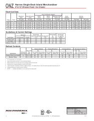
Defrost Control Chart<br />
Defrost<br />
Defrost Defrosts Duration Term.<br />
Type Per Day (Min) Temp.<br />
Electric/FF 1 60 50°F<br />
Electric/IC 1 36 50°F<br />
Electric/MED 1 36 50°F<br />
Gas/FF 2-3 20-25 55°F<br />
Gas/IC 2-3 25-30 55°F<br />
Gas/MED 2-3 16-20 55°F<br />
Most klixons are located on the right end of<br />
the evaporator coil. The diagram shows the<br />
location for each defrost type that uses a<br />
klixon.<br />
NOTE<br />
The termination klixon for gas defrost is<br />
located at the bypass check valve.<br />
CAUTION<br />
If electronic sensors are used in place of<br />
the klixons, the sensors must be located<br />
in the same location as the klixons for that<br />
defrost type. Any other locations will<br />
effect the refrigeration efficiency of the<br />
case.<br />
March, 2007 Page 11
NFJGCX, NCJGCX, NTJGCX,<br />
NFMJGCX, N(F/C)JGECX<br />
Defrost Schedules<br />
For satisfactory performance, both sides of<br />
the case should be scheduled to defrost at<br />
the same time. This holds true even when<br />
both sides run from different machines.<br />
Two Single Machines Use the defrost clock<br />
which controls one of the machines and run<br />
a relay to control the other machine. Defrost<br />
load is spread across clock contacts and<br />
extra contactors (as required).<br />
Parallel with Electric Defrost and Dual<br />
Temp or Dual Temp Split Coil Operation<br />
use one station of the multi-circuit time clock<br />
to control the defrost circuit breakers for the<br />
cases defrost heaters. This ensures both<br />
sides defrost at the same time.<br />
Parallel with Gas Defrost (NTJGCX or<br />
NFMJGCX only) Make sure that only 25% of<br />
the combined load (frozen food & ice cream<br />
or frozen food & medium temp.) is on one<br />
circuit. Use one station of the multi-circuit<br />
time clock to control the booster circuit and<br />
that portion of the frozen food cases opposite<br />
the ice cream side.<br />
Gas defrosting is only available as an option<br />
on cases operated from a parallel system.<br />
About 25% of the cases can be defrosted at<br />
one time. This allows the refrigeration heat<br />
being removed from the cases to be used to<br />
defrost the others.<br />
NOTE<br />
Insulated partitions must be used between<br />
case line-ups that have gas defrost!<br />
Single Temp cases (NFJGCX/NCJGCX/<br />
NFJGECX/NCJGECX) have individual coil<br />
piping that needs to be joined at installation<br />
when both sides and/or ends are on the<br />
same system. Dual Temp Split Coil cases<br />
(NTJGCX/NFMJGCX) with gas defrost should<br />
be piped to their respective systems and<br />
defrosts should be scheduled at the same<br />
time. Each coil requires a separate defrost<br />
termination klixon at the check valve.<br />
WIRING DIAGRAMS<br />
ELECTRICIAN NOTE - OVERCURRENT<br />
PROTECTION<br />
120V circuits should be protected by 15 or 20 Amp<br />
devices per the requirements noted on the cabinet<br />
nameplate or the National Electrical Code, Canadian<br />
Electrical Code - Part 1, Section 28. 208V defrost<br />
circuits employ No. 12 AWG field wire leads for field<br />
connections. On remote cases intended for end to<br />
end line-ups, bonding for ground may rely upon the<br />
pull-up bolts.<br />
The following wiring diagrams on pages 13<br />
thru 23 will cover the NFJGCX/NCJGCX/<br />
NTJGCX/NFMJGCX/NFJGECX/NCJGECX<br />
case circuits, electric defrost circuit, gas<br />
defrost circuit, dual temperature control<br />
circuits and the superstructure wiring circuit.<br />
Page 12 March, 2007
NFJGCX/NCJGCX Domestic & Export (50 Hz) Case Circuits<br />
March, 2007 Page 13
Page 14 March, 2008
NTJGCX/NFMJGCX Domestic & Export (50 Hz) Case Circuits<br />
March, 2007 Page 15
Page 16 March, 2008
NFJGECX/NCJGECX Domestic & Export (50 Hz) End Case Circuits<br />
March, 2007 Page 17
NTJGCX/NFMJGCX Dual Temperature Control Circuits<br />
Page 18 March, 2007
March, 2008 Page 19
NFJGCX/NCJGCX Dual Temperature Control Circuits<br />
Page 20 March, 2007
March, 2008 Page 21
NFJGECX Dual Temperature Control Circuits<br />
Page 22 March, 2007
<strong>Installation</strong> & <strong>Service</strong> <strong>Manual</strong><br />
NFJGCX, NCJGCX, NTJGCX,<br />
NFMJGCX, N(F/C)JGECX<br />
Optional Superstructure Wiring Circuit<br />
March, 2007 Page 23
NFJGCX, NCJGCX, NTJGCX,<br />
NFMJGCX, N(F/C)JGECX<br />
CLEANING AND SANITATION<br />
Component Removal and<br />
<strong>Installation</strong> Instructions for<br />
Cleaning<br />
Bottom Screens and Trays<br />
1. Remove product from bottom screens.<br />
2. Push screens up until bottom screen tabs<br />
clear the holes in the front duct.<br />
3. Remove bottom screens from holes in<br />
center riser panel and from case.<br />
4. Grasp and lift out each of the bottom trays<br />
from the case interior.<br />
5. After cleaning, replace in reverse order.<br />
Bottom tray should have ribs up.<br />
CAUTION<br />
Do not place product directly on bottom<br />
trays. Doing so could break a bottom tray<br />
and/or cause damage to the case.<br />
NSF Product Thermometer<br />
Remove two screws and product thermometers<br />
from top, right end of front and rear<br />
return air ducts. After cleaning, replace<br />
product thermometers on front and rear<br />
ducts and secure with screws.<br />
Discharge Air Honeycomb<br />
1. Remove screws and bottom retainer strip<br />
from both sides of the top of the center riser<br />
(NFJGCX/NCJGCX/NTJGCX/NFMJGCX)<br />
or from rear riser (NFJGECX/NCJGECX).<br />
NOTE<br />
Note position of the honeycomb grid during<br />
removal so it can be reinstalled the<br />
same way.<br />
2. Remove honeycomb grid sections from<br />
both sides of the center riser or from rear<br />
riser.<br />
CAUTION<br />
Improper installation of the honeycomb<br />
grid section could result in improper air<br />
flow and/or poor refrigeration.<br />
3. After cleaning, replace honeycomb grid<br />
sections as they were removed and<br />
secure with the bottom retainer strip<br />
and screws.<br />
Discharge Air Duct Panels<br />
1. Remove bottom screens, bottom trays<br />
and discharge air honeycomb, see this<br />
page.<br />
2. Remove mounting screws and discharge<br />
air duct panels from both sides of the<br />
center riser (NFJGCX/NCJGCX/NTJGCX/<br />
NFMJGCX).<br />
-- or --<br />
Remove mounting screws and discharge<br />
air duct panels (NFJGECX/NCJGECX).<br />
3. After cleaning, replace in reverse order.<br />
Return Air Duct Panels<br />
1. Remove bottom screens, bottom trays<br />
and discharge air honeycomb, see this<br />
page.<br />
2. Remove mounting screws and front and<br />
rear return air duct panels<br />
(NFJGCX/NCJGCX/NTJGCX/NFMJGCX).<br />
-- or --<br />
Remove mounting screws and front return<br />
air duct panels (NFJGECX/NCJGECX).<br />
3. After cleaning, replace in reverse order.<br />
Corner Trim<br />
1. See page 22 for corner trim removal<br />
instructions.<br />
2. After cleaning trim and cladding components,<br />
replace front cladding and corner<br />
trim components in reverse orde using<br />
instructions below and on page 22.<br />
Front Cladding<br />
1. Remove front kickplate and raceway<br />
cover.<br />
2. Remove screws from bottom and top of<br />
front cladding and pull cladding down to<br />
remove it from behind the bottom edge of<br />
the bumper retainer.<br />
3. After cleaning, replace front cladding and<br />
remaining front components in reverse<br />
order.<br />
Page 24 March, 2007
<strong>Installation</strong> & <strong>Service</strong> <strong>Manual</strong><br />
SERVICE INSTRUCTIONS<br />
See “General-UL/NSF I&S <strong>Manual</strong>” for fan<br />
blade and motor replacement, color band<br />
and bumper replacement and raceway<br />
cover removal instructions.<br />
NSF Product Thermometer<br />
Replacement<br />
NFJGCX, NCJGCX, NTJGCX,<br />
NFMJGCX, N(F/C)JGECX<br />
Corner Trim Replacement<br />
Since some of the corner trim fasteners are<br />
hidden, remove the trim and hardware in the<br />
following sequence.<br />
1. Remove two screws (1) and thermometer<br />
(2) from top right end of front or rear<br />
return air ducts.<br />
2. Install and secure a new product thermometer<br />
(2) on front or rear return air<br />
duct with two screws (1).<br />
1. Remove kickplates (1) and kickplate<br />
corner trim (2) from both sides of the<br />
corner trim.<br />
2. Remove raceway covers (3) from both<br />
sides of the corner trim.<br />
3. Remove two screws (4) and corner<br />
cladding trim (5).<br />
4. Remove two top screws (6) from the<br />
raceway corner trim (7), then lift and<br />
remove the raceway corner trim from the<br />
retainers in the bottom slots.<br />
5. Remove two bottom screws (8) and lift off<br />
the bumper corner/glass trim (9).<br />
6. Replace corner/glass trim, raceway corner<br />
trim, corner cladding trim, raceway covers<br />
and kickplates in reverse order.<br />
March, 2007 Page 25
NFJGCX, NCJGCX, NTJGCX,<br />
NFMJGCX, N(F/C)JGECX<br />
Perimeter Glass Replacement<br />
NOTE<br />
End cases require corner trim removal<br />
before replacing the glass. See “Corner<br />
Trim Replacement” in this manual.<br />
Defrost Heater Replacement<br />
WARNING<br />
Always shut off electricity to case before<br />
replacing a defrost heater. Automatic<br />
cycling of fans or electrical power to wire<br />
ends could cause personal injury and/or<br />
death.<br />
1. Remove bottom trays from case.<br />
1. Unplug glass anti-sweat wires (1).<br />
2. Remove two screws (2) and glass joint trim<br />
(3) from both joints of the broken glass (4).<br />
3. Remove screws (5) and glass trim rail (6)<br />
from top of glass (4).<br />
4. Loosen rear retainer (7) and remove broken<br />
glass from glass retainer assembly (8).<br />
NOTE<br />
Inspect the anti-sweat wire in glass retainer<br />
assembly. If wire is damaged or broken,<br />
replace it before replacing the front glass.<br />
5. Apply sealant tape to top and bottom edge<br />
of new glass (4).<br />
6. Position new glass (4) in glass retainer<br />
assembly (8) and secure by tightening rear<br />
retainer (7).<br />
7. Install glass trim rail (6) with screws (5) over<br />
top edge of new glass (4).<br />
8. Install glass joint trim (3) with screws (2)<br />
over the joint areas of glass (4).<br />
9. Reconnect the anti-sweat wires (1).<br />
2. Unscrew and remove top coil cover (1).<br />
3. Unscrew and lift up fan plenum (2).<br />
4. Disconnect defective defrost heater (3)<br />
and remove mounting clips (4) and<br />
defrost heater (3) from front of coil<br />
assembly (5).<br />
5. Install new defrost heater (3) in reverse<br />
order.<br />
6. Restore electrical power to case.<br />
Page 26 March, 2007
<strong>Installation</strong> & <strong>Service</strong> <strong>Manual</strong><br />
Drain Pan Heater Replacement<br />
WARNING<br />
Always shut off electricity to case before<br />
replacing a drain pan heater. Automatic<br />
cycling of fans or electrical power to wire<br />
ends could cause personal injury and/or<br />
death.<br />
1. Remove bottom trays from case.<br />
NFJGCX, NCJGCX, NTJGCX,<br />
NFMJGCX, N(F/C)JGECX<br />
Anti-Sweat Heater Replacement<br />
WARNING<br />
Shut off or disconnect power supply to<br />
case before changing an anti-sweat.<br />
Electrical power from wire ends could<br />
damage other components and/or cause<br />
personal injury or death.<br />
Glass Retainer Anti-Sweat (All Models)<br />
NOTE<br />
• Perimeter glass must be removed from<br />
glass retainer. See “Perimeter Glass<br />
Replacement” in this manual.<br />
• Corner cases require removal of all<br />
raceway covers, cladding, corner trim,<br />
bumpers and bumper retainers.<br />
2. Unlug defective drain pan heater (1) and<br />
remove from slots in bracket supports (2).<br />
3. Install new drain pan heater (1) in reverse<br />
order.<br />
4. Restore electrical power to case.<br />
1. Disconnect or cut the defective anti-sweat<br />
wires (1) from the case wires.<br />
2. Remove and replace the aluminum tape<br />
(2) and defective anti-sweat wire (1) from<br />
the bottom of the front glass retainer (3).<br />
3. Reconnect the anti-sweat wires to case<br />
wires .<br />
4. Replace the perimeter glass and any<br />
other trim or cladding that was removed.<br />
March, 2007 Page 27
NFJGCX, NCJGCX, NTJGCX,<br />
NFMJGCX, N(F/C)JGECX<br />
Center Riser Discharge Air Anti-Sweat<br />
(NFJGCX/NCJGCX/NTJGCX/NFMJGCX)<br />
Discharge Air Grid Anti-Sweat<br />
(NFJGECX/NCJGECX)<br />
1. Remove screws (1) and top riser caps (2)<br />
and insulation from top of center riser (3).<br />
2. Disconnect or cut the defective anti-sweat<br />
wire (4) from the case wires.<br />
3. Remove and replace the aluminum tape<br />
and defective anti-sweat wire (4) from the<br />
bottom of the top riser cap (2).<br />
4. Reconnect the new anti-sweat wires to<br />
case wires and reinstall the insulation, top<br />
riser caps and screws.<br />
1. Remove screws and rear guard trim (1)<br />
from top of rear case wall (2).<br />
2. Disconnect or cut the defective anti-sweat<br />
wire (3) from the case wires.<br />
3. Remove and replace the aluminum tape<br />
(4) and defective anti-sweat wire (3) from<br />
top of rail and wire trim assembly (5).<br />
4. Reconnect anti-sweat wires to case wires<br />
and reinstall rear guard trim with screws.<br />
Page 28 March, 2007
<strong>Installation</strong> & <strong>Service</strong> <strong>Manual</strong><br />
NFJGCX, NCJGCX, NTJGCX,<br />
NFMJGCX, N(F/C)JGECX<br />
PARTS INFORMATION<br />
Operational Parts List<br />
Case Usage Domestic Export<br />
Electrical Circuit 115 Volt 60 Hertz 220 Volt 50 Hertz<br />
Case Size 8’ 12’ End Case 8’ 12’ End Case<br />
Fan Motor 5644521 5644521 5644521 5126572 5126572 5126572<br />
5 Watt 5 Watt 5 Watt 5 Watt 5 Watt 5 Watt<br />
Fan Motor Brackets 5213132 5213132 5213132 5213132 5213132 5213132<br />
Fan Bracket Plate 9041077 9041077 9041077 9041077 9041077 9041077<br />
Fan Blades (6” 21° 3B) 5105621 5105621 5105621 ---- ---- ----<br />
(6” 27° 3B) ---- ---- ---- 5104294 5104294 5104294<br />
Opt. ECM Fan Motor 9313764 9313764 9313764 ---- ---- ----<br />
2 Watt 2 Watt 2 Watt<br />
Opt. ECM Fan Motor Brackets 5213132 5213132 5213132 ---- ---- ----<br />
Opt. ECM Fan Blades 9313765 9313765 9313765 ---- ---- ----<br />
(6” 13° 5B)<br />
Anti-Sweat Heater Wire<br />
(glass retainer)(NFJGCX/ 5218331 5218332 ---- 5081149 5081150 ----<br />
NCJGCX/NTJGCX/NFMJGCX)<br />
(center riser)(NFJGCX/ 9313417 9313416 ---- 5081149 5081150 ----<br />
NCJGCX/NTJGCX/NFMJGCX)<br />
(discharge air) ---- ---- 5028893 ---- ---- 5081271<br />
(NFJGECX/NCJGECX)<br />
(front glass retainer) ---- ---- 9313470 ---- ---- 9313471<br />
(NFJGECX/NCJGECX)<br />
(side glass retainer) ---- ---- 9313472 ---- ---- 9313473<br />
(NFJGECX/NCJGECX)<br />
Elec. Def. Heater<br />
(NFJGCX/NFMJGCX) 9313431 9313430 ---- 9313431 9313430 ----<br />
(NCJGCX/NTJGCX) 9313263 9313262 ---- 9313263 9313262 ----<br />
(NFJGECX/NCJGECX) ---- ---- 9313164 ---- ---- 9313164<br />
Elec. Def. Term. Klixon 9036670 9036670 9036670 9036670 9036670 9036670<br />
Opt. Gas Def. Fan Delay Klixon 9303208 9303208 9303208 9303208 9303208 9303208<br />
(Medium or Dual Temp. only)<br />
Opt. Gas Def. Term. Klixon 9023508 9023508 ---- 9023508 9023508 ----<br />
Opt. Glass Anti-Sweat Klixon 9310711 9310711 ---- 9310711 9310711 ----<br />
(Dual Temp only)<br />
Drain Pan Heater<br />
(120V Hot Gas)(All Models) 9313385 9313384 ---- 9313385 9313384 ----<br />
(208V Elec.)<br />
(NFJGCX/NFMJGCX) 9313436 9313437 ---- 9313436 9313437 ----<br />
(NCJGCX/NTJGCX) 9313349 9313348 ---- 9313349 9313348 ----<br />
May, 2007 Page 29
NFJGCX, NCJGCX, NTJGCX,<br />
NFMJGCX, N(F/C)JGECX<br />
Case Usage Domestic Export<br />
Electrical Circuit 115 Volt 60 Hertz 220 Volt 50 Hertz<br />
Case Size 8’ 12’ End Case 8’ 12’ End Case<br />
Opt. Superstructure Lighting<br />
430MA Ballast (20W/1 lamp) ---- ---- 5102019 ---- ---- 5102019<br />
430MA Ballast (40W/1 lamp) 5627909 5627909 ---- 5627909 5627909 ----<br />
T-12 Lampholder 5217544 5217544 5217544 5217544 5217544 5217544<br />
NSF Product Thermometer 5967100 5967100 5967100 5967100 5967100 5967100<br />
For information on operational parts not listed above contact the TYLER <strong>Service</strong> Parts Dept.<br />
Cladding and Trim Parts Lists<br />
Item Description<br />
NFJGCX/NCJGCX/NTJGCX/NFMJGCX<br />
8’ 12’<br />
1 Glass Joint Trim 9301808(2) 9301808(2)<br />
2 Screw 5120206 5120206<br />
3 Bumper Retainer 9025058 9025061<br />
4 Shoulder Screw 9025833 (20) 9025833 (24)<br />
5 Color Band, Ptd. 9020971 9020972<br />
6 Color Band Backer, Ptd. 9025982 9025982<br />
7 Bumper End Trim color per order<br />
8 Bumper Backer color per order<br />
9 Bumper color per order<br />
10 Front Cladding, Ptd. 9025209 9025210<br />
11 Raceway Cover Backer color per order<br />
12 Raceway Cover End Trim color per order<br />
13 Raceway Cover color per order<br />
14 Kickplate, Ptd. (per side) 9313317 9313310<br />
Kickplate Joint Trim, Ptd. ---- 9329434<br />
15 Kickplate Support Assy. (per side) 9323069 (4) 9323069 (4)<br />
Shoulder Screw 9025833 (8) 9025833 (8)<br />
16 Screw (per retainer) 5183536 (2) 5183536 (2)<br />
17 Raceway Cover Retainer (per side) 9023841 (4) 9023841 (6)<br />
18 Raceway Support (per side) 9041465 (4) 9041465 (4)<br />
19 Screw (per support) 5183536 5183536<br />
20 Raceway 9300218 9300219<br />
21 Shoulder Screw (per side) 9025833 (8) 9025833 (10)<br />
22 Horizontal Joint Trim 5196166 5196166<br />
23 Binding Screw 5222637 (6) 5222637 (6)<br />
Page 30 March, 2007
<strong>Installation</strong> & <strong>Service</strong> <strong>Manual</strong><br />
NFJGCX, NCJGCX, NTJGCX,<br />
NFMJGCX, N(F/C)JGECX<br />
Item Description<br />
NFJGCX/NCJGCX/NTJGCX/NFMJGCX<br />
8’ 12’<br />
24 LH End Close-off, Ptd. 9027925 9027925<br />
RH End Close-off, Ptd. 9027926 9027926<br />
25 Center Interior Joint Trim, Ptd. 9308850 (4) 9308850 (4)<br />
(not shown)<br />
March, 2007 Page 31
NFJGCX, NCJGCX, NTJGCX,<br />
NFMJGCX, N(F/C)JGECX<br />
End Case Cladding and Trim Parts Lists<br />
Item Description NFJGECX/NCJGECX<br />
Front<br />
Side<br />
1 Bumper Retainer 9025867 9025866 (2)<br />
2 Shoulder Screw (per side) 9025833 (6) 9025833 (3)<br />
3 Color Band, Ptd. 9020965 9020969<br />
4 Color Band Backer, Ptd. 9025982 9025982<br />
5 Bumper color per order<br />
6 Front Cladding, Ptd. 9025769 9025768<br />
7 Raceway Cover color per order<br />
8 Kickplate. Ptd. 9329436 9329437 (2)<br />
Screw (per kickplate) 9324612 (4) 9324612 (2)<br />
Kickplate Joint Trim, Ptd. ---- 9329434<br />
9 Kickplate Support Assy.(per side) 9043402 (2) 9323069 (2)<br />
Screw 9025833 (8) 9025833 (4)<br />
10 Screw (per retainer) 5183536 (2) 5183536 (2)<br />
11 Raceway Cover Retainer (per side) 9023841 (3) 9023841 (2)<br />
12 Raceway Support (per side) 9041465 (4) 9041465 (2)<br />
13 Screw (per support) 5183536 (2) 5183536 (2)<br />
14 Raceway 9300166 (2) 9300267(RH)<br />
9300268(LH)<br />
15 Cladding Retainer (per side) 9300197 (3) 9300197 (2)<br />
16 Screw (per retainer) 5183536 (2) 5183536 (2)<br />
17 Shoulder Screw (per side) 9025833 (3) 9025833 (2)<br />
Corner Trim Parts List<br />
Item Description<br />
Per Corner<br />
1 Bumper Corner/Glass Trim color per order<br />
2 Screw 9025833 (2)<br />
3 Corner Cladding Trim 9041335<br />
4 Screw 5048626 (2)<br />
5 Screw 9025833 (2)<br />
6 Raceway Corner Trim color per order<br />
7 Kickplate Corner Trim, Ptd. 9324546 (2)<br />
Page 32 March, 2007
<strong>Installation</strong> & <strong>Service</strong> <strong>Manual</strong><br />
NFJGCX, NCJGCX, NTJGCX,<br />
NFMJGCX, N(F/C)JGECX<br />
March, 2007 Page 33