Fluidized Bed Gasification of a Natural Biomass - Italian Section of ...
Fluidized Bed Gasification of a Natural Biomass - Italian Section of ...
Fluidized Bed Gasification of a Natural Biomass - Italian Section of ...

You also want an ePaper? Increase the reach of your titles
YUMPU automatically turns print PDFs into web optimized ePapers that Google loves.
<strong>Fluidized</strong> <strong>Bed</strong> <strong>Gasification</strong> <strong>of</strong> a <strong>Natural</strong> <strong>Biomass</strong>: a Process<br />
Performance Comparison <strong>of</strong> Two Design Configurations<br />
U. Arena 1,2 , F. Di Gregorio 1 , M. L. Mastellone 1,2 , L. Zaccariello 1<br />
1. Department <strong>of</strong> Environmental Sciences – Second University <strong>of</strong> Naples, Via Vivaldi, 43, 81100<br />
Caserta - ITALY<br />
2. AMRA s.c.a r.l., Via Nuova Agnano, 11, 80125 Napoli, ITALY<br />
1. ABSTRACT<br />
A comparison between the most promising design configurations for the industrial application <strong>of</strong><br />
gasification based, biomass-to-energy cogenerators in the 100-600kWe range is presented. Mass<br />
and energy balances and material and substance flow analyses drawn for each design solutions<br />
are based on the experimental data obtained from a pilot scale bubbling fluidized bed air gasifier.<br />
The technical performances <strong>of</strong> two energy generation devices, a gas engine and an externallyfired<br />
gas turbine, have been estimated.<br />
2. INTRODUCTION AND FRAMEWORK<br />
The possible utilization <strong>of</strong> the biomass energy content gained a great interest in the last decade,<br />
because <strong>of</strong> its potential to displace a large part <strong>of</strong> conventional fossil fuel for electricity<br />
production. A large amount <strong>of</strong> energy is potentially available from biomass, since sources that<br />
can be used for energy production cover a wide range <strong>of</strong> materials (wood and wood waste,<br />
agricultural crops and their waste by-products, organic fraction <strong>of</strong> municipal solid waste, etc.).<br />
Different gasification technologies are today available to convert biomass in a syngas able to<br />
provide a wide range <strong>of</strong> products, extending from clean fuel gas and electricity to bulk chemicals<br />
[1-3]. Fluidization is the most promising among all biomass gasification technologies, for a<br />
series <strong>of</strong> attracting reasons, such as the possibility to utilize different fluidizing agents, reactor<br />
temperatures and gas residence times, to inject reagents along the reactor height and to operate<br />
with or without a specific catalyst [4].<br />
The aim <strong>of</strong> this study is to evaluate and compare the process performance <strong>of</strong> the most promising<br />
design configurations for the small scale industrial application <strong>of</strong> gasification-based biomass-toenergy<br />
cogenerators. To this end, a number <strong>of</strong> tests with a selected natural biomass was carried<br />
out in a pilot scale bubbling fluidized bed gasifier (BFBG). The collected experimental data were<br />
processed in order to obtain information useful to define design solutions and configurations<br />
suitable for different electricity generation devices. The energy conversion devices for the range<br />
<strong>of</strong> electric output <strong>of</strong> interest, among all those commercially available, are then analyzed and<br />
selected. The technical performances <strong>of</strong> the best two plant configurations are finally described in<br />
details and compared.<br />
3. THE PILOT SCALE FLUIDIZED BED GASIFIER<br />
The utilized pilot scale was a bubbling fluidized bed gasifier (BFBG) <strong>of</strong> about 500kWe nominal<br />
capacity. An olivine - a magnesium-iron silicate, (Mg,Fe 2 )SiO 4 - was selected as material for the<br />
1
Processes and Technologies for a Sustainable Energy<br />
fluidized bed on the basis <strong>of</strong> results <strong>of</strong> previous investigations carried out on the same pilot-scale<br />
BFBG [5] and those reported on the scientific literature [6]. In the reported experiments, air was<br />
used as reducing agent and always injected at the bed bottom while the fuel was always fed by<br />
means <strong>of</strong> an over-bed feeding system. The fuel and blast flow rates were mutually adjusted so<br />
that, at the fixed fluidizing velocity, the desired equivalence ratio ER was obtained (where ER is<br />
defined as the ratio between the oxygen content <strong>of</strong> air supply and that required for the<br />
stoichiometric complete combustion <strong>of</strong> the fuel effectively fed to the reactor). The gas generated<br />
in the reactor was sent to the syngas cleaning section composed <strong>of</strong> a high efficiency cyclone and<br />
a wet scrubber (for the removal <strong>of</strong> tars, residual fly ashes and acid gases) and finally incinerated<br />
by a safety flare. An accurate description <strong>of</strong> the plant and <strong>of</strong> experimental procedures is provided<br />
elsewhere [7].<br />
4. THE CONFIGURATIONS OF THE BIOMASS-TO-ENERGY SYSTEM<br />
The configurations <strong>of</strong> the gasification based, biomass-to-energy system investigated in this study<br />
were defined on the basis <strong>of</strong> the following design specifications. The plant is designed to be fed<br />
Table 1. Characteristics <strong>of</strong> the<br />
biomass fuel<br />
Ultimate analysis, %<br />
C 45.3<br />
H 5.6<br />
N 0.5<br />
S 0<br />
Moisture 9.0<br />
Ash 1.2<br />
O (by difference) 38.4<br />
LHVas received, kJ/kg 15700<br />
with a natural biomass: a commercially available beechwood<br />
for domestic heating, having the chemical characteristics<br />
reported in Table 1. The process is designed to produce<br />
electricity, even though additional thermal energy is available<br />
to use in case a demand is present at the installation site. The<br />
electrical size range <strong>of</strong> interest is that <strong>of</strong> small scale plants,<br />
between 100-600kWe. This leads to individuate the<br />
atmospheric bubbling fluidized bed air gasification as the<br />
conversion process to be adopted [4].<br />
The design configurations for the industrial application <strong>of</strong><br />
gasification plants in the range <strong>of</strong> interest can be sketched as a<br />
combination <strong>of</strong> three sections: syngas production, syngas<br />
cleaning and syngas utilization. The first defines the syngas that can be produced and then, for<br />
fixed biomass fuel and gasification technology, the quantity and quality <strong>of</strong> this syngas. The<br />
syngas utilization section indicates the syngas that can be utilized in a specific energy conversion<br />
device and then, for a given machinery (steam turbine, gas engine, internally or externally fired<br />
gas turbine), its temperature, heating value and cleaning level (i.e. tar and dust content but also<br />
that <strong>of</strong> alkaly and inorganic contaminants). The cleaning section must combine the<br />
characteristics <strong>of</strong> the produced syngas and those required by the specific generator set<br />
The gasification section has been designed on the basis <strong>of</strong> an experimental activity carried out<br />
on the pilot scale BFBG operated under autothermal conditions, i.e. with the only external heat<br />
addition being provided for the pre-heating <strong>of</strong> the reducing and fluidizing air stream. The reactor<br />
was operated with the natural biomass, in a bed <strong>of</strong> olivine particles fluidized at a velocity <strong>of</strong><br />
0.6m/s, a bed temperature <strong>of</strong> about 850°C, an air preheating temperature <strong>of</strong> 545°C and with an<br />
equivalence ratio ER <strong>of</strong> 0.28. The performances <strong>of</strong> the BFBG were measured and recorded only<br />
when the chemical composition <strong>of</strong> the produced syngas and the temperature pr<strong>of</strong>ile along the<br />
reactor reached stedy-state conditions (Table 2). The obtained results have been combined with a<br />
recently defined environmental assessment tool, the Material Flow Analysis, which is named<br />
Substance Flow Analysis when it is referred to a specific chemical species. MFA/SFA is a<br />
systematic assessment <strong>of</strong> the flows and stocks <strong>of</strong> materials and elements within a system defined<br />
in space and time. It connects the sources, the pathways, and the intermediate and final sinks <strong>of</strong><br />
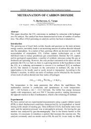
each species in a specific process [8]. The quantified flow diagrams reported in Figure 1 are the<br />
2
Ischia, June, 27-30 - 2010<br />
result <strong>of</strong> the MFA/SFA applied to the main process units (gasifier, cyclone, wet scrubber, water<br />
treatment system) <strong>of</strong> the pilot scale gasification system. Each flow in entrance to or in exit from a<br />
specific unit is identified by means <strong>of</strong> a black arrow if the specific data have been measured or<br />
fixed, or by a grey arrow if the data have been obtained by means <strong>of</strong> MFA/SFA. The layer <strong>of</strong><br />
total mass flow rate is reported in Fig.1A. The input flows to the BFBG unit are the stream <strong>of</strong><br />
biomass fuel, that <strong>of</strong> a small flow rate <strong>of</strong> nitrogen utilized to facilitate the fuel injection and that<br />
<strong>of</strong> air used as reducing agentand fluidizing gas. The output flow stream is the obtained syngas<br />
(14% CO 2 , 17.9% CO, 12.3% H 2 , 3.9% CH 4 , 1.2% C n H m and the rest N 2 ) which still contains<br />
heavy hydrocarbons, inorganic pollutants and entrained fines. The dirty syngas is sent to the<br />
cyclone for dust abatement and then to the wet scrubber for removal <strong>of</strong> tars and inorganic<br />
compounds. The specific production <strong>of</strong> syngas is equal to 2.45kg syngas /kg fuel (i.e.<br />
2.1m 3 N, syngas /kg fuel ) while that <strong>of</strong> elutriated fines is 20.9g fines /kg fuel . The stock <strong>of</strong> 145kg <strong>of</strong> bed<br />
particles is progressively incremented (0.30kg/h) as a result <strong>of</strong> opposite effects <strong>of</strong> elutriation<br />
losses and fuel ash accumulation.<br />
Table 2. Operating Conditions and Output<br />
Process Data<br />
Operating Conditions<br />
ER (equivalence ratio), - 0.28<br />
AF (air/fuel ratio), kg air /kg fuel 1.53<br />
Temperature <strong>of</strong> fluidizing air at gasifier 545<br />
entrance, °C<br />
Output Process Data<br />
Temperature <strong>of</strong> fluidized bed at thermal 880<br />
steady-state,°C<br />
Temperature <strong>of</strong> syngas at gasifier 740<br />
exit,°C<br />
Q syngas, m 3 N/kg fuel 2.1<br />
LHV syngas, kJ/m 3 N 5900<br />
Specific energy , kWh/kg fuel 3.4<br />
CGE (cold gas efficiency) , - 0.77<br />
Entrained carbon fines, g C /kg C-fuel 31.2<br />
PAH, mg/m 3 N 2300<br />
HCl, mg/m 3 N 13<br />
H 2 S, mg/m 3 N 1<br />
NH 3 , mg/m 3 N 16<br />
The experimental activity provides the<br />
complete chemical composition <strong>of</strong> streams<br />
leaving the cyclone and the water treatment<br />
system. These data have been used for the<br />
substance flow analysis <strong>of</strong> carbon [9] and for<br />
the feedstock energy flow analysis (Fig. 1B).<br />
Figure 1B reports the layer <strong>of</strong> feedstock<br />
energy, i.e. the heat <strong>of</strong> combustion <strong>of</strong> each<br />
input and output streams: the energy flow<br />
entering with the biomass fuel has been<br />
determined by means <strong>of</strong> a relationships<br />
recently proposed and validated specifically<br />
for biomass fuels [10], while the energy<br />
flows <strong>of</strong> exit streams have been evaluated on<br />
the basis <strong>of</strong> the heats <strong>of</strong> combustion <strong>of</strong> the<br />
specific substances. The resulting difference<br />
in feedstock energy, 151MJ/h, is that<br />
“invested” at the steady-state condition to<br />
convert the solid biomass in a gaseous fuel.<br />
Reported data allow to evaluate the cold gas<br />
efficiency CGE, defined as the ratio between<br />
the chemical energy <strong>of</strong> obtained syngas and that <strong>of</strong> injected fuel: the value <strong>of</strong> 0.765 is mainly<br />
determined by the chemical energy utilized inside the gasifier (19.5%) and, for a smaller<br />
fraction, by the fraction <strong>of</strong> feedstock energy lost with the entrained fines (3.2%) and with the<br />
heavy hydrocarbons <strong>of</strong> the purge stream from the water treatment system (0.8%). These results<br />
suggest two possible design solutions: the make-up <strong>of</strong> bed olivine particles and the recycle <strong>of</strong><br />
entrained fines. These data were finally combined with relationships <strong>of</strong> fluidization engineering<br />
[11] in order to determine the main geometrical parameters <strong>of</strong> the gasification section.<br />
3
Processes and Technologies for a Sustainable Energy<br />
Figure 1. Layers <strong>of</strong> mass and energy balances throughout the pilot scale gasifier: A) total mass<br />
(kg/h); B) feedstock energy (MJ/h).<br />
The possible devices that can be used in the electricity generation section have been compared<br />
and for each <strong>of</strong> them have been taken in account its advantages and disadvantages when coupled<br />
with a BFB gasifier. The steam turbine and boiler combination has its main positive feature in<br />
insuring that the expanding fluid is completely isolated from the syngas combustion fumes,<br />
therefore avoiding the corrosion, fouling and plugging <strong>of</strong> the rotating parts, but commercially<br />
available steam turbines in the size range considered for this study have an extremely low net<br />
electrical efficiency [10-20%] and additionally require a large condenser if the steam cycle is to<br />
be run in a closed loop configuration [12]. The intensive capital costs and the limited<br />
performance <strong>of</strong> the boiler and steam turbine configuration lead to the exclusion <strong>of</strong> this solution<br />
as a viable one. Another combination that was not further analyzed is that with an internal<br />
combustion gas turbine. Although internal combustion gas turbines <strong>of</strong>fer very good net electric<br />
efficiency across small size ranges, the direct combustion and expansion <strong>of</strong> the syngas and its<br />
fumes into the turbomachinery poses technical difficulties. In fact, decontaminating the syngas <strong>of</strong><br />
particulate, tar, alkali and acids to manufacturer’s specification if <strong>of</strong>ten unfeasible due to<br />
incongruent costs <strong>of</strong> the equipment for the size range <strong>of</strong> the installation. Conversely, designing<br />
for costs can lead to residual contamination that fails to meet manufacturer’s specifications<br />
which can cause unpredictable shortening <strong>of</strong> life or major failures <strong>of</strong> the machinery. Recently a<br />
customization <strong>of</strong> the basic gas turbine machine has been readied for commercialization that<br />
overcomes the main problems associated with internal combustion gas turbines. This<br />
configuration is named either externally-fired gas turbine or hot-air gas turbine, since the<br />
working fluid is ambient air and the heat addition happens in a gas-gas high temperature<br />
exchanger [13]. The separation <strong>of</strong> the working fluid from the combustion fumes assures that the<br />
rotating parts are not deteriorated, fouled or plugged, as for a steam turbine, while the use <strong>of</strong> the<br />
exhaust clean hot air from the turbine outlet as the oxidizing gas in the syngas combustion,<br />
4
Ischia, June, 27-30 - 2010<br />
assures that high thermodynamic efficiencies are achieved. The last solution that has been<br />
investigated is a syngas optimized high efficiency alternating engine. This type <strong>of</strong> engine is a<br />
proven technology that yields high electrical efficiency but has somewhat stringent requirements<br />
on both purity and technical conditions for the syngas supply [14]. In the case <strong>of</strong> the gas engine<br />
setup though, the decontamination <strong>of</strong> the syngas can be achieved with a sufficiently inexpensive<br />
equipment, an aspect that renders the solution viable and competitive. In fact, the engine based<br />
installation is usually regarded as the standard against which other alternatives have to be<br />
compared in terms <strong>of</strong> electrical and economical efficiency.<br />
On the basis <strong>of</strong> the preliminary selection process illustrated above, the cleaning section has been<br />
designed for the two most promising plant configurations. The relative succession <strong>of</strong> the<br />
utilization and cleaning sections depends on the two possible types <strong>of</strong> biomass-to-energy<br />
gasification system that can be adopted: for the gas engine configuration is a tipical “power<br />
gasification” being the producer gas first cleaned then burned, while for that with the gas turbine<br />
it is a “heat gasification” where the syngas is first burned then cleaned [15]. In the first case the<br />
cleaning section (air preheating heat exchanger, dissipator, scrubber, chiller and demister) works<br />
as an interface between the characteristics <strong>of</strong> the producer gas and those required by the specific<br />
generator set. In the second case, downstream <strong>of</strong> the gasifier there is a combustion and heat<br />
recovery section that consists <strong>of</strong> a possible pre-treatment <strong>of</strong> the syngas to remove contaminants<br />
before it goes into the combustor, a high temperature heat exchanger, and, above all, an airpollution<br />
control system for flue gas cleaning.<br />
5. PROCESS PERFORMANCE COMPARISON<br />
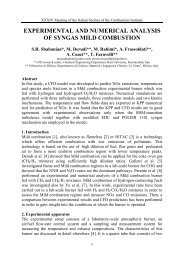
On the basis <strong>of</strong> considerations reported above, the process flow diagrams for the gas engine and<br />
for the externally fired gas turbine plant configurations have been defined (Figure 2). Both are<br />
composed by three sections: the gasification, cleaning and electricity generation. Although the<br />
two alternative configurations are based on the same gasification section, modelled on the basis<br />
<strong>of</strong> experimental data, they nonetheless differ in their energetic and environmental performance,<br />
as simulated on the basis <strong>of</strong> mass and energy balances and <strong>of</strong> the performance data claimed by<br />
manufacturers [16]. Comparing the two plants on the basis on one aspect <strong>of</strong> their performance<br />
alone, e.g. their overall energy conversion efficiency, might be reductive since this would<br />
overlook other equally important aspects <strong>of</strong> the operation <strong>of</strong> power generation systems, such as<br />
their environmental burden and ease <strong>of</strong> conduction. On one hand, the gas engine solution <strong>of</strong>fers<br />
higher global efficiency (about 27%) due to the performance <strong>of</strong> the generator set and a lower<br />
capital cost, but has a generally lower availability and higher maintenance costs [12, 13].<br />
Moreover, it requires a suitable treatment unit for the waste water from the scrubber purge that is<br />
contaminated by tars, particulate and inorganics. On the other hand, the externally-fired gas<br />
turbine solution has a less efficient process (about 23%) due to intrinsic thermodynamic limits<br />
and, for a less extent, to some losses inherent to the heat exchanger steps it embeds and a higher<br />
initial investment costs. The EFGT has a higher annual availability (about 3% more) and must<br />
dispose a solid waste stream (coming from APC unit) instead <strong>of</strong> a liquid one (coming from the<br />
wet scrubber unit), even though the advantage <strong>of</strong> the lack <strong>of</strong> an onerous water treatment system<br />
is balanced by the disadvantage <strong>of</strong> a very larger mass <strong>of</strong> flue gases to be treated at the stack.<br />
Moreover, the EFGT configuration has a lower specific biomass conversion rate, which results in<br />
a larger fuel feed rates, even though it can <strong>of</strong>fer a more cogenerative capability, which is related<br />
to the higher temperature <strong>of</strong> the stack gas (313°C instead 145°C).<br />
5
Figure 2. The process flow diagrams for the gas engine (A) and the externally fired gas turbine (B) configurations.<br />
6
REFERENCES<br />
1. A. Dermibas, <strong>Biomass</strong> resource facilities and biomass conversion processing for fuels and<br />
chemicals, Energy Conv. And Manag., 42 (2001)1357-1378.<br />
2. L. Wang, C.L. Weller, D.D. Jones, M.H. Hanna, Contemporary issues in thermal<br />
gasification <strong>of</strong> biomass and its application to electricity and fuel production, <strong>Biomass</strong> and<br />
Bioenergy, 32 (2008) 573-581.<br />
3. M. Baratieri, P. Baggio, L. Fiori, M. Grigiante, <strong>Biomass</strong> as an energy source:<br />
Thermodynamic constraints on the performance <strong>of</strong> the conversion process, Bioresource<br />
Techn., 99 (2008) 7063-7073.<br />
4. H.A.M. Knoef (ed.), Handbook <strong>of</strong> <strong>Biomass</strong> <strong>Gasification</strong>, BTG-<strong>Biomass</strong> Technology Group<br />
(ISBN 90-810068-1-9), The Netherlands, 2005.<br />
5. U. Arena, L. Zaccariello, M.L. Mastellone, <strong>Gasification</strong> <strong>of</strong> natural and waste biomass in a<br />
pilot scale fluidized bed reactor, Combust. Sci. and Tech., 182 (2010) 1–15.<br />
6. F. Miccio, B. Piriou, G. Ruoppolo, R. Chirone, <strong>Biomass</strong> gasification in a catalytic fluidized<br />
reactor with beds <strong>of</strong> different materials, Chem. Eng. J., 154 (2009) 369-274.<br />
7. U. Arena, E. Romeo, M.L. Mastellone, Recursive Operability Analysis <strong>of</strong> a Pilot Plant<br />
Gasifier, J. Loss Prev. in the Proc. Ind., 21/1 (2008) 50-65.<br />
8. P.H. Brunner and H. Rechberger, Practical Handbook <strong>of</strong> Material Flow Analysis. CRC<br />
Press LLC, Boca Raton, FL, 2004.<br />
9. U. Arena, F. Di Gregorio, L. Zaccariello, M.L. Mastellone, <strong>Fluidized</strong> <strong>Bed</strong> <strong>Gasification</strong> <strong>of</strong><br />
<strong>Biomass</strong>: A Substance Flow Analysis. Fluidization XIII - New paradigm in fluidization<br />
engineering, Korea (2010) 805-812.<br />
10. C. Sheng and J.L.T. Azevedo, Estimating the higher heating value <strong>of</strong> biomass fuels from<br />
basic analysis data, <strong>Biomass</strong> and Bioenergy, 28 (2005) 499–507.<br />
11. D. Kunii and O. Levenspiel, Fluidization Engineering. 2nd ed., Butterworth-Heinemann,<br />
London, 1991.<br />
12. A.V. Bridgewater, The technical and economic feasibility <strong>of</strong> biomass gasification for power<br />
generation, Fuel, 47/5 (1995) 631-633.<br />
13. D. Cocco, P. Deiana, G. Cau, Performance evaluation <strong>of</strong> small size externally fired gas<br />
turbine (EFGT) power plants integrated with direct biomass dryers, Energy, 31/10-11<br />
(2006) 1459-1471.<br />
14. A.L. Boehman and O. Le Corre, Combustion <strong>of</strong> syngas in internal combustion engines,<br />
Combustion Sci. and Tech., 180/6 (2008) 1193-1206.<br />
15. C. Heermann, F. J. Schwager, K. J. Whiting, Pyrolysis & <strong>Gasification</strong> <strong>of</strong> Waste. A<br />
Worldwide Technology & Business Review. 2nd Edition. Juniper Consultancy Services<br />
Ltd, 2001.<br />
16. U. Arena, F. Di Gregorio, M. Santonastasi, A Techno-Economic Comparison Between Two<br />
Design Configurations for a Small Scale, <strong>Biomass</strong>-to-Energy <strong>Gasification</strong> Based System,<br />
Chem. Eng. Journal, in press (2010).<br />
7