GRUNFOS FIRE SYSYTEMS O & M MANUALS - Xact
GRUNFOS FIRE SYSYTEMS O & M MANUALS - Xact
GRUNFOS FIRE SYSYTEMS O & M MANUALS - Xact

Create successful ePaper yourself
Turn your PDF publications into a flip-book with our unique Google optimized e-Paper software.
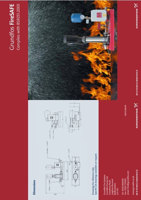
Dimensions<br />
Drawings for reference only.<br />
Specific GA drawings available on request.<br />
Grundfos Fire Systems<br />
Grundfos Pumps Ltd<br />
Grovebury Road<br />
Leighton Buzzard<br />
Bedfordshire.<br />
LU7 4TL<br />
Tel: 01525 850000<br />
Fax: 01525 775300<br />
email: fire@grundfos.com<br />
www.grundfos.co.uk<br />
GB/FS/08/05<br />
Grundfos FireSAFE<br />
Complies with BS9251:2005
Outline<br />
In Britain each year there are over 60,000<br />
domestic & residential fires which are responsible<br />
for at least 600 deaths and 10, 000 serious injuries.<br />
As a result, there has been a growing awareness<br />
in the UK market of the virtues of a correctly<br />
designed and installed sprinkler system to detect<br />
and control a fire at an early stage, thus providing<br />
a cost effective safeguard against loss of life and<br />
property in such dwellings.<br />
The Grundfos FireSAFE (Safe Active Fire Equipment)<br />
range of pump packages is designed to comply with<br />
the recommendations of draft British Standard,<br />
BS9251:2005.<br />
In some situations, and with the permission of the<br />
Water Utility, it may be possible to connect the<br />
Grundfos FireSAFE set directly to the town water<br />
mains. A dedicated suction pipe will be required, the<br />
diameter of which should match the pump suction as<br />
an absolute minimum.<br />
In situations where the town mains supply cannot be<br />
utilised directly it will be necessary to install a water<br />
storage (break) tank between the mains and the<br />
Grundfos FireSAFE set. Grundfos can offer a suitable<br />
break tank.<br />
The Grundfos FireSAFE supplies water via a riser<br />
system within the building to a series of sprinkler<br />
heads. When the air temperature around a sprinkler<br />
head reaches a predetermined level, the glass bulb<br />
bursts, leading to a loss of system pressure and/or a<br />
water flow. This is detected by a pressure switch or a<br />
flow switch integral to the Grundfos Fire SAFE set,<br />
so activating the pump. Only sprinkler heads affected<br />
directly by the heat source will operate.<br />
Specification Details<br />
Pump Type - Grundfos Horizontal or Vertical<br />
Multistage - sized according to individual<br />
system flow / pressure requirements.<br />
Electrical Supply - 240/1/50 or 400/3/50<br />
The pump unit is supplied on a powder-coated<br />
base, pre-wired and tested with all equipment<br />
needed for automatic operation and also<br />
includes the components normally found in<br />
a proprietary riser assembly.<br />
Key Features<br />
8 Litre Accumulator<br />
Maintains system pressure against minor leakage and allows for<br />
thermal expansion caused by ambient temperature variations.<br />
A pressure relief valve, which is sometimes fitted on riser assemblies,<br />
is therefore not considered necessary.<br />
Dual Pressure Switches for pump control<br />
This assembly allows the pump unit to operate both as a Jockey<br />
pump, and a duty pump. Therefore, if the first pressure switch is<br />
activated, and a flow detected, a volt free contact is activated<br />
connected to a central monitoring / alarm panel.<br />
When the system pressure is restored AND a no flow condition is<br />
detected, the pump will stop and this signal will cease. Should the<br />
second pressure switch be activated, indicative of sprinkler activation,<br />
the set will run until stopped manually.<br />
Flow Switch for integration into the Alarm system<br />
Used in conjunction with pressure switches in order to activate<br />
pump unit via control panel.<br />
Pressure gauge<br />
Fitted next to accumulator to provide visual indication of<br />
system pressure.<br />
Test/Drain point<br />
Drainage point located on main manifold that allows the sprinkler<br />
system to be drained. Also allows for testing of flow meter (and<br />
alarm signal).<br />
Control panel with all functions needed for Automatic operation<br />
The control panel has been specifically designed by Grundfos to<br />
conform with BS9251: 2005. The panel will initiate the pump<br />
upon receipt of a signal from the pressure switch. It will also run<br />
the pump once a month for a few seconds at a time in order to<br />
lubricate the shaft seal and top up the hydraulic accumulator,<br />
thus making the system maintenance-free. There is a manual<br />
TEST button that allows pump rotation at any time without<br />
activating the alarm VFC.<br />
The control panel is fail-safe, so any loss in power will result<br />
in an alarm signal being sent to the alarm panel.<br />
Manual shut off switch for use after full activation<br />
This switch is located on the control panel and will<br />
shut down the pump as required by BS9251: 2005.