V92TC V92TC DELUXE - Polaris
V92TC V92TC DELUXE - Polaris
V92TC V92TC DELUXE - Polaris

Create successful ePaper yourself
Turn your PDF publications into a flip-book with our unique Google optimized e-Paper software.
2002<br />
<strong>V92TC</strong><br />
<strong>V92TC</strong> <strong>DELUXE</strong>
WARNING<br />
The engine exhaust from this<br />
product contains chemicals known<br />
to cause cancer, birth defects or<br />
other reproductive harm.
We’ve created a web site, just for YOU!!<br />
S Technical tips<br />
S New product introductions<br />
S Event schedules<br />
S Parts and Service Manual information<br />
S Exciting details about The Way Out<br />
Check it out...<br />
www.polarisindustries.com
All text, photographs, and illustrations in this manual are based on the most current product information available<br />
at the time of publication. Product improvements or other changes may result in differences between this manual<br />
and the motorcycle. <strong>Polaris</strong> Industries reserves the right to make production changes at any time, without notice<br />
and without incurring any obligation to make the same or similar changes to motorcycles previously built.<br />
2002 OWNER’S MANUAL<br />
<strong>V92TC</strong>/<strong>V92TC</strong> Deluxe<br />
Victory Motorcycle Division, <strong>Polaris</strong> Industries Inc.<br />
2100 Highway 55, Hamel, Minnesota 55340-9800 Tele: (763) 542-0500 Fax: (763) 542-0599<br />
CopyrightE 2001 <strong>Polaris</strong> Industries Inc. All rights reserved.<br />
Victory Motorcycles is a registered trademark of <strong>Polaris</strong> Industries Inc.<br />
Dunlop is a registered trademark of Dunlop Tire Corporation.<br />
Features of Victory motorcycles are covered by U.S. Patent Nos. D397976, D398065, D407169,<br />
D409551, D416831, D436561, with additional patents pending.
Foreword<br />
Thank you for choosing a Victory Motorcycle!<br />
The Owner’s Manual contains information on the following Victory Motorcycles:<br />
<strong>V92TC</strong> Touring Cruiser<br />
<strong>V92TC</strong> Deluxe Touring Cruiser<br />
All photographs and illustrations used are generalizations, and your specific model may be slightly different<br />
than what is shown.<br />
If you misplace or damage the Owner’s Manual, you should purchase a replacement copy from an authorized<br />
Victory dealer. The manual should be considered part of the motorcycle, and remain with the motorcycle<br />
when it is sold.<br />
If after reading the Owner’s Manual you have questions about the operation or maintenance of the<br />
motorcycle, contact an authorized Victory dealer. To locate an authorized Victory dealer near you:<br />
Call 1 -800 -POLARIS and provide the area code or zip code of your location.<br />
Visit www.polarisindustries.com for a listing of authorized Victory dealers by state, zip code, or area<br />
code.<br />
i
Foreword<br />
Your authorized Victory dealer will resolve all issues regarding the motorcycle. If you are unsatisfied with the<br />
performance of your Victory dealer, contact <strong>Polaris</strong> Customer Service at 763 -417 -8650.<br />
Victory motorcycles comply with all federal, state, and local safety and emission regulations for the area of<br />
intended sale.<br />
Have a safe and enjoyable ride.<br />
ii
Table of Contents<br />
Introduction ..................... 1<br />
Read the Owner’s Manual .............. 1<br />
Symbols and Terms Used in the Owner’s<br />
Manual ............................... 2<br />
Safety Precautions ............... 3<br />
Safe Riding ........................... 4<br />
Design Characteristics ................. 4<br />
Safe Riding Practices ................. 5<br />
Carrying a Passenger ................. 8<br />
Protective Apparel ..................... 9<br />
Gross Vehicle Weight Rating (GVWR) ... 10<br />
Loading .............................. 12<br />
Saddlebags ........................... 13<br />
Parking ............................... 14<br />
Transporting .......................... 14<br />
Product Modifications ................. 15<br />
Selecting and Installing Accessories ... 15<br />
Gasoline and Exhaust Gases ........... 16<br />
Maintenance .......................... 17<br />
Location of Safety and Vehicle<br />
Information Labels .................... 19<br />
Reporting Safety Defects .............. 22<br />
Motorcycle Description ........... 23<br />
Vehicle Identification Number .......... 27<br />
Engine Identification Number .......... 27<br />
Ignition Key Number ................... 28<br />
Instruments and Controls ........ 29<br />
Ignition Key ........................... 29<br />
Steering Lock ......................... 29<br />
Ignition Switch ........................ 30<br />
Off Position .......................... 30<br />
On Position .......................... 30<br />
P (Park) Position ..................... 31<br />
Instrument Cluster .................... 31<br />
Speedometer ......................... 31<br />
Tachometer .......................... 31<br />
Indicator Lights ....................... 32<br />
Low Oil Pressure Indicator ............. 32<br />
Low Fuel Indicator .................... 32<br />
Neutral Indicator ...................... 32<br />
Turn Signal Indicators ................. 32<br />
iii
Table of Contents<br />
Headlamp High Beam Indicator ......... 33<br />
Multi -Function Display (MFD) .......... 33<br />
Odometer ............................ 33<br />
Trip Odometer ........................ 33<br />
Clock ............................... 34<br />
Instrument Cluster Light Dimmer ........ 35<br />
Headlamp High Beam Indicator Light<br />
Dimmer ............................. 35<br />
Fuel Gauge .......................... 35<br />
Voltmeter ............................ 35<br />
Check Engine Indicator ................ 36<br />
Left Side Handlebar Controls ........... 38<br />
Fast Idle Lever ....................... 38<br />
Headlamp High/Low Beam Switch ...... 38<br />
Turn Signal Switch .................... 38<br />
Horn Button .......................... 38<br />
Clutch Lever ......................... 39<br />
Multi--Function Display (MFD) Set<br />
Button ............................... 39<br />
Right Side Handlebar Controls ......... 39<br />
Engine Stop/Run Switch ............... 39<br />
Emergency Flasher Switch ............. 40<br />
Starter Button ........................ 40<br />
Front Brake Lever .................... 40<br />
iv<br />
Throttle Control Grip .................. 40<br />
Multi--Function Display (MFD) Mode<br />
Button ............................... 40<br />
Gear Shift Pedal ....................... 41<br />
Rear Brake Pedal ...................... 41<br />
Fuel Cap .............................. 41<br />
Auxiliary Light Switch ................. 42<br />
Saddlebags ........................... 42<br />
Side Covers ........................... 43<br />
Sidestand ............................. 43<br />
Pre-Operation Check ............. 45<br />
Check Electrical Equipment ............ 45<br />
Instrument Cluster .................... 45<br />
Headlamp ........................... 46<br />
Taillight .............................. 46<br />
Turn Signals/Running Lights ............ 46<br />
Emergency Flashers .................. 46<br />
Horn ................................ 46<br />
Engine Stop/Run Switch ............... 47<br />
Check Engine Oil Level ................ 47<br />
Fuel .................................. 48<br />
Check Fuel Level ..................... 48<br />
Check Fuel Hose, Rail, and<br />
Connections ......................... 48
Table of Contents<br />
Check Evaporative Emission Control<br />
System (California model only) ......... 48<br />
Tires ................................. 49<br />
Check Tire Pressure .................. 49<br />
Tire Pressure Table ................... 49<br />
Check Tire Condition .................. 50<br />
Check Tread Depth ................... 50<br />
Brakes ................................ 50<br />
Check Front Brake Lever Movement .... 50<br />
Check Front Brake Fluid Level .......... 51<br />
Check Rear Brake Pedal Freeplay and<br />
Movement ........................... 51<br />
Check Rear Brake Fluid Level .......... 52<br />
Check Hoses and Connections ......... 52<br />
Check Brake Pads .................... 52<br />
Check Throttle Control Grip and<br />
Cables ................................ 53<br />
Check Clutch ......................... 53<br />
Check Fast Idle Lever .................. 54<br />
Check Front Suspension ............... 54<br />
Check Steering ........................ 55<br />
Check Rear Suspension ............... 55<br />
Check Drive Belt ...................... 55<br />
Check Sidestand ...................... 56<br />
Check Fasteners ...................... 56<br />
Operation ....................... 57<br />
Engine Break -in Period ................ 57<br />
Fueling and Fill Height ................. 59<br />
Starting the Engine .................... 60<br />
Shifting Gears ........................ 62<br />
Accelerating .......................... 65<br />
Braking ............................... 66<br />
Stopping the Engine ................... 67<br />
Parking ............................... 67<br />
Maintenance ..................... 69<br />
Initial Maintenance .................... 70<br />
Periodic Maintenance Intervals ......... 70<br />
Periodic Maintenance Interval Table ..... 71<br />
Engine Oil ............................ 74<br />
Change Engine Oil and Oil Filter ........ 74<br />
Check Engine Oil Level ................ 75<br />
Inspect Air Filter ...................... 76<br />
Inspect Drive Sprocket and Sprocket<br />
Nut ................................... 77<br />
Drive Belt ............................. 77<br />
Check Drive Belt Condition ............. 77<br />
v
Table of Contents<br />
Check Drive Belt Tension .............. 78<br />
Adjust Drive Belt Tension .............. 79<br />
Align Rear Wheel ..................... 80<br />
Rear Suspension ...................... 82<br />
Adjust Rear Shock Absorber ........... 82<br />
Inspect Swing Arm and Rear Axle ....... 84<br />
Front Suspension and Steering ........ 85<br />
Check Front Forks .................... 85<br />
Replace Front Fork Oil ................ 85<br />
Inspect Steering and Front Axle ......... 86<br />
Fuel System .......................... 87<br />
Check Fuel Hose, Rail, and<br />
Connections ......................... 87<br />
Check Crankcase Ventilation Hose and<br />
Connections ......................... 87<br />
Evaporative Emission Control System<br />
(California models only) ................ 87<br />
Fuel Tank ............................ 87<br />
Replace Fuel Filter .................... 88<br />
Fast Idle Lever ........................ 88<br />
Check Fast Idle Lever and Cable ....... 88<br />
Adjust Fast Idle Lever Freeplay ......... 88<br />
Throttle ............................... 89<br />
Check Throttle Control Grip and Cable ... 89<br />
vi<br />
Adjust Throttle Freeplay ............... 89<br />
Clutch ................................ 90<br />
Check Clutch Lever and Cable .......... 90<br />
Lubricate Clutch Lever ................. 90<br />
Adjust Clutch Freeplay ................ 91<br />
Lubricate Control Cables .............. 92<br />
Brakes ................................ 92<br />
Check Front Brake Lever Movement .... 92<br />
Lubricate Front Brake Lever ............ 93<br />
Check Front Brake Fluid Level .......... 93<br />
Add Front Brake Fluid ................. 93<br />
Check Rear Brake Pedal Freeplay and<br />
Movement ........................... 95<br />
Adjust Rear Brake Pedal Freeplay ...... 95<br />
Check Rear Brake Fluid Level .......... 96<br />
Add Rear Brake Fluid ................. 96<br />
Check Brake Pads .................... 97<br />
Check Brake Hoses and Connections ... 98<br />
Gear Shift Pedal ....................... 98<br />
Adjust Gear Shift Pedal Height ......... 98<br />
Tires ................................. 99<br />
Check Tire Pressure .................. 99<br />
Tire Pressure Table ................... 99<br />
Check Tire Condition .................. 100<br />
Check Tread Depth ................... 100
Table of Contents<br />
Check Wheel Spokes .................. 100<br />
Check or Replace Spark Plugs ......... 101<br />
Check Engine Compression ............ 103<br />
Check Exhaust System ................ 103<br />
Remove and Install Seat ............... 104<br />
Battery ............................... 105<br />
Remove Battery ...................... 106<br />
Charge Battery ....................... 106<br />
Install Battery ........................ 107<br />
Electrical Equipment .................. 108<br />
Replace Fuses ....................... 108<br />
Adjust Headlamp ..................... 109<br />
Adjust Auxiliary Lights ................. 110<br />
Remove and Install Saddlebags ........ 111<br />
Sidestand ............................. 111<br />
Lubricate Sidestand ................... 111<br />
Inspect Sidestand Pad ................. 112<br />
Check Fasteners ...................... 113<br />
Road Test ............................. 113<br />
Cleaning and Storage ............ 115<br />
Cleaning .............................. 115<br />
Washing and Drying ................... 116<br />
Waxing, Polishing, and Applying<br />
Protectants (Items Other Than<br />
Windshields) ......................... 118<br />
Windshield Care ...................... 119<br />
Repairing Painted Surface Damage ..... 119<br />
Storage ............................... 120<br />
Preparing for Storage ................. 120<br />
Clean and Protect the Motorcycle ....... 120<br />
Stabilize Fuel ......................... 121<br />
Protect Engine Components ............ 121<br />
Inflate Tires .......................... 122<br />
Remove, Clean, and Store Battery ...... 122<br />
Park and Cover the Motorcycle ......... 122<br />
Maintaining During Storage ............ 123<br />
Removing from Storage ............... 123<br />
Warranties ....................... 125<br />
Motorcycle Noise Regulation ........... 125<br />
Noise Emission Warranty .............. 126<br />
Emissions Control System Warranty .... 126<br />
Your Warranty Rights and Obligations ... 126<br />
Manufacturer’s Warranty Coverage ...... 127<br />
Owner’s Warranty Responsibilities ...... 127<br />
I. Coverage .......................... 128<br />
II. Limitations ......................... 129<br />
vii
Table of Contents<br />
III. Limited Liability .................... 130<br />
IV. Legal Rights ....................... 131<br />
V. This Warranty Is In Addition To The<br />
Victory Limited Motorcycle Warranty. .... 131<br />
VI. Additional Information. .............. 131<br />
Victory Motorcycle Warranty Policy ..... 132<br />
Limited Warranty ..................... 132<br />
Registration .......................... 132<br />
Warranty Coverage And Exclusions: ..... 133<br />
Specifications ................... 135<br />
Fuel Specifications .................... 139<br />
Engine Oil Specifications .............. 139<br />
Identification Numbers for Your<br />
Motorcycle ............................ 140<br />
Index ............................ 141<br />
viii
Introduction<br />
Read the Owner’s Manual<br />
The Owner’s Manual contains information that is essential to safe riding and proper maintenance of all 2002<br />
Victory motorcycles. Anyone who uses the motorcycle (Operators and Passengers) must read the Owner’s<br />
Manual before riding. Carefully read and understand the information found in the ”Safety Precautions”<br />
section. Understand and follow the procedures in the Owner’s Manual to keep your Victory motorcycle in top<br />
condition on the road or in storage. If possible, bring the manual with you when you ride. Failure to follow<br />
the safety precautions and operation and maintenance procedures may result in death or injury to you<br />
or your passenger, or damage to your motorcycle. Following the precautions and procedures in this manual<br />
will add to your enjoyment, and keep you riding safely.<br />
1
Introduction<br />
Symbols and Terms Used in the Owner’s Manual<br />
The following signal words and symbols appear in the Owner’s Manual. Your safety, and the safety of others<br />
are involved when these words and symbols are used. Become familiar with their meanings before reading the<br />
Owner’s Manual.<br />
! The safety alert symbol indicates a potential for personal injury to you or others.<br />
WARNING<br />
Indicates a potential hazard that could result in serious injury or death.<br />
Caution<br />
Indicates a potential hazard that may result in minor personal injury or damage to the motorcycle.<br />
Caution<br />
Indicates a situation that may result in damage to the motorcycle.<br />
Notice<br />
Highlights important information that we don’t want you to overlook.<br />
2
Safety Precautions<br />
WARNING<br />
Improper use of this motorcycle can result in serious injury or death. To minimize the risk of<br />
injury to you, your passenger, and others, read and understand the information contained in this<br />
section before operating the motorcycle. This section contains safety information specific to the<br />
<strong>Polaris</strong> Victory, as well as information about general motorcycle safety. Anyone who uses the<br />
motorcycle (Operators and Passengers) must follow these safety precautions.<br />
Motorcycling has inherent risks. You can minimize those risks, but you can’t eliminate them completely. Take<br />
the time to read and understand the following information to help minimize risk and maximize pleasure when<br />
operating the motorcycle. Even if you are an experienced motorcycle operator or passenger, read this section<br />
of the Owner’s Manual before operating the motorcycle.<br />
S Your ability to safely operate the motorcycle depends on your judgment and use of safe riding habits.<br />
Take a rider education course from the Motorcycle Safety Foundation or another qualified instructor. The<br />
course will help you develop or refresh your expertise in safe riding habits through instruction and riding.<br />
For information on Motorcycle Safety Foundation rider education courses in your area, call<br />
1 -800 -446 -9227 or visit their homepage at http://msf -usa.org.<br />
S Read and understand the rest of the Owner’s Manual. The Manual contains safety information specific to<br />
individual components and operations throughout.<br />
3
Safety Precautions<br />
S Pay close attention to the motorcycle maintenance requirements in this Manual. For additional<br />
information or assistance regarding technical service specified in the Owner’s Manual or required by<br />
mechanical circumstances, see the Victory Service Manual or your authorized Victory Dealer.<br />
Safe Riding<br />
Design Characteristics<br />
The following design characteristics affect how you should ride the Victory motorcycle:<br />
S The motorcycle is designed for on -road use with one rider and one passenger. Do not exceed the gross<br />
vehicle weight rating (see Specifications or the certification label on the steering head). Riding off -road,<br />
riding with more than one passenger, or carrying weight exceeding the maximum weight rating can make<br />
handling difficult, which could cause you to lose control of the motorcycle.<br />
S In the first 500 miles, operate the motorcycle according to the break -in procedures described in “Engine<br />
Break -in” on page 57. Operating the motorcycle without following break -in procedures can result in<br />
serious engine damage.<br />
S Some Victory motorcycles include saddlebags, auxiliary lights, a windshield, a passenger backrest, and a<br />
highway bar as standard equipment. Under certain conditions it may be necessary to reduce the operating<br />
speed of motorcycles with this equipment.<br />
4
Safe Riding Practices<br />
Follow these general safe riding practices:<br />
Safety Precautions<br />
S Before you ride, make sure you can operate the motorcycle safely and properly by following the<br />
recommendations given at the beginning of the Safety Precautions section on page 3.<br />
S Each time you ride, make the checks described in the Pre -Operation Check section. Operating the<br />
motorcycle without completing the pre -operation check can cause damage to the motorcycle or result in<br />
an accident.<br />
S Until you are thoroughly familiar with the Victory motorcycle and all of its controls, practice riding<br />
where there is little or no traffic. Practice riding at moderate speed on varying road surfaces and under<br />
varying weather conditions.<br />
S Know your skills and limits, and ride within them.<br />
S Allow only licensed, experienced operators to ride your motorcycle, and then only after they have<br />
become familiar with its controls and operation.<br />
S Do not ride when you are fatigued or under the influence of alcohol, prescription drugs, over -the -counter<br />
drugs, or any other drugs. Fatigue, alcohol, and drugs can cause drowsiness, loss of coordination, loss of<br />
balance, and can affect your awareness and judgment.<br />
S If your motorcycle operates abnormally, correct the problem immediately (see the Victory Service Manual<br />
or contact your authorized Victory Dealer). If you continue to operate the motorcycle in this condition,<br />
you are likely to aggravate the initial problem, increase the cost of repairs, and threaten your safety.<br />
5
Safety Precautions<br />
Safe Riding Practices (continued)<br />
S The most common cause of accidents involving a motorcycle and an automobile is the automobile<br />
driver’s failure to see the motorcycle. Ride defensively, as if you are invisible to other motorists, even in<br />
broad daylight. Ride where you are visible to other motorists and observe their behavior carefully, as they<br />
may not see or be aware of you.<br />
S Be especially cautious at an intersection, as this is the most likely place for an accident. Remember<br />
that you are more vulnerable to injury on a motorcycle than in an enclosed vehicle.<br />
S To prevent loss of control while operating the motorcycle, keep your hands on the handlebars and your<br />
feet on the footrests.<br />
S Obey the speed limit and adjust your speed and riding technique based on road, weather, and traffic<br />
conditions. As you travel faster, the influence of all other conditions increases, which can lessen the<br />
motorcycle’s stability and increase the possibility of your losing control of the motorcycle.<br />
S Do not move or operate the motorcycle with the steering locked, as steering is severely restricted and you<br />
could drop or lose control of the motorcycle.<br />
S If in doubt, reduce your speed when:<br />
- The road has potholes or is otherwise rough or uneven.<br />
- The road has sand, dirt, gravel or other loose substances on it.<br />
- The road is wet, icy, or oily.<br />
- The road contains painted surfaces, manhole covers, metal grating, railway crossings, or other<br />
slippery surfaces.<br />
6
Safety Precautions<br />
Safe Riding Practices (continued)<br />
S If in doubt, reduce your speed when:<br />
- The weather is windy, raining, or otherwise causing slippery or rapidly changing conditions.<br />
- The traffic is heavy, congested, not allowing sufficient space between vehicles, or otherwise not<br />
flowing smoothly.<br />
- You are being passed in either direction by a large vehicle that produces a wind blast in its wake.<br />
S To maximize braking effectiveness, use the front and rear brakes together. Be aware of the following<br />
braking facts and practices:<br />
- The rear brake provides 40% of the motorcycle’s stopping power, at most.<br />
- Consider road conditions before applying the brakes; when the road is wet, rough, or contains loose<br />
or other slippery substances, apply the brakes gradually.<br />
- Bring the motorcycle to the upright position before applying the brakes, and avoid applying the<br />
brakes in a corner if at all possible. When the motorcycle is leaning through a corner, the amount of<br />
traction available for braking is reduced, increasing the possibility of the tires skidding when you<br />
apply the brakes.<br />
- Improper braking may cause you to lose control of the motorcycle or may not slow you in time to<br />
avoid a collision.<br />
S As you approach a curve, choose a speed and a lean angle that allow you to pass through the curve in<br />
your own lane without applying the brakes. Excessive speed, improper lean angle, or braking in a curve<br />
can cause you to lose control of the motorcycle.<br />
7
Safety Precautions<br />
Safe Riding Practices (continued)<br />
S Ground clearance is reduced when you lean the motorcycle. Do not allow components to contact the road<br />
surface when leaning the motorcycle in a curve, as this could cause you to lose control of the motorcycle.<br />
S Retract the sidestand fully before riding. If the sidestand is not fully retracted while you are riding, it<br />
could contact the road surface and cause you to lose control of the motorcycle.<br />
S Do not tow a trailer. Towing a trailer can make the motorcycle hard to handle and cause you to lose<br />
control of the motorcycle.<br />
Carrying a Passenger<br />
To carry a passenger safely, do the following:<br />
S Direct the passenger to hold onto you, or the seat strap, with both hands and to keep both feet on the<br />
passenger footrests. Do not carry a passenger who cannot place both feet firmly on the passenger<br />
footrests. A passenger who is not holding on properly or who cannot reach the passenger footrests can<br />
shift their body erratically, which can make the motorcycle hard to handle and cause you to lose control<br />
of the motorcycle.<br />
S If necessary, adjust the rear shock absorber preload according to the instructions in “Rear Shock Absorber<br />
Adjustment” page 82. Improper preload adjustment can make your motorcycle hard to handle and cause<br />
you to lose control of the motorcycle.<br />
S Before you ride, be sure your passenger knows safe riding procedures. Discuss any safety information<br />
unfamiliar to your passenger. A passenger who is unaware of safe riding procedures may distract you or<br />
make movements that make the motorcycle hard to handle and cause you to lose control of the<br />
motorcycle.<br />
8
Safety Precautions<br />
Carrying a Passenger (continued)<br />
S Adjust your riding style to compensate for the differences in handling, acceleration, and braking caused<br />
by the additional weight of the passenger. Failure to do so can cause you to lose control of the<br />
motorcycle.<br />
Protective Apparel<br />
To decrease the risk of injury and increase riding comfort, wear the following:<br />
S Wear a Department of Transportation (DOT) or SNELL approved helmet. Some state laws require that<br />
you wear an approved helmet. In accidents involving motorcycles, head injuries are the leading cause<br />
of motorcyclist fatalities, and statistics prove that an approved helmet is the most effective<br />
protection in preventing or reducing head injuries.<br />
S Wear eye protection. Some state laws require that you wear eye protection. Eye protection reduces the<br />
chance that your vision could be impaired by wind or by airborne particles and objects.<br />
S You and your passenger should wear bright or light colored and/or reflective clothing to improve your<br />
visibility to other motorists. A motorist’s failure to see or recognize a motorcycle is the leading cause<br />
of automobile/motorcycle accidents.<br />
S Wear gloves and a jacket to prevent or reduce abrasions, lacerations, or burns that you can suffer if you<br />
fall.<br />
9
Safety Precautions<br />
Protective Apparel (continued)<br />
S Wear heavy boots and pants to prevent or reduce abrasions, lacerations, or burns that you can suffer if you<br />
fall. Wear boots with low heels because boots with high heels can catch on pedals or footrests. The<br />
combination of your boots and pants should completely cover your legs, ankles, and feet, protecting you<br />
from engine and exhaust system heat. The engine and exhaust system get hot soon after the engine is<br />
started, and stay hot for about half an hour after the engine is turned off.<br />
S Do not wear loose, flowing clothing or long boot laces, as they can catch on components like handlebars,<br />
levers, or footrests, or get caught in the wheels, causing you to lose control of the motorcycle.<br />
Gross Vehicle Weight Rating (GVWR)<br />
Gross vehicle weight is the total weight of the motorcycle, the operator, and the passenger.<br />
S The weight of the motorcycle includes: the motorcycle and all its fluids; any accessories and their<br />
contents; and any additional cargo on the motorcycle.<br />
S The weight of the operator or passenger includes: body weight, all apparel, and objects in or on apparel.<br />
Do not exceed the motorcycle’s gross vehicle weight rating. Exceeding the weight rating can reduce stability<br />
and handling and could cause you to lose control of the motorcycle.<br />
For the gross vehicle weight rating of your specific Victory model, see Specifications or the certification label<br />
on the steering head.<br />
10
Safety Precautions<br />
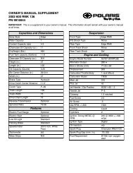
Example 1: <strong>V92TC</strong> Touring Cruiser with no cargo<br />
Gross Vehicle Weight Rating 1210 lbs (549 kg)<br />
Item<br />
Touring Cruiser - with full capacity of all fluids<br />
Operator - with recommended riding apparel<br />
Passenger - with recommended riding apparel<br />
Total Weight<br />
Weight<br />
759 lbs (344 kg)<br />
220 lbs (100 kg)<br />
155 lbs (70 kg)<br />
1134 lbs (514 kg)<br />
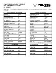
Example 2: <strong>V92TC</strong> Deluxe Touring Cruiser with cargo<br />
Gross Vehicle Weight Rating 1210 lbs (549 kg)<br />
Item<br />
Deluxe Touring Cruiser - with full capacity of all fluids<br />
Cargo - saddlebags at capacity<br />
Operator - with recommended riding apparel<br />
Passenger - with recommended riding apparel<br />
Total Weight<br />
Weight<br />
770 lbs (349 kg)<br />
30 lbs (13.6 kg)<br />
220 lbs (100 kg)<br />
155 lbs (70 kg)<br />
1175 lbs (533 kg)<br />
11
Safety Precautions<br />
Loading<br />
Use the following guidelines when attaching cargo or accessories to the motorcycle. Where applicable, these<br />
guidelines refer to accessories and their contents.<br />
S Keep cargo and accessory weight to a minimum, and keep it as close to the motorcycle as possible, to<br />
minimize a change in the motorcycle’s center of gravity. Changing the center of gravity can lessen<br />
stability and handling and could cause you to lose control of the motorcycle.<br />
S Distribute weight evenly on both sides of the motorcycle. Maintain even weight distribution by checking<br />
accessories and cargo to make sure they are securely attached to the motorcycle before riding and<br />
whenever you take a break while riding. Uneven weight distribution, or accessories or cargo that shift<br />
suddenly while you are riding, can make the motorcycle hard to handle and cause you to lose control of<br />
the motorcycle.<br />
S Do not attach large or heavy cargo such as sleeping bags, duffle bags, or tents to the handlebars, front fork<br />
area, or front fender. If you add accessories to the handlebars or the front fork area, they must be as small<br />
and as lightweight as possible. Cargo or accessories placed in any of these areas can cause instability due<br />
to improper weight distribution or aerodynamic changes, and can cause you to lose control of the<br />
motorcycle. Such items can also block airflow to the engine and could cause overheating that can damage<br />
the engine.<br />
S Do not exceed the maximum cargo weight limit of any accessory (see accessory instructions and labels),<br />
and do not attach cargo to an accessory not designed for that purpose, as either of these could result in an<br />
accessory failure that could cause you to lose control of the motorcycle.<br />
S Except for highway footrests, do not attach anything else to the highway bar.<br />
12
Saddlebags<br />
Safety Precautions<br />
Saddlebags are included with some Victory models. Use the following guidelines when operating a<br />
motorcycle with saddlebags installed.<br />
S Never ride a motorcycle with saddlebags above 80 mph (120 km/h). Depending on load and weather<br />
conditions, the maximum safe operating speed may be less than 80 mph (120 km/h). Saddlebags can<br />
make the motorcycle unstable due to the lifting or buffeting effects of wind and can cause you to lose<br />
control of the motorcycle.<br />
S Distribute weight evenly in each of the saddlebags.<br />
S Do not exceed the maximum cargo weight limit of the saddlebags.<br />
Lockable hard saddlebags = 10 lbs. (4.5 kg) each<br />
S Do not exceed the motorcycle’s gross vehicle weight rating. Exceeding the weight rating can reduce<br />
stability and handling and could cause you to lose control of the motorcycle.<br />
13
Safety Precautions<br />
Parking<br />
For complete parking procedures, see “Parking” page 67.<br />
When leaving the motorcycle unattended, turn the engine off, engage the steering lock, and take the ignition<br />
key with you.<br />
The engine and exhaust system are very hot after the engine has been running. Therefore, park the motorcycle<br />
where people are not likely to touch the engine or exhaust system or place combustible materials in close<br />
proximity to these hot areas.<br />
Do not park near a flammable source such as a kerosene heater or an open flame, as the motorcycle could<br />
catch fire.<br />
Park the motorcycle on a firm level surface if possible. Sloped or soft surfaces may not support the<br />
motorcycle when it is parked, and it may fall over. If you must park on a sloped or soft surface, reduce the<br />
chances of the motorcycle falling over by following the procedures described in “Parking” page 67.<br />
Transporting<br />
If you must transport the motorcycle, do the following:<br />
S Use a truck or trailer. Do not tow the motorcycle with another vehicle, as towing will impair the<br />
motorcycle’s steering and handling, which can cause you to lose control of the motorcycle.<br />
S Position and restrain the motorcycle so it is kept upright on the truck or trailer, as gasoline may leak out<br />
of the fuel tank if the motorcycle leans over. Gasoline is a fire hazard and it can also damage the<br />
motorcycle’s finish.<br />
14
Product Modifications<br />
Safety Precautions<br />
Modifying the motorcycle by removing any equipment or adding equipment not approved by Victory may<br />
void your warranty. Such modifications may also make the motorcycle unsafe to ride and could severely<br />
injure you or others or damage the motorcycle. Some modifications may be illegal in some states. If in doubt,<br />
contact your authorized Victory Dealer.<br />
Selecting and Installing Accessories<br />
Because Victory cannot test and make specific recommendations concerning every accessory or combination<br />
of accessories sold, you are responsible for determining that your motorcycle can be safely operated with<br />
accessories you install or additional weight you carry. Use the following guidelines when choosing and<br />
mounting accessories:<br />
S Do not install accessories that impair the stability, handling, or operation of the motorcycle. Before<br />
installing an accessory, be sure that it does not:<br />
- Reduce ground clearance when the motorcycle is either leaned or in a vertical position.<br />
- Limit suspension or steering travel or your ability to operate controls.<br />
- Displace you from your normal riding position.<br />
- Obscure lights or reflectors.<br />
S Bulky or large accessories can make the motorcycle unstable due to the lifting or buffeting effects of wind<br />
and can cause you to lose control of the motorcycle.<br />
15
Safety Precautions<br />
Selecting and Installing Accessories (continued)<br />
S Do not install electrical accessories that exceed the capacity of the motorcycle’s electrical system. An<br />
electrical failure could result and cause hazardous loss of engine power or lights, or damage to the<br />
electrical system.<br />
S If you want to add a windshield, backrest, or luggage rack, choose one designed and approved by Victory<br />
specifically for your model, and follow the instructions for proper installation and use. An improperly<br />
designed or installed windshield, backrest, or luggage rack can reduce stability, causing you to lose<br />
control of the motorcycle.<br />
Gasoline and Exhaust Gases<br />
For complete fueling procedures, see “Fueling and Fill Height” page 59.<br />
Gasoline is highly flammable and can be explosive in certain conditions. Observe the following precautions<br />
when you refuel or service the fuel system:<br />
S Turn off the engine.<br />
S Use a well -ventilated area.<br />
S Remove the fuel cap slowly.<br />
S Do not spill gasoline on the engine or the exhaust system. Immediately wipe, or rinse with water, gasoline<br />
spilled on any part of the motorcycle or the surrounding area.<br />
S Do not smoke while fueling.<br />
S Do not fuel in an area where there are sparks or open flame.<br />
16
Gasoline and Exhaust Gases (continued)<br />
Safety Precautions<br />
Gasoline and gasoline vapors are poisonous and can cause severe injury. Do not swallow gasoline, inhale<br />
gasoline vapors, or spill gasoline on yourself or your clothes. If you swallow gasoline, inhale more than a few<br />
breaths of gasoline vapor, or get gasoline in your eyes, see a physician immediately. If you spill gasoline on<br />
your skin, wash it off immediately with soap and water. If you spill gasoline on your clothes, change your<br />
clothes immediately.<br />
Exhaust gases contain carbon monoxide, a colorless, odorless gas that can cause unconsciousness or severe<br />
injury. Observe the following precautions to avoid the effects of exhaust gases:<br />
S Do not breathe exhaust gases.<br />
S Do not start or run the engine in a closed area.<br />
Maintenance<br />
Maintain the motorcycle according to the following requirements:<br />
S Before you ride each time, complete a pre -operation check as described in the Pre -Operation Check<br />
section. Operating the motorcycle without completing the pre -operation check can cause damage to the<br />
motorcycle or result in an accident.<br />
S Perform periodic maintenance according to the intervals specified in “Periodic Maintenance Intervals”<br />
beginning on page 70. Operating the motorcycle without performing periodic maintenance can damage<br />
the motorcycle or injure you or others.<br />
S Maintain proper tire inflation pressure and tread condition, and proper wheel and tire balance. Inspect<br />
tires regularly and replace them if they are worn or damaged. Use only an approved replacement tire and<br />
17
Safety Precautions<br />
see the Victory Service Manual or your authorized Victory Dealer for tire replacement. Operating the<br />
motorcycle with improper tire pressure or tread condition, or improper wheel or tire balance, can make<br />
the motorcycle hard to handle and cause you to lose control of the motorcycle.<br />
S Check proper steering head bearing adjustment. Regularly inspect the rear shock absorber and the front<br />
forks. Check for fork oil or shock absorber fluid leaks. Operating the motorcycle with a loose, worn, or<br />
damaged steering system or front or rear suspension system can make the motorcycle hard to handle and<br />
cause you to lose control of the motorcycle. To repair steering or suspension system wear or damage, see<br />
the Victory Service Manual or contact your authorized Victory Dealer.<br />
S Keep the motorcycle clean. In addition to extending the service life and the original appearance of the<br />
motorcycle, a complete and thorough cleaning can reveal items in need of repair. For complete cleaning<br />
procedures, see “Cleaning” page 115.<br />
S Keep equipment required by federal, state, and local laws in place and in good working condition. Your<br />
license plate must be clean, clearly visible in all conditions, and installed in a position specified by law.<br />
S Each fastener used in the motorcycle meets our quality specifications for strength, finish, and type. If you<br />
need a replacement fastener, use only a genuine Victory fastener, tightened to the proper torque. A<br />
fastener that does not meet original specifications could fail and damage the motorcycle or injure you or<br />
others.<br />
18
Safety Precautions<br />
Location of Safety and Vehicle Information Labels<br />
(49 state models only)<br />
(California models only)<br />
(Deluxe Touring Cruiser Left Side Shown)<br />
19
Safety Precautions<br />
Location of Safety and Vehicle Information Labels (continued)<br />
(inside saddlebag)<br />
20<br />
(Deluxe Touring Cruiser only)<br />
(Deluxe Touring Cruiser Left Side Shown)
Safety Precautions<br />
Location of Safety and Vehicle Information Labels (continued)<br />
(under seat)<br />
(under side cover)<br />
(on left crankcase half)<br />
Engine Identification<br />
Number Label<br />
(Deluxe Touring Cruiser Right Side Shown)<br />
21
Safety Precautions<br />
Reporting Safety Defects<br />
If you believe that your vehicle has a defect that could cause a crash or could cause injury or death, you<br />
should immediately inform the National Highway Traffic Safety Administration (NHTSA) in addition to<br />
notifying <strong>Polaris</strong> Industries in writing.<br />
If NHTSA receives similar complaints, it may open an investigation, and if it finds that a safety defect exists<br />
in a group of vehicles, it may order a recall and remedy campaign. However, NHTSA cannot become<br />
involved in individual problems between you, your dealer, or <strong>Polaris</strong> Industries.<br />
To contact NHTSA, or obtain other information about motor vehicle safety, you may either call the Auto<br />
Safety Hotline toll -free at 1 -800 -424 -9393, visit the NHTSA website at www.nhtsa.dot.gov, or write to:<br />
NHTSA<br />
US Department of Transportation<br />
400 7th Street Southwest<br />
Washington, DC 20590<br />
22
Motorcycle Description<br />
Use the following information to identify and locate the major components of the Victory motorcycle.<br />
Information on vehicle and engine identification numbers, model number, and the ignition key number is also<br />
provided.<br />
1 2 3 4<br />
12<br />
5<br />
6<br />
11<br />
7<br />
10<br />
9<br />
8<br />
For All Models (Standard Cruiser Operator’s View Shown)<br />
1. Clutch Cable - page 90<br />
2. Instrument Cluster - page 31<br />
3. Fuel Cap - page 41<br />
4. Front Brake Fluid Reservoir - page 93<br />
5. Right Mirror<br />
6. Throttle Control Grip - page 40<br />
7. Front Brake Lever - 40<br />
8. Right Handlebar Controls - page 39<br />
9. Throttle Cables - page 89<br />
10.Left Handlebar Controls - page 38<br />
11. Clutch Lever - page 39<br />
12.Left Mirror<br />
23
Motorcycle Description<br />
4 5 6 5 7 8<br />
9<br />
3<br />
2<br />
1<br />
10<br />
11<br />
19<br />
18 17<br />
16<br />
15<br />
14<br />
13<br />
12<br />
1. Front Forks - page 85<br />
2. Front Turn Signal/Running Light -<br />
page 38<br />
3. Headlamp - page 38<br />
4. Air Filter - page 76<br />
5. Spark Plug (2) - page 101<br />
6. Ignition Switch - page 30<br />
24<br />
(Deluxe Touring Cruiser Left Side Shown)<br />
7. Side Cover - page 43<br />
8. Battery (under side cover) - page 105<br />
9. Seat (one piece) -- page 104<br />
10.Rear Turn Signal - page 38<br />
11 Taillight - page 46<br />
12.Rear Brake Caliper - page 97<br />
13.Horn - page 38<br />
14.Passenger’s Foot Rest<br />
15.Oil Filter - page 74<br />
16.Sidestand - page 43<br />
17.Operator’s Foot Rest<br />
18.Gear Shift Lever - page 41<br />
19.Front Brake Caliper - page 97
Motorcycle Description<br />
2<br />
3<br />
1<br />
4<br />
(Deluxe Touring Cruiser Left Side Shown)<br />
1. Auxiliary Lights - page 110<br />
2. Auxiliary Lights Switch - page 42<br />
3. Lockable Hard Saddlebags - page 42<br />
4. Exhaust Muffler (2) - page 103<br />
25
Motorcycle Description<br />
1<br />
2<br />
3 4 5<br />
6<br />
7<br />
8<br />
9<br />
10<br />
18<br />
17<br />
16<br />
15<br />
14<br />
13<br />
12<br />
11<br />
1. Seat Strap<br />
2. Drive Belt (under guard) - page 77<br />
3. Rear Shock Absorber (under seat) -<br />
page 82<br />
4. Side Cover - page 43<br />
5. Engine Oil Fill Cap/Dipstick - page 75<br />
6. Headlamp - page 38<br />
7. Steering Lock - page 29<br />
26<br />
(Deluxe Touring Cruiser Right Side Shown)<br />
8. Front Turn Signal/Running Light -<br />
page 38<br />
9. Front Fork - page 85<br />
10.Oil Cooler<br />
11. Rear Brake Pedal - page 41<br />
12.Operator’s Foot Rest<br />
13.Engine Oil Drail Plug (under engine) -<br />
page 74<br />
14.Drive Sprocket (under cover) - page 77<br />
15.Rear Brake Fluid Reservoir<br />
(under side cover) - page 96<br />
16.Passenger’s Foot Rest<br />
17.Fuses (under side cover) - page 108<br />
18.Evaporative Canister - Calif. Models<br />
(under seat) - page 87
Vehicle Identification Number<br />
Motorcycle Description<br />
The vehicle identification number (VIN) is stamped into the front of the steering head and also appears on the<br />
certification label.<br />
You will need the vehicle identification number to title, register, license, or insure the motorcycle, or to order<br />
replacement parts.<br />
Chassis:<br />
C=Curiser<br />
T = Touring<br />
SAE -assigned<br />
World Manufacturing Identifier<br />
UK Model Only<br />
Type:<br />
B = Standard<br />
D=Deluxe<br />
*5VPTB16D022000000*<br />
Engine Size:<br />
1 = 1507 cc<br />
Engine HP:<br />
6 = 78--94<br />
Engine Identification Number<br />
Check Digit<br />
Series:<br />
C = Canada<br />
D = Domestic (49 State)<br />
L = California<br />
U = United Kingdom Serial Number<br />
Model Year:<br />
2 = 2002<br />
Plant Code<br />
UK Model Only<br />
The engine identification number is a combination of the engine model and serial numbers. The engine<br />
identification number is located on top of the crankcase behind the rear cylinder. The engine serial number is<br />
stamped into the rear of the crankcase just to the right of the oil filter.<br />
You may need the engine identification number to title, register, license, or insure the motorcycle, or to order<br />
replacement parts.<br />
27
Motorcycle Description<br />
Ignition Key Number<br />
The ignition key identification number is stamped into the shaft of each key.<br />
With the ignition key number and proof of ownership, an authorized Victory dealer can assist you in obtaining<br />
a replacement key (have your dealer reference Voice of Victory April/May 2001).<br />
Notice For easy reference, record all vehicle numbers in the space provided on page 140.<br />
28
Instruments and Controls<br />
Ignition Key<br />
The ignition key operates the steering lock, the ignition switch, and the saddlebag lock on models equipped<br />
with hard saddlebags.<br />
Steering Lock<br />
The motorcycle is equipped with a steering lock to deter others<br />
from moving or using the motorcycle. The steering lock is on<br />
the right side of the steering head.<br />
To lock the steering, turn the handlebars fully to the left, open<br />
the lock cover, insert the key and turn it clockwise. To unlock<br />
the steering, move the handlebars to the left or right slightly<br />
and turn the key counterclockwise. Always remove the key<br />
after locking or unlocking the steering.<br />
WARNING<br />
Moving or operating the motorcycle with the steering<br />
locked severely restricts steering and can cause you to<br />
drop or lose control of the motorcycle.<br />
1. Steering Lock<br />
1<br />
29
Instruments and Controls<br />
Ignition Switch<br />
The ignition switch energizes the ignition, the lighting system,<br />
and all electrical switches and buttons.<br />
Off Position<br />
In the Off position, all electrical circuits are inactive and the<br />
ignition key can be removed. Turn the ignition switch to the Off<br />
position and remove the ignition key when leaving the motorcycle<br />
unattended.<br />
On Position<br />
In the On position, all electrical circuits are energized and the<br />
ignition key cannot be removed. The headlamp, running lights,<br />
taillight, and instrument lights illuminate. With the engine<br />
stop/run switch set to the Run position (see page 39) you can start<br />
the engine. You can also activate the emergency flashers, turn<br />
signals, and all other electrical features.<br />
Caution<br />
1. Off<br />
2. On<br />
Before starting the engine, read the instructions for starting the engine on page 60.<br />
2<br />
3<br />
1<br />
3. P (Park)<br />
30
Instruments and Controls<br />
P (Park) Position<br />
In the Park position, the taillight and running lights illuminate, the emergency flashers can be activated, and<br />
the ignition key can be removed. You must push the ignition key into the switch while selecting the Park<br />
position.<br />
Instrument Cluster<br />
The instrument cluster includes the speedometer, the<br />
tachometer, the indicator lights, and the multi -function display.<br />
Speedometer<br />
The speedometer reports current motorcycle speed in miles per<br />
hour or kilometers per hour.<br />
Tachometer<br />
The tachometer reports current engine speed in revolutions per<br />
minute (RPM). A red line on the gauge indicates maximum<br />
safe engine RPM.<br />
WARNING<br />
Do not operate the engine over 5600 RPM. Excessive<br />
RPM could cause engine damage or failure that could<br />
result in you losing control of the motorcycle.<br />
8<br />
6<br />
7<br />
1<br />
3<br />
1. Speedometer<br />
2. Tachometer<br />
3. Low Oil Pressure<br />
Indicator<br />
4. Low Fuel Indicator<br />
5. Neutral Indicator<br />
6. Turn Signal Indicators<br />
7. Headlamp High Beam<br />
Indicator<br />
8. Multi--Function<br />
Display (MFD)<br />
6<br />
5<br />
4<br />
2<br />
31
Instruments and Controls<br />
Indicator Lights<br />
Low Oil Pressure Indicator<br />
illuminates when engine oil pressure drops below safe operating pressure. If this indicator illuminates<br />
while the engine is running, turn the engine off immediately and check the oil level. Add oil if<br />
necessary. If the oil level is correct and the indicator remains illuminated after the engine is restarted, turn the<br />
engine off immediately.<br />
The low oil pressure indicator also illuminates when the ignition switch is in the On position and the engine is<br />
not running. This demonstrates that the indicator is functioning properly.<br />
Low Fuel Indicator<br />
illuminates when approximately 0.8 gallons (3.03 liters) of fuel remains.<br />
The low fuel indicator also illuminates momentarily when the ignition switch is in the On position and<br />
the engine is not running. This demonstrates that the indicator is functioning properly.<br />
Neutral Indicator<br />
illuminates when the transmission is in neutral.<br />
The neutral indicator also illuminates momentarily when the ignition switch is in the On position and<br />
the engine is not running. This demonstrates that the indicator is functioning properly.<br />
Turn Signal Indicators<br />
flashes when the left turn signals are active.<br />
flashes when the right turn signals are active.<br />
Both turn signal indicators flash when the emergency flashers are active.<br />
32
Instruments and Controls<br />
If a turn signal bulb has failed, or if there is a short circuit in the turn signal system, the turn signal indicator<br />
flashes at more than twice the normal rate.<br />
Headlamp High Beam Indicator<br />
illuminates when the headlamp switch is set to high beam (see page 38).<br />
Multi -Function Display (MFD)<br />
Use the MFD to view the odometer, the trip odometer, the clock, the fuel gauge, the voltmeter, the instrument<br />
cluster light dimmer, the headlamp high beam indicator light dimmer, and the check engine indicator. The<br />
MFD operates only when the ignition switch is in the On position. To select the desired function, press the<br />
MFD Mode button (page 40). To adjust a particular function, press the MFD Set button (page 39).<br />
Odometer<br />
The odometer is the default mode of the MFD after starting the engine. The odometer shows total miles<br />
traveled.<br />
To toggle the odometer and trip odometer reading between miles and kilometers, and the fuel gauge reading<br />
between gallons and liters, the ignition switch must be in the On position with the MFD in odometer mode.<br />
Press and hold the MFD Set button for 3 seconds.<br />
To change to the next MFD function, press the MFD Mode button.<br />
Trip Odometer<br />
“TRIP” appears as part of the display when in trip odometer mode. The trip odometer shows total miles<br />
traveled since the trip odometer was reset. You can use the trip odometer to calculate your miles per gallon<br />
and estimate the number of miles you can travel on a tank of fuel.<br />
33
Instruments and Controls<br />
To reset the trip odometer, the ignition switch must be in the On position with the MFD in trip odometer<br />
mode. Press and hold the MFD Set button for 3 seconds.<br />
To change to the next MFD function, press the MFD Mode button.<br />
Clock<br />
A clock icon appears as part of the display when in clock mode. When the clock is operating normally, the<br />
colon between the hour and minutes flashes.<br />
To set the clock, the ignition switch must be in the On position with the MFD in clock mode.<br />
1. Press and hold the MFD Set button for 3 seconds when in clock mode. The hour digits should flash.<br />
2. Press the MFD Set button to select the desired hour.<br />
3. Press the MFD Mode button to accept the new hour setting. The ten -minute digit should flash.<br />
4. Press the MFD Set button to select the desired ten -minute.<br />
5. Press the MFD Mode button to accept the new ten -minute setting. The minute digit should flash.<br />
6. Press the MFD Set button to select the desired minute.<br />
7. Press the MFD Mode button to accept the new minute setting. The clock should return to normal<br />
operation, and the colon should flash.<br />
To change to the next MFD function, press the MFD Mode button.<br />
Notice The multi -function display (MFD) clock will not function if the battery voltage drops below 11.5<br />
volts. The clock will reset to 12:00 if the battery is disconnected.<br />
34
Instruments and Controls<br />
Instrument Cluster Light Dimmer<br />
“DIM” appears as part of the display when in instrument cluster light dimmer mode. To change the intensity<br />
of the instrument cluster light, press the MFD Set button to select from six (6) intensity levels. The engine<br />
does not need to be running to change the light intensity.<br />
To change to the next MFD function, press the MFD Mode button.<br />
Headlamp High Beam Indicator Light Dimmer<br />
“HB” appears as part of the display when in headlamp high beam indicator light dimmer mode. To change the<br />
intensity of the headlamp high beam indicator light, press the MFD Set button to select from four (4) intensity<br />
levels. The engine does not need to be running to change the indicator intensity.<br />
To change to the next MFD function, press the MFD Mode button.<br />
Fuel Gauge<br />
The fuel gauge shows the amount of fuel in the fuel tank. The fuel gauge range is from LOW (0.8<br />
gallons/3.03 liters) to FULL (5 gallons/18.9 liters).<br />
To change to the next MFD function, press the MFD Mode button.<br />
Voltmeter<br />
When the engine is not running, “BAT” and the battery voltage appear.<br />
When the engine is running, “ALT” and the charging system voltage appear.<br />
To return to the odometer function, press the MFD Mode button.<br />
35
Instruments and Controls<br />
Check Engine Indicator<br />
The check engine indicator will flash “CH ENG” any time the the ignition switch is in the On position and<br />
the Engine Control Module sensors report abnormal sensor or engine operation. The check engine indicator<br />
will continue to flash as long as the fault condition exists.<br />
Caution<br />
If the check engine indicator flashes repeatedly while the engine is running, a serious engine problem<br />
may exist. Contact an authorized Victory dealer as soon as possible.<br />
36
Instruments and Controls<br />
DEFAULT<br />
ODOMETER<br />
TRIP ODOMETER<br />
CLOCK<br />
SET 3 Sec<br />
SET 3 Sec<br />
SET 3 Sec<br />
METRIC/<br />
ENGLISH<br />
RESET TRIP<br />
ODOMETER<br />
FLASHING<br />
HOURS DIGIT<br />
SET<br />
FLASHING<br />
TEN--MINUTE DIGIT<br />
SET<br />
FLASHING<br />
MINUTES DIGET<br />
SET<br />
INCREASE<br />
VALUE<br />
INCREASE<br />
VALUE<br />
INCREASE<br />
VALUE<br />
BACK LIGHTING<br />
HIGH BEAM DIMMER<br />
FUEL<br />
ALTERNATOR/<br />
BATTERY<br />
SET<br />
SET<br />
CHANGE<br />
DIMMER VALUE<br />
CHANGE<br />
DIMMER VALUE<br />
Multi -Function Display (MFD) Functions<br />
37
Instruments and Controls<br />
Left Side Handlebar Controls<br />
Fast Idle Lever<br />
The fast idle lever increases the engine idle speed when starting<br />
a cold engine (see page 60). To engage the fast idle lever, move<br />
the lever toward the rear of the motorcycle until the lever stops.<br />
Headlamp High/Low Beam Switch<br />
The headlamp high/low beam switch toggles the<br />
headlamp between high beam, low beam, and<br />
momentary passing beam. To activate the high beam,<br />
press the upper portion of the switch; to activate the low<br />
beam, press the lower portion of the switch. To activate the<br />
momentary passing beam, press and hold the lower portion of<br />
the switch.<br />
Turn Signal Switch<br />
The turn signal switch activates and cancels the turn<br />
signals. To activate the left turn signals, push the switch to the<br />
1. Fast Idle Lever<br />
2. Headlamp High/Low Beam Switch<br />
3. Turn Signal Switch<br />
4. Horn Button<br />
5. Multi--Function Display Set Button<br />
left; to activate the right turn signals, push the switch to the right. To cancel the turn signals, push the switch<br />
in, toward the handlebar.<br />
The turn signals cancel automatically at speeds above 6 miles per hour (9.6 kilometers per hour).<br />
Horn Button<br />
To sound the horn, press the horn button.<br />
38<br />
2<br />
3<br />
4<br />
1<br />
5
Instruments and Controls<br />
Clutch Lever<br />
To disengage the clutch, pull the clutch lever toward the handlebar. To engage the clutch, gradually release the<br />
clutch lever. For smooth clutch operation, pull the lever quickly and release it gradually.<br />
Notice The motorcycle is equipped with a clutch interlock switch that prevents the engine from starting<br />
when the transmission is in gear and the clutch is engaged (see page 62).<br />
Multi -Function Display (MFD) Set Button<br />
1<br />
Use the MFD Set button in conjunction with the MFD Mode<br />
button to control the features of the multi -function display<br />
(see page 33).<br />
Right Side Handlebar Controls<br />
Engine Stop/Run Switch<br />
The engine stop/run switch completes or interrupts the<br />
ignition, starter, and fuel pump circuits. To complete the<br />
circuits, allowing the engine to start and run, press the<br />
lower portion of the engine stop/run switch (Run<br />
position). To interrupt the circuits, press the upper portion of<br />
the switch (Stop position). The engine should not start or run<br />
when the switch is in the Stop position.<br />
Use the engine stop/run switch to turn the engine off under<br />
normal or emergency conditions.<br />
2<br />
5<br />
1. Engine Stop/Run Switch<br />
2. Emergency Flasher Switch<br />
3. Starter Button<br />
4. Throttle Control Grip<br />
5. Multi--Function Display Mode Button<br />
4<br />
3<br />
39
Instruments and Controls<br />
Emergency Flasher Switch<br />
The emergency flasher switch activates and cancels the emergency flashers. When the emergency<br />
flashers are active, all of the turn signals flash. To activate the emergency flashers, slide the switch to<br />
the left; to cancel the flashers, slide the switch to the right.<br />
Starter Button<br />
To engage the engine starter motor, press the right side of the starter button. The starter button works<br />
only when the engine stop/run switch is in the Run position, and the transmission is in Neutral or the<br />
clutch is disengaged.<br />
For complete engine starting procedures, see “Starting the Engine,” page 60.<br />
Front Brake Lever<br />
To apply the front brake, pull the front brake lever toward the handlebar.<br />
For braking procedures in various riding conditions, see “Braking,” page 66.<br />
Throttle Control Grip<br />
The throttle control grip controls the engine speed. To increase engine speed, twist the throttle control grip<br />
toward you; to decrease engine speed, twist the grip away from you. When you release the grip, it returns to<br />
the idle speed position.<br />
Multi -Function Display (MFD) Mode Button<br />
Use the MFD Mode button in conjunction with the MFD Set button to control the features of the<br />
multi -function display (see page 33).<br />
40
Instruments and Controls<br />
Gear Shift Pedal<br />
The gear shift pedal is located on the left side of the<br />
motorcycle. To shift to a lower gear, press down on the front of<br />
the gear shift pedal. To shift to a higher gear, press down on the<br />
rear, or lift up on the front, of the gear shift pedal.<br />
For proper gear shifting procedure, see “Shifting Gears,”<br />
page 62.<br />
Rear Brake Pedal<br />
The rear brake pedal is on the right side of the motorcycle. To<br />
engage the rear brake, press down on the rear brake pedal.<br />
For braking procedures in various riding conditions, see<br />
“Braking,” page 66.<br />
Fuel Cap<br />
The fuel cap is right -hand threaded (turn clockwise to tighten,<br />
turn counterclockwise to loosen). When tightening the fuel cap,<br />
continue turning the cap until a clicking sound is heard,<br />
indicating proper tightness. Continue turning the fuel cap<br />
clockwise to align the Victory logo if desired.<br />
For fueling procedure, see “Fueling and Fill Height,” page 59.<br />
1<br />
1. Gear Shift Pedal<br />
1. Rear Brake Pedal<br />
1<br />
41
Instruments and Controls<br />
Auxiliary Light Switch<br />
A toggle switch located underneath the left side of the upper triple clamp controls both auxiliary lights. The<br />
auxiliary lights operate only when the headlight is set to Low Beam. The auxiliary lights extinguish<br />
automatically when the headlight is set to High Beam. You can operate the motorcycle with the auxiliary light<br />
switchonoroff.<br />
Saddlebags<br />
Saddlebags are included on some Victory models. For loading and operating speed information regarding<br />
models with saddlebags, see “Safety Precautions,” page 13.<br />
Lockable hard saddlebags are included with some Victory<br />
models. Use the Ignition Key to lock or unlock the saddlebag.<br />
Each saddlebag has a net for small cargo. The load carrying<br />
capacity for lockable hard saddlebags is 10 lbs. (4.5 kg) each.<br />
To open the saddlebag, depress the lock button to release the<br />
cover latch and open the cover outward, away from the<br />
motorcycle.<br />
To close the saddlebag, press down firmly near the lock button<br />
until the cover latch engages.<br />
1<br />
42<br />
1. Lockable Hard Saddlebags
Side Covers<br />
Instruments and Controls<br />
The motorcycle is equipped with 2 removable side covers. Remove the left side cover to access the battery,<br />
and remove the right side cover to access the fuses and the rear brake fluid reservoir.<br />
To remove either side cover, remove the operator’s seat (see page 104) and pull the lower corners of the side<br />
cover out and away from the motorcycle. Lift the side cover up and off the motorcycle. Reverse this<br />
procedure to install the side cover.<br />
Sidestand<br />
The sidestand is located on the left side of the motorcycle.<br />
WARNING<br />
Correctly retract the sidestand before operating the motorcycle. The sidestand could come into<br />
contact with the ground and cause you to lose control of the motorcycle.<br />
To extend the sidestand, swing it out from the end until it is fully extended. Lean the motorcycle toward the<br />
sidestand until the sidestand firmly supports the motorcycle.<br />
To retract the sidestand, lean the motorcycle away from the sidestand until the motorcycle is fully upright.<br />
Swing the sidestand back into its fully retracted position.<br />
43
Instruments and Controls<br />
Notes:<br />
44
Pre-Operation Check<br />
To keep your Victory motorcycle in good working order, make the checks described in this section before<br />
each ride. This is especially important before you make a long trip or when you remove the motorcycle from<br />
storage. You must be familiar with the Victory motorcycle instruments and controls to make these checks.<br />
You can find additional service information in the Maintenance section of the Owner’s Manual, intheVictory<br />
Service Manual, or from an authorized Victory dealer.<br />
During the pre -operation check you might use products that are potentially hazardous, such as oil or brake<br />
fluid. When using any of these products, follow the instructions and warnings on the product packaging.<br />
WARNING<br />
Failure to perform these checks before you ride may result in serious injury or damage. Adjust<br />
components designed for normal wear adjustment, and repair or replace worn or damaged<br />
components, as necessary.<br />
Check Electrical Equipment<br />
To perform a pre -operation check on the electrical equipment, set the ignition switch to the On position. Set<br />
the ignition switch to the Off position once you have completed the electrical equipment portion of the<br />
pre -operation check.<br />
Instrument Cluster<br />
The low fuel indicator and the neutral indicator should illuminate momentarily. The multi -function display<br />
(MFD) should be in odometer mode. The low oil pressure indicator should illuminate. If the transmission is in<br />
neutral, the neutral indicator should remain illuminated.<br />
45
Pre-Operation Check<br />
Pressing the MFD Mode button should advance the MFD through the various functions (see page 33).<br />
Headlamp<br />
Check the headlamp to see that it is on. Set the headlamp switch to the high beam position. The headlamp<br />
brightness should increase and the headlamp high beam indicator in the instrument cluster should illuminate.<br />
Taillight<br />
With the ignition switch in the On position, the taillight and the license plate light should illuminate. Apply<br />
slight pressure to the front brake lever; taillight brightness should increase. Apply slight pressure to the rear<br />
brake pedal; taillight brightness should increase.<br />
Turn Signals/Running Lights<br />
The two amber front running lights should illuminate (US and Canadian models only). Move the turn signal<br />
switch to the left. The front and rear left turn signals, and the left turn signal indicator in the instrument<br />
cluster, should flash. Push the switch in toward the housing. The turn signals and turn signal indicator should<br />
stop flashing. Repeat the procedure for the right turn signals.<br />
Emergency Flashers<br />
Slide the emergency flasher switch to the left. All four turn signals, and both turn signal indicators in the<br />
instrument cluster; should flash. Slide the switch to the right. The turn signals and turn signal indicators<br />
should stop flashing.<br />
Horn<br />
Press the horn button. The horn should sound loudly.<br />
46
Pre -Operation Check<br />
Engine Stop/Run Switch<br />
Be sure the engine stop/run switch stops the engine, or prevents the engine from starting when set to the Stop<br />
position.<br />
Notice If you regularly use this switch to shut off the engine, you are already checking its operation each<br />
time you use the motorcycle.<br />
Check Engine Oil Level<br />
A dipstick attached to the oil fill cap registers the engine oil<br />
level.<br />
1<br />
1. With the transmission in neutral, start and run the<br />
engine for several minutes.<br />
2. Shut the engine off and wait for 3 -5 minutes.<br />
3. Straddle the motorcycle on level ground and bring it to<br />
a vertical position. Remove the oil fill cap and wipe the<br />
dipstick clean. Reinstall the dipstick and turn the cap<br />
1. Oil Fill Cap/Dipstick<br />
clockwise until it seats.<br />
4. Remove the dipstick again and note the oil level.<br />
1 2<br />
5. If necessary, add or remove oil to bring the level into<br />
the area on the dipstick above the ADD mark and<br />
below the FULL mark (see “Engine Oil<br />
Specifications,” page 139). Repeat steps 1 -2 each time<br />
you adjust the oil level.<br />
1. ADD Mark 2. FULL Mark<br />
47
Pre-Operation Check<br />
WARNING<br />
Do not operate the motorcycle with the oil level above the FULL mark or below the ADD mark.<br />
Operating the engine with too much or too little oil can cause serious engine damage or engine<br />
seizure, resulting in you losing control of the motorcycle.<br />
Fuel<br />
Check Fuel Level<br />
1. Straddle the motorcycle on level ground and bring it to a vertical position.<br />
2. Turn the ignition switch to the On position and press the multi -function display (MFD) Mode button<br />
until the fuel gauge appears in the MFD.<br />
3. Note the fuel level.<br />
4. Estimate your next fuel stop and plan accordingly.<br />
Check Fuel Hose, Rail, and Connections<br />
Inspect the fuel hoses for cracks or damage. Inspect the hose connection at the fuel tank and at the fuel rail for<br />
dampness or stains from leaking or dried fuel.<br />
Check Evaporative Emission Control System (California model only)<br />
Visually inspect all evaporative emission control system hoses and connections. Make sure all connections are<br />
tight. Also, inspect the evaporative canister to make sure it has not been damaged.<br />
48
Pre -Operation Check<br />
Tires<br />
Check Tire Pressure<br />
Normal riding warms the tires and increases the tire air pressure. For an accurate reading, check the tire<br />
pressure before you ride. Adjust tire pressure as required for the total weight of your intended load.<br />
Tire Pressure Table<br />
<strong>V92TC</strong> Touring Cruiser<br />
Up to 200 lbs (91 kg) load<br />
200--449 lbs (91--204 kg) load<br />
FRONT: Dunlop 491 Elite II - MT90 B16 71H 34 psi (235 kpa) 40 psi (275 kpa)<br />
REAR: Dunlop D417 - 160/80 B16 75H 36 psi (250 kpa) 41 psi (280 kpa)<br />
<strong>V92TC</strong> Deluxe Touring Cruiser (inner tubes required)<br />
Up to 200 lbs (91 kg) load<br />
200--441 lbs (91--200 kg) load<br />
FRONT: Dunlop 491 Elite II - MT90 B16 71H 34 psi (235 kpa) 40 psi (275 kpa)<br />
REAR: Dunlop D417 - 160/80 B16 75H 36 psi (250 kpa) 41 psi (280 kpa)<br />
49
Pre-Operation Check<br />
Check Tire Condition<br />
Inspect the tire sidewalls, road contact surface, and tread base for cuts, punctures, and cracking. Replace<br />
damaged tires immediately (see your Victory Service Manual or an authorized Victory dealer).<br />
Check Tread Depth<br />
Raised areas at the base of the tread, known as wear bars; act as<br />
easily visible tread depth indicators. When the road contact<br />
surface has worn to the top of the wear bars, replace the tire.<br />
For more precise measurement, use a depth gauge or an accurate<br />
ruler to measure the depth of the center tire tread. Replace the tire<br />
if the tread depth is less than 1/16 inch (1.6 mm).<br />
1<br />
Brakes<br />
Check Front Brake Lever Movement<br />
Squeeze the front brake lever toward the handlebar and release it.<br />
It should move freely and smoothly and should return to its rest<br />
position quickly when released. You should feel a firm resistance<br />
in the lever within the first 3/4 -inch (19 mm) of lever travel.<br />
3/4 inch<br />
(19 mm)<br />
1. Tread Depth Gauge<br />
50
Pre -Operation Check<br />
Check Front Brake Fluid Level<br />
1. To check the front brake fluid level, rest the<br />
motorcycle on the sidestand and on level ground. Turn<br />
the handlebars until the front brake fluid reservoir is<br />
level.<br />
1<br />
2. View the brake fluid through the sight glass. The fluid<br />
should be clear and at a level in or above the sight<br />
glass. Add brake fluid if necessary (see page 93).<br />
Check Rear Brake Pedal Freeplay and Movement<br />
Rear brake pedal freeplay - the amount of brake pedal<br />
movement from the rest position to the point of contacting the<br />
master cylinder - should be 3/16 -5/16 inch (5 -8 mm). Adjust<br />
pedal freeplay as necessary (see page 95).<br />
Press and release the rear brake pedal. It should move freely<br />
and smoothly and should return to its rest position quickly<br />
when you release it. You should feel a firm resistance in the<br />
pedal within the first 3/4 inch (19 mm) of pedal travel.<br />
1. Front Brake Fluid Reservoir Sight Glass<br />
3/16--5/15 inch<br />
(5--8 mm)<br />
51
Pre-Operation Check<br />
Check Rear Brake Fluid Level<br />
1. To check the rear brake fluid level, remove the right<br />
side cover. Straddle the motorcycle and bring it to a<br />
vertical position.<br />
2. View the brake fluid through the reservoir. The fluid<br />
should be clear and at a level between MIN and MAX.<br />
Add brake fluid if necessary (see page 96).<br />
Check Hoses and Connections<br />
Inspect all brake hoses and connections for dampness or stains<br />
from leaking or dried fluid. Tighten any leaking connections<br />
and replace components as necessary.<br />
Check Brake Pads<br />
Look into the front brake caliper(s) from underneath, and into<br />
the rear brake caliper from behind, you should see at least 1/16<br />
inch (1.6 mm) of friction material on each of the brake pads. If<br />
in doubt, measure remaining friction material. Replace brake<br />
pads having less than the specified amount of friction material<br />
at their thinnest point.<br />
1<br />
1<br />
1. Rear Brake Fluid Reservoir<br />
2. MIN Fluid Level<br />
3. MAX Fluid Lever<br />
3<br />
2<br />
2<br />
1. Front Brake Pad<br />
Friction Material<br />
2. Rear Brake Pad<br />
Friction Material<br />
52
Pre -Operation Check<br />
Check Throttle Control Grip and Cables<br />
1. Rotate the throttle control grip. It should rotate smoothly<br />
from its rest position to its completely open position and<br />
back again. It should return to its rest position quickly<br />
when released.<br />
1/8--1/4 inch<br />
(3--6 mm)<br />
2. Throttle freeplay - the amount of throttle control grip<br />
movement from the rest position to the point of cable<br />
resistance - should be 1/8 -1/4 inch (3 -6 mm).<br />
3. Adjust throttle cable freeplay if necessary (see page 89).<br />
Check Clutch<br />
1. Squeeze the clutch lever toward the handlebar and release<br />
it. It should move freely and smoothly and should return to<br />
its rest position quickly when released.<br />
2. Clutch freeplay - the amount of clutch lever movement<br />
from the rest position to the point of cable resistance -<br />
should be between 0.04 -0.08 inch (1 -2 mm). Measure the<br />
thickness of the gap between the clutch lever and the lever<br />
housing.<br />
3. Adjust clutch lever freeplay if necessary (see page 91).<br />
2 3<br />
1<br />
1. Clutch Lever<br />
2. Lever Housing<br />
3. Gap<br />
53
Pre-Operation Check<br />
Check Fast Idle Lever<br />
1. Move the fast idle lever. It should move smoothly from its<br />
rest position to its completely open position and back<br />
again<br />
2. Fast idle lever freeplay - the amount of lever movement<br />
from the rest position to the point of cable resistance -<br />
should be 1/8 -1/4 inch (3 -6 mm).<br />
3. Adjust fast idle lever freeplay if necessary (see page 88).<br />
Check Front Suspension<br />
1. To check the front suspension, straddle the motorcycle and<br />
bring it to a vertical position.<br />
2. Apply the front brake and push down hard on the<br />
handlebars several times. The front suspension should<br />
operate smoothly and quietly.<br />
3. Place the motorcycle on the sidestand and inspect the front<br />
forks. Make sure there is no fork oil present on the fork<br />
tube or around the fork seal.<br />
1<br />
2<br />
1<br />
2<br />
1. Front Fork Tube<br />
2. Fork Seal<br />
54
Check Steering<br />
Pre -Operation Check<br />
Straddle the motorcycle and bring it to a vertical position. Turn the handlebars from stop to stop. The action<br />
should be smooth but not loose or interfered with by wires, hoses, or control cables.<br />
Check Rear Suspension<br />
Proper rear suspension adjustment is essential for a safe and comfortable ride. Check the rear shock absorber<br />
movement and preload to insure the motorcycle has the correct amount of suspension travel and ground<br />
clearance (see page 82).<br />
WARNING<br />
Inadequate ground clearance could allow components to come into contact with the ground,<br />
causing you to lose control of the motorcycle.<br />
Check Drive Belt<br />
The drive belt should fit tightly.<br />
Replace the drive belt if it is cracked or has broken teeth or frayed edges (consult your Victory Service<br />
Manual or an authorized Victory dealer).<br />
55
Pre-Operation Check<br />
Check Sidestand<br />
Straddle the motorcycle and bring it to a vertical position. Move<br />
the sidestand to its stored (up) position, then to its fully extended<br />
(down) position, and back again. It should move smoothly and<br />
quietly. When the sidestand is in its stored position, the sidestand<br />
return spring should hold the sidestand tightly against the<br />
motorcycle.<br />
Check the condition of the sidestand rubber pad, and make sure it<br />
is firmly attached to the sidestand.<br />
Check Fasteners<br />
Visually inspect the entire motorcycle chassis and engine for loose, damaged, or missing fasteners. Tighten<br />
loose fasteners to the proper torque (see the Specifications section of the Owner’s Manual, ortheVictory<br />
Service Manual). Replace stripped, damaged, or broken fasteners with genuine Victory fasteners of equal size<br />
and strength immediately.<br />
1<br />
1. Sidestand<br />
2. Rubber Pad<br />
2<br />
56
Operation<br />
This section describes how to operate the Victory motorcycle for best performance and longevity, including:<br />
S Engine Break -in Period<br />
S Fueling And Fill Height<br />
S Starting The Engine<br />
S Shifting Gears<br />
S Accelerating<br />
S Braking<br />
S Stopping The Engine<br />
S Parking<br />
For safe operation and riding, see Safety Precautions, beginning on page 3.<br />
Engine Break -in Period<br />
During the first 500 miles (800 kilometers), critical engine parts require special wear -in procedures so they<br />
seat and mate properly. Read, understand, and use the following rules for operating the motorcycle during the<br />
first 500 miles (800 kilometers) to ensure your engine’s long -term performance and durability.<br />
Caution<br />
Do not put unnecessary load on the engine during the first 500 miles (800 kilometers). Avoid prolonged<br />
full throttle operation, or any condition that creates excessive engine heat.<br />
57
Operation<br />
Engine Break -in Period (continued)<br />
S 0 -90 miles (0 -145 kilometers) - Do not operate the motorcycle for extended periods of time at throttle<br />
positions above 1/3 throttle. Vary the engine speed of the motorcycle. Do not operate the motorcycle for<br />
extended periods of time at any one set throttle position.<br />
S 90 -300 miles (145 -483 kilometers) - Do not operate the motorcycle for extended periods of time at<br />
throttle positions above 1/2 throttle. Vary the engine speed of the motorcycle. Do not operate the<br />
motorcycle for extended periods of time at any one set throttle position.<br />
S 300 -500 miles (483 -800 kilometers) - Do not operate the motorcycle for extended periods of time at<br />
throttle positions above 3/4 throttle.<br />
S At 500 miles (800 kilometers) - Perform initial maintenance as described in the Maintenance section of<br />
the Owner’s Manual. This maintenance is one of the most important services your motorcycle requires<br />
and should be performed by an authorized Victory dealer. Initial maintenance includes servicing all<br />
adjustments, tightening all fasteners, and changing engine oil. Performing this maintenance at the<br />
required mileage point helps the engine maintain top performance for its entire service life.<br />
Caution<br />
If engine trouble should occur during the engine break -in period, consult the Maintenance section of the<br />
Owner’s Manual, theVictory Service Manual, or an authorized Victory dealer immediately.<br />
58
Fueling and Fill Height<br />
Operation<br />
Fuel the motorcycle with the sidestand down and on level ground. Use only the recommended fuel (see “Fuel<br />
Specifications” page 139). Fill the fuel tank to a level just below the bottom of the fuel filler insert.<br />
WARNING<br />
• Do not allow gasoline to come into contact with a hot engine or exhaust system. This could cause<br />
a fire. Immediately wipe, or rinse with water, gasoline spilled on any part of the motorcycle or<br />
the surrounding area.<br />
• Do not fill the fuel tank above the fuel filler insert. Overfilling the fuel tank may cause fuel to<br />
overflow when it expands.<br />
• Fuel may leak from an improperly seated or tightened fuel cap. Tighten the fuel cap until you<br />
hear one or more distinct clicks. Be certain the fuel cap is properly seated and tightened before<br />
starting the engine.<br />
Caution<br />
Fuel can damage painted surfaces and plastic parts. Wipe spilled fuel immediately from the motorcycle<br />
using a clean, dry, soft cloth.<br />
Notice If the motorcycle has run completely out of fuel, cycle the fuel pump 4 -5 times to prime the system<br />
before starting the engine. To cycle the fuel pump, set the ignition switch to the On position and toggle the engine<br />
stop/run switch from the Stop position to the Run position 4 -5 times.<br />
59
Operation<br />
Starting the Engine<br />
The Victory motorcycle has a starter interlock system. The engine can be started only when the transmission<br />
is in neutral, or when the transmission is in gear and the clutch is disengaged.<br />
Follow these steps to start the motorcycle:<br />
1. Unlock the steering lock (see page 29).<br />
2. Perform the Pre -Operation Check (beginning on page 45). If you are carrying cargo, inspect cargo<br />
restraints for tightness.<br />
3. Insert the ignition key into the ignition switch and turn the switch to the On position (see “Ignition<br />
Switch” page 30).<br />
4. Mount the motorcycle and bring it to an upright position. Engage the front brake and place the<br />
sidestand in the stored (up) position. If the neutral indicator is not illuminated, shift the transmission<br />
to neutral (see “Shifting Gears” page 62).<br />
5. If the engine is cold (has not been run in a few hours) move the fast idle lever toward the rear of the<br />
motorcycle until the lever stops.<br />
6. Set the engine stop/run switch to the Run position.<br />
You should hear the fuel pump momentarily as it pressurizes the fuel system.<br />
60
Operation<br />
Starting the Engine (continued)<br />
7. Leaving the throttle closed, press and hold the starter button until the engine starts.<br />
If the engine does not start within a few seconds after you press the starter button, release the button<br />
and wait several seconds. Then press and hold the starter button again. Hold the starter button for as<br />
short a time as possible to minimize battery drain, and do not push the starter button for more than 10<br />
seconds at any one time.<br />
If either the check engine indicator or the low oil pressure indicator does not go out after the engine<br />
starts, stop the engine. See either “Check Engine Indicator” page 36 or “Low Oil Pressure Indicator”<br />
page 32.<br />
8. As soon as the engine warms enough to idle smoothly, move the fast idle lever toward the front of the<br />
motorcycle until the lever stops.<br />
Caution<br />
Allow the engine to idle for about 1 minute after a cold start, or 30 seconds after a warm start. Do not rev<br />
the engine or put the transmission in gear immediately after starting the engine. This allows the oil to<br />
reach all areas requiring lubrication before the engine is put under load.<br />
61
Operation<br />
Shifting Gears<br />
WARNING<br />
The clutch must be fully disengaged (clutch lever pulled completely in toward the handlebars)<br />
before you attempt to shift gears. Forced shifting (shifting without the clutch disengaged) may<br />
damage the engine, transmission, and drive train, causing you to lose control of the motorcycle.<br />
The motorcycle is equipped with a five -speed transmission.<br />
The gear pattern is shown in the illustration to the right. The<br />
motorcycle has a heel -toe shift pedal which allows you to shift<br />
to a higher gear by depressing the rear of the pedal with your<br />
heel or by lifting the front of the pedal with your toe. To shift<br />
to a lower gear, depress the front of the pedal with your toe.<br />
Neutral position is between first and second gear. The<br />
transmission is in neutral when the motorcycle moves forward<br />
or backward freely while the clutch is engaged. With the<br />
Ignition switch set to the On position, the neutral indicator<br />
illuminates when the transmission is in neutral.<br />
2 3 4 5<br />
N<br />
1<br />
1<br />
N<br />
2<br />
3<br />
4<br />
5<br />
62
Operation<br />
Shifting Gears (continued)<br />
To engage first gear, start the engine (see “Starting the Engine” page 60). With the engine at idle speed,<br />
engage the front brake (squeeze the brake lever) and disengage the clutch (squeeze the clutch lever). Push the<br />
shift pedal down until you feel it stop in first gear. Disengage the front brake (release the brake lever).<br />
Simultaneously moving both the clutch lever and the throttle control grip with a smooth, gentle motion,<br />
gradually engage the clutch (release the clutch lever) and open the throttle (roll the throttle control grip<br />
toward you). As the clutch begins to engage, the motorcycle begins to move forward.<br />
To shift to the next higher gear, accelerate smoothly and easily to the recommended shift point (see<br />
“Recommended Shift Points” page 64). With a quick motion, simultaneously close the throttle completely and<br />
disengage the clutch. Raise the shift pedal with your toe, or depress it with your heel, until you feel it stop at<br />
the next gear. Simultaneously moving both the clutch lever and the throttle with a smooth, gentle motion,<br />
gradually release the clutch lever and open the throttle.<br />
Within the recommended speed ranges (see “Recommended Shift Points” page 64), you can downshift (shift<br />
to a lower gear) to slow the motorcycle or to increase the available power. You may want to downshift when<br />
climbing a hill or passing. Downshifting also helps to decrease your speed when combined with closing the<br />
throttle.<br />
To shift to a lower gear, simultaneously pull in the clutch lever and close the throttle. Shift into the next lower<br />
gear by depressing the shift pedal with your toe. Simultaneously release the clutch lever and open the throttle.<br />
63
Operation<br />
Shifting Gears (continued)<br />
WARNING<br />
• Downshifting at a speed in excess of the recommended downshift point may severely damage the<br />
transmission or cause the rear wheel to lose traction. It could also result in engine damage from<br />
running at excessive rpm. Reduce speed before downshifting and do not downshift at a speed<br />
above that in the table of recommended shift points.<br />
• Downshifting abruptly on wet, rough, loose, or slippery surfaces can cause the motorcycle to<br />
skid. When downshifting while passing over such surfaces, release the clutch lever very<br />
gradually.<br />
• Downshifting in a curve may cause the rear wheel to lose traction. Downshift before you enter a<br />
curve.<br />
Recommended Shift Points<br />
The following table shows the appropriate speed at which to shift up and shift down to each gear.<br />
64<br />
Upshift (Acceleration)<br />
Gear Change<br />
Upshift Speed<br />
Downshift (Deceleration)<br />
Gear Change<br />
Downshift Speed<br />
1st to 2nd 15 mph (24 km/h) 5thto4th 35 mph (56 km/h)<br />
2nd to 3rd 25 mph (40 km/h) 4thto3rd 25 mph (40 km/h)<br />
3rdto4th 35 mph (56 km/h) 3rd to 2nd 15 mph (24 km/h)<br />
4thto5th 45 mph (72 km/h) 2nd to 1st 10 mph (16 km/h)
Accelerating<br />
Operation<br />
To accelerate, open the throttle (roll the throttle control grip toward you). For even acceleration, open the<br />
throttle with a smooth, continuous motion. When you reach the recommended speed for upshifting, shift up<br />
one gear according to the instructions in “Shifting Gears” page 62. The more quickly you open the throttle,<br />
the more quickly the motorcycle accelerates.<br />
WARNING<br />
• Abrupt acceleration can cause your body to shift suddenly toward the rear of the motorcycle.<br />
• Accelerating abruptly on wet, rough, loose, or slippery surfaces may cause the rear wheel to lose<br />
traction. When accelerating on such surfaces, whether you are at a stop or already in motion,<br />
open the throttle gradually.<br />
65
Operation<br />
Braking<br />
To slow the motorcycle with the brakes, close the throttle and apply the front and rear brakes evenly. As the<br />
motorcycle slows, either disengage the clutch or downshift each time your speed reaches a downshift point.<br />
Applying slightly more front brake than rear brake generally gives you the best braking performance. Do not<br />
apply the brakes so forcefully or quickly that either wheel stops rotating. Leave sufficient distance so you can<br />
apply the brakes gradually if you need to stop.<br />
WARNING<br />
• Do not apply either brake so strongly that the wheel stops rotating. This may cause you to lose<br />
control of the motorcycle.<br />
• Braking hard on wet, rough, loose, or slippery surfaces can cause the motorcycle to skid, and you<br />
could lose control of the motorcycle. Apply the brakes lightly on such surfaces.<br />
• Braking while in a curve can cause you to lose control of the motorcycle. Bring the motorcycle to<br />
the upright position before applying the brakes, and avoid applying the brakes in a corner if at<br />
all possible.<br />
66
Stopping the Engine<br />
Operation<br />
Before stopping the engine, bring the motorcycle to a complete stop either in neutral or with the clutch<br />
disengaged. Once the motorcycle is at a complete stop, if it is not already in neutral, shift into neutral. To stop<br />
the engine, set the engine stop/run switch to the Stop position, turn the ignition switch to the Off position, and<br />
remove the ignition key.<br />
• Stopping the engine while the motorcycle is in motion and the transmission is engaged may<br />
damage the engine and the transmission or cause the rear wheel to lose traction. In either case,<br />
you may lose control of the motorcycle.<br />
• If the motorcycle is in motion and the engine stops on its own, guide the motorcycle to a safe<br />
location off the road and away from traffic.<br />
Parking<br />
WARNING<br />
When parking the motorcycle, choose a flat, firm surface. Bring the motorcycle to a complete stop and, with<br />
the transmission in neutral, stop the engine. Fully extend the sidestand, turn the handlebars to the left, and<br />
lean the motorcycle to the left until the sidestand firmly supports the motorcycle. Lock the steering lock, and<br />
take the key with you.<br />
WARNING<br />
Moving or operating the motorcycle with the forks locked severely restricts steering and can cause<br />
you to drop or lose control of the motorcycle.<br />
67
Operation<br />
Parking (continued)<br />
If you must park on a slope, point the motorcycle toward the top of the slope. Put the transmission in gear and<br />
park the motorcycle so that it is stable when it rests on the sidestand.<br />
If you must park on a soft surface, use a sidestand plate under the foot of the sidestand to provide a firm<br />
surface. The sidestand footrest must be strong enough and large enough to support the motorcycle’s weight<br />
without sinking into the parking surface. Many motorcyclists carry a sidestand plate.<br />
Caution<br />
Asphalt pavement can become soft in hot weather. The sidestand can sink into soft asphalt until the<br />
motorcycle falls over. When parking on asphalt in hot weather, use a sidestand footrest under the foot of<br />
the sidestand to prevent the sidestand from sinking into the asphalt.<br />
WARNING<br />
A hot engine or hot exhaust pipes can be hazardous. The engine and exhaust pipes are hot for some<br />
time after the engine is stopped. Touching the engine or exhaust pipes while hot can cause serious<br />
burns. Allowing flammable materials to contact a hot engine or exhaust pipes may cause a fire.<br />
Park the motorcycle where people will not touch the engine or exhaust pipes and where it is not<br />
near flammable materials.<br />
68
Maintenance<br />
This section includes information for maintaining your Victory motorcycle. It also includes recommended<br />
periodic maintenance intervals. “Periodic maintenance” means performing the regular service required to<br />
keep your motorcycle in top working condition. Regular service increases motorcycle durability, safety, and<br />
dependability, and provides greater riding pleasure.<br />
Also see Safety Precautions, “Maintenance,” page 17.<br />
Before you begin any maintenance procedure, read the instructions for the entire procedure in this section of<br />
the Owner’s Manual. Choose a flat, firm surface for servicing the motorcycle. Make sure you have the time,<br />
tools, and expertise to complete a procedure properly.<br />
During maintenance you might use products that are potentially hazardous; such as oil or brake fluid. When<br />
using any of these products, follow the instructions and warnings on the product packaging.<br />
For information on major repairs, see the Victory Service Manual. Major repairs typically require the<br />
technical skills and specially designed tools available from your authorized Victory dealer.<br />
Your Victory dealer has the equipment and training required to properly perform emission system<br />
maintenance and repairs.<br />
69
Maintenance<br />
Initial Maintenance<br />
Perform the initial maintenance after you’ve ridden your new motorcycle 500 miles (800 kilometers). This<br />
maintenance is one of the most important services your motorcycle requires and should be performed by an<br />
authorized Victory dealer. Initial maintenance includes servicing all adjustments, tightening all fasteners, and<br />
changing engine oil. Performing this maintenance at the required mileage point helps the engine maintain top<br />
performance for its entire service life.<br />
Periodic Maintenance Intervals<br />
Use the following table to determine how often you should perform maintenance on various components. For<br />
additional information on maintenance operations for each component listed in the table, refer to the<br />
instructions in this section.<br />
Caution<br />
If you regularly ride your motorcycle at high or low speed for extended periods of time, or in dusty or<br />
other adverse conditions, perform the required maintenance more frequently to help keep your<br />
motorcycle in safe operating condition.<br />
Notice Use the space provided at the back of this manual to record information about maintenance performed<br />
on your motorcycle.<br />
70
Maintenance<br />
Periodic Maintenance Interval Table<br />
ODOMETER READING in MILES (KILOMETERS)<br />
500 (800)<br />
2,500 (4,000)<br />
5000 (8,000)<br />
7,500 (12,000)<br />
10,000 (16,000)<br />
12.500 (20,000)<br />
15,000 (24,000)<br />
17,500 (28,000)<br />
Component<br />
(see operation codes<br />
below)<br />
Engine Oil* - page 74 R R R R R R R R R R R R R R R R R R R R R<br />
Engine Oil Filter* - page 74 R R R R R R R R R R R R R R R R R R R R R<br />
Air FIlter - page 76 I I R I R I R I R I R I R I R I R I R I R<br />
Drive Sprocket and<br />
Sprocket Nut - page 77<br />
I I I<br />
Drive Belt - page 77 I I I I I I I I I I I I R I I I I I I I I<br />
Rear Wheel Alignment -<br />
page 80<br />
I I I I I I I I I I I<br />
Rear Shock Absorber -<br />
page 82<br />
I I I R I I R I I R I<br />
Swing Arm and Rear Axle -<br />
page 84<br />
I I I I I I I I I I I<br />
Front Fork Oil** - page 85 I I I R I I R I I R I<br />
Front Forks and Front Axle<br />
- page 86<br />
I I I I I I I I I I I<br />
Fuel System - page 87 I I I I I I I I I I I I I I I I I I I I I<br />
Operation Codes:<br />
I-Inspect (tighten, clean, adjust, correct or replace if necessary) R-Replace/Rebuild *Replace at specified interval or annually<br />
L-Lubricate with proper lubricant P-Perform **Replace at specified interval or every 2 years<br />
20,000 (32,000)<br />
22,500 (36,000)<br />
25,000 (40,000)<br />
27,500 (44,000)<br />
30,000 (48,000)<br />
32,500 (52,000)<br />
35,000 (56,000)<br />
37,500 (60,000)<br />
40,000 (64,000)<br />
42,500 (68,000)<br />
45,000 (72,000)<br />
47.500 (76,000)<br />
50,000 (80,000)<br />
71
Maintenance<br />
Periodic Maintenance Interval Table (continued)<br />
ODOMETER READING in MILES (KILOMETERS)<br />
500 (800)<br />
2,500 (4,000)<br />
5000 (8,000)<br />
7,500 (12,000)<br />
10,000 (16,000)<br />
12.500 (20,000)<br />
15,000 (24,000)<br />
17,500 (28,000)<br />
Component<br />
(see operation codes<br />
below)<br />
Crankcase Ventilation System<br />
- page 87<br />
I I I I I I I I I I I I I I I I I I I I I<br />
Evaporative Emission Control<br />
System (Calif. Only) - I I I I I I I I I I I<br />
page 87<br />
Fuel Filter - page 88 R R<br />
Fast Idle Lever - page 88 I I L I L I L I L I L<br />
Throttle - page 89 I I I I L I I I L I I I L I I I L I I I L<br />
Clutch Lever - page 90 I I L I L I L I L I L<br />
Control Cables - page 92 I I L I L I L I L I L<br />
Front Brake Lever -<br />
page 92<br />
I I L I L I L I L I L<br />
Rear Brake Pedal -<br />
page 95<br />
I I I I I I I I I I I<br />
Brake Fluid** -<br />
page 93 & 96<br />
I I I I I I I I I I I I R I I I I I I I I<br />
Operation Codes:<br />
I-Inspect (tighten, clean, adjust, correct or replace if necessary) R-Replace/Rebuild *Replace at specified interval or annually<br />
L-Lubricate with proper lubricant P-Perform **Replace at specified interval or every 2 years<br />
20,000 (32,000)<br />
22,500 (36,000)<br />
25,000 (40,000)<br />
27,500 (44,000)<br />
30,000 (48,000)<br />
32,500 (52,000)<br />
35,000 (56,000)<br />
37,500 (60,000)<br />
40,000 (64,000)<br />
42,500 (68,000)<br />
45,000 (72,000)<br />
47.500 (76,000)<br />
50,000 (80,000)<br />
72
Maintenance<br />
Periodic Maintenance Interval Table (continued)<br />
ODOMETER READING in MILES (KILOMETERS)<br />
500 (800)<br />
2,500 (4,000)<br />
5000 (8,000)<br />
7,500 (12,000)<br />
10,000 (16,000)<br />
12.500 (20,000)<br />
15,000 (24,000)<br />
17,500 (28,000)<br />
Component<br />
(see operation codes<br />
below)<br />
Brake Pads - page 97 I I I I I I I I I I I I I I I I I I I I I<br />
Gear Shift Pedal - page 98 I I I I I I I I I I I<br />
Tires - page 99 I I I I I I I I I I I I I I I I I I I I I<br />
Wheel Spokes - page 100 I I I I I I I I I I I<br />
Spark Plugs - page 101 I I I I I I R I I I I<br />
Engine Compression -<br />
page 103<br />
I I I I I I<br />
Exhaust System - page 103 I I I I I I I I I I I I I I I I I I I I I<br />
Battery - page 105 I I I I I I I I I I I<br />
Headlamp - page 109 I I I I I I<br />
Auxiliary Lights - page 110 I I I I I I I I I I I<br />
Sidestand - page 111 I I L I L I L I L I L<br />
Fasteners - page 113 I I I I I I I I I I I<br />
Road Test - page 113 P P P P P P P P P P P P P P P P P P P P P<br />
Operation Codes:<br />
I-Inspect (tighten, clean, adjust, correct or replace if necessary) R-Replace/Rebuild *Replace at specified interval or annually<br />
L-Lubricate with proper lubricant P-Perform **Replace at specified interval or every 2 years<br />
20,000 (32,000)<br />
22,500 (36,000)<br />
25,000 (40,000)<br />
27,500 (44,000)<br />
30,000 (48,000)<br />
32,500 (52,000)<br />
35,000 (56,000)<br />
37,500 (60,000)<br />
40,000 (64,000)<br />
42,500 (68,000)<br />
45,000 (72,000)<br />
47.500 (76,000)<br />
50,000 (80,000)<br />
73
Maintenance<br />
Engine Oil<br />
Change Engine Oil and Oil Filter<br />
This procedure involves using a small automotive style oil<br />
filter wrench.<br />
1. Start and run the engine until it reaches normal<br />
operating temperature. Stop the engine.<br />
2. Securely support the motorcycle on the sidestand.<br />
3. Place an oil drain pan under the drain plug and oil filter<br />
(center rear of the engine).<br />
4. Remove the drain plug and seal, allowing the oil to<br />
drain into the pan.<br />
5. Use an oil filter wrench to loosen the filter slowly.<br />
Allow oil in the filter to drain before removing the<br />
filter. Remove the oil filter.<br />
6. Use a new seal and reinstall the drain plug.<br />
Torque: 25 ft -lbs (34 Nm)<br />
7. Clean any residue or debris from the oil filter mounting plate and threads.<br />
74<br />
1. Oil Filter<br />
2. Drain Plug (under engine)<br />
8. Make sure the new oil filter gasket is properly seated in the oil filter, and apply a thin film of clean<br />
engine oil to the gasket. Screw the new filter on until the gasket contacts the filter mounting plate.<br />
Tighten the filter by hand an additional 1/2 to 3/4 turn.<br />
9. Fill the crankcase through the oil fill cap with 6 quarts (5.7 liters) of the proper grade and viscosity oil<br />
(see “Engine Oil Specifications,” page 139).<br />
2<br />
1
10. Reinstall the oil fill cap and then start and run the engine until it reaches normal operating<br />
temperature.<br />
Caution<br />
Maintenance<br />
After an oil change, the low oil pressure indicator remains illuminated longer than usual before going out.<br />
Revving the engine while the low oil pressure indicator is illuminated can damage the engine.<br />
11. Stop the engine and make sure there are no leaks around the drain plug and oil filter. Check the oil<br />
level and adjust if needed.<br />
Notice Recycle used oil and oil filters in accordance with<br />
local regulations.<br />
1<br />
Check Engine Oil Level<br />
1. With the engine at normal operating temperature,<br />
straddle the motorcycle on level ground and bring it to<br />
a vertical position. Remove the oil fill cap and wipe the<br />
dipstick clean. Reinstall the dipstick and turn the cap<br />
clockwise until it seats.<br />
the area on the dipstick above the ADD mark and<br />
below the FULL mark (see “Engine Oil<br />
Specifications,” page 139). Repeat steps 1 -2 each time<br />
2. Remove the dipstick again and note the oil level.<br />
3. If necessary, add or remove oil to bring the level into<br />
1<br />
1. Oil Fill Cap/Dipstick<br />
2<br />
you adjust the oil level.<br />
1. ADD Mark 2. FULL Mark<br />
75
Maintenance<br />
WARNING<br />
Do not operate the motorcycle with the oil level above the FULL. mark or below the ADD mark.<br />
Operating the engine with too much or too little oil can cause serious engine damage or engine<br />
seizure, resulting in you losing control of the motorcycle.<br />
Inspect Air Filter<br />
The standard Victory air filter element is a dry paper design<br />
and does not require the use of air filter oil.<br />
Notice Inspect the air filter often if riding in unusually wet<br />
or dusty conditions.<br />
1. Remove the air filter access cover and the air filter<br />
element.<br />
2. To remove debris from the element, use low -pressure<br />
air and blow from the rear forward.<br />
WARNING<br />
Wear face protection when using pressurized air.<br />
1<br />
2<br />
1. Air Filter Access Cover<br />
2. Air Filter Element<br />
76<br />
3. Apply a small amount of lubricant to the edge of the air filter element frame and reinstall the element<br />
and access cover. Do not overtighten the access cover screws.
Inspect Drive Sprocket and Sprocket Nut<br />
Maintenance<br />
1. Remove the drive sprocket cover.<br />
Notice On some models it may be necessary to remove portions of the exhaust system to access all of the<br />
drive sprocket cover screws (see the Victory Service Manual or an authorized Victory dealer).<br />
2. Inspect drive sprocket and sprocket nut for wear or damage. Make sure the sprocket nut is tight.<br />
3. If the sprocket nut is loose, remove the sprocket nut retainer screws and the retainer.<br />
4. Remove the sprocket nut. Replace with a new sprocket nut if necessary.<br />
5. Clean the output shaft threads and the sprocket nut threads.<br />
6. Apply a few drops of Loctite Thread Locker #262 or equivalent to the output shaft threads.<br />
7. Apply the rear brake and tighten the drive sprocket nut.<br />
Torque: 100 ft -lbs (136 Nm)<br />
8. Install the nut retainer and the retainer screws.<br />
Torque: 115 in -lbs (13 Nm)<br />
Notice The nut retainer can be installed in many positions and on either side. If you cannot align the mounting<br />
holes, tighten the sprocket nut slightly and install the nut retainer.<br />
9. Check rear wheel alignment (see page 80) and drive belt tension (see page 78).<br />
Drive Belt<br />
Check Drive Belt Condition<br />
Replace the drive belt if it is cracked or has broken teeth or frayed edges. No matter its condition, the drive<br />
belt should be replaced at periodic intervals (see the Victory Service Manual or an authorized Victory dealer).<br />
77
Maintenance<br />
Check Drive Belt Tension<br />
This procedure involves using the belt tension gauge, part no. PV -43532, which is designed specifically for<br />
measuring drive belt tension.<br />
Before beginning this procedure:<br />
S Make sure the drive belt is dry and at room temperature.<br />
S Make sure the rear suspension is properly adjusted (see<br />
“Adjust Rear Shock Absorber” page 82).<br />
1. Place the transmission in Neutral and lift the rear<br />
wheel off the ground with an appropriate motorcycle<br />
lift or a block of wood or steel placed securely under<br />
the frame.<br />
2. Position the small O -ring on the belt tension gauge<br />
directly over the 10 lbs. mark on the plunger (as<br />
shown).<br />
3. Place a tape measure or rule next to the drive belt (as<br />
shown).<br />
4. Place the base of the tension gauge bracket squarely<br />
against the lower strand of the drive belt halfway<br />
between the front and rear drive sprockets. Use the<br />
tape measure or ruler and record the position of the<br />
base of the tension gauge bracket. This position<br />
represents zero force.<br />
78<br />
3<br />
3<br />
1<br />
2<br />
4<br />
2<br />
1. Drive Belt<br />
2. Belt Tension Gauge<br />
1. Belt Tension Gauge<br />
2. Small O-Ring<br />
3. Base<br />
4. Plunger<br />
3. Rule<br />
1
Maintenance<br />
5. Push the plunger upward until the small O -ring touches the tension gauge body. Make sure the<br />
tension gauge is seated squarely against the drive belt, and record the position of the base of the<br />
tension gauge bracket. This position represents 10 lbs. force.<br />
6. Calculate the difference between the zero force position and the 10 lbs. force position you recorded.<br />
<strong>V92TC</strong> Touring Cruiser and Deluxe Touring Cruiser: 3/8 inch (9.5 mm)<br />
7. Adjust belt tension as necessary.<br />
Adjust Drive Belt Tension<br />
Notice Before adjusting drive belt tension, be sure the rear axle is properly aligned (see “Align Rear<br />
Wheel” page 80).<br />
1. Remove and discard the rear axle cotter pin. Loosen the rear axle castle nut and the rear axle adjuster<br />
jam nuts.<br />
2. Turn both rear axle adjusters an equal amount until the drive belt tension is correct (see “Check Drive<br />
Belt Tension,” page 78), making sure the adjusters are firmly seated against the axle spacers.<br />
3. Tighten the adjuster jam nuts.<br />
Torque: 12 ft -lbs (16 Nm)<br />
4. Tighten the rear axle castle nut.<br />
Torque: 65 ft -lbs (88 Nm)<br />
5. Recheck drive belt tension, and install a new rear axle cotter pin.<br />
79
Maintenance<br />
WARNING<br />
Do not reuse a cotter pin because it may fail, allowing the wheel to loosen and you to lose control of<br />
the motorcycle.<br />
6. Pump rear brake several times to reset brake pad distance.<br />
Align Rear Wheel<br />
This procedure involves using the rear wheel alignment tool, part no. PV -43528, which is designed<br />
specifically for aligning the rear wheel. Do not rely on the rear axle reference marks for wheel alignment.<br />
WARNING<br />
A skewed rear axle can damage the drive belt, causing it to fail and you to lose control of the<br />
motorcycle.<br />
80<br />
1. Bring the motorcycle to a vertical position with an appropriate motorcycle lift or a block of wood or<br />
steel placed securely under the frame.<br />
2. Remove the swing arm pivot caps and install the rear wheel alignment tool on the right side of the<br />
motorcycle.<br />
3. Measure and record the distance from the tip of the alignment tool to the center of the rear axle.<br />
4. Install the rear wheel alignment tool on the left side of the motorcycle.<br />
5. Measure and record the distance from the base of the alignment tool to the center of the rear axle. The<br />
right side measurement and the left side measurement must be identical.
Maintenance<br />
6. To adjust the rear wheel alignment, remove and discard the rear axle cotter pin and loosen the rear<br />
axle castle nut. Loosen the rear axle adjuster jam nuts.<br />
7. Turn the axle adjuster on the side with the longer measurement counterclockwise one flat (1/6<br />
revolution). Turn the axle adjuster on the side with the shorter measurement clockwise one flat (1/6<br />
revolution). Recheck rear wheel alignment as outlined in steps 2 -5. Readjust if necessary.<br />
Notice Whenever you turn the rear axle adjusters, push the rear wheel forward to keep the axle spacers<br />
seated against the axle adjusters.<br />
8. Reinstall the swing arm pivot caps.<br />
9. Check and adjust drive belt tension (see page 78).<br />
10. Hold the axle adjusters in position and tighten the adjuster jam nuts.<br />
Torque: 12 ft -lbs (16 Nm)<br />
11. Tighten the rear axle nut.<br />
Torque: 65 ft -lbs (88 Nm)<br />
12. Recheck drive belt tension and install a new rear axle cotter pin.<br />
WARNING<br />
Do not reuse a cotter pin because it may fail, causing the wheel to loosen and you to lose control of<br />
the motorcycle.<br />
13. Pump rear brake several times to reset brake pad distance.<br />
81
Maintenance<br />
Rear Suspension<br />
Adjust Rear Shock Absorber<br />
This procedure involves using the shock absorber preload<br />
wrench, part no. PV -43507, which is designed specifically for<br />
adjusting the shock absorber preload.<br />
Notice The distance measured while the motorcycle is<br />
elevated will not change, and needs only be measured once. After<br />
the measurement and the locations from where the measurement<br />
is taken are recorded (steps 1 -4), you will only need to perform<br />
steps 5 -8 to correctly adjust the rear shock absorber.<br />
Have an assistant help you complete the following procedure.<br />
1. Elevate the rear of the motorcycle until the rear wheel<br />
is about 1 inch (2.5 cm) off of the ground. Use an<br />
appropriate motorcycle lift or a block of wood or steel<br />
placed securely under the frame.<br />
2. Measure the distance from the center of the rear axle to<br />
the bottom of the rear fender directly above the axle.<br />
On some models it may be easier to measure from the<br />
top of the drive belt guard to a convenient spot on the<br />
rear fender (along the pinstriping for example). Both<br />
locations must be directly above the rear axle.<br />
82<br />
Measurement (step 2)<br />
2<br />
Upper Location (step 2)<br />
Lower Location (step 2)<br />
1. Center of Rear Axle<br />
2. Bottom of Rear Fender<br />
1
Maintenance<br />
3. Record the measurement and the locations from where the measurement is taken in the space<br />
provided.<br />
4. Remove the motorcycle lift apparatus and return the motorcycle to the ground.<br />
5. Load the motorcycle with all the things you intend to carry (cargo and accessories). Sit in the<br />
operator’s seat with your riding gear on, and if you plan on carrying a passenger, have them sit on the<br />
passenger seat with their riding gear on.<br />
6. Have your assistant bounce the rear suspension a few times by pushing down on the rear fender<br />
slowly and releasing. Make sure the suspension moves freely without binding.<br />
7. Without moving the motorcycle, have your assistant measure the distance from the center of the rear<br />
axle to the bottom of the rear fender directly above the axle. This measurement must be taken from<br />
the same locations recorded in step 2.<br />
8. Subtract the second measurement (step 7) from the first<br />
measurement (recorded in step 2). The difference is<br />
called “sag” and should be 3/4 to 1 1/4 inch (19 to 32<br />
mm). Adjust the shock absorber preload and recheck<br />
the sag if necessary.<br />
1<br />
1. Preload Adjustment Collar<br />
83
Maintenance<br />
Inspect Swing Arm and Rear Axle<br />
1. Remove the swing arm pivot covers and tighten the swing arm pivot nut.<br />
Torque: 85 ft -lbs (115 Nm)<br />
2. Reinstall the pivot nut covers.<br />
3. Sit in the operator’s seat and slowly bounce the rear suspension a few. Make sure the suspension<br />
moves freely without binding.<br />
4. Elevate the rear of the motorcycle until the rear wheel is off of the ground. Use an appropriate<br />
motorcycle lift or a block of wood or steel placed securely under the frame.<br />
5. Grasp the rear tire and attempt to move the rear wheel side -to -side.<br />
If there is movement at the rear axle, inspect the wheel bearings and rear axle (see the Victory Service<br />
Manual or an authorized Victory dealer).<br />
If there is movement at the front of the swing arm, check the swing arm pivot nut torque. If<br />
movement is still present, inspect the swing arm pivot bushings (see the Victory Service Manual or an<br />
authorized Victory dealer).<br />
6. With the transmission in neutral, slowly rotate the rear wheel. If the wheel does not rotate smoothly,<br />
inspect the wheel bearings, rear brake rotor and caliper, and rear axle (see the Victory Service Manual<br />
or an authorized Victory dealer).<br />
84
Front Suspension and Steering<br />
Check Front Forks<br />
1. To check the front suspension, straddle the motorcycle<br />
and bring it to a vertical position.<br />
2. Apply the front brake and push down hard on the<br />
handlebars several times. The front suspension should<br />
operate smoothly and quietly.<br />
3. Place the motorcycle on the sidestand and inspect the<br />
front forks. Make sure there is no fork oil present on<br />
the fork tube or around the fork seal.<br />
Replace Front Fork Oil<br />
Front fork oil condition and level is associated with front<br />
suspension performance and internal component wear. For fork<br />
oil replacement procedures and special tools required, see the<br />
Victory Service Manual or contact an authorized Victory dealer.<br />
1<br />
2<br />
Maintenance<br />
1<br />
2<br />
1. Front Fork Tube<br />
2. Fork Seal<br />
85
Maintenance<br />
Inspect Steering and Front Axle<br />
1. Elevate the front of the motorcycle until the front wheel is off of the ground. Use an appropriate<br />
motorcycle lift or a block of wood or steel placed securely under the frame.<br />
2. Turn the handlebars from stop to stop. The action should be smooth but not loose or interfered with<br />
by wires, hoses, or control cables.<br />
3. Point the front wheel straight ahead. Grasp the front forks near the front axle and attempt to move the<br />
front wheel front -to -back.<br />
If there is front -to -back movement at the steering head, the steering head bearings should be<br />
inspected, lubricated, and adjusted (see the Victory Service Manual or an authorized Victory dealer).<br />
Notice The steering head bearings require periodic lubrication even if there is no front -to -back movement<br />
at the steering head when checked (see the Victory Service Manual or an authorized Victory dealer).<br />
4. Turn the handlebars all the way to the right or left. Grasp the front tire and attempt to move the front<br />
wheel side -to -side.<br />
If there is movement at the front axle, inspect the wheel bearings and front axle (see the Victory<br />
Service Manual or an authorized Victory dealer).<br />
5. Slowly rotate the front wheel. If the wheel does not rotate smoothly, inspect the wheel bearings, front<br />
brake rotors and calipers, and front axle (see the Victory Service Manual or an authorized Victory<br />
dealer).<br />
86
Maintenance<br />
Fuel System<br />
Check Fuel Hose, Rail, and Connections<br />
Inspect the fuel hoses for cracks or damage. Inspect the hose connection at the fuel tank and at the fuel rail for<br />
dampness or stains from leaking or dried fuel.<br />
Check Crankcase Ventilation Hose and Connections<br />
Remove the operators seat and fuel tank. Inspect the crankcase ventilation hose for cracks or damage. Inspect<br />
the hose connection at the air cleaner and at the crankcase for dampness or stains from leaking.<br />
Evaporative Emission Control System<br />
(California models only)<br />
Visually inspect all evaporative emission control system hoses and connections. Make sure all connections are<br />
tight. Also, inspect the evaporative canister to make sure it has not been damaged.<br />
Fuel Tank<br />
1. To remove the fuel tank, remove the operator’s seat.<br />
2. Remove the front and rear fuel tank mounting screws.<br />
3. Unplug the fuel level sensor and fuel pump wire harness.<br />
4. Wrap a clean rag around the fuel rail bleed valve and relieve the fuel line pressure by depressing the<br />
center of the bleed valve.<br />
Caution<br />
Fuel can damage painted surfaces and plastic parts. Wipe spilled fuel immediately from the motorcycle<br />
using a clean, dry, soft cloth.<br />
87
Maintenance<br />
5. Disconnect the fuel line.<br />
6. Disconnect the tank vent line.<br />
7. To reinstall the fuel tank, reconnect all fuel lines and wire harness.<br />
8. Reinstall the fuel tank mounting screws.<br />
Torque: 20 ft -lbs (27 Nm)<br />
9. Reinstall the operator’s seat.<br />
Replace Fuel Filter<br />
The fuel filter is attached to the electric fuel pump located inside the fuel tank. Fuel filter condition is<br />
associated with engine performance and fuel economy. For fuel filter replacement procedures and special<br />
tools required, see the Victory Service Manual or contact an authorized Victory dealer.<br />
Fast Idle Lever<br />
Check Fast Idle Lever and Cable<br />
1. Move the fast idle lever. It should move smoothly from its rest position to its completely open<br />
position and back again<br />
2. Fast idle lever freeplay - the amount of lever movement from the rest position to the point of cable<br />
resistance - should be 1/8 -1/4 inch (3 -6 mm).<br />
3. Adjust fast idle lever freeplay if necessary.<br />
Adjust Fast Idle Lever Freeplay<br />
1. Remove the operator’s seat.<br />
88<br />
2. Remove the fuel tank.
3. Loosen the fast idle cable adjuster jam nut.<br />
4. Turn the cable adjuster in or out until the fast idle lever freeplay is 1/8 -1/4 inch (3 -6 mm).<br />
5. Tighten the adjuster jam nut and reinstall the fuel tank and operator’s seat.<br />
Throttle<br />
Check Throttle Control Grip and Cable<br />
1. Rotate the throttle control grip. It should rotate<br />
smoothly from its rest position to its completely open<br />
position and back again. It should return to its rest<br />
position quickly when released.<br />
2. Throttle freeplay - the amount of throttle control grip<br />
movement from the rest position to the point of cable<br />
resistance - should be 1/8 -1/4 inch (3 -6 mm).<br />
3. Adjust throttle freeplay if necessary.<br />
Adjust Throttle Freeplay<br />
1. Slide the rubber covers off both cable adjusters, and loosen both adjuster jam nuts.<br />
2. Turn both cable adjusters into the cable as far as possible.<br />
1/8--1/4 inch<br />
(3--6 mm)<br />
Maintenance<br />
3. Turn the cable adjuster on the throttle opening cable out until the throttle freeplay is between 1/8 -1/4<br />
inch (3 -6 mm).<br />
4. Hold the throttle control grip at the fully closed position and turn the cable adjuster on the throttle<br />
closing cable out until resistance is felt.<br />
5. Tighten the adjuster jam nuts on both cables, and reinstall both rubber covers.<br />
89
Maintenance<br />
Clutch<br />
Check Clutch Lever and Cable<br />
1. Squeeze the clutch lever toward the handlebar and<br />
release it. It should move freely and smoothly and<br />
should return to its rest position quickly when released.<br />
2. Clutch freeplay - the amount of clutch lever movement<br />
from the rest position to the point of cable resistance -<br />
should be between 0.04 -0.08 inch (1 -2 mm). Measure<br />
the gap between the clutch lever and the lever housing.<br />
3. Adjust clutch freeplay if necessary (see page 91).<br />
Lubricate Clutch Lever<br />
1. Remove the operator’s seat.<br />
2. Remove the front and rear fuel tank screws.<br />
90<br />
2 3<br />
1. Clutch Lever<br />
2. Lever Housing<br />
3. Gap<br />
3. Raise the rear of the fuel tank high enough to expose the clutch cable. Support the rear of the fuel<br />
tank with a block of wood.<br />
4. Slide the rubber cover off the cable adjuster, and loosen the adjuster jam nut.<br />
5. Turn the cable adjuster all the way in.<br />
6. Disconnect the clutch cable from the clutch lever.<br />
7. Remove clutch lever pivot nut and screw.<br />
8. Remove any old grease and dirt from the clutch lever and lever housing.<br />
9. Lubricate the clutch lever and lever pivot screw with Victory All Purpose Grease or equivalent.<br />
1
10. Reconnect the clutch cable and reinstall the clutch lever, lever pivot screw, and nut.<br />
Torque: 40 in -lbs (5 Nm)<br />
11. Adjust clutch freeplay.<br />
Adjust Clutch Freeplay<br />
1. Remove the operator’s seat.<br />
2. Remove the front and rear fuel tank screws.<br />
3. Raise the rear of the fuel tank high enough to expose<br />
the clutch cable. Support the rear of the fuel tank with<br />
a block of wood.<br />
4. Slide the rubber cover off the cable adjuster, and<br />
loosen the adjuster jam nut.<br />
5. Turn the cable adjuster in or out until the clutch<br />
freeplayis0.04-0.08inch(1-2mm).<br />
6. Tighten the adjuster jam nut and reinstall the rubber<br />
cover.<br />
7. Reinstall and tighten the front and rear fuel tank<br />
screws.<br />
Torque: 20 ft -lbs (27 Nm)<br />
8. Reinstall the operator’s seat.<br />
2 1<br />
3<br />
1. Clutch Cable Adjuster<br />
2. Adjuster Jam Nut<br />
3. Rubber Cover<br />
Maintenance<br />
91
Maintenance<br />
Lubricate Control Cables<br />
The following cables used on the motorcycle require periodic lubrication for smooth operation and longevity:<br />
S Throttle Cables<br />
S Clutch Cable<br />
S Fast Idle Lever Cable<br />
1. Loosen the adjuster of the cable to be lubricated, and disconnect one end of the cable.<br />
2. Lubricate the cable and the inside of the cable housing with Victory Cable Lube or a commercially<br />
available cable lubricant.<br />
3. Lubricate the cable end with Victory All Purpose Grease or equivalent.<br />
4. Reconnect the cable and adjust as necessary.<br />
Brakes<br />
Check Front Brake Lever Movement<br />
Squeeze the front brake lever toward the handlebar and release<br />
it. It should move freely and smoothly and should return to its<br />
rest position quickly when released. You should feel a firm<br />
resistance in the lever within the first 3/4 -inch (19 mm) of<br />
lever travel.<br />
3/4 inch<br />
(19 mm)<br />
If the brake lever travels too far before beginning to engage the<br />
brake, see the Victory Service Manual, or contact an authorized Victory dealer for service.<br />
92
Lubricate Front Brake Lever<br />
Maintenance<br />
1. Remove right mirror, brake lever pivot nut and pin.<br />
2. Remove any old grease and dirt from the brake lever and lever housing.<br />
3. Lubricate the brake lever and lever pivot pin with Victory All Purpose Grease or equivalent.<br />
4. Reinstall the brake lever, lever pivot pin and nut, and right mirror.<br />
Torque: 12 ft -lbs (16 Nm)<br />
5. Check front brake lever movement.<br />
Check Front Brake Fluid Level<br />
1. To check the front brake fluid level, rest the motorcycle on the sidestand and on level ground. Turn<br />
the handlebars until the front brake fluid reservoir is level.<br />
2. View the brake fluid through the sight glass. The fluid should be clear and at a level in or above the<br />
sight glass. Add brake fluid if necessary.<br />
Add Front Brake Fluid<br />
1. Straddle the motorcycle and bring it to a vertical position. Turn the handlebars until the reservoir is<br />
horizontal.<br />
2. Wipe the area around the reservoir cover with a clean cloth.<br />
3. Wipe the brake fluid container with a clean cloth.<br />
4. Remove the reservoir cover and gasket.<br />
93
Maintenance<br />
Caution<br />
Brake fluid attacks painted surfaces and plastic parts. Always clean spilled brake fluid immediately with<br />
plenty of water and a mild detergent.<br />
WARNING<br />
• Do not operate the front brake while its reservoir cover is removed. Fluid could overflow from<br />
the reservoir and cause air to enter the fluid system. Air in the brake fluid system could cause<br />
the brakes to malfunction.<br />
• Use only DOT 4 brake fluid from a sealed, clean container. Using the wrong brake fluid, or<br />
allowing contaminants into the brake fluid system, can damage the system seals, resulting in the<br />
brakes malfunctioning.<br />
5. Carefully add enough brake fluid to bring the level just above the sight glass.<br />
6. Reinstall the reservoir gasket and cover.<br />
94
Check Rear Brake Pedal Freeplay and Movement<br />
Rear brake pedal freeplay - the amount of brake pedal<br />
movement from the rest position to the point of contacting the<br />
master cylinder - should be 3/16 -5/16 inch (5 -8 mm). Adjust<br />
pedal freeplay as necessary (see page 95).<br />
Press and release the rear brake pedal. It should move freely<br />
and smoothly and should return to its rest position quickly<br />
when you release it. You should feel a firm resistance in the<br />
pedal within the first 3/4 inch (19 mm) of pedal travel.<br />
Maintenance<br />
3/16--5/15 inch<br />
(5--8 mm)<br />
If the brake pedal travels too far before beginning to engage the brake, see the Victory Service Manual, or<br />
contact an authorized Victory dealer for service.<br />
Adjust Rear Brake Pedal Freeplay<br />
1. Loosen the brake linkage rod locknuts.<br />
2. Turn the linkage rod in or out as necessary.<br />
3. Tighten the linkage rod locknuts.<br />
4. Check the brake pedal freeplay.<br />
95
Maintenance<br />
Check Rear Brake Fluid Level<br />
1. To check the rear brake fluid level, remove the right<br />
side cover. Straddle the motorcycle and bring it to a<br />
vertical position.<br />
2. View the brake fluid through the reservoir. The fluid<br />
should be clear and at a level between MIN and MAX.<br />
Add brake fluid if necessary.<br />
Add Rear Brake Fluid<br />
1. Bring the motorcycle to a vertical position with an<br />
appropriate motorcycle lift or a block of wood or steel<br />
placed securely under the frame.<br />
2. Remove the right side cover.<br />
3. Wipe the area around the reservoir cover with a clean cloth.<br />
4. Wipe the brake fluid container with a clean cloth.<br />
5. Remove the reservoir cover and gasket.<br />
Caution<br />
Brake fluid attacks painted surfaces and plastic parts. Always clean spilled brake fluid immediately with<br />
plenty of water and a mild detergent.<br />
1<br />
1. Rear Brake Fluid Reservoir<br />
2. MIN Fluid Level<br />
3. MAX Fluid Lever<br />
3<br />
2<br />
96
WARNING<br />
Maintenance<br />
• Do not operate the rear brake while its reservoir cover is removed. Fluid could overflow from the<br />
reservoir and cause air to enter the fluid system. Air in the brake fluid system could cause the<br />
brakes to malfunction.<br />
• Use only DOT 4 brake fluid from a sealed, clean container. Using the wrong brake fluid, or<br />
allowing contaminants into the brake fluid system, can damage the system seals, resulting in the<br />
brakes malfunctioning.<br />
6. Carefully add enough brake fluid to bring the level between MIN and MAX.<br />
7. Reinstall the reservoir gasket and cover.<br />
1<br />
8. Reinstall the side cover.<br />
Check Brake Pads<br />
Look into the front brake caliper(s) from underneath, and into<br />
the rear brake caliper from behind, you should see at least 1/16<br />
inch (1.6 mm) of friction material on each of the brake pads. If<br />
in doubt, measure remaining friction material. Replace brake<br />
pads having less than the specified amount of friction material<br />
at their thinnest point.<br />
If the brake pads require replacement, see the Victory Service<br />
Manual or an authorized Victory dealer for assistance.<br />
1. Front Brake Pad<br />
Friction Material<br />
2<br />
2. Rear Brake Pad<br />
Friction Material<br />
97
Maintenance<br />
Check Brake Hoses and Connections<br />
Inspect all brake hoses and connections for dampness or stains<br />
from leaking or dried fluid. Tighten any leaking connections<br />
and replace components as necessary.<br />
Gear Shift Pedal<br />
Adjust Gear Shift Pedal Height<br />
1. Loosen the gear shift linkage rod locknuts.<br />
2. Turn the linkage rod in or out as necessary.<br />
3. Tighten the linkage rod locknuts.<br />
4. Check the gear shift pedal height.<br />
Caution<br />
Do not remove and reposition the shift arm on the shift shaft to adjust gear shift pedal height. A<br />
90_ ¦ 5_ angle between the shift arm and the linkage rod must be maintained to insure correct shift<br />
linkage operation.<br />
1<br />
2<br />
1. Gear Shift Linkage Rod Locknut<br />
2. Linkage Rod<br />
1<br />
98
Maintenance<br />
Tires<br />
Check Tire Pressure<br />
Normal riding warms the tires and increases the tire air pressure. For an accurate reading, check the tire<br />
pressure before you ride. Adjust tire pressure as required for the total weight of your intended load.<br />
Tire Pressure Table<br />
<strong>V92TC</strong> Touring Cruiser<br />
Up to 200 lbs (91 kg) load<br />
200--449 lbs (91--204 kg) load<br />
FRONT: Dunlop 491 Elite II - MT90 B16 71H 34 psi (235 kpa) 40 psi (275 kpa)<br />
REAR: Dunlop D417 - 160/80 B16 75H 36 psi (250 kpa) 41 psi (280 kpa)<br />
<strong>V92TC</strong> Deluxe Touring Cruiser (inner tubes required)<br />
Up to 200 lbs (91 kg) load<br />
200--441 lbs (91--200 kg) load<br />
FRONT: Dunlop 491 Elite II - MT90 B16 71H 34 psi (235 kpa) 40 psi (275 kpa)<br />
REAR: Dunlop D417 - 160/80 B16 75H 36 psi (250 kpa) 41 psi (280 kpa)<br />
99
Maintenance<br />
Check Tire Condition<br />
Inspect the tire sidewalls, road contact surface, and tread base for cuts, punctures, and cracking. Replace<br />
damaged tires immediately (see your Victory Service Manual or an authorized Victory dealer).<br />
Check Tread Depth<br />
Raised areas at the base of the tread, known as wear bars; act as<br />
easily visible tread depth indicators. When the road contact<br />
surface has worn to the top of the wear bars, replace the tire.<br />
For more precise measurement, use a depth gauge or an<br />
accurate ruler to measure the depth of the center tire tread.<br />
Replace the tire if the tread depth is less than 1/16 inch<br />
(1.6 mm).<br />
1<br />
Check Wheel Spokes<br />
1. Tread Depth Gauge<br />
Inspect both wheels for loose, bent, broken, or missing spokes. To identify loose spokes, grasp each spoke and<br />
try to move it side to side or up and down. All spokes should be equally tight and have the same amount of<br />
flex. Tighten loose spokes or replace bent, broken, or missing spokes (see an authorized Victory dealer).<br />
Spokes adjusted or replaced improperly could distort the wheel, making the motorcycle difficult to<br />
handle and cause you to lose control of the motorcycle.<br />
100<br />
WARNING
Check or Replace Spark Plugs<br />
The spark plugs must be removed from the engine to inspect<br />
them. Spark plugs with bright white deposits, sooty black<br />
deposits, or with damaged insulators or electrodes can indicate<br />
engine problems. If these conditions exist, or if the condition of<br />
one plug is markedly different from the other, see the Victory<br />
Service Manual or an authorized Victory dealer for assistance.<br />
1. Make sure the engine is at room temperature, and<br />
remove the operator’s seat.<br />
2. Remove the fuel tank.<br />
3. Disconnect the spark plug wire by pulling upward on<br />
the spark plug boot.<br />
Maintenance<br />
4. To prevent any debris from entering the engine through the spark plug hole, use pressurized air to<br />
blow clean the area around each spark plug before removing it.<br />
WARNING<br />
Wear face protection when using pressurized air.<br />
3<br />
1<br />
1. Insulator<br />
2. Electrode Tip<br />
3. Electrode Bridge<br />
2<br />
101
Maintenance<br />
5. Remove the spark plug from the cylinder head with a<br />
spark plug socket.<br />
Both spark plugs should have the same light or<br />
medium tan color deposits on the insulator around the<br />
electrode tip. The spark plug electrode tip and bridge<br />
should have sharp, square edges.<br />
If spark plugs are in good condition and are not due for<br />
replacement, you can clean them with a stiff bristle<br />
brush, set the gap and reinstall them.<br />
Replace spark plugs (NGK CR7EB or equivalent) at the recommended intervals. Always replace<br />
spark plugs in pairs.<br />
6. Set the electrode gap with a spark plug gauge.<br />
Gap: 0.032 inch (0.8 mm)<br />
7. Clean the mating surface on the cylinder head and install the spark plug with a spark plug socket.<br />
Torque: 8 ft -lbs (11 Nm)<br />
8. Reconnect both spark plug wires.<br />
9. Reinstall and tighten the front and rear fuel tank<br />
screws.<br />
Torque: 20 ft -lbs (27 Nm)<br />
10. Reinstall the operator’s seat.<br />
102<br />
0.032 inch<br />
(0.8 mm)
Check Engine Compression<br />
An accurate periodic engine compression check documents engine wear and condition. For engine<br />
compression check procedures and special tools required, see the Victory Service Manual or contact an<br />
authorized Victory dealer.<br />
Check Exhaust System<br />
Maintenance<br />
Check the exhaust system for stains from leaking exhaust gasses. Replace exhaust gaskets if necessary (see<br />
the Victory Service Manual or an authorized Victory dealer). Check all exhaust system fasteners.<br />
1. Tighten exhaust header flange nuts.<br />
Torque: 12 ft -lbs (16 Nm)<br />
3<br />
2. Tighten muffler clamps.<br />
Torque: 44 ft -lbs (59 Nm)<br />
2<br />
1<br />
3. Tighten muffler mounting screws.<br />
Torque: 18 ft -lbs (24 Nm)<br />
2<br />
4. Tighten muffler bracket screws.<br />
Torque: 18 ft -lbs (24 Nm)<br />
V92C Standard and Deluxe Cruiser Exhaust System Shown<br />
3<br />
1<br />
4<br />
1. Header Flange Nut<br />
2. Muffler Clamp<br />
3. Muffler Mounting Screw<br />
4. Muffler Bracket Screw<br />
103
Maintenance<br />
Remove and Install Seat<br />
The <strong>V92TC</strong> Touring and Deluxe Touring Cruiser has a combined operator and passenger seat.<br />
WARNING<br />
Always make sure the seat is securely attached before riding the motorcycle. A loose seat could<br />
cause a sudden shift in riding position, causing you to lose control of the motorcycle.<br />
1. Remove the acorn nut from behind the seat.<br />
2. Lift rear of seat slightly to clear the rear mounting stud and slide seat rearward and off of the<br />
motorcycle.<br />
3. To reinstall the seat, slide it forward and into position on the motorcycle. Make sure the front seat<br />
mount is engaged. Lower the seat onto the rear mounting stud and reinstall the acorn nut.<br />
104
Battery<br />
Maintenance<br />
The motorcycle uses a permanently sealed, maintenance -free battery. Do not remove the battery cap strip for<br />
any reason. Keep the battery connections clean and tight at all times.<br />
WARNING<br />
The battery contains sulfuric acid, which can cause severe burns. Do not allow sulfuric acid to<br />
contact skin, eyes, or clothing.<br />
Antidotes:<br />
• External: Flush with water.<br />
• Internal: Drink large quantities of water or milk. Follow with milk of magnesia, beaten eggs, or<br />
vegetable oil. Call physician immediately.<br />
• Eyes: Flush with water for 15 minutes and get prompt medical attention.<br />
Notice If your Victory motorcycle will not be used for a period of 6 weeks or longer, a maintenance charger<br />
should be connected to the battery. A fused maintenance charger connection is provided beneath the left side<br />
cover. The connector is designed for use with the Victory Maintenance Charger available at your authorized<br />
Victory dealer.<br />
105
Maintenance<br />
Remove Battery<br />
1. Remove the left side cover.<br />
2. Remove the battery hold -down strap.<br />
3. Disconnect the negative ( - ) battery cables (exposed connectors).<br />
4. Disconnect the positive ( + ) cables (covered with a red boot).<br />
106<br />
Caution<br />
Disconnecting the positive cable first can produce an electric shock that could result in damage or injury.<br />
5. Slide the battery out.<br />
Notice The multi -function display (MFD) clock will not function if the battery voltage drops below 11.5<br />
volts. The clock will reset to 12:00 if the battery is disconnected.<br />
Charge Battery<br />
WARNING<br />
The battery may contain explosive gases.<br />
• Keep sparks, cigarettes, or any flame away from the battery.<br />
• Shield eyes and protect skin and clothing when handling or working near the battery.<br />
• Make sure ventilation is adequate when charging or using the battery in an enclosed space.<br />
• During charging, if the battery gets very hot to the touch, stop charging and let the battery cool<br />
down before continuing.
Maintenance<br />
1. To clean oxidation from the battery posts and cable connectors, use a wire brush. Wash the posts and<br />
cable connectors with a solution of 1 part baking soda to 16 parts water. Rinse with clean water and<br />
wipe dry. Apply a thin film of dielectric grease to the posts and cable connectors.<br />
2. Following the charger manufacturer’s instructions, use a battery charger designed for use with 12 volt<br />
batteries. The charger should have a maximum charging rate of 1.8 amps. Charge the battery for<br />
approximately 10 hours at a rate of 1.8 amps. If you use a taper or trickle charger, it will take longer<br />
to charge the battery.<br />
3. After charging the battery, use a voltmeter to check the condition of the battery. Allow battery to sit<br />
1 -2 hours before checking the charge. The charge should be a minimum of 12.5 volts. Repeat the<br />
charging cycle if the charge is less than the minimum. Replace the battery if it fails to reach a 12.5<br />
volt charge after 2 complete charging cycles.<br />
Install Battery<br />
1. Before installing the battery, make sure it is fully charged and clean.<br />
2. Slide the battery into position in the battery tray.<br />
3. Connect the positive ( + ) battery cables (covered with a red boot).<br />
4. Connect the negative ( - ) cables (exposed connectors).<br />
Caution<br />
• Connecting the negative cable first can produce an electric shock that could result in damage or injury.<br />
• Connecting the battery cables to the wrong terminals can severely damage the electrical system.<br />
5. Reinstall the battery hold -down strap.<br />
6. Reinstall the left side cover.<br />
107
Maintenance<br />
Electrical Equipment<br />
Replace Fuses<br />
Caution<br />
Use only recommended amperage fuses or you can damage the electrical system.<br />
1. Remove the operator’s seat and the right side cover.<br />
2. Release the tabs on each side of the fuse box cover, and remove the cover.<br />
3. Remove the damaged fuse from the fuse box and seat the new fuse firmly in its place.<br />
4. Reinstall the fuse box cover with the double cutout toward<br />
the front of the motorcycle. The fuse box decal should be<br />
readable from the right side of the motorcycle.<br />
5. Reinstall the side cover and the operator’s seat.<br />
Fuse Application<br />
Ignition/Coil<br />
Horn/Brake/Headlamp<br />
Flashers<br />
Powertrain Control Module (PCM)<br />
Fuel Pump<br />
Fuse Size<br />
15 amp<br />
20 amp<br />
15 amp<br />
20 amp<br />
10 amp<br />
1<br />
108<br />
1. Fuse Box
Maintenance<br />
Adjust Headlamp<br />
The headlamp should shine straight ahead of<br />
the motorcycle. The top of the headlamp High<br />
beam should be just below the center of the<br />
lamp at a distance of 25 feet (7.62 m).<br />
1. Check and adjust the tire pressure and<br />
rear shock absorber.<br />
2. Straddle the motorcycle in an upright<br />
position and sit in the operator’s seat.<br />
3. Set the ignition switch to the On<br />
position and set the headlamp to High<br />
beam. Check the headlamp for correct<br />
aim.<br />
4. To adjust the headlamp, remove the headlamp bezel to<br />
expose the adjusting screws. Turn the desired adjusting<br />
screw clockwise one revolution, and turn the screw<br />
directly across the headlamp counterclockwise one<br />
revolution. Repeat if necessary, one revolution at a<br />
time.<br />
5. Reinstall the headlamp bezel.<br />
25 feet (7.62 m)<br />
1<br />
Center of Headlamp<br />
1<br />
1. Headlamp Adjusting Screws<br />
109
Maintenance<br />
Adjust Auxiliary Lights<br />
Each lamp should shine straight ahead or<br />
slightly to the right of the motorcycle. The top<br />
of each lamp beam should be just below the<br />
center of the lamp at a distance of 25 feet<br />
(7.62 m).<br />
1. Check and adjust the tire pressure and<br />
rear shock absorber.<br />
2. Straddle the motorcycle in an upright<br />
position and sit in the operator’s seat.<br />
3. Set the ignition switch to the On<br />
position and turn the auxiliary lights<br />
on. Check the auxiliary lights for<br />
correct aim.<br />
4. To adjust the lights, remove the front running light/turn<br />
signal bracket to expose the auxiliary light nut. Loosen the<br />
nut and adjust the auxiliary light.<br />
5. Tighten the auxiliary light nut and recheck the light for<br />
correct aim.<br />
6. Reinstall the front running light/turn signal bracket.<br />
25 feet (7.62 m)<br />
Center of Driving Light<br />
1<br />
110<br />
1. Running Light/Turn Signal Bracket
Remove and Install Saddlebags<br />
Maintenance<br />
1. Remove the lower saddlebag mounting screw located outside and underneath the saddlebag.<br />
2. Remove the two (2) upper saddlebag mounting screws located inside the saddlebag.<br />
3. Disconnect the wiring harness and remove the saddlebag.<br />
4. To reinstall the saddlebag, reconnect the wire harness and install all spacers and fasteners in their<br />
original location.<br />
Torque: 18 ft -lbs (25 Nm)<br />
Sidestand<br />
Straddle the motorcycle and bring it to a vertical position. Move the sidestand to its stored (up) position, then<br />
to its fully extended (down) position, and back again. It should move smoothly and quietly. When the<br />
sidestand is in its stored position, the sidestand return spring should hold the sidestand tightly against the<br />
motorcycle.<br />
If the sidestand is bent, it should be replaced immediately.<br />
Caution<br />
Do not try to straighten a bent sidestand. The sidestand will be weakened, and may not be able to support<br />
the motorcycle.<br />
Lubricate Sidestand<br />
1. Bring the motorcycle to a vertical position with an appropriate motorcycle lift or a block of wood or<br />
steel placed securely under the frame.<br />
111
Maintenance<br />
2. Move the sidestand to its stored (up) position and remove the sidestand return spring.<br />
WARNING<br />
Wear face protection. The sidestand return spring is under tension and can injure your eyes and<br />
face when released.<br />
3. Remove the sidestand pivot bolt.<br />
4. Remove any old grease and dirt from the sidestand, frame, and pivot bolt.<br />
5. Lubricate the sidestand and pivot bolt with Victory All Purpose Grease or equivalent.<br />
6. Reinstall the sidestand pivot bolt.<br />
Torque: 35 ft -lbs (47 Nm)<br />
7. Move the sidestand to its stored (up) position and reinstall the sidestand return spring.<br />
Inspect Sidestand Pad<br />
1. Check the condition of the sidestand rubber pad, and<br />
make sure it is firmly attached to the sidestand.<br />
2. Inspect the sidestand rubber pad for wear. Replace the<br />
rubber pad if it is worn above the wear limit (see the<br />
Victory Service Manual or an authorized Victory<br />
dealer).<br />
1<br />
1. Sidestand<br />
2. Rubber Pad<br />
2<br />
112
Check Fasteners<br />
Maintenance<br />
Visually inspect the entire motorcycle chassis and engine for loose, damaged, or missing fasteners. Tighten<br />
loose fasteners to the proper torque (see the Specifications section of the Owner’s Manual, ortheVictory<br />
Service Manual). Replace stripped, damaged, or broken fasteners with genuine Victory fasteners of equal size<br />
and strength immediately.<br />
Road Test<br />
Before returning the motorcycle to regular use, road test it in a safe environment. Pay special attention to the<br />
proper fit and operation of all serviced components. Make any corrections or additional adjustments as<br />
necessary to ensure safe and enjoyable vehicle performance.<br />
WARNING<br />
Improperly installed or adjusted components can make the motorcycle unstable or hard to handle.<br />
Improperly installed electrical components can cause engine or electrical system failure. In either<br />
case, damage or serious injury could result.<br />
113
Maintenance<br />
Notes:<br />
114
Cleaning and Storage<br />
This section explains how to properly clean the various parts of your Victory motorcycle and how to store it<br />
to keep it in good working order and appearance.<br />
Cleaning<br />
Clean your motorcycle regularly to protect it from corrosion and to keep it looking new. As you clean your<br />
motorcycle you perform a complete and thorough visual inspection that may reveal components in need of<br />
repair.<br />
Clean the motorcycle if it is dusty or muddy, or if it has picked up foreign material such as road salt, insects,<br />
oil, tar, or tree sap. If you ride in an area with salty or polluted air, wash your motorcycle frequently. Proper<br />
cleaning requires washing and drying the motorcycle, and then applying wax, polish, and protectants to<br />
extend the service life and appearance of various components.<br />
During cleaning you might use products that are potentially hazardous; such as polishing compounds. When<br />
using any of these products, follow the instructions and warnings on the product packaging.<br />
Some foreign materials like insects, oil, tar, and tree sap can damage the motorcycle’s fit and finish, and you<br />
should remove these materials as soon as possible. If normal washing does not remove these materials, you<br />
may need to use a special cleaner. Choose a cleaner designed for use on the type of surface you need to clean.<br />
115
Cleaning and Storage<br />
Washing and Drying<br />
Before washing the motorcycle, make sure the exhaust pipes are not hot. Cover each exhaust pipe opening<br />
with a plastic bag and attach the bag to the pipe with a strong rubber band. To prevent contamination from<br />
water, check that the spark plugs, spark plug wire caps, oil fill cap, and fuel caps are properly seated.<br />
1. Park the motorcycle in the shade to prevent water spotting.<br />
116<br />
2. The engine cases are painted. If you choose to use a degreaser, follow the degreaser manufacturer’s<br />
instructions.<br />
3. Rinse off as much dirt and mud as possible with water running at low pressure.<br />
Caution<br />
• Do not use high water pressure or high -pressure sprayers such as those found at coin -operated car<br />
washes. Excessive water pressure may allow water to seep into and deteriorate such components as<br />
wheel bearings, brake caliper assemblies, brake master cylinders, and transmission seals.<br />
• Electrical components may be damaged by contact with water. Do not spray or allow water to come<br />
into contact with electrical components or connectors.<br />
4. Wash the entire motorcycle using a soft cloth or sponge soaked in a solution of mild detergent and<br />
warm water, applying minimal pressure as you wash. Let the detergent do the cleaning, not the<br />
pressure you apply. Excessive washing pressure may cause dirt, sand, or other foreign materials on<br />
the motorcycle to scratch the finish. Keep the cloth or sponge clean by rinsing it frequently, and soak<br />
it in the detergent and water solution to provide plenty of soapy water for washing. A toothbrush or<br />
bottlebrush can help you wash places that are difficult to reach with a cloth or a sponge.
Caution<br />
Cleaning and Storage<br />
Use as little water as possible when washing near the air cleaner or the exhaust pipe openings. An<br />
excessively wet air cleaner, or water in the exhaust pipes, may cause the engine to start and run poorly.<br />
Dry these components thoroughly before using the motorcycle.<br />
5. Clean the front fork tubes thoroughly to reduce fork seal wear and leakage.<br />
6. If insects, oil, tar, tree sap, or other foreign material is difficult to remove by applying gentle pressure<br />
using the warm water and mild detergent mixture, you may need to use a special cleaner. See<br />
“Cleaning” page 115.<br />
7. Rinse the motorcycle with water running at low pressure.<br />
8. Remove the rubber bands and plastic bags from the exhaust pipes, and wipe the motorcycle dry with<br />
a soft cloth or chamois.<br />
9. After washing the motorcycle, start the engine and let it idle for a few minutes. Make sure the brakes<br />
are functioning properly before riding.<br />
WARNING<br />
Excessively wet brake pads or discs may diminish braking effectiveness. Dry these components<br />
thoroughly before using the motorcycle.<br />
117
Cleaning and Storage<br />
Waxing, Polishing, and Applying Protectants<br />
(Items Other Than Windshields)<br />
After washing and drying the motorcycle, you can help extend the life and appearance of its components by<br />
waxing painted surfaces, polishing chrome surfaces, and applying a protectant to exposed rubber, vinyl, and<br />
plastic parts. Avoid cleaning -waxing compounds, as they may contain abrasives that may damage the finish<br />
of painted parts. For chrome surfaces, use either a window -cleaning solution or a polish specifically designed<br />
for chrome. Follow manufacturer’s instructions for proper application and use of wax, polish, or protectants.<br />
After washing and drying the motorcycle, to help extend the life and appearance of its components:<br />
S Wax painted surfaces. Avoid cleaning -waxing compounds, as they may contain abrasives that may<br />
damage the finish of painted surfaces.<br />
118<br />
S Polish chrome surfaces. Use either a window -cleaning solution or a polish specifically designed for<br />
chrome.<br />
S Apply a protectant to exposed rubber, vinyl, and plastic components.<br />
WARNING<br />
• Do not use a protectant on the seats, footboard inserts, or handgrips that leaves a slippery<br />
coating after it dries. If these surfaces are slippery, you may have difficulty holding your position<br />
on the motorcycle while riding, which may cause you to lose control of the motorcycle.<br />
• Follow manufacturer’s instructions and safety precautions on wax, polish, and protectant labels<br />
to prevent injury or damage.
Windshield Care<br />
Cleaning and Storage<br />
A windshield is included with some Victory models.<br />
Wash the windshield using a soft cloth or sponge soaked in a solution of mild detergent and warm water,<br />
applying minimal pressure as you wash. Let the detergent do the cleaning, not the pressure you apply.<br />
Excessive washing pressure may cause dirt, sand, or other foreign materials on the windshield to scratch it.<br />
Soak the cloth or sponge in the detergent and water solution frequently to provide plenty of soapy water for<br />
washing, and keep the cloth or sponge clean by rinsing it frequently.<br />
S Minor scratches may be removed with a quality plastic polishing compound. Follow the manufacturer’s<br />
instructions when using plastic polishing compounds.<br />
S Insects, oil, tar, and tree sap may also damage the motorcycle’s finish. If normal washing does not remove<br />
these materials, you may need to use a special cleaner. Choose a cleaner designed for use on clear plastic<br />
and follow the manufacturer’s instructions when using special cleaners.<br />
Caution<br />
Do not use glass water and soil repellents or alcohol based cleaners as these products can damage the<br />
windshield.<br />
Repairing Painted Surface Damage<br />
After cleaning the motorcycle, inspect it for damage to the painted surfaces. If you discover chips or scratches<br />
in the paint, apply genuine Victory touch -up paint as soon as possible to prevent corrosion.<br />
119
Cleaning and Storage<br />
Storage<br />
If you will not operate the motorcycle for several months, such as during the winter, store the motorcycle to<br />
prevent damage to the fuel system and the battery, and to protect components from corrosion or deterioration.<br />
During storage you might use products that are potentially hazardous; such as fuel stabilizer. When using any<br />
of these products, follow the instructions and warnings on the product packaging.<br />
This section includes instructions for preparing the motorcycle for storage, maintaining it during storage, and<br />
removing it from storage.<br />
Preparing for Storage<br />
Choose an adequate storage location.<br />
Choose a dry, well -ventilated storage location, inside a garage or other structure if possible. The location<br />
should have a firm, flat surface and allow enough space for the motorcycle.<br />
To best preserve tire condition:<br />
S The storage area should have a relatively constant and moderate temperature.<br />
S The motorcycle should not be near a radiator or other heat source, or any type of electric motor.<br />
S The storage surface should be free of oil and gasoline.<br />
Clean and Protect the Motorcycle<br />
To prepare the motorcycle for storage, begin by cleaning it (see “Cleaning,” page 115). Wax painted surfaces<br />
and polish chromed surfaces. Apply protectant to exposed rubber, vinyl, and plastic parts.<br />
120
Cleaning and Storage<br />
Stabilize Fuel<br />
1. Using a mixture of fuel and the amount of gasoline stabilizer recommended by the stabilizer<br />
manufacturer, fill the fuel tank only to the top of the filler insert.<br />
2. Start and run the engine for 15 minutes to pass the stabilized fuel through entire fuel -injection<br />
system.<br />
Protect Engine Components<br />
1. Change the engine oil (see “Change Engine Oil and Oil Filter” page 74). You do not need to replace<br />
the oil filter at this time, but you must replace the oil filter when you remove the motorcycle from<br />
storage.<br />
Caution<br />
Carbon deposits, normally suspended in engine oil that is in service, settle on internal engine components<br />
during storage. Settled carbon deposits can cause engine damage.<br />
2. Using pressurized air, blow any debris from the area around each spark plug.<br />
WARNING<br />
Wear face protection when using pressurized air.<br />
3. Remove the spark plugs (see “Check or Replace Spark Plugs” page 101). Pour one tablespoon of<br />
clean motor oil into each spark plug hole.<br />
121
Cleaning and Storage<br />
4. Connect the spark plugs to the spark plug wires and ground the spark plugs to the engine. With the<br />
main switch in the On position, the stop/run switch set to Run, and the transmission in neutral, press<br />
the electric starter button to crank the engine a few times. This procedure inhibits corrosion by<br />
coating the cylinder walls with the oil you poured in the spark plug holes.<br />
5. Set the main switch to the Off position and reinstall the spark plugs.<br />
Inflate Tires<br />
Inflate the tires to normal pressure.<br />
Remove, Clean, and Store Battery<br />
1. Remove the battery (see “Remove Battery” page 106).<br />
2. To clean oxidation from the battery posts and cable connectors, use a wire brush. Wash the posts and<br />
cable connectors with a solution of 1 part baking soda to 16 parts water. Rinse with clean water and<br />
wipe dry. Apply a thin film of dielectric grease to the posts and cable connectors.<br />
3. Clean the outside of the battery with a solution of mild detergent and warm water.<br />
4. Store the battery in a dry location that maintains a temperature of 32_ to 90_F (0_ to 32_C).<br />
5. While in storage, fully charge the battery once a month (see “Charge Battery” page 106).<br />
Park and Cover the Motorcycle<br />
Park the motorcycle in its storage location and lock the steering. Cover the motorcycle with a durable,<br />
breathable material or with a high -quality motorcycle cover designed for storage. Covering the motorcycle<br />
helps protect it from dust and other airborne materials. The cover must be of a breathable material to prevent<br />
moisture from building up on the motorcycle.<br />
122
Cleaning and Storage<br />
Maintaining During Storage<br />
Check and maintain normal tire pressure and battery voltage during storage.<br />
Removing from Storage<br />
1. Remove the cover and unlock the front forks.<br />
2. Check the tire pressure and inflate the tires if necessary.<br />
3. Reinstall the battery (see “Install Battery” page 107).<br />
4. Wash and dry the entire motorcycle (see “Washing and Drying” page 116).<br />
5. Prior to starting the engine, change the engine oil and filter (see “Change Engine Oil and Oil Filter”<br />
page 74, beginning with step 2).<br />
Caution<br />
During storage, temperature and humidity changes can cause condensation to form in the crankcase and<br />
mix with engine oil. Running the engine with oil that contains condensation can cause engine damage.<br />
6. Wax, polish, or apply protectant to the appropriate motorcycle components (see “Waxing, Polishing,<br />
and Applying Protectants” page 118).<br />
7. Perform the pre -operation check described in Pre -Operation Check, page 45.<br />
8. Test ride the motorcycle before returning it to regular use (see “Road Test” page 113).<br />
123
Cleaning and Storage<br />
Notes:<br />
124
Warranties<br />
Motorcycle Noise Regulation<br />
Tampering with noise control systems is prohibited. Federal law prohibits the following acts or causing<br />
thereof:<br />
S The removal or rendering inoperative by any person other than for purposes of maintenance, repair, or<br />
replacement, of any device or element of design incorporated into any new vehicle for the purpose of<br />
noise control prior to its sale or delivery to the ultimate purchaser or while it is in use.<br />
S The use of the vehicle after such device or element of design has been removed or rendered inoperative<br />
by any person.<br />
Among those acts presumed to constitute tampering are:<br />
S Removal of, or puncturing the muffler, baffles, header pipes or any other component which conducts<br />
exhaust gases.<br />
S Removal or puncturing of any part of the intake system.<br />
S Lack of proper maintenance.<br />
S Replacing any moving part of the vehicle, or parts of the exhaust or intake system, with parts other than<br />
those specified by the manufacturer.<br />
This product should be checked for repair or replacement if the motorcycle noise has increased significantly<br />
through use. Otherwise, the owner may become subject to penalties under state and local ordinances.<br />
125
Warranties<br />
Noise Emission Warranty<br />
Victory Motorcycle Division warrants that this exhaust system, at the time of sale, meets all applicable U.S.<br />
EPA Federal noise standards. This warranty extends to the first person who buys this exhaust system for<br />
purposes other than resale, and to all subsequent buyers. Warranty claims should be directed to: an authorized<br />
Victory dealer or Victory Motorcycle Division, <strong>Polaris</strong> Sales Inc., P.O. Box 47700, Hamel, MN 55340 -9960<br />
Emissions Control System Warranty<br />
Victory Motorcycles, <strong>Polaris</strong> Sales Inc. - Emission Control System Warranty Statement<br />
Your Warranty Rights and Obligations<br />
The California Air Resources Board and Victory Motorcycle Division, <strong>Polaris</strong> Sales Inc. (hereinafter Victory)<br />
are pleased to explain the emission control system warranty on your 2002 or later Victory motorcycle. In<br />
California, new motor vehicles must be designed, built and equipped to meet the state’s stringent anti-smog<br />
standards. Victory must warrant the emission control system on your motorcycle for the periods of time listed<br />
below provided there has been no abuse, neglect or improper maintenance of your motorcycle.<br />
Your emission control system may include parts such as the fuel-injection system, the ignition system,<br />
catalytic converter and engine computer. Also included may be hoses, belts, connectors and other<br />
emission-related assemblies.<br />
Where a warrantable condition exists, Victory will repair your motorcycle at no cost to you, including<br />
diagnosis, parts and labor.<br />
126
Warranties<br />
Manufacturer’s Warranty Coverage<br />
Class III motorcycles (280 cc and larger): for a period of use of five (5) years or 30,000 kilometers (18,641<br />
miles), whichever first occurs.<br />
If an emission-related part on your motorcycle is defective, the part will be repaired or replaced by Victory.<br />
This is your emission control system DEFECTS WARRANTY.<br />
Owner’s Warranty Responsibilities<br />
As the motorcycle owner, you are responsible for the performance of the required maintenance listed in your<br />
owner’s manual. Victory recommends that you retain all receipts covering maintenance on your motorcycle,<br />
but Victory cannot deny warranty solely for the lack of receipts or for your failure to ensure the performance<br />
of all scheduled maintenance.<br />
You are responsible for presenting your motorcycle to a Victory dealer as soon as a problem exists. The<br />
warranty repairs should be completed in a reasonable amount of time, not to exceed 30 days.<br />
As the motorcycle owner, you should be aware that Victory may deny your warranty coverage if your<br />
motorcycle or part has failed due to abuse, neglect, improper maintenance or unapproved modifications.<br />
If you have any questions regarding your warranty rights and responsibilities, you should contact Victory<br />
Motorcycle Division, <strong>Polaris</strong> Sales Inc., P.O. Box 47700, Hamel, Minnesota 55340 -9960, or the California<br />
Air Resources Board, P.O. Box 8001, 9528 Telstar Avenue, El Monte, CA 91734-8001.<br />
Victory Motorcycle Division, <strong>Polaris</strong> Sales Inc. - Limited Warranty on Emission Control System<br />
127
Warranties<br />
Victory Motorcycle Division, <strong>Polaris</strong> Sales Inc., (hereinafter Victory) warrants that each new 2002 and later<br />
Victory Motorcycle that includes as standard equipment a headlight, taillight and stoplight, and is street legal:<br />
A. is designed, built and equipped so as to conform at the time of initial retail purchases with all applicable<br />
regulations of the United States Environmental Protection Agency, and the California Air Resources Board;<br />
and<br />
B. is free from defects in material and workmanship which cause such motorcycle to fail to conform with<br />
applicable regulations of the United States Environmental Protection Agency or the California Air Resources<br />
Board for a period of use, depending on the engine displacement, of 12,000 kilometers (7,456 miles), if the<br />
motorcycle’s engine displacement is less than 170 cubic centimeters; of 18,000 kilometers (11,185 miles),<br />
if the motorcycle’s engine displacement is equal or greater than 170 cubic centimeters but less than 280 cubic<br />
centimeters; or of 30,000 kilometers (18,641 miles), if the motorcycle’s engine displacement is 280 cubic<br />
centimeters or greater; or 5 (five) years from the date of initial retail delivery, whichever occurs first.<br />
I. Coverage<br />
Warranty defects shall be remedied during customary business hours at any authorized Victory motorcycle<br />
dealer located within the United States of America in compliance with the Clean Air Act and applicable<br />
regulations of the United States Environmental Protection Agency and the California Air Resources Board.<br />
Any part or parts replaced under this warranty shall become the property of Victory.<br />
In the State of California only, emission related warranted parts are specifically defined by the state’s<br />
Emission Warranty Parts List. These warranted parts are: carburetor and internal parts; intake manifold; fuel<br />
tank; fuel injection system; spark advance mechanism; crankcase breather; air cutoff valves; fuel tank cap for<br />
evaporative emission controlled vehicles; oil filler cap; pressure control valve; fuel/vapor separator; canister;<br />
igniters; breaker governors; ignition coils; ignition wires; ignition points; condensers, and spark plugs if<br />
128
Warranties<br />
failure occurs prior to the first scheduled replacement; and hoses, clamps, fittings and tubing used directly in<br />
these parts. Since emission related parts may vary from model to model, certain models may not contain all of<br />
these parts and certain models may contain functionally equivalent parts.<br />
In the State of California only, Emission Control System emergency repairs, as provided for in the California<br />
Administrative Code, may be performed by other than an authorized Victory dealer. An emergency situation<br />
occurs when an authorized Victory dealers is not reasonably available, a part is not available within 30 days,<br />
or a repair is not complete within 30 days. Any replacement part can be used in an emergency repair. Victory<br />
will reimburse the owner for expenses, including diagnosis, not to exceed Victory’s suggested retail price for<br />
all warranted parts replaced and labor charges based on Victory’s recommended time allowance for the<br />
warranty repair and the geographically appropriate hourly labor rate. The owner may be required to keep<br />
receipts and failed parts in order to receive compensation.<br />
II. Limitations<br />
This Emission Control System warranty shall not cover any of the following:<br />
A. Repair or replacement required as a result of:<br />
(1) accident<br />
(2) misuse<br />
(3) repairs improperly performed or replacements improperly installed<br />
(4) use of replacement parts or accessories not conforming to Victory specifications which adversely<br />
affect performance and/or<br />
(5) use in competitive racing or related events.<br />
129
Warranties<br />
B. Inspections, replacement of parts, and other services and adjustments necessary for required maintenance<br />
C. Any motorcycle on which the odometer mileage has been changed so that actual mileage cannot be readily<br />
determined.<br />
III. Limited Liability<br />
A. The liability of Victory under this Emission Control System Warranty is limited solely to the remedying<br />
of defects in material or workmanship by an authorized Victory motorcycle dealer at its place of business during<br />
customary business hours. This warranty does not cover inconvenience or loss of use of the motorcycle<br />
or transportation of the motorcycle to or from the Victory dealer. VICTORY SHALL NOT BE LIABLE FOR<br />
ANY OTHER EXPENSES, LOSS OR DAMAGE, WHETHER DIRECT, INCIDENTAL, CONSEQUEN-<br />
TIAL OR EXEMPLARY ARISING IN CONNECTION WITH THE SALE OR USE OF OR INABILITY<br />
TO USE THE VICTORY MOTORCYCLE FOR ANY PURPOSE. SOME STATES DO NOT ALLOW THE<br />
EXCLUSION OR LIMITATION OF ANY INCIDENTAL OR CONSEQUENTIAL DAMAGES, SO THE<br />
ABOVE LIMITATIONS MAY NOT APPLY TO YOU.<br />
B. NO EXPRESS EMISSION CONTROL SYSTEM WARRANTY IS GIVEN BY VICTORY EXCEPT<br />
AS SPECIFICALLY SET FORTH HEREIN. ANY EMISSION CONTROL SYSTEM WARRANTY IM-<br />
PLIED BY LAW, INCLUDING ANY WARRANTY OF MERCHANTABILITY OR FITNESS FOR A<br />
PARTICULAR PURPOSE, IS LIMITED TO THE EXPRESS EMISSION CONTROL SYSTEM WAR-<br />
RANTY TERMS STATED IN THIS WARRANTY. THE FOREGOING STATEMENTS OF WARRANTY<br />
ARE EXCLUSIVE AND IN LIEU OF ALL OTHER REMEDIES. SOME STATES DO NOT ALLOW LIM-<br />
ITATIONS ON HOW LONG AN IMPLIED WARRANTY LASTS SO THE ABOVE LIMITATIONS MAY<br />
NOT APPLY TO YOU.<br />
C. No dealer is authorized to modify this Victory Limited Emission Control System Warranty.<br />
130
IV. Legal Rights<br />
Warranties<br />
THIS WARRANTY GIVES YOU SPECIFIC LEGAL RIGHTS, AND YOU MAY ALSO HAVE OTHER<br />
RIGHTS WHICH VARY FROM STATE TO STATE.<br />
V. This Warranty Is In Addition To The Victory Limited Motorcycle Warranty.<br />
VI. Additional Information.<br />
Any replacement part that is equivalent in performance and durability may be used in the performance of any<br />
maintenance or repairs. However, Victory is not liable for these parts. The owner is responsible for the performance<br />
of all required maintenance. Such maintenance may be performed at a service establishment or by any<br />
individual. The warranty period begins on the date the motorcycle is delivered to an ultimate purchaser.<br />
Victory Motorcycle Division, <strong>Polaris</strong> Sales Inc.<br />
P.O. Box 47700<br />
Hamel, MN 55340-9960<br />
ATTN: Warranty Department<br />
131
Warranties<br />
Victory Motorcycle Warranty Policy<br />
Limited Warranty<br />
Victory Motorcycle Division, <strong>Polaris</strong> Sales Inc., P.O. Box 47700, Hamel, Minnesota 55340-9960, gives a<br />
ONE YEAR LIMITED WARRANTY on all components of the Victory Motorcycle against defects in<br />
material or workmanship. This warranty covers the parts and labor charges for repair or replacement of<br />
defective parts which are covered by this warranty. This warranty begins on the date of purchase. This<br />
warranty is transferrable to another consumer during the warranty period through a Victory Motorcycle<br />
dealer.<br />
Registration<br />
At the time of sale, the Warranty Registration Form must be completed by your dealer and submitted to<br />
Victory Motorcycle Division, <strong>Polaris</strong> Sales Inc. within ten days. Upon receipt of this registration, Victory<br />
Motorcycle Division, <strong>Polaris</strong> Sales Inc. will record the registration for warranty. No verification of<br />
registration will be sent to the purchaser as the copy of the Warranty Registration Form will be the warranty<br />
entitlement. If you have not signed the original registration and received the “customer copy”, please contact<br />
your dealer immediately. NO WARRANTY COVERAGE WILL BE ALLOWED UNLESS YOUR<br />
VICTORY MOTORCYCLE IS REGISTERED WITH VICTORY MOTORCYCLES DIVISION OF<br />
POLARIS SALES INC.<br />
Initial dealer preparation and set-up of your Victory Motorcycle is very important in ensuring trouble-free<br />
operation. Purchasing a motorcycle in the crate or without proper dealer set-up will void your warranty<br />
coverage.<br />
132
Warranties<br />
Warranty Coverage And Exclusions:<br />
Limitations Of Warranties And Remedies<br />
The warranty excludes any failures that are not caused by a defect in material or workmanship. This warranty<br />
does not cover accidental damage, normal wear and tear, abuse or improper handling. This warranty also does<br />
not cover any Victory Motorcycle that has been altered structurally, modified, neglected, improperly<br />
maintained, used for racing, or used for purposes other than for which it was manufactured, or for any<br />
damages which occur during trailer transit or as a result of unauthorized service or the use of unauthorized<br />
parts. In addition, this warranty does not cover physical damage to paint or finish, stress cracks, tearing or<br />
puncturing of upholstery material, corrosion, or defects in parts, components or Victory Motorcycle due to<br />
fire, explosions or any other cause beyond Victory Motorcycle Division, <strong>Polaris</strong> Sales Inc. control.<br />
This warranty does not cover the use of unauthorized lubricants, chemicals, or fuels that are not compatible<br />
with the Victory Motorcycle.<br />
The exclusive remedy for breach of this warranty shall be, at Victory Motorcycle Division, <strong>Polaris</strong> Sales Inc.<br />
exclusive option, repair or replacement of any defective materials, or components or products. THE<br />
REMEDIES SET FORTH IN THIS WARRANTY ARE THE ONLY REMEDIES AVAILABLE TO ANY<br />
PERSON FOR BREACH OF THIS WARRANTY. VICTORY MOTORCYCLES DIVISION OF POLARIS<br />
SALES INC. SHALL HAVE NO LIABILITY TO ANY PERSON FOR INCIDENTAL, CONSEQUENTIAL<br />
OR SPECIAL DAMAGES OF ANY DESCRIPTION, WHETHER ARISING OUT OF EXPRESS OR<br />
IMPLIED WARRANTY OR ANY OTHER CONTRACT, NEGLIGENCE, OR OTHER TORT OR<br />
OTHERWISE. Some states do not permit the exclusion or limitation of incidental or consequential damages<br />
or implied warranties, so the above limitations or exclusions may not apply to you if inconsistent with<br />
controlling state law.<br />
133
Warranties<br />
ALL IMPLIED WARRANTIES (INCLUDING BUT NOT LIMITED TO THE IMPLIED WARRANTIES<br />
OF MERCHANTABILITY AND FITNESS FOR A PARTICULAR PURPOSE) ARE LIMITED IN<br />
DURATION TO THE ABOVE ONE YEAR WARRANTY PERIOD. VICTORY MOTORCYCLES<br />
DIVISION OF POLARIS SALES INC. FURTHER DISCLAIMS ALL EXPRESS WARRANTIES NOT<br />
STATED IN THIS WARRANTY OTHER THAN EMISSIONS AND EXCISE WARRANTIES. Some states<br />
do not allow limitations on how long an implied warranty lasts, so the above limitation may not apply to you<br />
if inconsistent with controlling state law.<br />
How To Obtain Warranty Service<br />
If your Victory Motorcycle requires warranty service, you must take it to a Victory Motorcycle Servicing<br />
Dealer. When requesting warranty service you must present your copy of the Warranty Registration form to<br />
the dealer. (THE COST OF TRANSPORTATION TO AND FROM THE DEALER IS YOUR<br />
RESPONSIBILITY). Victory Motorcycles division of <strong>Polaris</strong> Sales Inc. suggests that you use your original<br />
selling dealer; however, you may use any Victory Motorcycle Servicing Dealer to perform warranty service.<br />
Please work with your dealer to resolve any warranty issues. Should your dealer require any additional<br />
assistance they will contact the appropriate person at Victory Motorcycles division of <strong>Polaris</strong> Sales Inc.<br />
This warranty also gives you specific legal rights, and you may also have other rights which vary from state<br />
to state.<br />
If any of the above terms are void because of state or federal law, all other warranty terms will remain in<br />
effect.<br />
134
Specifications<br />
Model Year 2002<br />
<strong>V92TC</strong><br />
Touring Cruiser<br />
<strong>V92TC</strong><br />
Deluxe Touring Cruiser<br />
Dimensions<br />
Overall Length 98 in (249 cm) 98 in (249 cm)<br />
Overall Width 42 in (107 cm) 42 in (107 cm)<br />
Overall Height 60.8 (154 cm) 60.8 (154 cm)<br />
Seat Height 28.3 in (72 cm) 28.3 in (72 cm)<br />
Weelbase 65.5 in (166 cm) 65.5 in (166 cm)<br />
Ground Clearance 5in(13cm) 5in(13cm)<br />
Weight<br />
Dry Weight 720 lbs (326.6 kg) 727 lbs (329.8 kg)<br />
Wet Weight 759 lbs (344.3 kg) 770 lbs (349.3 kg)<br />
Gross Vehicle Weight Rating (GVWR) 1210 lbs (549 kg) 1210 lbs (549 kg)<br />
Capacities<br />
Engine Oil 6Qt(5.7Ltr) 6Qt(5.7Ltr)<br />
Fuel 5USGal(19Ltr) 5USGal(19Ltr)<br />
135
Specifications<br />
Model Year 2002<br />
<strong>V92TC</strong><br />
Touring Cruiser<br />
<strong>V92TC</strong><br />
Deluxe Touring Cruiser<br />
Engine<br />
Engine Model Number MCVT1507D 2002 MCVT1507D 2002<br />
Configuration 50_ V-Twin 50_ V-Twin<br />
Displacement 92 cu in (1507 cc) 92 cu in (1507 cc)<br />
Cooling System Air & Oil Air & Oil<br />
Compression Ratio 9.2:1 9.2:1<br />
Valves per Cylinder 4 4<br />
Bore and Stroke 97 x 102 mm 97 x 102 mm<br />
Throttle Body Bore 44 mm 44 mm<br />
Exhaust System Dual-Crossover Dual-Crossover<br />
Lubrication System Wet Sump Wet Sump<br />
Spark Plug/Gap<br />
Drive System<br />
Transmission Type<br />
NGK CR7EB<br />
.032 in (0.8 mm)<br />
5 speed<br />
Constant Mesh<br />
NGK CR7EB<br />
.032 in (0.8 mm)<br />
5 speed<br />
Constant Mesh<br />
Primary Reduction System Wet Multi-Gear Wet Multi-Gear<br />
Primary Reduction Ratio 1.5:1 1.5:1<br />
Gear Shift Pattern 1 Down, 4 Up 1 Down, 4 Up<br />
136
Specifications<br />
Model Year 2002<br />
<strong>V92TC</strong><br />
Touring Cruiser<br />
<strong>V92TC</strong><br />
Deluxe Touring Cruiser<br />
Internal Gear Ratios 1st 3.21:1 3.21:1<br />
2nd 2.19:1 2.19:1<br />
3rd 1.53:1 1.53:1<br />
4th 1.24:1 1.24:1<br />
5th 1:1 1:1<br />
Final Drive Ratio 2.13:1 2.13:1<br />
Clutch Type<br />
Wet Multi-Disk<br />
Diaphragm Spring<br />
Wet Multi-Disk<br />
Diaphragm Spring<br />
Drive Belt Deflection 3/8 inch (9.5 mm) 3/8 inch (9.5 mm)<br />
Chassis<br />
Front Suspension Type/Travel<br />
Rear Suspension Type/Travel<br />
Front Brakes<br />
Rear Brakes<br />
Telescopic<br />
5.1in(13cm)<br />
Single Shock<br />
4in(10cm)<br />
Dual 300 x 5 mm Disc with 4 Piston Fixed<br />
Caliper<br />
Single 300 x 6 mm Disc with 2 Piston<br />
Floating Caliper<br />
Telescopic<br />
5.1in(13cm)<br />
Single Shock<br />
4in(10cm)<br />
Dual 300 x 5 mm Disc with 4 Piston Fixed<br />
Caliper<br />
Single 300 x 6 mm Disc with 2 Piston<br />
Floating Caliper<br />
137
Specifications<br />
138<br />
Model Year 2002<br />
Wheels and Tires<br />
Front Wheel Type/Size<br />
Rear Wheel Type Size<br />
Front Tire Type/Size<br />
Rear Wheel Type/Size<br />
<strong>V92TC</strong><br />
Touring Cruiser<br />
Cast 5 Spoke<br />
16 x 3 in<br />
Cast 5 Spoke<br />
16 x 3 in<br />
Dunlop 491 Elite II<br />
MT90 B16 71H<br />
Dunlop D417<br />
160/80 B16 75H<br />
<strong>V92TC</strong><br />
Deluxe Touring Cruiser<br />
Laced 40 Spoke<br />
16 x 3 in<br />
Laced 40 Spoke<br />
16 x 3.5 in<br />
Dunlop 491 Elite II<br />
MT90 B16 71H<br />
(use with inner tube)<br />
Dunlop D417<br />
160/80 B16 75H<br />
(use with inner tube)<br />
Lights and Fuses<br />
Fuses Ignition/Coil/Speedo 15 amp 15 amp<br />
Horn/Brake/Headlamp 20 amp 20 amp<br />
Flashers 15 amp 15 amp<br />
PCM 20 amp 20 amp<br />
Fuel Pump 10 amp 10 amp<br />
Bulbs Headlamp (Intl.) ANSI HG024XV (H4) ANSI HG024XV (H4)<br />
Driving Lights ANSI 4449 ANSI 4449<br />
Taillight ANSI 198 ANSI 198<br />
Running/Front Turn ANSI 198 ANSI 198<br />
Rear Turn Signals ANSI 199 ANSI 199<br />
UK Front Position Light ANSI 193 ANSI 193
Fuel Specifications<br />
Specifications<br />
Use only unleaded gasoline, 92 pump octane minimum.<br />
DO NOT USE GASOLINE CONTAINING METHANOL.<br />
Using gasoline/methanol blends can result in poor starting and drivability, and may damage critical fuel<br />
system components.<br />
Gasoline containing up to 15% Methyl Tertiary Butyl Ether (MTBE) can be used.<br />
Gasoline containing up to 10% Ethanol can be used.<br />
Gasoline that has been Reformulated or Oxygenated can be used.<br />
Engine Oil Specifications<br />
Use only Victory Brand Semi-Synthetic 20W -40 Motor Oil or equivalent.<br />
Caution<br />
Do not combine mineral -base and synthetic oil in the crankcase at the same time, as this can cause<br />
serious engine damage.<br />
139
Specifications<br />
Identification Numbers for Your Motorcycle<br />
Vehicle Identification Number:<br />
Engine Identification Number:<br />
Ignition Key Number:<br />
Model Number:<br />
140
Index<br />
A<br />
Accelerating, 65<br />
Accessories<br />
Loading, 12<br />
Selecting and installing, 15<br />
Air filter<br />
Location, 24<br />
Maintenance intervals, 71<br />
Maintenance procedure, 76<br />
Aligning rear wheel, 80<br />
Applying protectants, 118<br />
Auxiliary lights<br />
Adjustment, 110<br />
Location, 25<br />
Maintenance intervals, 73<br />
Switch<br />
Function, 42<br />
Location, 25<br />
B<br />
Battery<br />
Charging, 106<br />
Cleaning terminals, 107<br />
Description, 105<br />
Installing, 107<br />
Location, 24<br />
Maintenance intervals, 73<br />
Removing, 106<br />
Battery cables<br />
Installing, 107<br />
Removing, 106<br />
Brake caliper location<br />
Front, 24<br />
Rear, 24<br />
Brake fluid<br />
Adding to front, 93<br />
Adding to rear, 96<br />
Checking front, 93<br />
Checking rear, 96<br />
Maintenance intervals, 72<br />
Brake fluid reservoir location<br />
Front, 23<br />
Rear, 26<br />
Brake hoses and connections, 98<br />
141
Index<br />
Brake lever, front<br />
Checking movement, 92<br />
Function, 40<br />
Location, 23<br />
Lubricating, 93<br />
Maintenance intervals, 72<br />
Brake pads<br />
Checking, 97<br />
Maintenance intervals, 73<br />
Replacement, 97<br />
Brake pedal, rear<br />
Adjusting freeplay, 95<br />
Checking movement, 95<br />
Function, 41<br />
Location, 26<br />
Maintenance intervals, 72<br />
Braking, 66<br />
Break--in<br />
Maintenance at 500 miles (800 km), 70<br />
Operation during first 500 miles (800 km), 57<br />
Bulbs. See Lights<br />
C<br />
Capacities, fluids, 135<br />
142<br />
Cargo, 12<br />
Chassis specifications, 137<br />
Check engine indicator (MFD), 36<br />
Cleaning, 115–121<br />
Battery terminals, 122<br />
Washing and drying, 116–118<br />
Waxing, polishing, and applying protectants, 118<br />
Windshield, 119<br />
Clock (MFD), 34<br />
Clothing. See Protective apparel<br />
Clutch cable<br />
Adjusting freeplay, 91<br />
Location, 23<br />
Maintenance intervals, 72<br />
Maintenance procedure, 92<br />
Clutch lever<br />
Adjust freeplay, 91<br />
Checking freeplay, 90<br />
Function and use, 39<br />
Location, 23<br />
Maintenance interval, 72<br />
Maintenance procedure, 90<br />
Component locations, 23–27<br />
Controls and instruments, 29–44<br />
Crankcase ventilation hose, 87
Index<br />
D<br />
Design characteristics, 4<br />
Dimensions, 135<br />
Dimmer switch. See Headlamp high/low beam<br />
switch<br />
Dipstick<br />
Function, 75<br />
Location, 75<br />
Drain plug, oil, location, 74<br />
Drive belt<br />
Adjusting tension, 79<br />
Checking condition, 77<br />
Checking tension, 78<br />
Location, 26<br />
Maintenance intervals, 71<br />
Drive sprocket<br />
Inspecting, 77<br />
Location, 26<br />
Maintenance intervals, 71<br />
Dry weight, 135<br />
E<br />
Electric starter button<br />
Function, 40<br />
Location, 39<br />
Emergency flashers<br />
Checking operation, 46<br />
Switch<br />
Function, 40<br />
Location, 39<br />
Emission system (California models)<br />
Canister location, 26<br />
Maintenance intervals, 72<br />
Maintenance procedure, 87<br />
System label, 19<br />
Engine<br />
Compression check, 103<br />
Identification number, 27<br />
Specifications, 136<br />
Starting, 60<br />
Stopping, 67<br />
Engine oil. See Oil, engine<br />
Engine stop/run switch<br />
Checking operation, 47<br />
Function, 39<br />
Location, 39<br />
143
Index<br />
Evaporative emission control system. See Emission<br />
control system<br />
Exhaust gases, safety, 16<br />
Exhaust system<br />
Checking, 103<br />
Location, 25<br />
Maintenance intervals, 73<br />
F<br />
Fast idle lever<br />
Adjusting freeplay, 88<br />
Checking movement, 88<br />
Function, 38<br />
Location, 38<br />
Maintenance intervals, 72<br />
Fluid capacities, 135<br />
Footrest<br />
Operator’s, location, 24<br />
Passenger’s, location, 24<br />
Front brake. See Brakes<br />
Front fork, Oil replacement, 85<br />
Front forks<br />
Checking, 85<br />
Location, 24<br />
Maintenance intervals, 71<br />
Oil replacement intervals, 71<br />
Front tire. See Tires<br />
Front turn signals. See Turn signals<br />
Front wheel. See Wheels<br />
Fuel<br />
Capacity, 135<br />
Fill height, 59<br />
Fueling procedures, 59<br />
Specifications, 139<br />
Stabilize for storage, 121<br />
Stabilizing for storage, 121<br />
Fuel cap<br />
Function and use, 41<br />
Location, 23<br />
Fuel filter<br />
Maintenance intervals, 72<br />
Replacement, 88<br />
Fuel gauge (MFD), 35<br />
144
Index<br />
Fuel system<br />
Checking crankcase ventilation hose and connections,<br />
87<br />
Checking hoses and connections, 87<br />
Fuel tank removal and installation, 87<br />
Maintenance intervals, 71<br />
Fuses<br />
Location, 26<br />
Replacement, 108<br />
Specifications, 138<br />
G<br />
Gasoline. See Fuel<br />
Gear ratios, 137<br />
Gear shift lever, Location, 24<br />
Gear shift pattern, 62<br />
Gear shift pedal<br />
Adjustment, 98<br />
Function, 41<br />
Maintenance intervals, 73<br />
Gross Vehicle Weight Rating (GVRW)<br />
Description, 10<br />
Examples, 11<br />
Specifications, 135<br />
H<br />
Hazardous materials, handling, 69<br />
Headlamp<br />
Adjustment, 109<br />
Checking operation, 46<br />
High beam indicator light, 33<br />
High/low beam switch<br />
Function, 38<br />
Location, 38<br />
Location, 24<br />
Maintenance intervals, 73<br />
Headlamp high beam indicator dimmer (MFD), 35<br />
Horn<br />
Checking operation, 46<br />
Location, 24<br />
Horn button<br />
Function, 38<br />
Location, 38<br />
I<br />
Identification numbers<br />
Engine, 27<br />
Ignition key, 28<br />
Vehicle, 27<br />
145
Index<br />
Ignition key<br />
Function, 29<br />
Identification number, 28<br />
Ignition switch<br />
Function, 30<br />
Location, 24<br />
Off position, 30<br />
On position, 30<br />
Park position, 31<br />
Indicator lights<br />
Headlamp high beam indicator<br />
Function, 33<br />
Location, 32<br />
Low fuel indicator<br />
Function, 32<br />
Location, 32<br />
Low oil pressure indicator<br />
Function, 32<br />
Location, 32<br />
Neutral indicator<br />
Function, 32<br />
Location, 32<br />
Turn signal indicators<br />
Function, 32<br />
Location, 32<br />
146<br />
Information labels, 19–23<br />
Instrument cluster<br />
Description, 31<br />
Location, 23<br />
Instrument cluster light dimmer (MFD), 35<br />
Instruments and controls, 29–44<br />
Introduction, 1–3<br />
K<br />
Kickstand. See Sidestand<br />
L<br />
Light bulb specifications, 138<br />
Lights<br />
Adjusting auxiliary lights, 110<br />
Adjusting headlamp, 109<br />
Bulb specifications, 138<br />
Low fuel indicator<br />
Function, 32<br />
Location, 31<br />
Low oil pressure indicator<br />
Function, 32<br />
Location, 31
M<br />
Maintenance, 69–114<br />
Maintenance interval table, 71<br />
Maintenance intervals, 70<br />
MFD. See Multi--Function Display (MFD)<br />
Modifications. See Product modifications<br />
Motorcycle description, 23–28<br />
Mufflers, exhaust, location, 25<br />
Multi--Function Display (MFD)<br />
Check engine indicator function, 36<br />
Clock function, 34<br />
Fuel gauge function, 35<br />
Function, 33–38<br />
Headlamp high beam indicator light dimmer function,<br />
35<br />
Instrument cluster light dimmer function, 35<br />
Location, 32<br />
Mode button<br />
Function, 40<br />
Location, 39<br />
Odometer function, 33<br />
Set button<br />
Function, 39<br />
Location, 38<br />
Trip odometer function, 33<br />
Voltmeter function, 35<br />
N<br />
Neutral indicator<br />
Function, 32<br />
Location, 31<br />
O<br />
Odometer (MFD), 33<br />
Oil drain plug, location, 74<br />
Oil fill cap/dipstick, location, 75<br />
Oil filter<br />
Changing, 74<br />
Location, 24<br />
Maintenance intervals, 71<br />
Oil level, checking, 75<br />
Oil, engine<br />
Capacity, 135<br />
Changing, 74<br />
Checking, 75<br />
Maintenance intervals, 71<br />
Specifications, 139<br />
Operation, 57–68<br />
Operator’s seat. See Seat(s)<br />
Index<br />
147
Index<br />
P<br />
Parking, 67<br />
Passenger’s seat. See Seat(s)<br />
Passengers, 8<br />
Periodic maintenance interval table, 71<br />
Periodic maintenance intervals, 70<br />
Pre--operation check, 45–56<br />
Product modifications, 15<br />
Protective apparel, 9<br />
R<br />
Rear brake. See Brakes<br />
Rear shock absorber. See Rear suspension<br />
Rear suspension<br />
Adjustment, 82<br />
Inspecting, 84<br />
Checking ride height, 82<br />
Maintenance intervals, 71<br />
Shock absorber location, 26<br />
Rear tire. See Tires<br />
Rear turn signals. See Turn signals<br />
Rear wheel. See Wheels<br />
Rear wheel alignment, 80<br />
148<br />
Recommended shift points, 64<br />
Regular service intervals, 70<br />
Regular service intervals table, 71<br />
Reporting safety defects, 22<br />
Riding, 57–68<br />
Road test<br />
After maintenance, 113<br />
After storage, 123<br />
Running lights<br />
Checking operation, 46<br />
Location, 24<br />
S<br />
Saddle. See Seat(s)<br />
Saddlebags<br />
Loading, 13<br />
Location, 25<br />
Remove and install, 111<br />
Safe riding practices, 5–9<br />
Safety labels, 19–23<br />
Safety precautions, 3–24<br />
Seat, Location, 24<br />
Seat(s), <strong>V92TC</strong>, Remove and install, 104<br />
Service, 69–114<br />
Service interval table, 71
Index<br />
Service intervals, 70<br />
Shift points, 64<br />
Shifting gears, 62–65<br />
Downshifting, 63<br />
Recommended shift points, 64<br />
Upshifting, 63<br />
Shock absorber. See Rear suspension<br />
Side cover<br />
Left side, location, 24<br />
Right side, location, 26<br />
Sidestand<br />
Function, 43<br />
Location, 24<br />
Lubrication, 111<br />
Maintenance intervals, 73<br />
Pad inspection, 112<br />
Spark plugs<br />
Gap, 102<br />
Inspecting, 101<br />
Installing, 102<br />
Location, 24<br />
Maintenance intervals, 73<br />
Removing, 101<br />
Specifications, 136<br />
Specifications, 135–141<br />
Speedometer<br />
Function, 31<br />
Location, 31<br />
Spokes<br />
Checking or replacing, 100<br />
Maintenance intervals, 73<br />
Starter button<br />
Function, 40<br />
Location, 39<br />
Starting the engine, 60<br />
Steering. See Front forks<br />
Steering lock<br />
Function, 29<br />
Location, 26<br />
Stopping the engine, 67<br />
Storage, 120–125<br />
Maintenance during storage, 123<br />
Preparing for storage, 120–123<br />
Removing from storage, 123<br />
Suspension adjustment. See Rear suspension<br />
149
Index<br />
T<br />
Tachometer<br />
Function, 31<br />
Location, 31<br />
Taillight<br />
Checking operation, 46<br />
Location, 24<br />
Throttle cable<br />
Maintenance intervals, 72<br />
Maintenance procedure, 92<br />
Throttle cables, Location, 23<br />
Throttle control grip<br />
Adjusting freeplay, 89<br />
Checking movement, 89<br />
Function, 40<br />
Location, 23<br />
Maintenance intervals, 72<br />
Tire pressure, 99<br />
Tires<br />
Air pressure, 99<br />
Check condition, 100<br />
Check tread depth, 100<br />
Maintenance intervals, 73<br />
Specifications, 138<br />
150<br />
Torque specifications<br />
Brake lever pivot nut, 93<br />
Clutch lever pivot screw, 91<br />
Drive sprocket nut, 77<br />
Drive sprocket nut retainer, 77<br />
Exhaust system, 103<br />
Fuel tank mounting screws, 88<br />
Oil drain plug, 74<br />
Rear axle adjuster jam nut, 79<br />
Rear axle nut, 79<br />
Saddlebag mounting screws, hard, 111<br />
Sidestand pivot bolt, 112<br />
Spark plug, 102<br />
Swing arm pivot nut, 84<br />
Transmission specifications, 136<br />
Transporting the motorcycle, 14<br />
Trip odometer (MFD), 33<br />
Turn signals<br />
Checking operation, 46<br />
Front, location, 24<br />
Indicator light, 32<br />
Rear, location, 24<br />
Switch<br />
Function, 38<br />
Location, 38
Index<br />
V<br />
Vehicle identification number (VIN), 27<br />
Vehicle information labels, 19–23<br />
VIN. See Vehicle identification number<br />
Voltmeter (MFD), 35<br />
W<br />
Warranties, 125–134<br />
Wear bars, tires, 100<br />
Weight specifications, 135<br />
Wheel<br />
Alignment, rear, 80<br />
Specifications, 138<br />
Wheel bearings<br />
Checking, front, 86<br />
Checking, rear, 84<br />
Maintenance intervals, front, 71<br />
Maintenance intervals, rear, 71<br />
Wheel spokes, Maintenance intervals, 73<br />
Windshield, Cleaning, 119<br />
151
Part No. 9917171<br />
PRINTED IN THE USA