The Journal of Pandrol Rail Fastenings 2011 - Pandrol USA
The Journal of Pandrol Rail Fastenings 2011 - Pandrol USA
The Journal of Pandrol Rail Fastenings 2011 - Pandrol USA

Create successful ePaper yourself
Turn your PDF publications into a flip-book with our unique Google optimized e-Paper software.
<strong>The</strong> <strong>Journal</strong> <strong>of</strong> <strong>Pandrol</strong> <strong>Rail</strong> <strong>Fastenings</strong> <strong>2011</strong>
DIRECT FIXATION ASSEMBLIES<br />
VANGUARD in Singapore................................................................................................................page 03<br />
by S C BARLOW, S J COX and A WANG, <strong>Pandrol</strong> <strong>Fastenings</strong> Ltd, UK;<br />
J T NG, Senior Project Engineer and L S TAN, Senior Project Manager, <strong>Rail</strong> Group, Singapore<br />
<strong>Pandrol</strong> Success at Belgrade Central Station – Construction <strong>of</strong> <strong>Rail</strong>way Tracks<br />
on Continuous Concrete Slabs in Belgrade Central <strong>Rail</strong>way Station .........................................page 06<br />
VANGUARD on Sao Paulo Metro, Brazil – Vibration and Secondary Noise Reduction<br />
with PANDROL VANGUARD............................................................................................................page 08<br />
PANDROL FASTCLIP<br />
PANDROL FASTCLIP FE ....................................................................................................................page 10<br />
<strong>The</strong> Kadiköy-Kartal Metro Line, Turkey.........................................................................................page 13<br />
<strong>The</strong> Gautrain Project, South Africa ................................................................................................page 16<br />
Sri Lanka – Steel Sleepers for the Sri Lanka <strong>Rail</strong>ways Hill Sections............................................page 18<br />
by Dr M. Seshagiri RAO, FICE, FPYI Rahee Track Technologies Pvt Ltd, Kolkata, India<br />
PROJECTS<br />
Field Repair <strong>of</strong> Concrete Gauge Convertible Sleepers –<br />
Australian <strong>Rail</strong> Track Corporation (ARTC)......................................................................................page 20<br />
by Ben LESKE, Infrastructure Manager East West, ARTC<br />
VICTOR Baseplates for CSX Transportation...................................................................................page 21<br />
by Kelly PICCIRILLO, Assistant Chief Engineer <strong>of</strong> Capital Projects, CSX<br />
Vortok Measure and Detect sensor ...............................................................................................page 23<br />
NEW PRODUCTS<br />
Rosenqvist CD200 FASTCLIP Installation Machine........................................................................page 26<br />
JH Spårservice Experience with Rosenqvist Installation Machines for PANDROL FASTCLIP.....page 27<br />
Contents<br />
<strong>The</strong> <strong>Pandrol</strong> ‘Re’ assembly..............................................................................................................page 29<br />
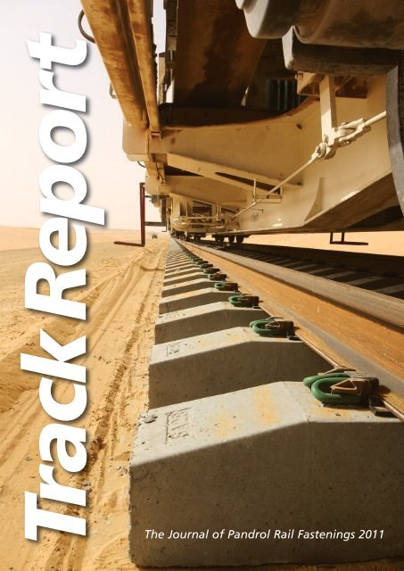
Front Cover: PANDROL FASTCLIP FC1600 Assemblies installed between Al Jouf and Hail on the North - South Line, Kingdom <strong>of</strong> Saudi Arabia.<br />
Back Cover: PANDROL FASTCLIP installed on High Speed Tracks, China.<br />
Track Report is published by <strong>Pandrol</strong> <strong>Rail</strong> <strong>Fastenings</strong> Ltd.,<br />
63 Station Road, Addlestone, Surrey KT15 2AR England.<br />
Telephone: +44 1932 834500<br />
Telefax: +44 1932 850858<br />
E-mail: info@pandrol.com<br />
Website: http://www.pandrol.com<br />
PANDROL, PANDROL FASTCLIP, PANDROL ’e’ Clip and<br />
PANDROL VIPA are registered trademarks <strong>of</strong> <strong>Pandrol</strong><br />
Limited. VANGUARD is a trademark <strong>of</strong> <strong>Pandrol</strong> Ltd except<br />
in North America where this name is used by Nortrak for<br />
a check rail design.<br />
<strong>Pandrol</strong> <strong>Rail</strong> <strong>Fastenings</strong> gratefully acknowledges the<br />
co-operation <strong>of</strong> all those contributing to the production<br />
<strong>of</strong> this journal and who have given permission for the use<br />
<strong>of</strong> photographs.<br />
<strong>The</strong> technical information given in ’Track Report’<br />
was correct at the time <strong>of</strong> printing, but the company<br />
undertakes a continuing programme <strong>of</strong> research<br />
and development, and improvements may have since<br />
been introduced.
DIRECT FIXATION ASSEMBLIES<br />
VANGUARD in Singapore<br />
by S C BARLOW, S J COX and A WANG,<br />
<strong>Pandrol</strong> <strong>Fastenings</strong> Ltd, 63 Station Road, Addlestone, Surrey, KT15 2AR, UK;<br />
J T NG, Senior Project Engineer and L S TAN, Senior Project Manager,<br />
Trackwork, Circle and Downtown Lines, <strong>Rail</strong> Group, LTA, Block 11, 1 Hampshire Road, Singapore<br />
Increasingly, environmental legislation aims<br />
to control the amount <strong>of</strong> vibration energy<br />
that can be transmitted into sensitive<br />
structures adjacent to railways. Where new<br />
buildings are erected it can be the case that<br />
the structures themselves are isolated using<br />
resilient bearings. It is most common,<br />
however for the railway itself to be treated<br />
by means <strong>of</strong> resilient track supports. This is<br />
known as “vibration isolation at source”.<br />
In tunnels on Singapore MRT, the track<br />
formation is concrete slab. Slab track has<br />
evolved considerably over the last few decades<br />
and there are numerous rail fastening options<br />
available to the track designer. Principal amongst<br />
these is the resilient baseplate, which directly<br />
anchors the rail to the correct alignment.<br />
LOW STIFFNESS BASEPLATES<br />
<strong>The</strong> baseplate most widely used on Singapore<br />
MRT slab track is the Double FASTCLIP (DFC)<br />
(Figure 1). It is characterised by having four<br />
FASTCLIP spring fastener clips per rail seat. Two<br />
outer FASTCLIPS fix a baseplate on a resilient<br />
studded rubber pad. Two inner FASTCLIPS<br />
anchor the rail on top <strong>of</strong> another resilient<br />
rubber rail seat pad.<br />
As with all baseplates that utilise spring clip<br />
fasteners, there are limits to the lowest vertical<br />
stiffness that can be provided. Since the<br />
efficiency <strong>of</strong> fastener vibration isolation is<br />
directly related to low vertical stiffness, spring<br />
clip fasteners are useful to a point, but for<br />
increased vibration mitigation alternative track<br />
support products must be considered.<br />
Typically, DFC has a vertical static secant<br />
stiffness <strong>of</strong> around 20kN/mm. In order to<br />
significantly improve the vibration performance<br />
<strong>of</strong> such a fastener, a step change in the vertical<br />
stiffness value is required.<br />
It was on recognising the limitations <strong>of</strong><br />
conventional baseplate technology during the<br />
1990s that <strong>Pandrol</strong> began to work on what<br />
developed into the <strong>Pandrol</strong> VANGUARD system<br />
for control <strong>of</strong> railway vibrations. This works on<br />
Figure 1 Original <strong>Pandrol</strong> DFC Assembly<br />
a quite different principle to conventional<br />
baseplates, in supporting the rail under its head<br />
rather than at its foot.<br />
<strong>The</strong> wedge-shaped elastomeric elements<br />
are compressed against the rail, so that as well<br />
as being supported, the rail is also fastened to<br />
the track foundation and maintains the<br />
required resistance to longitudinal loads. <strong>The</strong><br />
principal advantage <strong>of</strong> the system over more<br />
conventional rail fastenings is that it allows<br />
significantly greater vertical deflections under<br />
traffic without unacceptably high rail roll. <strong>The</strong><br />
low stiffness <strong>of</strong> the track leads to an improved<br />
attenuation in the dynamic forces generated<br />
at the wheel-rail interface, reducing the level<br />
<strong>of</strong> dynamic forces transmitted through the<br />
fastening, into the track foundation<br />
and beyond.<br />
<strong>The</strong>se elastic elements now act in shear,<br />
rather than in compression, which is the case<br />
with DFC. Natural rubber, which also provides<br />
Figure 2 VANGUARD DFC Retr<strong>of</strong>it<br />
resilient vertical support in DFC, exhibits<br />
outstanding dynamic performance when used<br />
in the shear mode in the VANGUARD assembly.<br />
Unlike a permanently bonded baseplate, the<br />
whole system does not need to be replaced if<br />
the rubber eventually wears in time – the<br />
rubber elements can be removed and replaced<br />
in-situ.<br />
Using this system <strong>Pandrol</strong> VANGUARD<br />
delivers a vertical static stiffness <strong>of</strong><br />
approximately 5 kN/mm and a dynamic<br />
stiffness <strong>of</strong> around 7 kN/mm in a safe manner<br />
and without excessive rail roll. <strong>The</strong> loaded track<br />
resonance <strong>of</strong> <strong>Pandrol</strong> VANGUARD in<br />
combination with typical railway vehicles -<br />
which have an un-sprung wheel mass in the<br />
range 600-900kg – occurs in the low 20’s <strong>of</strong><br />
Hz. This means that the <strong>Pandrol</strong> VANGUARD<br />
system is effective in eliminating many railway<br />
vibration problems.<br />
In 2008, together with the LTA, <strong>Pandrol</strong> set<br />
about designing a version <strong>of</strong> the VANGUARD<br />
system that would directly retr<strong>of</strong>it into the<br />
3
DIRECT FIXATION ASSEMBLIES<br />
the equilibrium speed was 46kmh. Singapore<br />
MRT uses UIC60 head-hardened rail with a<br />
fastener spacing <strong>of</strong> 700mm. <strong>The</strong> trial was<br />
conducted during September 2009. At this<br />
time the CCL2 was not open to revenue traffic,<br />
hence test trains were running at tare weight.<br />
MEASUREMENT AND RECORDING<br />
Readings <strong>of</strong> rail dynamic deflection, slab<br />
vibration and tunnel wall vibration were taken.<br />
Figure 3 VANGUARD DFC Retr<strong>of</strong>it in track<br />
locating shoulders used by the DFC baseplate.<br />
Retr<strong>of</strong>itting VANGUARD for DFC (Figure 2)<br />
is a direct swap. This has advantages for<br />
Singapore MRT in terms <strong>of</strong> a reduced<br />
stockholding inventory. <strong>The</strong>re is no change<br />
to the track structure or the means <strong>of</strong><br />
anchoring the baseplate. <strong>The</strong> rail will remain in<br />
the same position geometrically for both<br />
fasteners. By swapping to VANGUARD from<br />
DFC, large reductions in ground vibration can<br />
be achieved with minimal impact on<br />
operational parameters.<br />
In a trial, the rate <strong>of</strong> baseplate changeover<br />
from DFC to VANGUARD was timed at 40 units<br />
per hour.<br />
SCOPE OF STUDY<br />
Having devised a concept for a retr<strong>of</strong>it<br />
VANGUARD baseplate and demonstrated its<br />
function and safety in laboratory tests, a full<br />
live track trial was proposed (Figure 3). For this<br />
new application on Singapore MRT, the<br />
purpose <strong>of</strong> a track trial was tw<strong>of</strong>old. Firstly, to<br />
demonstrate the ease with which this new<br />
VANGUARD fastener could replace existing<br />
DFC. Secondly, to show the typical reductions<br />
in vibration that could be achieved on the<br />
tunnel floor. A 40 metre length <strong>of</strong> single track<br />
was chosen to confirm both conjectures – see<br />
map Figure 4.<br />
<strong>The</strong> track chosen was on a curve <strong>of</strong> 300<br />
metre radius. Superelevation was 80mm and<br />
<strong>Rail</strong> deflection<br />
Deflections <strong>of</strong> the rail relative to the concrete<br />
slab were measured using strain gauge<br />
displacement transducers. <strong>The</strong> transducers<br />
were mounted on brackets, which were fixed<br />
to metal plates glued down to the slab. <strong>The</strong><br />
transducers measure deflections <strong>of</strong> up to<br />
±5mm, with an accuracy <strong>of</strong> 0.1%. All<br />
deflection measurements were made at midspan<br />
between baseplate positions.<br />
Vibration measurement<br />
<strong>Rail</strong> vertical and lateral vibration was measured<br />
on both gauge and field side rails using<br />
calibrated accelerometers. Concrete slab<br />
vibrations were measured on the centre line <strong>of</strong><br />
the track and at mid-span relative to the rail<br />
fastening assemblies. In addition tunnel wall<br />
vibration measurements were taken in both the<br />
lateral and vertical axes.<br />
RESULTS AND DISCUSSION<br />
<strong>The</strong> average speed <strong>of</strong> the trains was measured<br />
to be 61km/h and all trains travelling between<br />
60km/h to 62km/h were analysed. Recordings<br />
for trains within this speed bracket were<br />
averaged. <strong>The</strong> vertical deflections <strong>of</strong> the rail<br />
foot at both field and gauge side were<br />
averaged to estimate the rail deflection at the<br />
centre. <strong>The</strong> rail roll was calculated by<br />
subtracting the field side recordings from the<br />
gauge side recordings. This method was used<br />
because the gauge and field side deflections<br />
can be easily found by adding and subtracting<br />
the roll component to the centre position. <strong>The</strong><br />
rail head lateral deflection was calculated by<br />
multiplying an appropriate factor derived from<br />
the geometry <strong>of</strong> the rail to the rail roll and then<br />
adding the average lateral deflection <strong>of</strong> the rail<br />
foot. This multiplying factor is the ratio<br />
between the height <strong>of</strong> the gauge corner and<br />
half the width <strong>of</strong> the rail base.<br />
Figure 4 VANGUARD Trial Site<br />
4
DIRECT FIXATION ASSEMBLIES<br />
Vertical<br />
(mm)<br />
Foot Lateral<br />
(mm)<br />
Roll<br />
(mm)<br />
Head Lateral<br />
(mm)<br />
DFC VG DFC VG DFC VG DFC VG<br />
Leading axle -0.87 -3.57 0.56 0.75 0.36 0.08 1.31 0.92<br />
High <strong>Rail</strong><br />
Trailing axle -0.86 -3.48 0.05 0.32 0.02 -0.12 0.10 0.06<br />
Average -0.86 -3.52 0.31 0.53 0.19 -0.02 0.71 0.48<br />
Figure 5 Slab centre vibration<br />
Leading axle -0.75 -2.81 0.57 -0.90 0.56 1.00 1.76 1.20<br />
Low <strong>Rail</strong><br />
Trailing axle -0.83 -3.34 0.11 -0.65 0.13 0.58 0.39 0.58<br />
Average -0.79 -3.08 0.34 -0.78 0.35 0.79 1.07 0.89<br />
Average -0.83 -3.30<br />
Table 1<br />
<strong>Rail</strong> deflection<br />
<strong>The</strong> mean deflection values for both the leading<br />
and trailing axles on low and high rails are given<br />
separately as shown in Table 1. Negative vertical<br />
values represent a downward deflection relative<br />
to the slab. Positive values for the rail roll and<br />
lateral deflection indicate a gauge increase or<br />
outward deflection from the track centre line.<br />
<strong>The</strong> maximum lateral deflection <strong>of</strong> the head <strong>of</strong><br />
the rail is shown in bold.<br />
Averaging all leading and trailing axles on all<br />
bogies reveals that the net rail vertical deflection<br />
for DFC and VANGUARD is 0.83mm and 3.30mm<br />
respectively. <strong>The</strong> maximum rail head lateral<br />
deflection values for the DFC and VANGUARD<br />
fastening systems are 1.76mm and 1.20mm<br />
respectively. It is therefore clear that VANGUARD<br />
has a much lower vertical stiffness than DFC<br />
without compromising the lateral rail stability.<br />
Slab and tunnel wall vibration<br />
On the slab the frequency range <strong>of</strong> greatest<br />
interest for vibration is between 20 and 500Hz.<br />
This is because the vibration is transmitted<br />
through the ground before it can reach<br />
buildings and cause annoyance, and the<br />
ground acts as a filter, which attenuates high<br />
frequencies. Hence, the lower frequencies<br />
measured on slab are those <strong>of</strong> most interest.<br />
Figure 5 shows the one-third octave band<br />
spectra <strong>of</strong> the slab centre in the vertical<br />
direction. <strong>The</strong>re are peaks in the response at<br />
50Hz band with the DFC and 25Hz with<br />
the VANGUARD, which correspond to loaded<br />
track resonance.<br />
Figure 6 shows the same results, plotted as<br />
insertion loss measured on the slab. <strong>The</strong><br />
vibration insertion loss in the vertical direction<br />
is about 10dB at 50Hz and 6.3dB in total<br />
velocity level.<br />
<strong>The</strong> tunnel wall 1 /3 octave band vibration<br />
spectra in the vertical axis is shown in Figure 7.<br />
<strong>The</strong> tunnel wall 1 /3 octave band vibration<br />
spectra in the horizontal axis is shown in Figure 8.<br />
<strong>The</strong> total vibration velocity levels in lateral<br />
and vertical directions are shown in Figure 9.<br />
CONCLUSIONS<br />
Average rail deflection in the vertical direction<br />
has been shown to be 0.83mm for DFC and<br />
3.30mm for VANGUARD, whilst lateral rail<br />
deflections remain more or less the same for<br />
both fasteners. This demonstrates one principle<br />
advantage <strong>of</strong> VANGUARD, which is that it will<br />
prevent excessive rail roll whilst providing very<br />
low vertical stiffness.<br />
<strong>The</strong> main purpose for installing PANDROL<br />
VANGUARD system is to reduce transmitted<br />
vibration and the slab insertion loss showed a<br />
substantial vibration reduction <strong>of</strong> 10dB at 50Hz<br />
and 5.7dB overall.<br />
This means that the VANGUARD rail<br />
fastener can be swapped for DFC to<br />
substantially reduce ground borne vibration in<br />
areas <strong>of</strong> high sensitivity.<br />
<strong>The</strong> Singapore MRT authorities now have a<br />
new option for combating ground vibration<br />
where this has reached nuisance levels.<br />
VANGUARD can be deployed as a fastener for<br />
new lines in areas where higher attenuation is<br />
required than can be provided with<br />
conventional fastening systems.<br />
In both new and retr<strong>of</strong>it applications the<br />
DFC fastener can be simply swapped for<br />
VANGUARD without any geometrical<br />
implications on the track. n<br />
Figure 6 Slab insertion loss (VANGUARD vs DFC)<br />
Figure 7 Tunnel wall vertical axis<br />
Figure 8 Tunnel wall horizontal axis<br />
Figure 9 Total vibration levels<br />
5
DIRECT FIXATION ASSEMBLIES<br />
<strong>Pandrol</strong> Success at Belgrade Central Station<br />
Construction <strong>of</strong> <strong>Rail</strong>way Tracks on Continuous Concrete<br />
Slabs in Belgrade Central <strong>Rail</strong>way Station<br />
Overview <strong>of</strong> the construction area<br />
Belgrade Central <strong>Rail</strong>way Station is a<br />
passenger station with 10 tracks/platforms,<br />
designed as a part <strong>of</strong> the main railway<br />
station in the City <strong>of</strong> Belgrade. In the city<br />
transport system, Belgrade Central <strong>Rail</strong>way<br />
Station together with the New Belgrade<br />
station and the standing platform “Vukov<br />
spomenik” will form part <strong>of</strong> the urban mass<br />
transport system and stations on the<br />
underground line. <strong>The</strong> Station will be<br />
constructed at ground level and covered<br />
with 50,000 m 2 <strong>of</strong> concrete slab, which will<br />
be the base for a Commercial Centre and<br />
internal traffic network with parking lots<br />
and connection to the city street network.<br />
Belgrade City administration decided to<br />
improve their entire public transport system,<br />
and this included improving urban rail transport<br />
as well. One <strong>of</strong> the main investments was<br />
construction <strong>of</strong> missing tracks in Belgrade<br />
Central <strong>Rail</strong>way Station. <strong>The</strong> Contract for<br />
construction <strong>of</strong> the Tracks 5 and 6 in the<br />
station was signed in December 2009 and<br />
certificates for works issued in June 2010. <strong>The</strong><br />
Station construction started with operations<br />
based on a temporary certificate for use on<br />
June 31st 2010.<br />
Prior to the construction <strong>of</strong> tracks 5 and 6,<br />
operations in the Station had been performed<br />
on only two tracks (9 and 10) out <strong>of</strong> 10<br />
planned tracks. <strong>The</strong>se tracks were constructed<br />
on classical permanent way with ballast,<br />
wooden sleeper and rigid “K“ fastenings.<br />
Design documentation was carried out by the<br />
Consultant – Traffic Institute CIP, Belgrade. CIP’s<br />
consultants envisaged tracks 5 and 6 to be built<br />
on continuous reinforced concrete slabs<br />
equipped with state <strong>of</strong> the art elastic fastenings<br />
and resilient rail pads, a modern system which<br />
would be used for the first time on the Serbian<br />
<strong>Rail</strong>ways network.<br />
<strong>The</strong> main contractors responsible for the<br />
installation on behalf <strong>of</strong> Serbian State<br />
<strong>Rail</strong>ways were Energoprojekt, who in turn<br />
subcontracted the Permanent Way works to a<br />
6
DIRECT FIXATION ASSEMBLIES<br />
specialised subcontractor,<br />
ZGOP-Novi Sad, who<br />
undertook the installation <strong>of</strong><br />
the superstructure and<br />
concrete slab track. Both<br />
companies worked closely<br />
with CIP and <strong>Pandrol</strong> when<br />
specifying the track<br />
construction method and rail<br />
fastening product to meet the<br />
requirements <strong>of</strong> the client.<br />
Track numbers 5 and 6<br />
were constructed under the<br />
covered reinforced concrete<br />
slab level 105, between the<br />
existing platforms, a total<br />
length <strong>of</strong> 460m. <strong>The</strong> width <strong>of</strong><br />
the concrete base plate is<br />
PANDROL VANGUARD in the station area<br />
4,08m and thickness 30cm.<br />
<strong>The</strong> Concrete was <strong>of</strong> C40 quality with<br />
polypropylene fibre added to a mix ratio <strong>of</strong><br />
900gr/m3. Construction joints were at 6m<br />
spacing and expansion joints set at 48m apart.<br />
It was a key design concern that any<br />
vibration generated by train traffic was not<br />
transmitted into the structure, thereby causing<br />
disruption to the retail units above. <strong>The</strong> EN60E1<br />
rails were fixed with VANGUARD rail fastenings<br />
produced by the reputable manufacturer<br />
<strong>Pandrol</strong> UK, from Great Britain. <strong>The</strong>se baseplate<br />
assemblies have a very low vertical stiffness,<br />
providing high levels <strong>of</strong> vibration isolation,<br />
without compromising the retention <strong>of</strong> track<br />
gauge, and reduce noise and vibration by<br />
preventing them being transmitted through the<br />
concrete base plate, subbase and to the<br />
foundation <strong>of</strong> the columns and structure <strong>of</strong> the<br />
upper concrete slab.<br />
This feature was <strong>of</strong> great importance to<br />
limit noise to the level specified in the track<br />
design standards, hence reducing noise<br />
disruption to the occupants <strong>of</strong> the retail space<br />
above the concrete slab on level 105.<br />
Connections <strong>of</strong> the concrete slab track<br />
within the platforms and the ballasted tracks<br />
outside the platforms were made by using<br />
transitional sections on one end length <strong>of</strong><br />
L=11,70 and on the other end length <strong>of</strong><br />
L=7,80, using the VIPA elastic baseplate<br />
fastening system manufactured by <strong>Pandrol</strong> UK.<br />
This transition stage was necessary as the<br />
change in stiffness from the ballasted track<br />
outside the platforms to the VANGUARD<br />
section on slab track meant trains would<br />
experience too large a change in stiffness over<br />
a very short length <strong>of</strong> track.<br />
Trackwork on the section approaching the<br />
Station did not require protection from noise<br />
and vibration, and was constructed using prestressed<br />
concrete sleepers in ballast with prestressed<br />
type B70 equipped with the FASTCLIP<br />
FE fastenings from <strong>Pandrol</strong> UK. Again, the rail<br />
type was EN60E1.<br />
Serbian State <strong>Rail</strong>ways’ existing concrete<br />
sleeper Putevi-Invest Stalac, who are the only<br />
supplier <strong>of</strong> the FASTCLIP fastening in the<br />
region, adapted their moulds to produce<br />
FASTCLIP FE sleepers on an existing<br />
approved sleeper design. <strong>The</strong>se sleepers were<br />
used on the sections <strong>of</strong> track leading up to the<br />
Station building, where vibration isolation<br />
Transition track<br />
was not as important.<br />
This track system comprising <strong>of</strong><br />
VANGUARD and VIPA fastenings on concrete<br />
slabs and FASTCLIP on ballast is a unique<br />
system providing an ingenious technical<br />
solution to meet the need for reduced noise<br />
and vibrations. It also <strong>of</strong>fered additional<br />
benefits, such as a longer period <strong>of</strong> track<br />
exploitation, minimum maintenance costs,<br />
simple cleaning <strong>of</strong> the platform track section<br />
and aesthetic effects fit to the station space.<br />
Belgrade is one <strong>of</strong> a few European cities to<br />
install these types <strong>of</strong> rail fastenings assemblies<br />
to try and reduce environmental noise pollution<br />
from railway traffic.<br />
Track construction was by the ‘Top Down’<br />
method. <strong>The</strong> rails, pre-assembled with the<br />
VANGUARD fastening, were suspended by<br />
track jigs to obtain line and level. Anchor studs<br />
were then core-drilled into the base slab,<br />
before a grout plinth was poured. Two lines<br />
were constructed using this method.<br />
<strong>Pandrol</strong> supported the client and<br />
contractor throughout the installation,<br />
achieving an excellent result and a satisfied<br />
client. <strong>The</strong>re are eight more tracks to be<br />
installed through the Station, and there is every<br />
confidence that these will utilise <strong>Pandrol</strong><br />
brand products.<br />
<strong>The</strong> track has now been opened to traffic,<br />
with approximately one train every 20 minutes<br />
on each track and it is clear that VANGUARD is<br />
reducing vibration into the structure, as even<br />
with a combination <strong>of</strong> passenger and freight<br />
trains travelling through the station, the<br />
amount <strong>of</strong> vibration felt on the platform is<br />
minimal. n<br />
PANDROL FASTCLIP FE in ballasted track Photographs by Mr Miloš Mrdjenovic´<br />
7
VANGUARD on São Paulo Metro, Brazil<br />
Vibration and Secondary Noise Reduction<br />
with PANDROL VANGUARD<br />
DIRECT FIXATION ASSEMBLIES<br />
Strain Gauges<br />
<strong>The</strong> PANDROL VANGUARD fastening system<br />
was recently installed in a section <strong>of</strong> Line 1<br />
on the Metro São Paulo in Brazil. A total <strong>of</strong><br />
1,600 units were installed, 900 on concrete<br />
slab track and 700 on timbers (embedded in<br />
concrete), substituting Landis and Vossloh<br />
plates respectively.<br />
As part <strong>of</strong> the homologation procedure<br />
requested by Metro SP, vibration measurements<br />
were performed on the track and in nearby<br />
buildings both before and after installation <strong>of</strong><br />
the VANGUARD fastenings (Figure 1).<br />
<strong>The</strong> section where these fastenings were<br />
installed is a slab track without floating slab or<br />
ballast, therefore any reduction in vibration is<br />
due exclusively to the performance <strong>of</strong> the<br />
fastenings. Alongside the vibration reduction<br />
requirement, the track gauge had to be<br />
guaranteed, even in extreme conditions, such<br />
as when rails break.<br />
In order to prove the performance <strong>of</strong> the<br />
fastenings, trials in the track under loaded<br />
LVDTs<br />
Figure 1 Track measurements<br />
trains, and measurements in nearby buildings<br />
were performed as part <strong>of</strong> an extensive<br />
investigating program. In addition, a<br />
computerized numerical model was prepared<br />
to simulate a rail break. <strong>The</strong> aim <strong>of</strong> the trials<br />
was to measure the acceleration against the<br />
time, the speed and sound pressure level in the<br />
frequency field.<br />
Accelerometers<br />
As well as vibration trials on the track, rail<br />
strains, vertical and horizontal displacement,<br />
gauge widening and dynamic stiffness were<br />
recorded. <strong>The</strong>se measurements were used in<br />
the numerical model, based on finite elements,<br />
for the case <strong>of</strong> a supposed accidental rail break.<br />
8
DIRECT FIXATION ASSEMBLIES<br />
NUMERICAL MODELING<br />
<strong>The</strong> first step for analysis is to establish the dynamic<br />
stiffness <strong>of</strong> the track. This was derived from the rail<br />
foot strain and the “Beam on Elastic Support”<br />
theory by an interactive process. <strong>The</strong> result was a<br />
vertical axle load <strong>of</strong> 15,5 ton. For this load, the<br />
maximum vertical displacement between two<br />
fastenings with a spacing <strong>of</strong> 750mm was 4,38mm<br />
downwards, as shown in Figure 3.<br />
Also, it is very important during fastenings<br />
homologation to satisfy the requirement for gauge<br />
widening (lateral displacement) which is limited to<br />
3mm in normal working conditions. With PANDROL<br />
VANGUARD the gauge widening measured<br />
obtained in the trials was approximately 1,2mm,<br />
complying perfectly with the requirement.<br />
Now simulating the accidental rail break<br />
between two fastenings (Figure 2), the gauge<br />
widening predicted by the numerical model was<br />
around 8,00mm. So for this safety critical factor,<br />
a horizontal strength equal to 15% <strong>of</strong> the<br />
vertical strength was derived, which was also<br />
deemed acceptable.<br />
Figure 3 Regular rail displacement<br />
Broken rail<br />
Figure 2 Broken rail simulation<br />
Figure 4 Vibration measurements<br />
CONCLUSION<br />
One <strong>of</strong> the main reasons to change the original<br />
fastenings to PANDROL VANGUARD was the<br />
high vibration level. That was around 78,8dBV<br />
at 25Hz in the nearby buildings, at 25 meters<br />
from the tracks. After the VANGUARD<br />
installation, the global vibration level was<br />
reduced to 66,2dBV at the same frequency and<br />
location (Figure 4).<br />
Regarding the secondary noise measured<br />
in the nearby buildings, the trial results showed<br />
that after installation <strong>of</strong> PANDROL VANGUARD,<br />
the noise measured was less than the limit<br />
value given in Brazilian law.<br />
A final analysis was possible regarding the<br />
natural frequency <strong>of</strong> the system before and<br />
after. Prior to replacement, the natural<br />
frequency was approximately 25Hz. After, the<br />
natural frequency changed to approximately<br />
16Hz as a result <strong>of</strong> the lower track stiffness,<br />
causing a vibration diminution in frequency<br />
bands between 16Hz and 25Hz that was not<br />
previously present.<br />
Based on the obtained results, it can be<br />
concluded that PANDROL VANGUARD showed<br />
a fully satisfactory performance. n<br />
Fig 5 Finished track<br />
9
DIRECT FIXATION PANDROL ASSEMBLIES FASTCLIP<br />
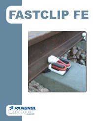
PANDROL FASTCLIP FE<br />
PANDROL FASTCLIP FE is the latest<br />
generation rail fastening from <strong>Pandrol</strong>,<br />
a value engineered variant <strong>of</strong> the<br />
FASTCLIP system, which can be used in<br />
all applications where FASTCLIP FC is<br />
currently used.<br />
Commercial pressures to continually drive<br />
down costs within the railway industry and<br />
comments from railway contractors initiated a<br />
engineering exercise based upon the current<br />
PANDROL FASTCLIP system to try and achieve<br />
significant overall cost savings for railway<br />
operators, without any compromise to the<br />
performance <strong>of</strong> the assembly.<br />
FASTCLIP FE<br />
FASTCLIP FE is identical to FASTCLIP FC in<br />
the following respects:<br />
• <strong>The</strong> system remains a captive system.<br />
• It is delivered to site installed on each sleeper.<br />
• Sleeper makers assemble all the components<br />
on each sleeper prior to delivery.<br />
• It is designed for mechanised track renewals,<br />
using automated clipping machines or hand-tools.<br />
• <strong>The</strong> system uses an M shaped clip, driven at<br />
right angles to the rail.<br />
• Designed for 26 T axle loads.<br />
Exploded view<br />
<strong>The</strong> benefits that FASTCLIP FE <strong>of</strong>fers are:<br />
• Shoulders not susceptible to accidental<br />
damage.<br />
• Robust toe insulators.<br />
• A few, simple hand-tools.<br />
• Easy to use in the concrete sleeper factory.<br />
<strong>The</strong> design and manufacturing processes<br />
for the clip itself ensure that the high<br />
performance <strong>of</strong> <strong>Pandrol</strong> systems is maintained<br />
but steel is used very efficiently.<br />
One <strong>of</strong> the key features <strong>of</strong> the FE system is<br />
a new plastic seal plate, which seals the hole in<br />
the sleeper mould and is then cast into the<br />
sleeper. This minimises contact between the<br />
steel mould and the cast iron shoulder <strong>of</strong> the<br />
assembly, increasing mould life. It also prevents<br />
slurry leakage into the shoulder during the<br />
casting process, increasing the quality <strong>of</strong> the<br />
final product.<br />
10
PANDROL FASTCLIP<br />
Rosenqvist CD200 installation machine for FASTCLIP<br />
PANDROL MARK1V FASTCLIP installation machine<br />
SUCCESSFUL TRIALS OF PANDROL<br />
FASTCLIP FE<br />
<strong>Pandrol</strong> UK has been undertaking trials <strong>of</strong> the<br />
new ‘FASTCLIP FE’ rail fastening in Hungary,<br />
Romania and Norway. Each <strong>of</strong> these projects<br />
has used a different installation method and<br />
various combinations <strong>of</strong> machines and<br />
manpower. On all the sites, the work was<br />
completed quickly and efficiently and was well<br />
received by the local contractors.<br />
Vortok and Rosenqvist, both subsidiaries <strong>of</strong><br />
<strong>Pandrol</strong>, have also been involved in the<br />
development and implementation <strong>of</strong> the<br />
FASTCLIP FE system. An FE compatible version <strong>of</strong><br />
the successful Vortok Stressing Roller (the FeVSR)<br />
has been used successfully in Hungary, allowing<br />
for very quick and safe stressing operations.<br />
Rosenqvist’s high-output clipping machines are<br />
easily adjustable for use on FE assemblies,<br />
including the Clip Master units attached to the<br />
Rosenqvist SB60 Sleeper Changer, which was<br />
used in the Norwegian trial.<br />
<strong>Pandrol</strong> UK and other subsidiaries have<br />
further trials planned in the upcoming months<br />
including a heavy haul version going into tracks<br />
in Australia and Brazil.<br />
11
PANDROL FASTCLIP<br />
Case Study: FASTCLIP FE installation on MAV tracks, Hungary<br />
<strong>The</strong> first installation <strong>of</strong> FASTCLIP FE in Hungary took place on tracks run and maintained by MAV. <strong>The</strong> installation site was 300m from the<br />
station at Zichyújfalu, near Gardony on the Szekesfeheruar to Pusztaszabolcs line. Installation work was carried out by the contractor Mavepcell.<br />
1. 300 FASTCLIP FE sleepers with UIC54 rails were<br />
supplied by <strong>Rail</strong>One Labatlan and delivered to the<br />
installation site by road.<br />
4. <strong>The</strong> rails were bolted up to existing rails at the<br />
end <strong>of</strong> a crossing using temporary joints.<br />
7. Vortok Stressing Rollers (VSRs) were placed at a<br />
spacing <strong>of</strong> 12 sleepers in the curved section <strong>of</strong>f the<br />
back <strong>of</strong> the S&C, and at 15 sleeper spacing on the<br />
straight. This increased spacing was because both<br />
rails were being stressed simultaneously. Once<br />
installed, the raising <strong>of</strong> the rail into the stressing<br />
position took only five minutes. Once the MAV<br />
engineers were happy that the stress was<br />
distributed through the rail, the VSRs were dropped<br />
and every fifth sleeper clipped up prior to welding.<br />
2. Sleepers were unloaded using a road-railer and<br />
moved into position using the <strong>Pandrol</strong> 4-sleeper<br />
lifting beam and lifting chains.<br />
5 A 5-man working team began the clipping work,<br />
using clip installers and sleeper lifting tools where<br />
required. Stressing <strong>of</strong> the tracks took place<br />
approximately three weeks later. <strong>The</strong> rail was to be<br />
stressed naturally, without tensor or rail warming<br />
equipment, so work was delayed slightly until the rail<br />
temperature was within the range <strong>of</strong> 15°C-23°C.<br />
3. <strong>The</strong> sleepers were spaced with a tape measure<br />
and aligned to a string line on a bed prepared by<br />
a bulldozer and roller. Once all 300 sleepers had<br />
been laid out and roughly aligned, the rails were<br />
threaded using a pair <strong>of</strong> road-railers.<br />
6. Walk-behind machines were used to unclip all<br />
300 sleepers, one machine on each rail, and the<br />
unclipping procedure was completed in under<br />
45 minutes.<br />
8. <strong>The</strong> welders dropped two welds, one on each rail,<br />
and after approximately 45 minutes, the<br />
remaining sleepers were clipped up. <strong>The</strong> total<br />
time taken to unclip, natural stress, weld and<br />
reclip 200m <strong>of</strong> track was four hours, including<br />
time spent demonstrating the use <strong>of</strong> the<br />
equipment to the MAV operatives. <strong>The</strong> FE<br />
installation was then complete, and the track<br />
opened to traffic on Thursday 10th September. n<br />
12
Kadiköy-Kartal Metro Line, Turkey<br />
Route overview<br />
THE PROJECT<br />
<strong>The</strong> Kadiköy-Kartal project involved the<br />
construction <strong>of</strong> a 22km long metro rail line<br />
on the Anatolian (Asian) side <strong>of</strong> Istanbul,<br />
which includes 16 metro stations. <strong>The</strong> aim<br />
<strong>of</strong> the project was to help reduce travel<br />
times and improve mobility along one <strong>of</strong><br />
the most congested traffic corridors on<br />
the Anatolian side <strong>of</strong> Istanbul, by providing<br />
a clean, safe and efficient mode <strong>of</strong><br />
public transit.<br />
<strong>The</strong> new line will relieve traffic congestion<br />
at peak hours by an equivalency <strong>of</strong> 100 buses<br />
and 4,300 minibuses, increasing the traffic flow<br />
capacity by about 30%.<br />
<strong>The</strong> alignment began in front <strong>of</strong> the<br />
Kadiköy landing stage and extends to the<br />
Kartal Interchange by following the route <strong>of</strong><br />
the D-100 highway corridor. <strong>The</strong> route meant<br />
the new line could be integrated with the<br />
metro system in the European Side <strong>of</strong> Istanbul,<br />
via the Marmaray Strait Tube Crossing at the<br />
transfer center planned at Ayrilikçeşme Station.<br />
<strong>The</strong> D-100 state highway is one <strong>of</strong> the<br />
most significant main arteries in the eastern<br />
Split <strong>of</strong> works<br />
side <strong>of</strong> Istanbul and sees intense traffic all day<br />
every day.<br />
This corridor is the artery which connects<br />
regions like Kartal, Pendik, Gebze and<br />
leads to the downtown and western sides <strong>of</strong><br />
Istanbul, and has become one <strong>of</strong> the most<br />
strategic regions <strong>of</strong> Istanbul, sociologically<br />
and economically.<br />
<strong>The</strong> line will relieve the E5 highway at peak<br />
hour by an equivalency <strong>of</strong> 100 buses and 4,300<br />
minibuses. This will increase the traffic flow<br />
capacity <strong>of</strong> about 30%.<br />
<strong>The</strong> Kadiköy-Kartal Metro Line was<br />
tendered for the first time in 2004 by the IETT<br />
(Istanbul Public Transportation Directorate) as<br />
surface LRT. <strong>The</strong> Contract for civil works<br />
was awarded to Yapi Merkezi-Dogus-Yuksel-<br />
Yenigun-Belen Insaat J.V, named AnadoluRay<br />
Consortium on 28.01.2005. <strong>The</strong> first contract<br />
value was 139 million USD. AnadoluRay began<br />
the works on 11.02.2005. However, after new<br />
studies by universities, local authorities reached<br />
a concensus that the line should be fully<br />
underground. As a natural consequence <strong>of</strong> this<br />
decision the total construction cost <strong>of</strong> the line<br />
increased. <strong>The</strong>refore, a new tender for the<br />
remaining part <strong>of</strong> the civil works and the whole<br />
line’s E&M works was completed.<br />
13
PANDROL Resilient baseplate assembly<br />
<strong>The</strong> new tender was won by Avrasya Metro<br />
Grubu (AMG JV) and a contract signed with the<br />
IMM, Head <strong>of</strong> Transportation Department, <strong>Rail</strong><br />
Systems Directorate on 06.03.2008. AMG JV<br />
consisted <strong>of</strong> ASTALDI (%42), MAKYOL (%41),<br />
and GÜLERMAK (%17) companies. Astaldi<br />
S.p.A was appointed as the leader <strong>of</strong> the JV.<br />
<strong>The</strong> new contract value was 751.256.043 Euro.<br />
AMG JV were in charge <strong>of</strong> Supplementary<br />
Construction and Supply, Assembly and<br />
Commissioning <strong>of</strong> Electromechanical Systems.<br />
<strong>The</strong> figure shown previously shows the split <strong>of</strong><br />
works between AnadoluRay and AMG JV. <strong>The</strong><br />
blue line shows the AMG JV’s responsibility for<br />
E&M works and station civil works. <strong>The</strong> red line<br />
shows tunnels to be built by the JV and the<br />
yellow line shows the section where<br />
AnadoluRay is responsible for the tunnelling<br />
job by means <strong>of</strong> TBMs.<br />
In order to comply with strict deadlines,<br />
both NATM and TBMs were used to complete<br />
the tunnelling. <strong>The</strong> alignment comprised 16<br />
stations to be carried out by open excavation<br />
and cut & cover systems according to location<br />
and site accessibility. Each station underpasses<br />
the E5 Motorway by means <strong>of</strong> an underground<br />
passage crossing the E5 horizontally and<br />
connecting the both ends.<br />
Daily average rates <strong>of</strong> 110m were achieved<br />
during the excavation progress, and 4.5 tonnes<br />
<strong>of</strong> explosives used everyday. 72% <strong>of</strong> the tunnel<br />
excavation works were completed by the<br />
Completed track<br />
14
end October 2009.<br />
Excavation works in all 16 stations also<br />
progressed very quickly, with the first station<br />
building construction finished by the end <strong>of</strong><br />
November 2009.<br />
PANDROL fastenings were used<br />
throughout the new line. <strong>The</strong> assembly<br />
supplied is similar to the e2007 e-clip baseplate<br />
assembly, which was installed on the Dubai<br />
metro project, but the version for Kadiköy –<br />
Kartal is more resilient at 15kN/mm, to meet<br />
the exacting specification <strong>of</strong> the railway.<br />
Variants <strong>of</strong> this solution have been<br />
operational in tracks worldwide for many years<br />
and provided the Operating Companies<br />
with an easy to use, low maintenance rail<br />
fastening assembly.<br />
<strong>The</strong> Greater Istanbul Municipality<br />
<strong>Rail</strong>way Authority (IBB) were closely involved in<br />
the decision to specify the <strong>Pandrol</strong> system,<br />
and continued to work closely with<br />
AMG throughout the tendering and<br />
evaluation/approval process. n<br />
Track construction on the Kadiköy-Kartal project<br />
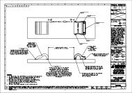
<strong>The</strong> track was built using a top-down construction methodology, using temporary construction plates to ensure that<br />
the concrete finish beneath the rail fastening assemblies was to an acceptable level. <strong>The</strong> construction plates used were<br />
made to a design agreed between <strong>Pandrol</strong> to AMG and provided fabrication work <strong>of</strong> a very high standard.<br />
1. With the first pour slab and exposed concrete<br />
reinforcement already in place, rails are placed<br />
and held to a rough alignment using track jigs.<br />
3. Next, laser alignment ensures the rails are<br />
accurately placed before wooden shuttering is<br />
built around them.<br />
5. Any extra concrete was cleaned <strong>of</strong>f using water and<br />
brushes and the concrete left to cure for 2-3 days<br />
before removing the construction plates. In areas<br />
where thermal expansion <strong>of</strong> the rail is expected, the<br />
rail clamps could be loosened or removed, once the<br />
concrete had sufficient strength to support the<br />
weight <strong>of</strong> the rails and fastening assemblies.<br />
2. Construction plates are attached to the rails<br />
and the anchor studs fixed into their<br />
correct positions.<br />
4. Assemblies were also covered in plastic to protect<br />
them, before the concrete is poured. <strong>The</strong> concrete<br />
was delivered by a mixer lorry and transported<br />
through the tunnels by barrow. Careful placement<br />
<strong>of</strong> the concrete meant that minimal use <strong>of</strong> poker<br />
vibrators was required and the surface was<br />
finished to a high standard by hand.<br />
6. With the concrete cured, the assemblies were built<br />
up over the cast-in anchors. <strong>The</strong> rails were then<br />
threaded and insulators and clips installed before<br />
tightening the nylock nuts to their working position.<br />
15
<strong>The</strong> Gautrain Project, South Africa<br />
DIRECT FIXATION PANDROL ASSEMBLIES FASTCLIP<br />
<strong>Rail</strong> transport in South Africa entered a new<br />
era with the successful opening <strong>of</strong> phase 1<br />
<strong>of</strong> the Gautrain rapid rail project on the 8th<br />
<strong>of</strong> June 2010. <strong>The</strong> opening came 3 weeks<br />
ahead <strong>of</strong> schedule and just 44 months after<br />
the first sod was turned.<br />
Within days <strong>of</strong> opening in time for the FIFA<br />
Soccer World Cup, the Gautrain was carrying<br />
approximately 80,000 passengers per week.<br />
Post world cup, the train service has stabilized<br />
at about 50,000 passengers per week with bus<br />
passengers at about 4,000 passengers per<br />
week and showing steady growth.<br />
<strong>The</strong> project is a Public-Private-Partnership<br />
and includes a 15-year maintenance and<br />
operating period after construction. Following<br />
an international tender process, the Gauteng<br />
Provincial Government awarded the project to<br />
the Bombela Concession Company consisting<br />
initially <strong>of</strong> Bombardier Transportation UK Ltd,<br />
Bouygues Travaux Publics SA, Murray & Roberts<br />
Ltd and SPG Concessions Ltd. Latterly<br />
ABSA Capital and the J&J Group have also<br />
taken up equity stakes in the Bombela<br />
Concession Company. <strong>The</strong> operations are led<br />
by RATP Development – the transit operator<br />
responsible for public transport in Paris and<br />
its surroundings.<br />
THE PROJECT<br />
Phase 1 <strong>of</strong> the project comprises an airport link<br />
between the Sandton CBD and OR Tambo<br />
International Airport; as well as two<br />
intermediate commuter stations – Marlboro<br />
and Rhodesfield. <strong>The</strong> balance <strong>of</strong> the project will<br />
be completed during <strong>2011</strong> and consists <strong>of</strong> six<br />
further commuter stations connecting the<br />
Johannesburg CBD with Pretoria and Hatfield.<br />
<strong>The</strong> project is designed to carry 100,000<br />
passengers per day at start-up.<br />
<strong>The</strong> network will be nearly 80km long once<br />
both Phases 1 and 2 are completed.<br />
<strong>The</strong> Gautrain <strong>of</strong>fers international standards<br />
<strong>of</strong> public transport with high levels <strong>of</strong> safety,<br />
reliability, predictability and comfort. Travelling<br />
at a maximum speed <strong>of</strong> 160 kilometres per<br />
hour, it will connect Hatfield Station with<br />
Johannesburg Park Station in about 42 minutes<br />
and Sandton station with OR Tambo<br />
International Airport in less than 15 minutes.<br />
<strong>The</strong> train service is complemented by a<br />
dedicated bus fleet which will transport<br />
passengers in air-conditioned comfort between<br />
the stations and surrounding suburbs and<br />
business nodes.<br />
Both the trains and the buses are accessible<br />
to people with disabilities.<br />
ROLLING STOCK<br />
Bombardier will supply a fleet <strong>of</strong> vehicles based<br />
on the tried and tested Electrostar train-set<br />
already in common service in the UK. In South<br />
Africa, they will be formed into four-car sets to<br />
carry up to about 450 passengers per train, and<br />
will run at 160km/h (100mph).<br />
<strong>The</strong> vehicles will be manufactured at<br />
Bombardier's Derby works in the UK with final<br />
Gauteng Province<br />
• 20% <strong>of</strong> South<br />
Africa’s population<br />
resides in Gauteng<br />
• 33% <strong>of</strong> the GDP is<br />
generated in<br />
Gauteng<br />
• Gauteng boasts<br />
the most<br />
developed<br />
infrastructure in<br />
South Africa<br />
• 52% <strong>of</strong> South<br />
Africa’s 7 million<br />
international<br />
tourists pass<br />
through Gauteng<br />
16
PANDROL FASTCLIP<br />
assembly taking place in South Africa. <strong>The</strong> fleet<br />
will be based at a purpose built maintenance<br />
facility located at Midrand, just South <strong>of</strong><br />
Allandale road.<br />
SIGNALLING AND<br />
COMMUNICATIONS<br />
An operational control centre (OCC) located at<br />
the Midrand depot controls all train<br />
movements as well as comprising a<br />
communications and control hub for the<br />
monitoring and control <strong>of</strong> the bus feeder<br />
system and key station and tunnel equipment.<br />
<strong>The</strong> signalling solution comprises<br />
Bombardier’s CITYFLO 250 system which is a<br />
fixed block signalling system based on ‘distance<br />
to go’ principles with vital information being<br />
transmitted to the onboard automatic train<br />
protection (ATP) system from balises in<br />
the track. <strong>The</strong> ATP supervises the driver and<br />
train movements.<br />
Communication points will be provided at<br />
stations for passenger information and safety.<br />
FARES & TICKETING<br />
Gautrain has a balanced approach in its fare<br />
policy aimed at making the service attractive<br />
and affordable to broad sectors <strong>of</strong> the<br />
population. In principle, Gautrain fares are<br />
designed to be lower than the cost <strong>of</strong> using a<br />
private car for the same journey but more<br />
expensive than those <strong>of</strong> existing public<br />
transport options.<br />
<strong>The</strong> fare collection system is based on a<br />
contactless smart-card (CSC) system, which<br />
enables customers to load a variety <strong>of</strong> different<br />
journey products, ranging from “top-up-andgo”<br />
to period passes, onto the same card and<br />
to re-use this card over and over again.<br />
Customers will have the opportunity to register<br />
their cards, which will enable immediate<br />
blacklisting <strong>of</strong> the card should it be lost or<br />
stolen. Any unutilised value on the lost card can<br />
then be transferred to a new card.<br />
So-called “Gautrain Gold Cards” are<br />
available from all ticket <strong>of</strong>fices and ticket<br />
vending machines at Stations as well as from<br />
selected <strong>of</strong>f-site retailers. <strong>The</strong> Gold Card allows<br />
seamless transfers between Gautrain’s bus,<br />
train and parking services. Customers using<br />
more than one service within a single journey<br />
also enjoyed a reduced fare. n<br />
17
PANDROL FASTCLIP<br />
Sri Lanka – Steel Sleepers for<br />
the Sri Lanka <strong>Rail</strong>ways Hill Sections<br />
by Dr M. Seshagiri RAO, FICE, FPWI, Rahee Track Technologies Pvt Ltd, Kolkata, India<br />
Passenger train in tea country<br />
Steel sleepers replacing life expired timber sleepers<br />
With the rising cost <strong>of</strong> timber and tighter<br />
environmental requirements, most World<br />
<strong>Rail</strong>ways started switching over to prestressed<br />
concrete sleepers in the 1970’s and<br />
1980’s. <strong>The</strong> <strong>Rail</strong>ways <strong>of</strong> timber rich Sri<br />
Lanka, however, continued the use <strong>of</strong><br />
wooden sleepers until recently. <strong>The</strong> present<br />
policy is to phase out the wooden sleepers<br />
to ensure conservation <strong>of</strong> forests . <strong>The</strong> price<br />
<strong>of</strong> timber has been increasing and the life <strong>of</strong><br />
wood in track has been going down tilting<br />
the economics in favour <strong>of</strong> other types.<br />
Many track renewals over the Southern and<br />
Eastern Lines <strong>of</strong> Sri Lanka <strong>Rail</strong>ways (SLR) are<br />
being constructed using PRC sleepers. <strong>The</strong><br />
Northern Line disrupted during the strife is<br />
being re-built with new rails on PRC<br />
sleepers and fresh ballast.<br />
<strong>The</strong> Central Line (also known as the main<br />
line, being the first <strong>Rail</strong>way <strong>of</strong> Ceylon) is special.<br />
It rises up into the tea country attaining the<br />
highest elevation for Broad Gauge in the World<br />
at nearly 2,000m at Pattipola. <strong>The</strong> gradients are<br />
steep (2.5% is very common) and the curves are<br />
sharp (100m radius). Consequently, long welded<br />
<strong>Rail</strong>s and pre-stressed concrete sleepers had to<br />
be ruled out.<br />
Steel sleepers require minimum use <strong>of</strong><br />
ballast and have a low life cycle cost. It is ideally<br />
suited for the hill sections with steep gradients<br />
where use <strong>of</strong> mechanized track laying<br />
equipment is restrictive. Proposals for the use <strong>of</strong><br />
steel sleepers <strong>of</strong> a design well established on the<br />
Bailadilla Hill <strong>Rail</strong>ways <strong>of</strong> India (also known as<br />
the KK Line) were initially made. However, the<br />
maximum axle load on SLR is only 20 T against<br />
that <strong>of</strong> 23 T in India. Freight traffic is rather<br />
modest against 30 GMT per annum on the KK<br />
line. Individual trainloads are also very low when<br />
compared to 5,200t on the KK line. It was<br />
therefore decided to use a value engineered<br />
sleeper section providing adequate strength.<br />
While a UIC standard code <strong>of</strong> practice<br />
exists for the design <strong>of</strong> PRC sleepers, there isn’t<br />
any for that <strong>of</strong> steel sleepers. Recourse had to<br />
be taken to the US or Australian codes and the<br />
Indian Standard IS 800 for the structural steel<br />
design. <strong>The</strong> Indian practice <strong>of</strong> 1:2 load<br />
distributions under the rail seat and 1/6 centre<br />
binding reaction were adopted. Different<br />
pr<strong>of</strong>iles <strong>of</strong> sleeper bars were considered and<br />
18
PANDROL FASTCLIP<br />
Initial trial installation<br />
Close up <strong>of</strong> FD 1408 assembly<br />
strength analysis was made by computer<br />
simulated s<strong>of</strong>twares. Finally, a rolled pr<strong>of</strong>ile<br />
section weighing 23.2kg/m was found to be<br />
most appropriate. Against a permissible stress<br />
<strong>of</strong> 17.1kg/sqmm, the calculated stresses did<br />
not exceed 15.08kg/sqmm. <strong>The</strong> Sri Lankan<br />
Government Design Bureau however desired<br />
that the worn-out (after 50-year life)<br />
geometrical properties should be taken into<br />
account and the centre binding reactions<br />
should be as for a beam on elastic foundations.<br />
This too was done using Prokon s<strong>of</strong>tware to<br />
confirm that the permissible stresses would still<br />
not be exceeded.<br />
<strong>The</strong> fastening system needed a lot <strong>of</strong><br />
detailed examination. Considering the<br />
curvatures, the lateral forces were bound to be<br />
large and the system needed a good lateral<br />
support as well as suitability for fitment <strong>of</strong><br />
check rails.<br />
After detailed examination, the PANDROL<br />
FASTCLIP model Type FD 1408 was adopted. Its<br />
hold is positive, lateral support excellent and it<br />
is possible not only to insert insulating liners but<br />
also to provide for extra gauge on sharp curves<br />
by using nylon insulating liners <strong>of</strong> different<br />
sizes. It needs special tools for installation but<br />
yet <strong>of</strong>fers a “fit and forget” arrangement.<br />
Installation <strong>of</strong> the FASCTCLIP needs<br />
shoulders, which, in PRC sleepers, are cast into<br />
the concrete. In the case <strong>of</strong> SLR sleepers, hookin<br />
shoulders have been used. <strong>The</strong>se are loose<br />
pieces, which are slipped into the rectangular<br />
hole in the sleeper and hold the PANDROL<br />
FASTCLIP firmly in position. Another advantage<br />
<strong>of</strong> FD Clip is its low pr<strong>of</strong>ile design, which<br />
protects the clip from getting entangled with<br />
any loose component <strong>of</strong> the rolling stock. It<br />
provides ample toe load on the rails, which is<br />
quite adequate to the requirements <strong>of</strong> SLR. <strong>The</strong><br />
clip contact points on the shoulder are less<br />
vulnerable to corrosion expansion. This poses a<br />
problem on coastal lines. <strong>The</strong> FD system is also<br />
very easy to inspect that it is installed in the<br />
correct working position due to the fact that<br />
the clips are applied laterally to the rail.<br />
Finished track after rehabilitation<br />
Materials in the insulator and pad provide<br />
greater longevity and are less susceptible to<br />
installation damage.<br />
After successful trials in stages, initially<br />
3,250 sleeper sets and later 50,000 sleeper sets<br />
with FD clips were ordered by Sri Lankan<br />
<strong>Rail</strong>ways, have been laid in track and have<br />
withstood two monsoons.<br />
We are illustrating the SLR track with a few<br />
photographs. Notwithstanding the limited<br />
ballast and occasional inadequacy <strong>of</strong> drainage,<br />
these sleepers appear to be behaving well. n<br />
19
PROJECTS<br />
Field Repair <strong>of</strong> Concrete Gauge Convertible<br />
Sleepers – Australian <strong>Rail</strong> Track Corporation (ARTC)<br />
by Ben LESKE, Infrastructure Manager East West, ARTC<br />
In 1990 the broad (1,600mm) gauge timber<br />
sleepers between Adelaide and Melbourne<br />
were replaced with gauge convertible<br />
concrete sleepers that would allow for<br />
future conversion to standard (1,435mm)<br />
gauge as part <strong>of</strong> the national mainline<br />
concrete re-sleepering and gauge<br />
standardisation program. This line was<br />
subsequently converted to standard gauge<br />
in 1995.<br />
<strong>The</strong> design <strong>of</strong> these sleepers, which allows<br />
for assembly <strong>of</strong> the track at either <strong>of</strong> the above<br />
track gauges, consists <strong>of</strong> one fixed rail seat that<br />
accommodates a single rail, and a ‘doublewidth’<br />
rail seat that has a central cast iron<br />
‘socket’ embedded within the sleeper. This<br />
central insert is used to attach a hook-in cast<br />
shoulder, which can be rotated depending<br />
on which <strong>of</strong> the two available track gauges<br />
are required.<br />
Once converted to standard gauge, the<br />
rotatable shoulder/socket combination became<br />
the rail restraining feature on the field side <strong>of</strong><br />
one end <strong>of</strong> the sleeper.<br />
In certain areas <strong>of</strong> this track, namely<br />
through the Adelaide Hills, high wear <strong>of</strong> both<br />
the sleeper insert and the rotatable shoulder<br />
became apparent after approximately 10 years<br />
<strong>of</strong> service. This wear has resulted from a<br />
combination <strong>of</strong> tight track curvature, trains up<br />
to 1,500 metres long with a combined loading<br />
<strong>of</strong> up to 5,000 tonnes, relatively high annual<br />
rainfall and heavy sanding <strong>of</strong> the track to aid<br />
locomotive traction.<br />
Not only was this wear causing obvious<br />
concerns with respect to the longevity and<br />
integrity <strong>of</strong> the sleepers, but it was also<br />
creating problems through excessive widening<br />
<strong>of</strong> the track gauge.<br />
In 2010 a repair system was developed by<br />
<strong>Pandrol</strong> that would restore the correct<br />
functionality <strong>of</strong> these sleepers whilst enabling easy<br />
track installation during short possession times.<br />
This system consists <strong>of</strong> a cast iron spacing<br />
plate that is inserted between the rotating<br />
shoulder and the now redundant broad gauge<br />
field-side shoulder. This plate is secured to the<br />
rotating shoulder by the existing rail fastening<br />
clip and an additional rail fastening clip is used<br />
to secure the plate to the otherwise redundant<br />
shoulder.<br />
Additionally, to re-instate the assembly<br />
prior to clipping up, the now worn rotating<br />
shoulder is replaced with a new unit, and<br />
secured to the worn insert using a high<br />
strength epoxy.<br />
Following successful repeated load testing<br />
<strong>of</strong> the assembly to 3 million cycles in the<br />
laboratory, a field trial was conducted with<br />
satisfactory results in terms <strong>of</strong> both system<br />
performance and ease <strong>of</strong> installation.<br />
ARTC have now initiated a program to repair<br />
these sleepers, starting with those currently<br />
exhibiting excessively wide track gauge. This<br />
program will then progress to cover all sleepers in<br />
the network that could potentially develop this<br />
problem in the future, with the projection that all<br />
<strong>of</strong> the sleepers will reach their full service life,<br />
instead <strong>of</strong> having to be replaced. n<br />
Gauge convertible assembly<br />
Installed in ARTC track, Australia<br />
20
PROJECTS<br />
VICTOR Baseplates for CSX Transportation<br />
by Kelly PICCIRILLO, Assistant Chief Engineer <strong>of</strong> Capital Projects, CSX<br />
<strong>The</strong> PANDROL VICTOR plate, first introduced<br />
in 2005, continues to gain widespread<br />
acceptance by major Class I railroads using<br />
timber ties. As freight railroads continue to<br />
push the limits <strong>of</strong> track design and structure<br />
with increasing loads and speeds, an elastic<br />
fastening system supported by a heavy<br />
duty tie plate, was required. <strong>The</strong> primary<br />
customers for this product have been the<br />
Norfolk Southern <strong>Rail</strong>way, New Jersey<br />
Transit and CSX Transportation.<br />
<strong>Pandrol</strong>’s answer was to design a system<br />
which incorporated both capabilities. <strong>The</strong><br />
VICTOR plate utilizes a standard asymmetrical<br />
18” AREMA tie plate, with its full 139.5 square<br />
inch bearing area, and then integrates a robust<br />
cast swaged shoulder into the plate. <strong>The</strong><br />
swaging process is similar to riveting as the cast<br />
shoulder is set into a heated plate which is then<br />
hit with a die in a 1,200 ton press. When the<br />
plate is struck, it causes plastic deformation <strong>of</strong><br />
the metal to flow into grooves in the shoulder.<br />
<strong>The</strong> shoulder is then swaged up and locked into<br />
place. <strong>The</strong> shoulder also has an additional<br />
groove and matches the plate pr<strong>of</strong>ile to resist<br />
torsion. VICTOR plates can be manufactured to<br />
utilize either “e” clips or FASTCLIPs. <strong>The</strong> clips,<br />
with all the inherent advantages <strong>of</strong> a resilient<br />
fastening system, have nominal toe load <strong>of</strong><br />
2,750 pounds (1,250kgf).<br />
21
PROJECTS<br />
After nearly five years <strong>of</strong> in-track testing<br />
and service, the VICTOR plate is proving to be<br />
excellent at retaining gauge, maintaining rail<br />
cant and preventing rail rollover, with a minimal<br />
amount <strong>of</strong> maintenance required. <strong>The</strong> plate is<br />
primarily being used on bridges and curves with<br />
significant annual tonnage, traditionally shown<br />
to be tough environments to hold gauge.<br />
Plates are delivered either palletised or<br />
loose to the jobsites. Likewise, VICTOR plates<br />
can be manufactured to utilise either standard<br />
cut spikes or screw spikes.<br />
In the summer <strong>of</strong> 2010, CSX chose to<br />
install approximately 21,000 VICTOR plates on<br />
an Ohio River bridge.<br />
<strong>The</strong> CSX Louisville Division completed the<br />
installation <strong>of</strong> approximately 36,000’<br />
(11,000m) <strong>of</strong> new 136# premium rail across the<br />
C&C (Cincinnati & Corbin) and the CUT<br />
(Cincinnati Union Terminal) Bridges at<br />
Cincinnati, Ohio.<br />
This open deck bridge structure had several<br />
curves ranging from 6 degree to 10 degree<br />
(175m to 300m radius). Due to the degree <strong>of</strong><br />
curves with skewed steel girders, and the<br />
present maintenance requirements, CSX<br />
installed 136# Premium <strong>Rail</strong> using the <strong>Pandrol</strong><br />
VICTOR 18” Premium tie plate fasteners.<br />
<strong>The</strong> VICTOR tie plates were fastened to the<br />
ties with two standard 5/8” cut spikes while the<br />
rail was fastened down with two rail holding<br />
spikes and two <strong>Pandrol</strong> e-clips. <strong>The</strong> use <strong>of</strong> the<br />
18” PANDROL VICTOR plates will reduce the<br />
plate cut, rail cant, gauge conditions, and<br />
distribute the load across the timber ties, thus<br />
greatly reducing the previous weekly<br />
maintenance requirements. n<br />
VICTOR baseplates with PANDROL brand e-Clips<br />
VICTOR baseplates with PANDROL FASTCLIP<br />
22
PROJECTS<br />
<strong>The</strong> Vortok Measure and Detect Sensor<br />
Train detection and condition monitoring <strong>of</strong><br />
track and trains are essential parts<br />
<strong>of</strong> maintaining safety and reliability.<br />
Conventional track-based monitoring<br />
systems though, face many challenges;<br />
physical bulk, unfriendly connection<br />
systems, poor mounting techniques and<br />
fragility are the main problem areas.<br />
<strong>The</strong> importance <strong>of</strong> good quality data cannot<br />
be overstated as this allows management<br />
decisions to be made and a good<br />
understanding <strong>of</strong> the duty cycles <strong>of</strong> rail<br />
fasteners, sleepers and vehicles allows<br />
proper design and maintenance plans to<br />
be instigated.<br />
<strong>The</strong> new Vortok Measure & Detect sensor<br />
integrates three measuring technologies<br />
into a single compact, rugged device. Easily<br />
inserted into a single 10mm diameter hole<br />
in the rail web, the Measure & Detect sensor<br />
measures rail strain in either a vertical or<br />
horizontal plane, rail acceleration both<br />
vertically and laterally as well as rail<br />
core temperature.<br />
By incorporating these elements into a<br />
single sensor body, the M&D sensor allows<br />
us to attach a number <strong>of</strong> applications which<br />
deliver benefit to both infrastructure and<br />
vehicle operators.<br />
HISTORY<br />
Originally developed by Roger West<br />
Laboratories for realtime weighing <strong>of</strong> road<br />
vehicles the Axload sensor began life as a single<br />
measurement device embedded into the axles<br />
<strong>of</strong> lorries in the UK.<br />
<strong>Rail</strong>ways appeared an obvious<br />
development and the sensor body was further<br />
developed to incorporate a long nose which<br />
could place the strain sensor at the core <strong>of</strong> the<br />
rail. <strong>The</strong> benefits <strong>of</strong> this type <strong>of</strong> attachment to<br />
the rail were appreciated by Vortok Engineers<br />
who shared RWL’s vision <strong>of</strong> incorporating<br />
additional sensing elements into the sensor<br />
body. <strong>The</strong> latest development from Vortok<br />
packs all <strong>of</strong> this technology into a neat, rugged<br />
VORTOK measure and detect sensor<br />
stainless steel device which provides positive<br />
location for the solid-state sensing elements.<br />
TECHNOLOGY<br />
<strong>The</strong> result is a compact, rugged, general<br />
purpose device that can simultaneously sense a<br />
number <strong>of</strong> parameters. Each M&D sensor<br />
becomes part <strong>of</strong> the rail it is inserted into and<br />
measures:-<br />
• Either vertical or horizontal strain in the<br />
rail (<strong>The</strong> sensor can be installed at 45<br />
degree increments).<br />
• <strong>Rail</strong> core temperature.<br />
• Vertical acceleration.<br />
• Lateral acceleration.<br />
<strong>The</strong> M&D sensor uses a high quality<br />
instrumentation amplifier for the strain gauge<br />
allowing connections to be made near the<br />
sensor. <strong>The</strong> acceleration and temperature<br />
channels are both high level outputs that do<br />
not require amplification.<br />
INSTALLATION<br />
<strong>The</strong> M&D sensor is installed by simply drilling a<br />
9.8mm hole in the rail at the neutral axis and<br />
then reaming to an H7 interference fit on the<br />
sensor’s 10mm diameter barrel. Typically, the<br />
rail will be drilled with a Cembre type rail drill<br />
and the sensor can be pressed in at the desired<br />
alignment; a horizontal cable outlet indicates a<br />
vertical shear strain measurement while a 45<br />
degree outlet allows the sensor to measure<br />
horizontal strain.<br />
23
PROJECTS<br />
<strong>The</strong> M&D sensor can be installed in around<br />
1/5 the time taken to install bonded (either<br />
adhesive or micro spot-weld) gauges. It is also<br />
immune to changes in environmental<br />
conditions such as rain and cold temperature.<br />
This removes risk and uncertainty from the<br />
installation process.<br />
Taking advantage <strong>of</strong> modern low-power<br />
electronics and communication equipment the<br />
electronics required to interface between the<br />
sensors and the outside world can easily be<br />
fitted in to Vortok’s balise beam technology.<br />
Combined with the quick to install sensors, this<br />
means that a complete monitoring installation<br />
can be complete in less than half an hour.<br />
<strong>The</strong> M&D interface provides in excess <strong>of</strong><br />
1,000 volts isolation and can be battery<br />
powered for low speed logging situations such<br />
as rail strain monitoring.<br />
Low rail temperatures and wheel damage present a large risk <strong>of</strong> rail breaks<br />
VORTOK smart beam data acquisition unit<br />
Currently the system uses a 3G wireless<br />
modem to transmit data but future<br />
developments will <strong>of</strong>fer WiFi and short range<br />
RFID type interfaces so that railways in remote<br />
areas can use locomotives as a means <strong>of</strong><br />
relaying data from monitoring systems.<br />
railway as it goes and the ability to monitor and<br />
understand this interaction allows optimal<br />
running <strong>of</strong> the railway in terms <strong>of</strong> performance,<br />
safety and reliability.<br />
<strong>The</strong> data below is a small sample <strong>of</strong> data<br />
collected at very high speed. <strong>The</strong> red line shows<br />
the combined output from a pair <strong>of</strong> sensors as<br />
a train passes over an instrumented sleeper bay.<br />
<strong>The</strong> ‘plateau’ section <strong>of</strong> the blue trace is the<br />
axle load <strong>of</strong> the train and the spike is the<br />
additional force created by a wheel flat.<br />
This small data trace represents three<br />
things; the axle load <strong>of</strong> the train, the condition<br />
<strong>of</strong> this particular wheel, and the presence <strong>of</strong> a<br />
wheel over this bay (axle counting). By taking<br />
the component traces from each sensor we can<br />
also determine train direction and the<br />
horizontal width <strong>of</strong> the red trace (with a known<br />
sleeper spacing) indicates train speed.<br />
In the real world, each <strong>of</strong> those deduced<br />
parameters may have a different customer so<br />
any data analysis system needs to deal<br />
with this.<br />
Temperature readings can tell us about the<br />
DATA COLLECTION/<br />
INTERPRETATION<br />
Data acquisition depends upon application<br />
and can vary between measurements taken at<br />
intervals <strong>of</strong> minutes or hours for horizontal<br />
strain measurements up to measurement<br />
frequencies <strong>of</strong> 10kHz for Wheel flat detection.<br />
<strong>The</strong> M&D sensor is able to facilitate<br />
measurements up to speeds <strong>of</strong> 400km/h.<br />
<strong>The</strong> M&D interface allows data collection<br />
up to 10,000 samples per second so that we<br />
can use it for production equipment and data<br />
gathering for future developments. <strong>The</strong><br />
interaction between strain measurements and<br />
accelerations will be analysed at high speed to<br />
determine future uses for the M&D sensor.<br />
<strong>The</strong> train above is interacting with the<br />
24
PROJECTS<br />
tension and SFT in the rail plus it can help<br />
understanding <strong>of</strong> suitable impact limits at<br />
different times <strong>of</strong> the year.<br />
<strong>The</strong> forces generated by this train (load and<br />
impact) plus the SFT <strong>of</strong> the rail and ambient<br />
temperature can determine the risk <strong>of</strong> the rail<br />
breaking or buckling underneath it<br />
APPLICATIONS<br />
VORTOK multi-sensor logger<br />
<strong>Rail</strong> Stress Free Temperature<br />
Vortok’s extensive experience and reputation<br />
from marketing the VERSE SFT measurement<br />
system around the world provides an ideal cue<br />
to the development and marketing <strong>of</strong> a<br />
continuous Stress Free Temperature monitoring<br />
system. Many clients have expressed interest in<br />
continuous monitoring <strong>of</strong> SFT after the SFT has<br />
been established with VERSE.<br />
By fitting an M&D sensor to the rail after the<br />
SFT readings are confirmed, the rail strain can be<br />
simultaneously tracked and recorded or<br />
transmitted to the client. <strong>The</strong> M&D logging<br />
system complements the M&D sensor and<br />
incorporates wireless technology so that data<br />
and alarms can be transmitted using the internet.<br />
Demonstrations are planned for Autumn<br />
2012 with Queensland <strong>Rail</strong> in Australia and<br />
CSX Corporation in the United States.<br />
top. Additionally, they are susceptible to<br />
electromagnetic interference. <strong>The</strong> M&D sensor<br />
deals with all <strong>of</strong> these problems.<br />
It is light, <strong>of</strong>fering greater immunity to<br />
working loose. It is compact, giving better<br />
protection from grinding and tamping.<br />
Because the sensor measures physical train load<br />
it does not need setting up once in the rail and<br />
the sensor electronics are sealed within a cast<br />
body providing excellent electrical and<br />
environmental immunity. <strong>The</strong> M&D sensor is<br />
also immune to being triggered by other metal<br />
objects such as steel toecaps and track<br />
maintenance tools.<br />
<strong>The</strong> M&D sensors’ ability to work as an axle<br />
counter arises from its design as a vertical load<br />
sensor and wheel flat detector and is<br />
accomplished by positioning a pair <strong>of</strong> sensors<br />
at each end <strong>of</strong> a sleeper bay.<br />
Train Weighing and Wheel<br />
Impact Detection<br />
Weighbridges and impact detectors are<br />
common around railways all over the world.<br />
<strong>The</strong>y can be used for measuring compliance to<br />
standards and also provide input to<br />
maintenance management systems. Sensor<br />
installation and maintenance are big issues for<br />
these systems and <strong>of</strong>ten require the railway to<br />
be closed for inconvenient periods for<br />
installation and maintenance.<br />
<strong>The</strong> M&D sensor can provide major<br />
advantages in quicker and more reliable<br />
installation as well as greater reliability and<br />
availability <strong>of</strong> the system.<br />
In addition to simplified installation the<br />
M&D sensor can provide enhancements to the<br />
data available from a typical site without<br />
increases in installation costs.<br />
Accelerometers and temperature sensors<br />
within the M&D sensor allow monitoring<br />
systems to achieve greater probability <strong>of</strong> singlepass<br />
damage detection and will potentially<br />
allow systems to be built with fewer sensors.<br />
Lateral acceleration sensing using the built-in<br />
accelerometer will enable a multi-sensor<br />
equipped site to assist with collection <strong>of</strong> data<br />
for the analysis <strong>of</strong> bogie hunting problems and<br />
other train defects.<br />
IN SUMMARY<br />
<strong>The</strong> Vortok M&D sensor represents an exciting<br />
development for us and our industry. <strong>The</strong><br />
widespread adoption <strong>of</strong> an easy-to-use sensor<br />
for the measurement and detection <strong>of</strong><br />
important realtime data about the railway and<br />
our ability to understand and control it leads to<br />
a number <strong>of</strong> possibilities. n<br />
Axle Counting<br />
As track circuits are phased out, axle counters<br />
have become an important way <strong>of</strong> detecting<br />
trains, their direction and speed. Typically, this<br />
is done with large magnetic devices bolted to<br />
the rail web. <strong>The</strong>se sensors are prone to<br />
working loose and being damaged by rail<br />
grinding operations as they sit proud <strong>of</strong> the rail<br />
Embedded strain sensors are used on Delta <strong>Rail</strong>’s WheelChex system for Metro-North <strong>Rail</strong>road<br />
25
DIRECT FIXATION NEW ASSEMBLIES<br />
PRODUCTS<br />
Rosenqvist CD200 FASTCLIP installation machine<br />
<strong>The</strong> Swedish company Rosenqvist <strong>Rail</strong> AB<br />
joined the <strong>Pandrol</strong> Group in 2008. <strong>The</strong>y<br />
develop, manufacture and market modern<br />
machinery, equipment and working<br />
methods for efficient construction and<br />
maintenance <strong>of</strong> railways, allowing <strong>Pandrol</strong><br />
to bring engineering capabilities for the<br />
installation <strong>of</strong> the FASTCLIP system<br />
in-house.<br />
ROSENQVIST CD200<br />
Drawing on their many years <strong>of</strong> experience in<br />
designing track machines to install FASTCLIP<br />
fastenings, the design team at Rosenqvist <strong>Rail</strong><br />
have just launched the CD200, another<br />
example <strong>of</strong> high quality engineering which<br />
delivers a fast, robust and easy-to-use machine.<br />
<strong>The</strong> CD200 is a high performance, robust,<br />
walk-behind clipping machine, designed for use<br />
by a single operator and capable <strong>of</strong> achieving<br />
speeds <strong>of</strong> up to 30 sleepers per minute.<br />
Backwardly-compatible, the CD200 is<br />
capable <strong>of</strong> installing the latest versions <strong>of</strong> the<br />
FASTCLIP rail fastening system; it also has the<br />
facility to intuitively and easily lift any low<br />
sleepers up to 50mm, independent <strong>of</strong> rail<br />
height, should it be required.<br />
ROSENQVIST RAIL – HY-RAILS<br />
Denmark – like most parts <strong>of</strong> the world – has<br />
had an increased demand in the railway<br />
construction and maintenance market in the<br />
past few years. This attracts new contractors<br />
seeking pr<strong>of</strong>itable business in a vibrant market.<br />
Many <strong>of</strong> the contractors and plant-hire<br />
companies choose to equip their earthmoving<br />
excavators and machinery with "hy-rails" (i.e.<br />
equipment which allows road or tracked vehicles<br />
to run on railway tracks), which adds to the<br />
flexibility <strong>of</strong> the application and utilisation <strong>of</strong><br />
their machinery.<br />
This concept <strong>of</strong> "road-railer construction<br />
equipment" <strong>of</strong>fers huge advantages over big,<br />
heavy, immobile traditional machinery. <strong>The</strong><br />
excavators become more versatile hence they<br />
are more pr<strong>of</strong>itable for their owners. Hy-railed<br />
excavators get on and <strong>of</strong>f track quickly and<br />
easily which makes them excellent for the<br />
limited hours <strong>of</strong> track possessions, or between<br />
trains, which is the norm for the railway<br />
maintenance business.<br />
<strong>The</strong> contract hire, or own/operate/<br />
maintain, business <strong>of</strong> heavy specialised<br />
equipment is not an insignificant cost, but the<br />
small incremental investment in customised<br />
"Hy-rails" for an excavator can pay huge<br />
dividends in increased flexibility and utilisation.<br />
Rosenqvist <strong>Rail</strong> AB in cooperation with<br />
Danish Takeuchi dealer Øbakke A/S has<br />
delivered approximately 30 hy-rail sets for<br />
Takeuchi machinery in the past 2 years. This<br />
splendid cooperation has led to Øbakke A/S<br />
becoming the Distributor <strong>of</strong> the Rosenqvist<br />
range <strong>of</strong> products in Denmark.<br />
This successful Danish case study is<br />
a winning formula that Rosenqvist is<br />
pro-actively rolling out around the world and is<br />
an excellent reference for Rosenqvist <strong>Rail</strong> AB<br />
continuing to add value to the world's booming<br />
railway markets. n<br />
Rosenqvist CD200 machine<br />
26<br />
Rosenqvist Hy-rails
DIRECT FIXATION NEW ASSEMBLIES<br />
PRODUCTS<br />
JH Spårservice experience with Rosenqvist<br />
installation machines for PANDROL FASTCLIP<br />
JH Spårservice AB, based in<br />
Hallstahammar in Sweden, is a railway<br />
maintenance company, specialising in new<br />
track construction in Sweden, Norway<br />
and Denmark.<br />
<strong>The</strong> company was started as a one-man<br />
business in 1991 by Hardy Skog, who gradually<br />
expanded, bringing in two additional staff<br />
members in the formative two years, but the<br />
most notable progression was two years on,<br />
when the company acquired two articulated<br />
backhoe loaders equipped to work with railway<br />
maintenance and new track construction. This<br />
acquisition enabled JH Spårservice AB to take<br />
on more complicated and labour intensive work<br />
and the company has expanded gradually over<br />
the years. Today the company has about 55<br />
employees and 45 construction machines, <strong>of</strong><br />
which 35 units are equipped for all types <strong>of</strong><br />
railway maintenance. <strong>The</strong> company owns five<br />
Rosenqvist CD400 rail fastening installation<br />
machines.<br />
Hardy Skog received the "Entrepreneur <strong>of</strong><br />
the Year" Award in his home town<br />
Hallstahammar in Sweden earlier this year, in<br />
recognition <strong>of</strong> the entrepreneurial spirit he has<br />
hown in piloting his company JH Spårservice AB<br />
forward in a difficult and labour intense industry<br />
with heavy investment and skills needs.<br />
A few years ago the company was<br />
appointed the “company's Gazelle winner <strong>of</strong><br />
Västmanland” (another award in the area).<br />
With the on-track traffic needs <strong>of</strong> maintenance<br />
and new construction in mind, Hardy Skog and<br />
JH Spårservice AB are in a key position for<br />
future development.<br />
In 2006 JH Spårservice AB had taken on a<br />
contract for works maintaining rail in a town<br />
called Trollhättan in Sweden. <strong>The</strong>y<br />
unfortunately underestimated the need <strong>of</strong> high<br />
output performance machinery and rented a<br />
home made construction machine to do the<br />
job, generating nothing but problems, issues<br />
and obstacles.<br />
At a trade machine show he saw the<br />
Rosenqvist Clip Driver CD400 for the first time<br />
and was thrilled by the concept. He bought the<br />
very first CD400. His first job with the machine<br />
was de-stressing and track renewal in Morjärv.<br />
“I was very impressed with both performance<br />
and technique” says Hardy<br />
Since then he has bought another 4 units<br />
<strong>of</strong> CD400 and they have never let him down.<br />
JH Spårservice AB has the largest fleet <strong>of</strong><br />
CD400s in Sweden. That in itself has created a<br />
lot <strong>of</strong> job opportunities for the company. “<strong>The</strong><br />
new proximity sensors for automatic fastening<br />
are spectacular for de-stressing and the<br />
customers notice it” says Hardy.<br />
HISTORY OF THE CLIP DRIVER<br />
CD400<br />
<strong>The</strong> CD400 Clip Driver is an attachment<br />
designed and manufactured for use on a road<br />
rail vehicle (RRV) using the host machines<br />
hydraulic power for operation. It performs<br />
high-output clipping and declipping <strong>of</strong><br />
PANDROL FASTCLIP and e-clips.<br />
One <strong>of</strong> the advantages <strong>of</strong> PANDROL<br />
FASTCLIP is the fact that the pre-assembled<br />
clips, insulators and pads make it very easy to<br />
mechanise the clipping and declipping process<br />
in track.<br />
In the summer <strong>of</strong> 1996 Rosenqvist was<br />
contacted by the Swedish Banverket<br />
Industridivisionen to assist in the development<br />
<strong>of</strong> a machine for the installation <strong>of</strong> PANDROL<br />
FASTCLIP on the Gardermoen Airport railway<br />
line in Norway.<br />
<strong>The</strong> initial design was for installation<br />
equipment mounted on a road/rail machine,<br />
such as a tractor or an excavator, meeting the<br />
following demands:<br />
• <strong>The</strong> machine needed to have the<br />
capability to be very flexible and get on<br />
and <strong>of</strong>f track quickly and easily.<br />
• It should be used for other operations on<br />
track (a multi-function machine).<br />
• It should be fast and effective.<br />
• It should be able to lift low sleepers,<br />
if required.<br />
• <strong>The</strong> installation should be carried out by<br />
only one operator.<br />
Rosenqvist CD400<br />
27
NEW PRODUCTS<br />
<strong>The</strong> machine chosen as the carrier was the<br />
Huddig road/rail tractor, which was already in<br />
Rosenqvist’s product programme. This Huddig<br />
machine has all the required power and<br />
capacity for the necessary hydraulic support<br />
and with its hydrostatic controlled hydraulic<br />
power it is a great machine for performing<br />
several functions at the same time. <strong>The</strong><br />
machine also benefits from its ability to operate<br />
in difficult terrain, on the road as well as on the<br />
track, by virtue <strong>of</strong> its four wheel drive.<br />
After tests, the machine was put into full<br />
operation at the end <strong>of</strong> 1996.<br />
<strong>The</strong> benefits <strong>of</strong> the CD400 are the<br />
versatility and the high output rate. <strong>The</strong><br />
operators are happy with them, they keep on<br />
working without any setbacks or problems. If<br />
you adjust the machine correctly according to<br />
clips, rail and sleepers you have a good result<br />
and an output rate that beats most machines<br />
on the market.<br />
Hardy Skog reports vastly increased<br />
company pr<strong>of</strong>its due to the CD400s, as the<br />
company is able to charge a higher machine<br />
hourly rate when using advanced equipment.<br />
<strong>The</strong> company has grown really strong in this<br />
line <strong>of</strong> work, having the largest fleet <strong>of</strong> CD400s<br />
in Sweden. With that capacity and the<br />
continuously growing experience bank,<br />
customers turn to JH Spårservice AB with<br />
confidence; from the South to North <strong>of</strong><br />
Sweden, in Denmark and Norway as well. Even<br />
contractors in the same business rent<br />
machines, operators & CD400s from JH<br />
Spårservice AB to provide their customers with<br />
the best possible service.<br />
Hardy has just bought the very first CD200,<br />
the new Rosenqvist invention introduced on<br />
the market in <strong>2011</strong> and is looking forward to<br />
seeing the results <strong>of</strong> this new invention. JH<br />
Spårservice AB is always striving forward. n<br />
28
DIRECT FIXATION NEW ASSEMBLIES<br />
PRODUCTS<br />
<strong>The</strong> PANDROL ‘Re’ assembly<br />
PANDROL Re assembly<br />
<strong>The</strong> PANDROL ‘Re’ System has been designed<br />
to achieve savings in manpower during the<br />
re-railing process and also to improve the<br />
longevity <strong>of</strong> the rail fastening components<br />
on older types <strong>of</strong> concrete or steel sleepers,<br />
by extending the durability <strong>of</strong> components<br />
towards the residual life <strong>of</strong> the sleepers.<br />
<strong>The</strong> ‘Re’ system uses recent major<br />
improvements in technology to simplify<br />
handling <strong>of</strong> components, by reducing the<br />
number <strong>of</strong> components from 5 per rail seat to<br />
3 per rail seat. It also adopts the two-part<br />
insulator concept that was developed with the<br />
PANDROL FASTCLIP system.<br />
With the ‘Re’ System, the rail pad is<br />
supplied with the side post insulators already<br />
attached, reducing time and labour when<br />
laying out and installing the components on<br />
site. <strong>The</strong> ‘Re’ System is also supplied with toe<br />
insulators already in place on the toe <strong>of</strong> the<br />
clip, again reducing installation time and the<br />
number <strong>of</strong> loose components on site.<br />
Separating the insulator into two parts has<br />
demonstrated greater component life for this<br />
vital element <strong>of</strong> the rail fastening assembly.<br />
<strong>The</strong> separate parts can be made from the<br />
same or different materials to further tune<br />
track performance.<br />
It also modernises the material used for the<br />
new composite components, whilst configuring<br />
the designs to improve rail threading and<br />
clipping rates. This leads directly to reduce the<br />
manpower requirements on all re-railing sites,<br />
and <strong>Pandrol</strong> has assessed savings <strong>of</strong> about four<br />
men per shift.<br />
<strong>The</strong> design <strong>of</strong> the ‘Re’ clip also takes<br />
advantage <strong>of</strong> a new manufacturing process,<br />
patented by <strong>Pandrol</strong>, known as “Intelligent<br />
Cold Setting”. Clips are individually loaded in a<br />
press which has sensors capable <strong>of</strong> measuring<br />
their mechanical properties. <strong>The</strong>se<br />
measurements are used, in real time, to<br />
calculate the optimum amount <strong>of</strong> force that<br />
should be applied to produce a clip with the<br />
required geometry and material characteristics,<br />
and the peak load applied by the press<br />
is controlled accordingly. With modern<br />
transducers, computing and control systems,<br />
this whole process can be completed in a few<br />
seconds with no manual intervention so that<br />
each and every clip is manufactured to give the<br />
best possible performance.<br />
COMPONENT RATIONALISATION<br />
<strong>The</strong> current assembly <strong>of</strong> components per rail<br />
seat used for replacement <strong>of</strong> clips, pads and<br />
insulators on Network <strong>Rail</strong> F27 concrete and<br />
W400 steel sleepers is:<br />
• 2 x e1809 clips.<br />
• 2 x 724a orange insulators.<br />
• 1 x 7.5-mm grooved rubber rail pad (NB.<br />
This assumes the need for a 7.5-mm<br />
‘maintenance’ pad).<br />
<strong>The</strong> assembly above will be replaced by the<br />
<strong>Pandrol</strong> ‘Re’ system using 3 components per<br />
rail seat comprising:<br />
• 2 x Re1609 clip complete with toe insulator<br />
• 1 x Composite 7.5-mm rail pad complete<br />
with side post insulator.<br />
Exploded detail<br />
Curved rail pad with integral side post insulators<br />
29
NEW PRODUCTS<br />
This means that there are two fewer<br />
components per rail seat, and a significant<br />
reduction in the time need to centralise the rail<br />
in the rail seat during the rail threading and<br />
clipping process.<br />
<strong>The</strong> novel aspect <strong>of</strong> the ‘Re’ system is the<br />
composite 7.5-mm rail pad attached to the side<br />
insulators. This makes the pad and insulator<br />
placing quicker and more accurate because the<br />
pads are made in a curved condition, as shown<br />
on the previous page.<br />
<strong>The</strong> single composite rail pad is curved to<br />
enable easy placing <strong>of</strong> the pad into the rail seat<br />
and stacking <strong>of</strong> the pads into ‘nested’ bundles.<br />
It should be possible to devise an automated<br />
installation method <strong>of</strong> the composite pad from<br />
these nested bundles as a second phase <strong>of</strong> the<br />
adoption <strong>of</strong> the ‘Re’ System, leading to still<br />
greater efficiency on site.<br />
<strong>Rail</strong> threading will be easier using a<br />
recently developed technique for ‘captive’<br />
fastening systems evolved for the FASTCLIP<br />
system. <strong>The</strong> curvature <strong>of</strong> the pad creates an<br />
‘open-jaw’ <strong>of</strong> the side insulators and an<br />
inclined plane to receive the rail; the pad is<br />
flattened by the weight <strong>of</strong> the rail as it is<br />
threaded into each rail seat. <strong>The</strong> insulators<br />
close on to the foot <strong>of</strong> the rail as the pad is<br />
flattened, centering the rail in the rail seat.<br />
FIRST INSTALLATION ON<br />
NETWORK RAIL<br />
<strong>The</strong> first installation <strong>of</strong> the PANDROL ‘Re’<br />
system took place in April <strong>2011</strong> on Network<br />
<strong>Rail</strong> tracks near Bawtry in the UK. <strong>The</strong> site<br />
was on the up fast line, with an approximate<br />
3,000m radius curve, 150mm cant and<br />
line speed <strong>of</strong> 125mph. Sleepers were<br />
predominantly F27 but F40s had been installed<br />
on an average <strong>of</strong> one in six sleepers.<br />
Works consisted <strong>of</strong> re-railing two 709ft<br />
lengths <strong>of</strong> Continuous Welded <strong>Rail</strong> (CWR).<br />
Within this length, 212 F27 sleepers (on the<br />
high rail only) were to be fitted with the new<br />
14,229 composite rail pads and ‘Re’ 1609 clips.<br />
Work commenced with all existing clips<br />
being removed. <strong>The</strong> rails were then threaded<br />
out <strong>of</strong> the railseats with a McCulloch rail<br />
threading machine. <strong>The</strong> new ‘Re’ components<br />
were then laid out into position on the sleepers<br />
from a rail trolley located on the adjacent track.<br />
‘Re’ pads were then placed into the<br />
railseats and the new rails threaded into the<br />
railseats. Vortok Stressing Rollers were<br />
positioned fifteen sleepers apart, the rails<br />
were welded at each end and then destressed<br />
in the middle.<br />
Clipping up was completed using standard<br />
Panpullers.<br />
On 1st May <strong>2011</strong>, the high rail was rerailed.<br />
All remaining stock <strong>of</strong> the new ‘Re’<br />
system was installed, amounting to 509 F27<br />
sleepers, the whole 709ft length <strong>of</strong> installed<br />
CWR, with the exception <strong>of</strong> approximately one<br />
in eight <strong>of</strong> them which were F40 sleepers.<br />
<strong>The</strong> contractors required very little product<br />
training as the ‘Re’ system is not very different<br />
from the usual components. However, it was<br />
very evident when re-railing <strong>of</strong> traditional<br />
components was taking place that more ten<br />
men were used for installing clips, pads<br />
and insulators.<br />
Four/five men (two to three <strong>of</strong> them on<br />
their knees) were employed placing insulators.<br />
When installing the ‘Re’ clips, these five men<br />
were not required. In general, all that is<br />
required to install ‘Re’ after the components<br />
have been distributed is a team <strong>of</strong> two or four<br />
men on Panpullers and one or two men placing<br />
clips into the housings (dependent on the<br />
length <strong>of</strong> the installation). n<br />
Installing Re clips using a Cembre installation machine<br />
<strong>Rail</strong> threading is easier thanks to the curved pad<br />
30
NEW PRODUCTS<br />
Completed track on Network <strong>Rail</strong>, UK<br />
31
32<br />
T R A C K S Y S T E M S