TF100-4B_Hose Bro_4-22-05.qxd - Herber Aircraft
TF100-4B_Hose Bro_4-22-05.qxd - Herber Aircraft
TF100-4B_Hose Bro_4-22-05.qxd - Herber Aircraft

Create successful ePaper yourself
Turn your PDF publications into a flip-book with our unique Google optimized e-Paper software.
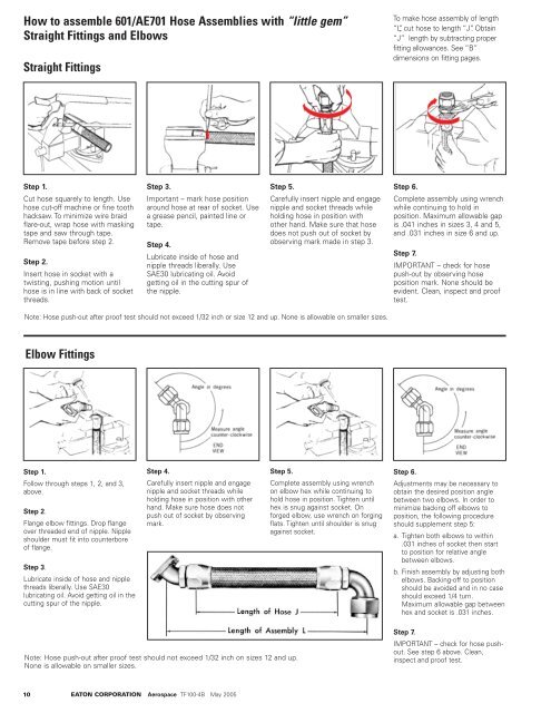
How to assemble 601/AE701 <strong>Hose</strong> Assemblies with “little gem”<br />
Straight Fittings and Elbows<br />
Straight Fittings<br />
To make hose assembly of length<br />
“L”, cut hose to length “J”. Obtain<br />
“J” length by subtracting proper<br />
fitting allowances. See “B”<br />
dimensions on fitting pages.<br />
Step 1.<br />
Cut hose squarely to length. Use<br />
hose cut-off machine or fine tooth<br />
hacksaw. To minimize wire braid<br />
flare-out, wrap hose with masking<br />
tape and saw through tape.<br />
Remove tape before step 2.<br />
Step 2.<br />
Insert hose in socket with a<br />
twisting, pushing motion until<br />
hose is in line with back of socket<br />
threads.<br />
Step 3.<br />
Important – mark hose position<br />
around hose at rear of socket. Use<br />
a grease pencil, painted line or<br />
tape.<br />
Step 4.<br />
Lubricate inside of hose and<br />
nipple threads liberally. Use<br />
SAE30 lubricating oil. Avoid<br />
getting oil in the cutting spur of<br />
the nipple.<br />
Step 5.<br />
Carefully insert nipple and engage<br />
nipple and socket threads while<br />
holding hose in position with<br />
other hand. Make sure that hose<br />
does not push out of socket by<br />
observing mark made in step 3.<br />
Step 6.<br />
Complete assembly using wrench<br />
while continuing to hold in<br />
position. Maximum allowable gap<br />
is .041 inches in sizes 3, 4 and 5,<br />
and .031 inches in size 6 and up.<br />
Step 7.<br />
IMPORTANT – check for hose<br />
push-out by observing hose<br />
position mark. None should be<br />
evident. Clean, inspect and proof<br />
test.<br />
Note: <strong>Hose</strong> push-out after proof test should not exceed 1/32 inch or size 12 and up. None is allowable on smaller sizes.<br />
Elbow Fittings<br />
Step 1.<br />
Follow through steps 1, 2, and 3,<br />
above.<br />
Step 2.<br />
Flange elbow fittings. Drop flange<br />
over threaded end of nipple. Nipple<br />
shoulder must fit into counterbore<br />
of flange.<br />
Step 3.<br />
Lubricate inside of hose and nipple<br />
threads liberally. Use SAE30<br />
lubricating oil. Avoid getting oil in the<br />
cutting spur of the nipple.<br />
Step 4.<br />
Carefully insert nipple and engage<br />
nipple and socket threads while<br />
holding hose in position with other<br />
hand. Make sure hose does not<br />
push out of socket by observing<br />
mark.<br />
Step 5.<br />
Complete assembly using wrench<br />
on elbow hex while continuing to<br />
hold hose in position. Tighten until<br />
hex is snug against socket. On<br />
forged elbow, use wrench on forging<br />
flats. Tighten until shoulder is snug<br />
against socket.<br />
Step 6.<br />
Adjustments may be necessary to<br />
obtain the desired position angle<br />
between two elbows. In order to<br />
minimize backing off elbows to<br />
position, the following procedure<br />
should supplement step 5:<br />
a. Tighten both elbows to within<br />
.031 inches of socket then start<br />
to position for relative angle<br />
between elbows.<br />
b. Finish assembly by adjusting both<br />
elbows. Backing-off to position<br />
should be avoided and in no case<br />
should exceed 1/4 turn.<br />
Maximum allowable gap between<br />
hex and socket is .031 inches.<br />
Note: <strong>Hose</strong> push-out after proof test should not exceed 1/32 inch on sizes 12 and up.<br />
None is allowable on smaller sizes.<br />
Step 7.<br />
IMPORTANT – check for hose pushout.<br />
See step 6 above. Clean,<br />
inspect and proof test.<br />
10 EATON CORPORATION Aerospace <strong>TF100</strong>-<strong>4B</strong> May 2005