TF100-4B_Hose Bro_4-22-05.qxd - Herber Aircraft
TF100-4B_Hose Bro_4-22-05.qxd - Herber Aircraft
TF100-4B_Hose Bro_4-22-05.qxd - Herber Aircraft

You also want an ePaper? Increase the reach of your titles
YUMPU automatically turns print PDFs into web optimized ePapers that Google loves.
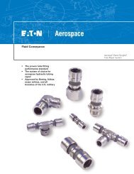
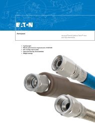
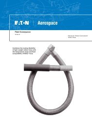
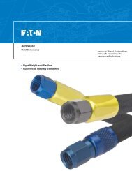
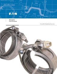
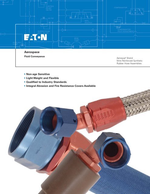
Aerospace<br />
Fluid Conveyance<br />
Aeroquip ® Brand<br />
Wire Reinforced Synthetic<br />
Rubber <strong>Hose</strong> Assemblies<br />
• Non-age Sensitive<br />
• Light Weight and Flexible<br />
• Qualified to Industry Standards<br />
• Integral Abrasion and Fire Resistance Covers Available
Aeroquip Brand Wire Reinforced Synthetic Rubber <strong>Hose</strong><br />
601/AE701 <strong>Hose</strong><br />
Construction: Synthetic rubber inner tube with two layers<br />
of stainless steel wire braid reinforcement.<br />
Application: Fuel, engine oil, and coolants.<br />
Basic Specification: MIL-H-83797, TSO C53a,<br />
Type A.<br />
AE501 <strong>Hose</strong><br />
Construction: 601/AE701 hose overlaid with a blue<br />
braided chafeguard cover of tough polyester yarn.<br />
Application: Fuel, engine oil, and coolants.<br />
Basic Specification: MIL-H-83797, TSO C53a,<br />
Type A.<br />
AE401 <strong>Hose</strong><br />
Construction: 601/AE701 hose with an integral cover of<br />
silicone rubber compound.<br />
Application: Fuel, engine oil, and coolants.<br />
Basic Specification: MIL-H-83797, TSO C53a,<br />
Type C.<br />
Integral Abrasion Resistant Cover<br />
Integral Fire Sleeve<br />
Design Features<br />
• Flexibility<br />
• Light weight<br />
• Non-age sensitive<br />
• Fluid temperatures:<br />
-65°F (-54°C) to +300°F (+149°C)<br />
• TSO C53a, Type A and Type C<br />
approvals (with fire sleeve)<br />
• Mil-Spec Approvals:<br />
• MIL-H-83796/1 through MIL-H-<br />
83796/9 Assemblies<br />
• MIL-H-83797 <strong>Hose</strong>, MIL-F-83798<br />
Fittings<br />
• Available in sizes -3 thru -32<br />
• Available with polyester/integral<br />
sleeve<br />
• Field attachable fittings<br />
NOTE: -24 and -32 hose assemblies that will be subjected to a vacuum,<br />
may require an internal support coil. Contact Eaton for additional<br />
information.<br />
End Fitting<br />
Nut: -3, -4 and -5<br />
steel, AMS 5024 (C1137)<br />
Nut: -6 and up aluminum, AMS 4119 (2024)<br />
Nut Wire: Cres., AMS5685 (305)<br />
Nipple: -3, -4 and -5<br />
steel AMS 5024 (C1137)<br />
Nipple: -6 and up aluminum, AMS4119 (2024)<br />
Elbow: -3, -4 and -5<br />
steel AMS5024<br />
(C1137); -6 and up aluminum, AMS4117 (6061)<br />
Socket: AMS4117 (6061) All sizes<br />
Thread<br />
Size Thread<br />
-3 .375-24 UNJF-3B<br />
-4 .4375-20 UNJF-3B<br />
-5 .500-20 UNJF-3B<br />
-6 .5625-18 UNJF-3B<br />
-8 .750-16 UNJF-3B<br />
-10 .875-14 UNJF-3B<br />
-12 1.0625-12 UNJ-3B<br />
-16 1.3125-12 UNJ-3B<br />
-20 1.625-12 UNJ-3B<br />
-24 1.875-12 UNJ-3B<br />
-32 2.500-12 UNJ-3B<br />
<strong>Hose</strong> Dimensions and Performance Data<br />
<strong>Hose</strong> Size -3 -4 -5 -6 -8 -10 -12 -16 -20 -24 -32<br />
601/AE701 <strong>Hose</strong> O.D. (Max.) .398 .462 .508 .571 .673 .820 .961 1.187 1.468 1.734 2.140<br />
AE501 <strong>Hose</strong> O.D. (Max.) .470 .530 .575 .659 .761 .895 1.053 1.265 1.526 1.800 2.160<br />
AE401 <strong>Hose</strong> O.D. (Max.) .721 .755 .801 .864 .966 1.112 1.253 1.465 1.726 2.019 2.436<br />
<strong>Hose</strong> I.D. (Min.) .141 .204 .266 .329 .415 .539 .665 .844 1.094 1.344 1.750<br />
Minimum Bend Radius (inches) 1.75 2.00 2.25 2.50 3.50 4.00 4.50 5.50 8.00 9.00 12.50<br />
Operating Pressure (PSI) 1500 1500 1500 1500 1250 1250 1250 1000 800 400 350<br />
Proof Pressure (PSI)3000 3000 3000 3000 2500 2500 2000 1500 1500 1300 800 600<br />
Minimum Burst Pressure (PSI) 6000 6000 6000 6000 5000 5000 4000 3000 2000 2000 1200<br />
601/AE701 <strong>Hose</strong> Wt. (Lb./Ft.) .093 .114 .145 .155 .170 .207 .285 .380 .490 .675 .903<br />
AE501 <strong>Hose</strong> Wt. (Lb./Ft.) .1<strong>22</strong> .138 .172 .184 .204 .248 .333 .439 .636 .920 1.138<br />
AE401 <strong>Hose</strong> Wt. (Lb./Ft.) .257 .310 .348 .351 .396 .474 .592 .750 .891 1.<strong>22</strong>9 1.471<br />
All dimensions in inches<br />
2<br />
EATON CORPORATION Aerospace <strong>TF100</strong>-<strong>4B</strong> May 2005
<strong>Hose</strong> Assembly Part Number Information<br />
Assembly Length<br />
Assembly length is measured from<br />
sealing surface to sealing surface.<br />
When defining the part number<br />
length, measure the length from end<br />
point to end point on flareless fittings.<br />
With elbow fittings, the measuring<br />
point is the intersection of the<br />
centerline of the elbow with the face<br />
of the sealing surface.<br />
Rotation Angle Measurement<br />
On assemblies with an elbow fitting<br />
on each end, measure the rotation<br />
angle as shown. The index angle will<br />
follow the basic style hose assembly<br />
part number indicated (see example<br />
for “double elbow” assemblies). In all<br />
cases, the angle should be<br />
expressed in 3 digits. For example,<br />
35° should be written as 035. If the<br />
angle desired is 0°, specify 000.<br />
<strong>Hose</strong> Assemblies<br />
To properly specify the correct hose<br />
assembly, use the simple numbering<br />
system below. Straight and single<br />
elbow assemblies are identified by<br />
the number beginning with AE701<br />
and double elbow assemblies are<br />
identified by a number beginning<br />
with AE70XX. Any assembly can be<br />
ordered using these numbers.<br />
Assembly Length Tolerances<br />
Up to and including 8 inches: ±.125<br />
Above 8 inches, to and including 16 inches: ±.187<br />
Above 16 inches, to and including 24 inches: ±.250<br />
Above 24 inches, to and including 36 inches: ±.312<br />
Above 36 inches, or longer: ±1%<br />
Bulk <strong>Hose</strong><br />
Bulk hose will be supplied in 25-foot lengths whenever possible, but<br />
the right is reserved to ship random lengths over 3 feet unless<br />
otherwise specified. Contact your Eaton representative if you have<br />
questions. An additional charge will be made for hose cut to specified<br />
lengths.<br />
300 ft.,601/AE701-8<br />
Length (in feet)<br />
<strong>Hose</strong> number<br />
Size (tube O.D. in 1/16’s)<br />
Straight and Single Elbow <strong>Hose</strong> Assemblies<br />
Examples<br />
Double Elbow <strong>Hose</strong> Assemblies<br />
AE701XXXX G 0184<br />
AE70XX G 0184 -035<br />
Base number for all straight<br />
and single elbow assemblies<br />
Size code (see below)<br />
Assembly length, in inches,<br />
always four digits; last digit indicates<br />
fractional length in 1/8’s of an inch<br />
<strong>Hose</strong> Dash Size 3 4 5 6 8 10 12 16 20 24 32<br />
Letter Code B E F G H J K M N P R<br />
Base number for all double<br />
elbow assemblies<br />
Size code (see below)<br />
Assembly length, in inches,<br />
always four digits; last digit indicates<br />
fractional length in1/8’s of an inch<br />
Elbow position angle, expressed in three digits<br />
EATON CORPORATION Aerospace <strong>TF100</strong>-<strong>4B</strong> May 2005<br />
3
Flared Fitting<br />
Straight 45° 90°<br />
Straight Fitting Dimensions (M83798/1-Size)<br />
Max.<br />
Max.<br />
<strong>Hose</strong> Fitting Nipple Dim. Dim. Dim. Dim. Dim. Dim. Nut Socket Fitting Dim.<br />
Size P/N P/N A B C D R* H Hex*** Hex*** Wt.** E<br />
-3 816-3 526-3 1.30 .64 .34 .64 –– .103 .58 .562 .049 ––<br />
-4 816-4 526-4 1.33 .65 .37 .70 –– .150 .65 .625 .061 ––<br />
-5 816-5 526-5 1.38 .70 .38 .76 –– .211 .72 .688 .078 ––<br />
-6 816-6D 526-6D 1.51 .76 .38 .83 –– .274 .80 .750 .046 ––<br />
-8 816-8D 526-8D 1.79 .94 .43 1.04 –– .366 1.01 .875 .078 ––<br />
-10 816-10D 526-10D 1.94 .99 .50 1.18 –– .472 1.16 1.062 .108 ––<br />
-12 816-12D 526-12D 2.01 1.00 .57 1.47 –– .576 1.45 1.188 .168 ––<br />
-16 816-16D 526-16D 2.36 1.16 .60 1.76 –– .781 1.74 1.438 .240 ––<br />
-20 816-20D 526-20D 2.64 1.34 .64 2.11 –– 1.026 2.11 1.750 .372 ––<br />
-24 816-24D 526-24D 2.79 1.44 .74 2.47 –– 1.264 2.48 1.938 .504 ––<br />
-32 816-32D 526-32D 3.16 1.62 .92 3.20 –– 1.684 3.20 2.500 .900 ––<br />
45 Degree Fitting Dimensions (M83798/2-Size)<br />
-3 8846-3 8746-3 1.74 1.05 .34 .64 .375 .103 .58 .562 .056 .376<br />
-4 8846-4 8746-4 1.72 1.02 .37 .70 .375 .150 .65 .625 .070 .352<br />
-5 8846-5 8746-5 1.83 1.12 .38 .76 .438 .211 .72 .688 .091 .415<br />
-6 8846-6D 8746-6D 2.00 1.<strong>22</strong> .38 .83 .500 .274 .80 .750 .052 .446<br />
-8 8846-8D 8746-8D 2.17 1.30 .43 .98 .500 .366 1.01 .875 .085 .457<br />
-10 8846-10D 8746-10D 2.42 1.44 .50 1.17 .625 .472 1.16 1.062 .119 .537<br />
-12 8846-12D 8746-12D 2.79 1.76 .57 1.30 .844 .576 1.45 1.188 .179 .623<br />
-16 8846-16D 8746-16D 3.06 1.83 .60 1.55 .969 .781 1.74 1.438 .255 .659<br />
-20 8846-20D 8746-20D 3.45 2.13 .64 1.91 1.188 1.026 2.11 1.750 .376 .768<br />
-24 8846-24D 8746-24D 3.65 2.28 .74 2.11 1.375 1.264 2.48 1.938 .506 .867<br />
-32 8846-32D 8746-32D 4.26 2.69 .92 2.72 1.750 1.684 3.20 2.500 .891 1.065<br />
90 Degree Fitting Dimensions (M83798/3-Size)<br />
-3 8891-3 8791-3 1.58 .89 .34 .64 .375 .103 .58 .562 .057 .752<br />
-4 8891-4 8791-4 1.59 .89 .37 .70 .375 .150 .65 .625 .071 .718<br />
-5 8891-5 8791-5 1.68 .96 .38 .76 .438 .211 .72 .688 .094 .844<br />
-6 8891-6D 8791-6D 1.85 1.07 .38 .83 .500 .274 .80 .750 .053 .9<strong>22</strong><br />
-8 8891-8D 8791-8D 2.01 1.14 .43 .98 .500 .366 1.01 .875 .088 .938<br />
-10 8891-10D 8791-10D 2.25 1.27 .50 1.17 .625 .472 1.16 1.062 .124 1.126<br />
-12 8891-12D 8791-12D 2.66 1.63 .57 1.30 .844 .576 1.45 1.188 .189 1.376<br />
-16 8891-16D 8791-16D 2.97 1.74 .60 1.55 .969 .781 1.74 1.438 .267 1.500<br />
-20 8891-20D 8791-20D 3.38 2.06 .64 1.91 1.188 1.026 2.11 1.750 .399 1.782<br />
-24 8891-24D 8791-24D 3.59 2.<strong>22</strong> .74 2.11 1.375 1.264 2.48 1.938 .538 2.032<br />
-32 8891-32D 8791-32D 4.<strong>22</strong> 2.65 .92 2.72 1.750 1.684 3.20 2.500 .953 2.532<br />
All dimensions in inches<br />
DIM. B = <strong>Hose</strong> cut factor.<br />
DIM. E = Nominal drop dimensions. Tolerance is ±.035" on bent tube fittings.<br />
*R = Radius of elbow measured to centerline.<br />
**Weight = Nipple assembly plus socket (nominal).<br />
*** = Distance across corners.<br />
Socket P/N 516-XXD<br />
4 EATON CORPORATION Aerospace <strong>TF100</strong>-<strong>4B</strong> May 2005
<strong>Hose</strong> Assembly/Swivel Flared to Swivel Flared<br />
Configurations<br />
601/AE701 AE501 AE401 601/AE701<br />
<strong>Hose</strong> <strong>Hose</strong> <strong>Hose</strong> W/AE102<br />
<strong>Hose</strong> Assembly Assembly Assembly Firesleeves<br />
Size Base No. Base No. Base No. <strong>Hose</strong> Assembly<br />
Base No.<br />
straight to straight<br />
-3 thru-32 AE7010000 AE7013110 AE7013106 AE7010001<br />
straight to 45° elbow<br />
-3 thru-32 AE7010100 AE7013111 AE7013107 AE7010101<br />
straight to 90° elbow<br />
-3 thru-32 AE7010200 AE7013112 AE7013131 AE7010201<br />
45° elbow to 45° elbow<br />
-3 thru-32 AE7000 AE7058 AE7074 AE7001<br />
45° elbow to 90° elbow<br />
-3 thru-32 AE7012 AE7059 AE7075 AE7013<br />
90° elbow to 90° elbow<br />
-3 thru-32 AE7027 AE7060 AE7076 AE7028<br />
EATON CORPORATION Aerospace <strong>TF100</strong>-<strong>4B</strong> May 2005<br />
5
Flareless Fitting<br />
Straight 45° 90°<br />
Straight Fitting Dimensions (M83798/4-Size)<br />
<strong>Hose</strong> Fitting Nipple Dim. Dim. Dim. Dim. Dim. Dim. Nut Socket Fitting Dim.<br />
Size P/N P/N A B C D R* H Hex*** Hex*** Wt.** E<br />
-3 826-3 536-3 1.52 .85 .13 .64 –– .103 .58 .640 .051 ––<br />
-4 826-4 536-4 1.48 .80 .<strong>22</strong> .70 –– .150 .654 .703 .064 ––<br />
-5 826-5 536-5 1.54 .86 .23 .76 –– .211 .72 .765 .080 ––<br />
-6 826-6D 536-6D 1.71 .96 .19 .83 –– .274 .798 .827 .048 ––<br />
-8 826-8D 536-8D 2.02 1.17 .21 1.04 –– .366 1.014 .984 .082 ––<br />
-10 826-10D 536-10D 2.<strong>22</strong> 1.26 .24 1.18 –– .472 1.158 1.171 .115 ––<br />
-12 826-12D 536-12D 2.28 1.27 .31 1.47 –– .576 1.447 1.296 .175 ––<br />
-16 826-16D 536-16D 2.64 1.44 .32 1.76 –– .781 1.736 1.546 .254 ––<br />
-20 826-20D 536-20D 2.92 1.62 .37 2.11 –– 1.026 2.111 1.906 .368 ––<br />
-24 826-24D 536-24D 3.19 1.85 .33 2.47 –– 1.264 2.477 2.109 .544 ––<br />
-32 –– –– –– –– –– –– –– –– –– –– –– ––<br />
45 Degree Fitting Dimensions (M83798/5-Size)<br />
-3 –– –– –– –– –– –– –– –– –– –– –– ––<br />
-4 880112-4 885112-4 1.72 1.1 .<strong>22</strong> .70 .25 .150 .654 .703 .070 .452<br />
-5 –– –– –– –– –– –– –– –– –– –– –– ––<br />
-6 880112-6D 885112-6D 2.03 1.36 .19 .83 .50 .274 .798 .827 .054 .578<br />
-8 880112-8D 885112-8D 2.32 1.45 .21 .98 .50 .366 1.014 .984 .088 .610<br />
-10 880112-10D 885112-10D 2.61 1.63 .24 1.17 .62 .472 1.158 1.171 .125 .725<br />
-12 880112-12D 885112-12D 2.97 1.93 .31 1.30 .84 .576 1.447 1.296 .189 .800<br />
-16 880112-16D 885112-16D 3.25 2.03 .32 1.55 .97 .781 1.736 1.546 .270 .854<br />
-20 880112-20D 885112-20D 3.65 2.33 .37 1.91 1.19 1.026 2.111 1.906 .408 .962<br />
-24 –– –– –– –– –– –– –– –– –– –– –– ––<br />
-32 –– –– –– –– –– –– –– –– –– –– –– ––<br />
90 Degree Fitting Dimensions (M83798/6-Size)<br />
-3 –– –– –– –– –– –– –– –– –– –– –– ––<br />
-4 880114-4 885114-4 1.59 .89 .<strong>22</strong> .70 .25 .150 .654 .703 .070 .860<br />
-5 880114-5 885114-5 1.68 .96 .23 .76 .31 .211 .720 .765 .071 1.000<br />
-6 880114-6D 885114-6D 1.85 1.07 .19 .83 .50 .274 .798 .827 .057 1.112<br />
-8 880114-8D 885114-8D 2.01 1.14 .21 .98 .50 .366 1.014 .984 .092 1.156<br />
-10 880114-10D 885114-10D 2.25 1.27 .24 1.17 .62 .472 1.158 1.171 .130 1.392<br />
-12 880114-12D 885114-12D 2.66 1.63 .31 1.30 .84 .576 1.447 1.296 .199 1.626<br />
-16 880114-16D 885114-16D 2.97 1.74 .32 1.55 .97 .781 1.736 1.546 .282 1.776<br />
-20 880114-20D 885114-20D 3.38 2.06 .37 1.91 1.19 1.026 2.111 1.906 .431 2.056<br />
-24 –– –– –– –– –– –– –– –– –– –– –– ––<br />
-32 –– –– –– –– –– –– –– –– –– –– –– ––<br />
All dimensions in inches<br />
DIM. B = <strong>Hose</strong> cut factor.<br />
DIM. E = Nominal drop dimensions. Tolerance is ±.035" on bent tube fittings.<br />
*R = Radius of elbow measured to centerline.<br />
**Weight = Nipple assembly plus socket (nominal).<br />
*** = Distance across corners.<br />
Socket P/N 516-XXD<br />
6 EATON CORPORATION Aerospace <strong>TF100</strong>-<strong>4B</strong> May 2005
<strong>Hose</strong> Assembly/Swivel Flareless to Swivel Flareless<br />
Configurations<br />
601/AE701 AE501 AE401 601/AE701<br />
<strong>Hose</strong> <strong>Hose</strong> <strong>Hose</strong> w/AS1072<br />
<strong>Hose</strong> Assembly Assembly Assembly Firesleeves<br />
Size Base No. Base No. Base No. <strong>Hose</strong> Assembly<br />
Base No.<br />
straight to straight<br />
-3 thru-32 AE7010010 AE7013121 AE7013132 AE7010011<br />
straight to 45° elbow<br />
-3 thru-32 AE7010110 AE7013123 AE7013133 AE7010111<br />
straight to 90° elbow<br />
-3 thru-32 AE7010210 AE7013125 AE7013134 AE7010211<br />
45° elbow to 45° elbow<br />
-3 thru-32 AE7003 AE7066 AE7077 AE7004<br />
45° elbow to 90° elbow<br />
-3 thru-32 AE7015 AE7068 AE7078 AE7016<br />
90° elbow to 90° elbow<br />
-3 thru-32 AE7030 AE7070 AE7079 AE7031<br />
EATON CORPORATION Aerospace <strong>TF100</strong>-<strong>4B</strong> May 2005 7
Flanged Fitting<br />
Straight 45° 90°<br />
Straight Fitting Dimensions (M83798/7-Size)<br />
Max.<br />
Max.<br />
<strong>Hose</strong> Fitting Nipple Dim. Dim. Dim. Dim. Dim. Dim. Socket Fitting Dim.<br />
Size P/N P/N A B C D R* H Hex*** Wt.** E<br />
-3 –– –– –– –– –– –– –– –– –– –– ––<br />
-4 –– –– –– –– –– –– –– –– –– –– ––<br />
-5 –– –– –– –– –– –– –– –– –– –– ––<br />
-6 –– –– –– –– –– –– –– –– –– –– ––<br />
-8 8844-8D 8714-8D 1.97 .84 –– .980 –– .355 .875 .089 ––<br />
-10 8844-10D 8714-10D 2.08 .87 –– 1.170 –– .472 1.062 .114 ––<br />
-12 8844-12D 8714-12D 2.29 1.25 –– 1.296 –– .576 1.188 .153 ––<br />
-16 8844-16D 8714-16D 2.53 1.30 –– 1.546 –– .781 1.438 .206 ––<br />
-20 8844-20D 8714-20D 2.83 1.50 –– 1.906 –– 1.026 1.750 .316 ––<br />
-24 8844-24D 8714-24D 2.71 1.34 –– 2.109 –– 1.264 1.938 .364 ––<br />
-32 8844-32D 8714-32D 3.08 1.52 –– 2.718 –– 1.684 2.500 .646 ––<br />
45 Degree Fitting Dimensions (M83798/5-Size)<br />
-3 –– –– –– –– –– –– –– –– –– –– ––<br />
-4 –– –– –– –– –– –– –– –– –– –– ––<br />
-5 –– –– –– –– –– –– –– –– –– –– ––<br />
-6 –– –– –– –– –– –– –– –– –– –– ––<br />
-8 8845-8D 8745-8D .208 1.18 –– .980 .500 .360 .875 .088 .338<br />
-10 8845-10D 8745-10D .<strong>22</strong>6 1.28 –– 1.170 .625 .472 1.063 .113 .375<br />
-12 8845-12D 8745-12D 2.64 1.60 –– 1.296 .844 .576 1.188 .157 .468<br />
-16 8845-16D 8745-16D 2.90 1.68 –– 1.546 .969 .781 1.438 .208 .505<br />
-20 8845-20D 8745-20D 3.25 1.93 –– 1.906 1.188 1.026 1.750 .321 .569<br />
-24 8845-24D 8745-24D 3.40 2.03 –– 2.109 1.375 1.264 1.938 .386 .625<br />
-32 8845-32D 8745-32D 3.92 2.36 –– 2.718 1.750 1.684 2.500 .672 .734<br />
90 Degree Fitting Dimensions (M83798/9-Size)<br />
-3 –– –– –– –– –– –– –– –– –– –– ––<br />
-4 –– –– –– –– –– –– –– –– –– –– ––<br />
-5 –– –– –– –– –– –– –– –– –– –– ––<br />
-6 –– –– –– –– –– –– –– –– –– –– ––<br />
-8 8890-8D 8790-8D 2.35 1.48 –– .980 .500 .360 .875 .097 .892<br />
-10 8890-10D 8790-10D 2.51 1.53 –– 1.170 .625 .484 1.063 1.123 .896<br />
-12 8890-12D 8790-12D 2.66 1.63 –– 1.296 .844 .576 1.188 .164 1.156<br />
-16 8890-16D 8790-16D 2.97 1.74 –– 1.546 .969 .781 1.438 .<strong>22</strong>2 1.282<br />
-20 8890-20D 8790-20D 3.38 2.06 –– 1.906 1.188 1.026 1.750 .344 1.500<br />
-24 8890-24D 8790-24D 3.54 2.<strong>22</strong> –– 2.109 1.375 1.264 1.938 .448 1.688<br />
-32 8890-32D 8790-32D 4.21 2.65 –– 2.718 1.750 1.684 2.500 .732 2.062<br />
All dimensions in inches<br />
DIM. B = <strong>Hose</strong> cut factor.<br />
DIM. E = Nominal drop dimensions. Tolerance is ±.035" on bent tube fittings.<br />
*R = Radius of elbow measured to centerline.<br />
**Weight = Nipple assembly plus socket (nominal).<br />
*** = Distance across corners.<br />
Socket P/N 516-XXD<br />
8 EATON CORPORATION Aerospace <strong>TF100</strong>-<strong>4B</strong> May 2005
<strong>Hose</strong> Assembly/4-Hole Flange to 4-Hole Flange<br />
Configurations<br />
601/AE701<br />
601/AE701<br />
<strong>Hose</strong><br />
w/AS1072<br />
<strong>Hose</strong> Assembly Firesleeves<br />
Size Base No. <strong>Hose</strong> Assembly<br />
Base No.<br />
straight to straight<br />
-8 thru-32 AE7010020 AE7010021<br />
straight to 45° elbow<br />
-8 thru-32 AE7010120 AE7010121<br />
straight to 90° elbow<br />
-8 thru-32 AE7010<strong>22</strong>0 AE7010<strong>22</strong>1<br />
45° elbow to 45° elbow<br />
-8 thru-32 AE7006 AE7007<br />
45° elbow to 90° elbow<br />
-8 thru-32 AE7018 AE7019<br />
90° elbow to 90° elbow<br />
-8 thru-32 AE7033 AE7034<br />
EATON CORPORATION Aerospace <strong>TF100</strong>-<strong>4B</strong> May 2005 9
How to assemble 601/AE701 <strong>Hose</strong> Assemblies with “little gem”<br />
Straight Fittings and Elbows<br />
Straight Fittings<br />
To make hose assembly of length<br />
“L”, cut hose to length “J”. Obtain<br />
“J” length by subtracting proper<br />
fitting allowances. See “B”<br />
dimensions on fitting pages.<br />
Step 1.<br />
Cut hose squarely to length. Use<br />
hose cut-off machine or fine tooth<br />
hacksaw. To minimize wire braid<br />
flare-out, wrap hose with masking<br />
tape and saw through tape.<br />
Remove tape before step 2.<br />
Step 2.<br />
Insert hose in socket with a<br />
twisting, pushing motion until<br />
hose is in line with back of socket<br />
threads.<br />
Step 3.<br />
Important – mark hose position<br />
around hose at rear of socket. Use<br />
a grease pencil, painted line or<br />
tape.<br />
Step 4.<br />
Lubricate inside of hose and<br />
nipple threads liberally. Use<br />
SAE30 lubricating oil. Avoid<br />
getting oil in the cutting spur of<br />
the nipple.<br />
Step 5.<br />
Carefully insert nipple and engage<br />
nipple and socket threads while<br />
holding hose in position with<br />
other hand. Make sure that hose<br />
does not push out of socket by<br />
observing mark made in step 3.<br />
Step 6.<br />
Complete assembly using wrench<br />
while continuing to hold in<br />
position. Maximum allowable gap<br />
is .041 inches in sizes 3, 4 and 5,<br />
and .031 inches in size 6 and up.<br />
Step 7.<br />
IMPORTANT – check for hose<br />
push-out by observing hose<br />
position mark. None should be<br />
evident. Clean, inspect and proof<br />
test.<br />
Note: <strong>Hose</strong> push-out after proof test should not exceed 1/32 inch or size 12 and up. None is allowable on smaller sizes.<br />
Elbow Fittings<br />
Step 1.<br />
Follow through steps 1, 2, and 3,<br />
above.<br />
Step 2.<br />
Flange elbow fittings. Drop flange<br />
over threaded end of nipple. Nipple<br />
shoulder must fit into counterbore<br />
of flange.<br />
Step 3.<br />
Lubricate inside of hose and nipple<br />
threads liberally. Use SAE30<br />
lubricating oil. Avoid getting oil in the<br />
cutting spur of the nipple.<br />
Step 4.<br />
Carefully insert nipple and engage<br />
nipple and socket threads while<br />
holding hose in position with other<br />
hand. Make sure hose does not<br />
push out of socket by observing<br />
mark.<br />
Step 5.<br />
Complete assembly using wrench<br />
on elbow hex while continuing to<br />
hold hose in position. Tighten until<br />
hex is snug against socket. On<br />
forged elbow, use wrench on forging<br />
flats. Tighten until shoulder is snug<br />
against socket.<br />
Step 6.<br />
Adjustments may be necessary to<br />
obtain the desired position angle<br />
between two elbows. In order to<br />
minimize backing off elbows to<br />
position, the following procedure<br />
should supplement step 5:<br />
a. Tighten both elbows to within<br />
.031 inches of socket then start<br />
to position for relative angle<br />
between elbows.<br />
b. Finish assembly by adjusting both<br />
elbows. Backing-off to position<br />
should be avoided and in no case<br />
should exceed 1/4 turn.<br />
Maximum allowable gap between<br />
hex and socket is .031 inches.<br />
Note: <strong>Hose</strong> push-out after proof test should not exceed 1/32 inch on sizes 12 and up.<br />
None is allowable on smaller sizes.<br />
Step 7.<br />
IMPORTANT – check for hose pushout.<br />
See step 6 above. Clean,<br />
inspect and proof test.<br />
10 EATON CORPORATION Aerospace <strong>TF100</strong>-<strong>4B</strong> May 2005
Testing and storage of flexible hose lines<br />
Shield<br />
Clean Inspect Proof Test/Fluid<br />
Clean, Inspect, Proof Test<br />
CLEAN…Clean hose after cutting<br />
to length. Be sure all cutting<br />
residue is dislodged. After<br />
assembly, clean each hose<br />
assembly internally using clean,<br />
dry compressed air.<br />
INSPECT…Examine hose<br />
assembly internally for cut or<br />
bulged inner tube, obstructions and<br />
cleanliness. Examine Aeroquip<br />
hose assemblies with “little gem”<br />
fittings for hose push-out. Inspect<br />
for proper gap between nut and<br />
socket or hex and socket. Nuts<br />
should swivel freely.<br />
PROOF TEST…Test hose<br />
assemblies in straight, horizontal<br />
position and observe for evidence<br />
of leakage while maintaining test<br />
pressure. Several hose assemblies<br />
may be tested at one time by<br />
connecting them in series.<br />
1. LIQUID TEST MEDIUM…<br />
tighten cap only after all<br />
trapped air has bled from<br />
assembly. Use a heavy plastic<br />
protective cover when applying<br />
pressure.<br />
2. Use proper proof-test fluid<br />
specified for hose:<br />
3. Drain and cap.<br />
4. Corrosion protection of fittings<br />
on hose assemblies.<br />
a Brass, corrosion resistant<br />
steel, and aluminum alloy<br />
fittings require no additonal<br />
treatment.<br />
b Fittings on air or instrument<br />
hose assemblies should not<br />
be oiled. Dry thoroughly and<br />
cap with oil and grease-free<br />
caps.<br />
Storage and Handling<br />
1. BULK HOSE AND HOSE<br />
ASSEMBLIES…hose should be<br />
stored away from sunlight,<br />
heat, ozone, etc. To minimize<br />
obsolescence or deterioration<br />
of hose in storage, follow<br />
“first-in, first-out” principle in<br />
releasing stock for production<br />
or shipment.<br />
2. Short hose lengths or<br />
assemblies may be<br />
conveniently stored in closed<br />
containers to protect from dust.<br />
Other hose assemblies should<br />
have the ends capped. <strong>Hose</strong><br />
assemblies made up in the field<br />
should be marked with the<br />
date of assembly before being<br />
placed in storage.<br />
NOTE: All hose assemblies taken<br />
from storage should be prooftested<br />
prior to installation in<br />
aircraft.<br />
Type <strong>Hose</strong> No. Proof Test Fluid<br />
Pneumatic<br />
Hydraulic oil<br />
fuel, oil and coolant 601/AE701 (MIL-H-5606)* or<br />
water<br />
*Flush after proof-testing using oleum or other neutral spirits.<br />
! WARNING<br />
FAILURE OR IMPROPER<br />
SELECTION,USE, OR ASSEMBLY<br />
OF THE PRODUCTS AND<br />
COMPONENTS FOR APPLICATIONS<br />
DESCRIBED HEREIN CAN RESULT<br />
IN POSSIBLE PROPERTY DAMAGE,<br />
PERSONAL INJURY OR DEATH.<br />
This document and any other related<br />
information from Eaton ® Aeroquip ®<br />
or its affiliates and authorized<br />
distributors, provide product options<br />
for consideration by Users having<br />
technical expertise with these<br />
products. Due to the wide variety of<br />
applications and operating conditions<br />
for these products and components,<br />
the User is solely responsible for<br />
making the final selection of the<br />
products and ensuring that all<br />
performance, safety and warning<br />
requirements for the User's<br />
intended application are met.<br />
Eaton Aeroquip recommends that<br />
Eaton ® Aeroquip ® hose, fittings or<br />
assembly equipment must be used<br />
only with other Eaton ® Aeroquip ®<br />
hose, fittings or assembly<br />
equipment,and Eaton Aeroquip<br />
and/or its affiliates disclaim any<br />
obligation or liability (including all<br />
incidental and consequential<br />
damages)to the extent Eaton ®<br />
Aeroquip ® hose, fittings or assembly<br />
equipment is used with any other<br />
manufacturer's hose, fittings or<br />
assembly equipment or in the event<br />
that Eaton Aeroquip recommended<br />
processes and product instructions<br />
for hose assemblies are not<br />
followed.<br />
The products described herein,<br />
including product features,<br />
specifications, designs, and<br />
availability are subject to change at<br />
any time without notice.<br />
The Company retains the right to amend, change or modify any data in this document at any time.<br />
EATON CORPORATION Aerospace <strong>TF100</strong>-<strong>4B</strong> May 2005 11
Eaton LTD<br />
Fluid Conveyance<br />
Posttach 1026<br />
Carl -Benz-Strasse 9<br />
D-8<strong>22</strong>05 Gilching<br />
Germany<br />
Phone: (49) 810-575-0<br />
Fax: (49) 810-575-27<br />
www.aerospace.eaton.com<br />
Eaton LTD<br />
Fluid Conveyance<br />
Chemin De Pau<br />
64121 Serres-Castet<br />
France<br />
Phone: (33) 559-333-864<br />
Fax: (33) 559-333-865<br />
www.aerospace.eaton.com<br />
Eaton Corporation<br />
Fluid Conveyance<br />
300 South East Avenue<br />
Jackson, Michigan 49203-1972<br />
Phone: (517) 787-8121<br />
Fax: (517) 787-5758<br />
www.aerospace.eaton.com<br />
Eaton Corporation<br />
Fluid Conveyance<br />
Meadowbrook Road<br />
P.O. Box 819<br />
Toccoa, Georgia 30577-0819<br />
Phone: (706) 779-3351<br />
Fax: (706) 779-2638<br />
www.aerospace.eaton.com<br />
Eaton Corporation<br />
Fluid Conveyance<br />
2500 W. Argyle St.<br />
P.O. Box 1845<br />
Jackson, MI 49202-1845<br />
Phone: (517) 787-8121<br />
Fax: (517) 789-4716<br />
www.aerospace.eaton.com<br />
Eaton LTD<br />
Fluid Conveyance<br />
<strong>Bro</strong>ad Ground Road<br />
Lakeside<br />
Redditch<br />
Worcs B98 8YS<br />
England<br />
Phone: (44) 152-751-7555<br />
Fax: (44) 152-751-7556<br />
www.aerospace.eaton.com<br />
©2005 Eaton Corporation<br />
All Rights Reserved<br />
Printed In USA<br />
Copying or Editing is Forbidden<br />
Form No. <strong>TF100</strong>-<strong>4B</strong><br />
May 2005