WCAP-17100-NP Rev. 1 PRA Model - Public Access Portal
WCAP-17100-NP Rev. 1 PRA Model - Public Access Portal
WCAP-17100-NP Rev. 1 PRA Model - Public Access Portal

Create successful ePaper yourself
Turn your PDF publications into a flip-book with our unique Google optimized e-Paper software.
Westinghouse Non-Proprietary Class 3<br />
<strong>WCAP</strong>-<strong>17100</strong>-<strong>NP</strong><br />
<strong>Rev</strong>ision 1<br />
Feb)ruary 2010<br />
<strong>PRA</strong> <strong>Model</strong><br />
for the<br />
Westinghouse<br />
Shut Down Seal<br />
N)Westinghouse
WESTINGHOUSE NON-PROPRIETARY CLASS 3<br />
<strong>WCAP</strong>-<strong>17100</strong>-<strong>NP</strong><br />
<strong>Rev</strong>ision 1<br />
<strong>PRA</strong> <strong>Model</strong><br />
for the<br />
Westinghouse Shut Down Seal<br />
Robert J. Lutz, Jr. *<br />
Risk Applications and Methods I<br />
Judy Hodgson *<br />
Bruce Howard *<br />
Rotating Equipment Services<br />
February 2010<br />
Approved:<br />
Duane Olinski*, Acting Manager<br />
Risk Applications and Methods I<br />
Approved:<br />
Brad Kunkel*, Manager<br />
Rotating Equipment Services<br />
Work Performed under PA-RMSC-0499<br />
*Electronically approved records are authenticated in the electronic document management<br />
system.<br />
Westinghouse Electric Company LLC<br />
P.O. Box 355<br />
Pittsburgh, PA 15230-0355<br />
© 2010 Westinghouse Electric Company LLC<br />
All Rights Reserved
Westinghouse Non-Proprietary Class 3<br />
i<br />
LEGAL NOTICE<br />
This report was prepared as an account of work performed by Westinghouse Electric Company LLC.<br />
Neither Westinghouse Electric Company LLC, nor any person acting on its behalf:<br />
A. Makes any warranty or representation, express or implied including the warranties of fitness<br />
for a particular purpose or merchantability, with respect to the accuracy, completeness, or<br />
usefulness of the information contained in this report, or that the use of any information,<br />
apparatus, method, or process disclosed in this report may not infringe privately owned<br />
rights; or<br />
B. Assumes any liabilities with respect to the use of, or for damages resulting from the use of,<br />
any information, apparatus, method, or process disclosed in this report.<br />
COPYRIGHT NOTICE<br />
This report has been prepared by Westinghouse Electric Company LLC and bears a<br />
Westinghouse Electric Company copyright notice. As a member of the PWR Owners Group, you are<br />
permitted to copy and redistribute all or portions of the report within your organization; however all<br />
copies made by you must include the copyright notice in all instances.<br />
DISTRIBUTION NOTICE<br />
This report was prepared for the PWR Owners Group. This Distribution Notice is intended to<br />
establish guidance for access to this information. This report (including proprietary and nonproprietary<br />
versions) is not to be provided to any individual or organization outside of the PWR<br />
Owners Group program participants without prior written approval of the PWR Owners Group<br />
Program Management Office. However, prior written approval is not required for program participants<br />
to provide copies of Class 3 Non Proprietary reports to third parties that are supporting<br />
implementation at their plant, and for submittals to the NRC.<br />
<strong>WCAP</strong>-<strong>17100</strong>-<strong>NP</strong>, <strong>Rev</strong>. 1 February 2010
Westinghouse Non-Proprietary Class 3<br />
Hi<br />
PWR Owners Group<br />
Member Participation* for PA-RMSC-0499<br />
Utility Member Plant Site(s) Participant<br />
Yes No<br />
AmerenUE Callaway (W) X<br />
American Electric Power D.C. Cook 1&2 (W) X<br />
Arizona <strong>Public</strong> Service Palo Verde Unit 1, 2, & 3 (CE) X<br />
Constellation Energy Group Calvert Cliffs I & 2 (CE) X<br />
Constellation Energy Group Ginna (W) X<br />
Dominion Connecticut Millstone 2 (CE) X<br />
Dominion Connecticut Millstone 3 (W) X<br />
Dominion Kewaunee Kewaunee (W) X<br />
Dominion VA North Anna I & 2, Surry I & 2 (W) X<br />
Duke Energy Catawba I & 2, McGuire I & 2 (W) X<br />
Duke Energy Oconee 1, 2, 3 (B&W) X<br />
Entergy Palisades (CE) X<br />
Entergy Nuclear Northeast Indian Point 2 & 3 (W) X<br />
Entergy Operations SouthArassI(<br />
Arkansas 2, Waterford 3 (CE),<br />
Arkansas I (B&W)<br />
W)___<br />
X<br />
Exelon Generation Co. LLC Braidwood I & 2, Byron I & 2 (W), X<br />
TMI 1 (B&W)<br />
FirstEnergy Nuclear Operating Co Beaver Valley I & 2 (W) X<br />
Davis-Besse (B&W)<br />
X<br />
Florida Power & Light Group St. Lucie I & 2 (CE) X<br />
Florida Power & Light Group Turkey Point 3 & 4, Seabrook (W) X<br />
Florida Power & Light Group Pt. Beach l&2 (W) X<br />
Luminant Power Comanche Peak I & 2 (W) X<br />
Xcel Energy Prairie Island 1 &2 (W) X<br />
Omaha <strong>Public</strong> Power District Fort Calhoun (CE) X<br />
Pacific Gas & Electric Diablo Canyon I & 2 (W) X<br />
Progress Energy Robinson 2, Shearon Harris (W), X<br />
Crystal River 3 (B&W)<br />
X<br />
PSEG - Nuclear Salem I & 2 (W) X<br />
Southern California Edison SONGS 2 & 3 (CE) X<br />
South Carolina Electric & Gas V.C. Summer (W) X<br />
So. Texas Project Nuclear Operating Co. South Texas Project I & 2 (W) X<br />
Southern Nuclear Operating Co. Farley I & 2, Vogtle I & 2 (W) X<br />
Tennessee Valley Authority Sequoyah I & 2, Watts Bar (W) X<br />
Wolf Creek Nuclear Operating Co. Wolf Creek (W) X<br />
Project participants as of the date the final deliverable was completed. On occasion, additional<br />
members will join a project. Please contact the PWR Owners Group Program Management<br />
Office to verify participation before sending this document to participants not listed above.<br />
<strong>WCAP</strong>-<strong>17100</strong>-<strong>NP</strong>, <strong>Rev</strong>. 1 February 2010
Westinghouse Non-Proprietary Class 3<br />
iii<br />
PWR Owners Group<br />
International Member Participation* for PA-RMSC-0499<br />
Utility Member Plant Site(s) Participant<br />
Yes No<br />
British Energy Sizewell B X<br />
Electrabel (Belgian Utilities) Doel 1, 2 & 4, Tihange I & 3 X<br />
Hokkaido Tomari I & 2 (MHI) X<br />
Japan Atomic Power Company Tsuruga 2 (MHI) X<br />
Kansai Electric Co., LTD Mihama I, 2 & 3, Ohi 1, 2,3 & 4,<br />
Takahamna 1, 2, 3 &4 (W & MHI)<br />
X<br />
Korea Hydro & Nuclear Power Corp.<br />
Koril, 2,3&4<br />
X<br />
Yonggwng, & (<br />
Yonggwang I & 2 (W)<br />
Korea Hydro & Nuclear Power Corp. Yonggwang 3, 4, 5 & 6 X<br />
Ulchin 3, 4, 5 & 6(CE)<br />
Kyushu Genkai 1, 2, 3 & 4, Sendai I & 2 (MHI) X<br />
Nuklearna Electrarna KRSKO Krsko (W) X<br />
Nordostschweizerische Kraftwerke AG Beznau I & 2 (W) X<br />
(NOK)<br />
Ringhals AB Ringhals 2, 3 & 4 (W) X<br />
Shikoku lkata 1, 2 & 3 (MHI) X<br />
Spanish Utilities Asco I & 2, Vandellos 2, X<br />
Almaraz I & 2 (W)<br />
Taiwan Power Co. Maanshan I & 2 (W) X<br />
Electricite de France 54 Units X<br />
This is a list of participants in this project as of the date the final deliverable was completed. On<br />
occasion, additional members will join a project. Please contact the PWR Owners Group<br />
Program Management Office to verify participation before sending documents to participants<br />
not listed above.<br />
<strong>WCAP</strong>-<strong>17100</strong>-<strong>NP</strong>, <strong>Rev</strong>. 1 February 2010
Westinghouse Non-Proprietary Class 3<br />
iv<br />
Executive Summary<br />
Westinghouse has developed a reactor coolant pump (RCP) Shut Down Seal (SDS) that<br />
restricts reactor coolant system (RCS) inventory losses to very small leakage rates in the<br />
event of a plant event that results in the loss of all RCP seal cooling. The SDS is a<br />
thermally actuated, passive device that is installed between the No. 1 seal and the No. 1<br />
seal leak-off line to provide a leak-tight seal in the event of a loss of all RCP seal cooling.<br />
The installation of the SDS will permit plants to respond to a wide range of events with only<br />
an Alternating Current (AC) independent auxiliary feedwater pump available. The possible<br />
events include station blackout, fires that disrupt power supplies, loss of component cooling<br />
system and loss of service water system. Because there would be negligible RCS inventory<br />
losses through the RCP seals, RCS makeup is no longer necessary to achieve a stable<br />
state with the reactor core being cooled.<br />
The current Probabilistic Risk Assessment (<strong>PRA</strong>) model for RCP seal performance is the<br />
WOG2000 model that has been reviewed and approved by the U.S. Nuclear Regulatory<br />
Commission (NRC) as a "consensus" model for use in the <strong>PRA</strong>. Risk-informed applications<br />
derived from <strong>PRA</strong> studies using the WOG2000 model have become part of the fabric of<br />
plant operation and includes daily plant configuration risk management activities, Mitigating<br />
System Performance Index (MSPI) reporting, regulatory submittals for change to the plant<br />
Technical Specifications (TS), and regulatory interactions during Significance Determination<br />
Process (SDP) proceedings.<br />
Plants installing the Westinghouse SDS will likely change their <strong>PRA</strong> to credit this enhanced<br />
safety capability. The current WOG2000 model will be supplanted by a new SDS model in<br />
the <strong>PRA</strong>. The revised <strong>PRA</strong> can then be used to modify risk-informed applications in use by<br />
the plant. In order to conserve utility and NRC resources in reviewing <strong>PRA</strong> models used for<br />
regulatory interactions, the <strong>PRA</strong> model for the SDS is being submitted to the NRC for review<br />
and approval. The actual change to the plant will require each licensee to perform a<br />
10 CFR 50.59 assessment to determine if prior NRC approval is required for installation of<br />
the SDS.<br />
The performance of the SDS has been verified by a large amount of testing and analysis to<br />
confirm that it meets very stringent design goals. The testing has included individual<br />
component tests as well as tests of the entire seal assembly under conditions that exceed<br />
those that are predicted for a station blackout event. The extensive testing allows the<br />
assignment of a statistically based <strong>PRA</strong> probability for the SDS failure to actuate and seal to<br />
very low leakage levels of less than 1 chance in one hundred. The testing has also shown<br />
that the likelihood of inadvertent actuation is extremely small and will not result in conditions<br />
adverse to safety.<br />
The <strong>PRA</strong> model developed for the SDS is based on the failure modes and effects analysis<br />
(FMEA) and the subsequent testing and analysis. The statistically based failure probability<br />
for the SDS to fail to actuate and seal to very low leakage will result in a significant decrease<br />
in core damage frequency (CDF) predicted from the <strong>PRA</strong>. The actual reduction will vary<br />
from plant to plant depending on the contribution of the RCP seals to the core damage risk<br />
metric.<br />
In addition to the reduction in the <strong>PRA</strong> risk metrics, the installation of the SDS may also<br />
permit utilities to modify their coping strategies for station blackout and fires as required by<br />
10 CFR 50.63 and Appendix R to 10 CFR 50 respectively. By eliminating a source of RCS<br />
inventory loss, the SDS may also have beneficial effects for mitigating strategies designed<br />
<strong>WCAP</strong>-<strong>17100</strong>-<strong>NP</strong>, <strong>Rev</strong>. 1 February 2010
Westinghouse Non-Proprietary Class 3<br />
V<br />
to cope with security related events. It is proposed that plants installing the SDS can modify<br />
their design and/or licensing basis analyses for the RCP seal performance under a loss of<br />
all RCP seal cooling event by using an RCP seal leak rate of 1 gpm for the duration of the<br />
event.<br />
This report also seeks NRC review and approval of that analysis model for the SDS in<br />
design and licensing basis analyses to facilitate NRC review of these revised analyses. It is<br />
recognized that plants will be required to submit revised design basis or licensing basis<br />
analyses to the NRC for plant specific approval; the NRC acceptance of the design /<br />
licensing basis Shut Down Seal performance will facilitate those reviews.<br />
Finally, the current plant Emergency Operating Procedures (EOPs) and Abnormal Operating<br />
Procedures (AOPs) contain several steps to protect the existing RCP seals or to minimize<br />
RCS inventory losses that would no longer be necessary after the SDS is installed. The<br />
SDS eliminates concern over rapid thermal transients at the RCP seals because SDS<br />
controls leakage, not No. 1 or 2 seal; and is not sensitive to thermal shock. Also, when the<br />
SDS is actuated, RCS inventory losses through the RCP seals are minimized and therefore<br />
cooldown and depressurization of the RCS is no longer necessary to preserve RCS<br />
inventory. Thus operator response to events that result in a loss of RCP seal cooling can be<br />
enhanced by removing those procedure steps. However, the procedure steps to trip the<br />
RCPs upon a loss of RCP seal cooling remain necessary for proper functioning of the RCP<br />
seals, including the SDS. These procedure step changes will be controlled by the plant<br />
10 CFR 50.59 assessment process to determine whether NRC review and approval is<br />
required.<br />
<strong>WCAP</strong>-<strong>17100</strong>-<strong>NP</strong>, <strong>Rev</strong>. 1 February 2010
Westinghouse Non-Proprietary Class 3<br />
vi<br />
Acknowledgement<br />
The authors of this report would like to acknowledge the significant contributions of the<br />
following individuals to the development of the Shut Down Seal:<br />
Bob Mangerie, Eric Colvin and Eric Greenawalt for expert RCP seal experience and<br />
consultation during the Shut Down Seal development and testing.<br />
Josh Hartz, Rolv Hundal and George Konopka for engineering analyses and consultation<br />
during the Shut Down Seal development and testing.<br />
Dr. Alan Lebeck for expert input on seal design and behavior during the development and<br />
testing of the Shut Down Seal.<br />
<strong>WCAP</strong>-<strong>17100</strong>-<strong>NP</strong>, <strong>Rev</strong>. 1 February 2010
Westinghouse Non-Proprietary Class 3<br />
Vii<br />
TABLE OF CONTENTS<br />
Section Description Page<br />
1. INTRODUCTION AND BACKG ROUND ..................................................<br />
1<br />
1 .1 In tro d u ctio n ....................................................................<br />
1<br />
1 .2 B a c kg ro u n d ....................................................................<br />
3<br />
2. REGULATORY EVALUATIO N .........................................................<br />
11<br />
2.1 SIDS Design Basis .....................................................<br />
11<br />
2 .2 P R A M o d e l ....................................................................<br />
1 1<br />
2.3 Determ inistic <strong>Model</strong> ..............................................................<br />
12<br />
2 .4 P ro ce d u re s ....................................................................<br />
12<br />
3. TECHNICAL EVALUATION ...........................................................<br />
14<br />
3.1 Shut Down Seal Design ...........................................................<br />
14<br />
3.2 SIDS Perform ance Assessm ents ....................................................<br />
23<br />
3 .3 P R A M o d e l ....................................................................<br />
80<br />
3.4 Determ inistic <strong>Model</strong> ..............................................................<br />
89<br />
3 .5 P ro c e d u re s ....................................................................<br />
9 1<br />
4. LIM ITATIONS AND CO NDITIO NS FOR ACCEPTANCE .....................................<br />
93<br />
5. SUM MARY AND CONCLUSIO NS ......................................................<br />
94<br />
6. REFERENCES .....................................................................<br />
96<br />
APPENDIX A - OTHER IM PACTS OF SIDS ...........................................................<br />
97<br />
APPENDIX B - SUM MARY OF SIDS TESTING .........................................................<br />
101<br />
<strong>WCAP</strong>-<strong>17100</strong>-<strong>NP</strong>, <strong>Rev</strong>. 1 February 2010
Westinghouse Non-Proprietary Class 3<br />
viii<br />
LIST OF TABLES<br />
Table Description Page<br />
Table 3-1 Guide to Test Machines and Test Results ......................................................... 24<br />
Table 3-2 Failure Modes and Effects Analysis Summary ................................................... 25<br />
Table 3-3 Table of Tests on SDS in Static Test Machine ................................................... 38<br />
Table 3-4 Hour-Interval Leakage from Shut Down Seal ..................................................... 43<br />
Table 3-5 Cumulative Leakage from SDS for Each Hour Interval .......................................... 44<br />
Table 3-6 Table of Survivabilities for SDS from Weibull Analysis ....................................... 46<br />
Table 3-7 Polymer Ring Extrusion after High Temperature Testing .................................. 47<br />
Table 3-8 Regression Analysis of Polymer Extrusion Data ................................................ 47<br />
Table 3-9 Maximum Force Data for Thermal Actuator Pistons .......................................... 49<br />
Table 3-10 Actuation Tests of SDS Assembly in the Static Tester ..................................... 50<br />
Table 3-11 Actuation Temperature for Non-Irradiated Samples ............................................. 51<br />
Table 3-12 Piston Extension Testing For Irradiated Samples ........................................... 54<br />
Table 3-13 Piston Extension Testing For Control Samples .................................................... 55<br />
Table 3-14 140 Degree Therm al Piston Soak ........................................................................ 57<br />
Table 3-15 Thermal Piston Soak Test at 190'F ................................................................ 58<br />
Table 3-16 Typical Purge and Buffer Volumes for Westinghouse RCP <strong>Model</strong>s ..................... 60<br />
Table 3-17 Engineering <strong>Model</strong> for RCP Torque for Station Blackout ..................................... 61<br />
Table 3-18 Catawba RCP Coast Down ........................................................................... 62<br />
Table 3-19 Required Torque for Rotation ......................................................................... 62<br />
Table 3-20 Operator Response Margin for Tripping the RCP ........................................... 69<br />
Table 3-21 Summary of Results from Scratch Testing ....................................................... 71<br />
Table 3-22 Maximum SI vs. Sy Allowable and Fatigue Usage Ratio .................................. 74<br />
Table 3-23 Results from Post-SBO Inspection of Modified No. 1 Insert ................................. 74<br />
Table 3-24 Seism ic Test Accelerations ............................................................................... 75<br />
<strong>WCAP</strong>-<strong>17100</strong>-<strong>NP</strong>, <strong>Rev</strong>. 1 February 2010
Westinghouse Non-Proprietary Class 3<br />
ix<br />
LIST OF FIGURES<br />
Figure Description Pagge<br />
Figure 1-1 Cut-Away Of RCP Pump Showing Location Of Seal Package .............................<br />
3<br />
Figure 1-2 Westinghouse RCP Seal Diagram With Flow Paths .....................................<br />
4<br />
Figure 1-3 Simplified P&ID RCP Seal Injection Function .........................................<br />
6<br />
Figure 3-1 Cut-Away of RCP Seal Package With SDS ...........................................<br />
14<br />
Figure 3-2 Cut-Away of Shut Down Seal .....................................................<br />
15<br />
Figure 3-3 Westinghouse Shut Down Seal Static Testing Machine ..................................<br />
30<br />
Figure 3-4 RCP Dynamic Test Machine ......................................................<br />
35<br />
Figure 3-5 Westinghouse Actuator Piston Testing Machine .......................................<br />
36<br />
Figure 3-6 Westinghouse Dynamic Crud Testing Machine ........................................<br />
37<br />
Figure 3-7 Plot of Key Variables for 29-Hour Endurance Test with T > 550'F .......................<br />
40<br />
Figure 3-8 Regression Analysis Results for Polymer Extrusion ....................................<br />
48<br />
Figure 3-9 Example Effect of Radiation on Actuation Temperature ..................................<br />
53<br />
Figure 3-10 Process Capability Analysis of Thermal Actuator .....................................<br />
56<br />
Figure 3-11 Predicted and Actual Leak Rates vs. Scratch Cross-Sectional Area ...................<br />
73<br />
Figure 3-12 RCP Seal Leakage With SDS Installed .............................................<br />
81<br />
Figure 3-13 S D S Leakage P robabilities ......................................................<br />
86<br />
Figure A-1 RCP Seal LOCA Contribution To Core Damage .......................................<br />
97<br />
Figure A-2 Contributors To Core Damage for Plant X ............................................<br />
98<br />
Figure A-3 Contributors To Core Damage for Plant Y ............................................<br />
98<br />
<strong>WCAP</strong>-<strong>17100</strong>-<strong>NP</strong>, <strong>Rev</strong>. 1 February 2010
Westinghouse Non-Proprietary Class 3<br />
X<br />
Acronyms<br />
AC<br />
AOP<br />
AOT<br />
ASTM<br />
CCW<br />
CDF<br />
CFR<br />
Cp<br />
CRM<br />
CVCS<br />
DC<br />
DI<br />
EDM<br />
EOP<br />
ERG<br />
FEA<br />
FME<br />
FMEA<br />
GPM<br />
ID<br />
LOCA<br />
LSL<br />
MLE<br />
MSPI<br />
NRC<br />
NSSS<br />
OD<br />
<strong>PRA</strong><br />
PSIA<br />
PSIG<br />
PWR<br />
RCDT<br />
RCP<br />
RCS<br />
RHR<br />
RPM<br />
SBO<br />
SDS<br />
SDP<br />
SG<br />
Alternating Current<br />
Abnormal Operating Procedure<br />
Allowable Outage Time<br />
American Society for Testing and Materials<br />
Component Cooling Water<br />
Core Damage Frequency<br />
Code of Federal Regulations<br />
Capacity Index<br />
Configuration Risk Management<br />
Chemical and Volume Control System<br />
Direct Current<br />
De-lonized<br />
Electrical Discharge Machining<br />
Emergency Operating Procedure<br />
Emergency Response Guidelines<br />
Finite Element Analysis<br />
Foreign Material Exclusion<br />
Failure Modes and Effects Analysis<br />
Gallons Per Minute<br />
Inner Diameter<br />
Loss of Coolant Accident<br />
Lower Specification Limit<br />
Maximum Likelihood Estimate<br />
Mitigating System Performance Index<br />
Nuclear Regulatory Commission<br />
Nuclear Steam Supply System<br />
Outer Diameter<br />
Probabilistic Risk Assessment<br />
Pounds Per Square Inch Absolute<br />
Pounds Per Square Inch Gauge<br />
Pressurized Water Reactor<br />
Reactor Coolant Drain Tank<br />
Reactor Coolant Pump<br />
Reactor Coolant System<br />
Residual Heat Removal<br />
<strong>Rev</strong>olutions per Minute<br />
Station Blackout<br />
Shut Down Seal<br />
Significance Determination Process<br />
Steam Generator<br />
<strong>WCAP</strong>-<strong>17100</strong>-<strong>NP</strong>, <strong>Rev</strong>. 1 February 2010
Westinghouse Non-Proprietary Class Westinghouse Non-Proprietary Class 3<br />
xi<br />
xi<br />
Acronyms<br />
SI<br />
STI<br />
SW<br />
TB<br />
TBHx<br />
TS<br />
USL<br />
VCT<br />
WPS<br />
Stress Intensity<br />
Surveillance Test Interval<br />
Service Water<br />
Thermal Barrier<br />
Thermal Barrier Heat Exchanger<br />
Technical Specifications<br />
Upper Specification Limit<br />
Volume Control Tank<br />
Waste Processing System<br />
<strong>WCAP</strong>-<strong>17100</strong>-<strong>NP</strong>, <strong>Rev</strong>. 1 February 2010
Westinghouse Non-Proprietary Class 3<br />
I<br />
I .<br />
INTRODUCTION AND BACKGROUND<br />
1.1 INTRODUCTION<br />
The Westinghouse reactor coolant pump (RCP) circulates reactor coolant fluid between the<br />
reactor core and the steam generators during normal operation to transfer heat generated in<br />
the core to the steam generators. During off-normal and accident conditions, the RCP may<br />
continue to run to provide forced circulation between the core and steam generators for<br />
enhanced decay heat removal. As long as cooling is provided to the RCP seals, the seals<br />
function normally and reactor coolant system (RCS) inventory losses are at the pre-event<br />
seal leak-off rate (nominally 3 gpm) which is within normal RCS makeup capability. Cooling<br />
to the RCP seals is provided by seal injection with thermal barrier cooling available as<br />
backup (thermal barrier only cools if seal injection fails). Operation of either means alone is<br />
sufficient to provide seal cooling.<br />
If all seal cooling is lost, the leakage of reactor coolant through the RCP seals increases and<br />
is routed to the containment as described in <strong>WCAP</strong>-10541 (Reference 1). This results in a<br />
condition in which loss of RCS inventory can result in core uncovery if adequate reactor<br />
coolant makeup cannot be provided in a timely manner.<br />
For plants with Westinghouse RCPs, compliance with several of the U.S. Nuclear<br />
Regulatory Commission's (NRC) regulatory requirements is impacted by the performance of<br />
the reactor coolant pump seals when all cooling is lost. Most notable of these are the<br />
station blackout (SBO) coping strategies and the fire coping strategies. The probabilistic<br />
risk assessments (<strong>PRA</strong>s) for these plants also show that the performance of the RCP seals<br />
under loss of all seal cooling conditions is a contributor to the plant core damage frequency<br />
(CDF), both for internal hazards initiating events as well as fire initiating events. A <strong>PRA</strong><br />
model for RCP seal behavior under loss of all seal cooling conditions is provided in <strong>WCAP</strong>-<br />
15603-A (Reference 2). In many plants, the potential for the loss of all RCP seal cooling is<br />
directly tied to the performance of service water (SW) and component cooling water (CCW)<br />
since these systems provide both thermal barrier cooling as well as cooling to the charging<br />
pumps that provide RCP seal injection. The loss of all RCP seal cooling is also tied to the<br />
availability of emergency power for continued operation of the pumps providing cooling to<br />
the seals following a station blackout.<br />
The potential for the loss of all RCP seal cooling to result in a core damage condition has<br />
been highlighted in recent applications of risk technology. In particular, the Mitigating<br />
System Performance Index (MSPI) margins for service water, component cooling water and<br />
electric power are significantly impacted at some plants by the performance of the RCP<br />
seals under loss of all seal cooling scenarios. Fire <strong>PRA</strong> considerations of loss of seal<br />
cooling and multiple spurious valve operations has also highlighted the potential for RCP<br />
seal leakage under loss of all seal cooling conditions that lead to core damage.<br />
To provide a means for utilities to address potentially risk-significant events without the<br />
addition of alternative RCP seal cooling systems, Westinghouse has developed an RCP<br />
Shut Down Seal (SDS) that will limit RCS inventory losses to very low levels in the event of<br />
a loss of RCP seal cooling.<br />
The information provided in this report is intended to provide a basis for a new model for<br />
RCP seal behavior under a loss of all RCP seal cooling conditions for both design and<br />
licensing basis analyses and <strong>PRA</strong> modeling. In particular, for plants installing the<br />
Westinghouse Shut Down Seal, compliance with design basis requirements would use the<br />
model provided in this report in place of the 21 gpm per RCP leakage that has previously<br />
been assumed in station blackout and fire coping strategy assessments. In addition,<br />
<strong>WCAP</strong>-<strong>17100</strong>-<strong>NP</strong>, <strong>Rev</strong>. 1 February 2010
Westinghouse Non-Proprietary Class 3 2<br />
restoration of RCP seal cooling in these design / licensing basis analyses would no longer<br />
be restricted to prevent cold thermal shock to the RCP seals because there is no longer any<br />
cold water (e.g., cold seal injection water) passing through the RCP seal package. For<br />
utilities installing the Shut Down Seal, the model provided in this report would also replace<br />
the model described in <strong>WCAP</strong>-15603-A for <strong>PRA</strong> assessments of RCP seal performance<br />
under loss of all seal cooling conditions. Since the model in <strong>WCAP</strong>-1 5603-A was approved<br />
by the NRC as a consensus approach to modeling RCP seal performance in the <strong>PRA</strong>, the<br />
Shut Down Seal <strong>PRA</strong> model is also being submitted to the NRC for review and approval as<br />
a consensus <strong>PRA</strong> model.<br />
Information provided in the Appendix to this report on the potential impacts of the revised<br />
SDS model in current <strong>PRA</strong> risk profiles and risk-informed applications are provided for<br />
information to facilitate NRC review of this report. Also included in the Appendix is a<br />
discussion of the potential procedure changes that could be made after installation of the<br />
SDS. The procedure changes would fall under the requirements for a 10 CFR 50.59<br />
assessment to determine if prior NRC review and approval is necessary. Therefore, NRC<br />
review and approval of the information in the Appendix is not requested.<br />
<strong>WCAP</strong>-<strong>17100</strong>-<strong>NP</strong>, <strong>Rev</strong>. 1 February 2010
Westinghouse Non-Proprietary Class 3 3<br />
1.2 BACKGROUND<br />
1.2.1 Reactor Coolant Pump Seals<br />
This section provides an overview of the operation of the 3-stage seals manufactured by<br />
Westinghouse for use in RCPs. The first sub-section provides a brief overview of the design<br />
and operation of the RCP and the 3-stage seal assembly. A more complete description can<br />
be found in <strong>WCAP</strong>-10541. The second sub-section deals with seal operation under normal<br />
operating conditions. The third sub-section deals with seal operation under a loss of all RCP<br />
seal cooling scenario.<br />
1.2.1.1 RCP Design<br />
The RCP circulates -100,000 gpm through the Nuclear Steam Supply System (NSSS). It<br />
takes RCS flow from the steam generator cold side outlet and pumps it to the reactor via the<br />
cold leg. A 6000 hp motor drives the pump at 1200 RPM (900 or 1500 RPM for 50 Hz<br />
designs). The motor is fitted with a substantial flywheel to ensure the continued pump<br />
rotation for a short period of time after pump trip, thus providing forced flow cooling of the<br />
reactor immediately after the pump is tripped.<br />
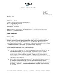
The RCP hydraulic section consists of an impeller, diffuser, casing, Thermal Barrier Heat<br />
Exchanger (TBHx), lower radial bearing, main flange, and pump shaft. There are four<br />
different RCP models used in the USA as described in <strong>WCAP</strong>-10541; all are quite similar in<br />
component pieces and performance. Figure 1-1 provides a cut-away of a <strong>Model</strong> 93A RCP.<br />
Seal<br />
Package<br />
Shaft<br />
Thermal<br />
Barrier Heat<br />
Exchanger<br />
Impeller/suction<br />
Radial<br />
Bearing<br />
Figure 1-1 Cut-Away Of RCP Pump Showing Location Of Seal Package<br />
<strong>WCAP</strong>-<strong>17100</strong>-<strong>NP</strong>, <strong>Rev</strong>. 1 February 2010
Westinghouse Non-Proprietary Class 3 4<br />
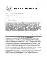
1.2.2 RCP Seal Design<br />
The seal assembly consists of three seals operating in series along the pump shaft just<br />
above the main flange. These seals reduce the RCS pressure from 2250 psia to<br />
containment ambient pressure as shown in Figure 1-2. The shaft is nominally 8 inches in<br />
diameter (7 inches for 50 Hz designs).<br />
#3 SEAL LEAKOFF<br />
#2 SEAL LEAKOFF<br />
#1 SEAL LEAKOFF -- -<br />
#1 SEAL BYPASS<br />
PUMP TYPE<br />
MODELS 93A<br />
93AS MODIFIED<br />
FOR CARTRIDGE<br />
SEAL WITHOUT<br />
#3 SEAL INJECTION<br />
E PRESSU<br />
ATMOS. 3 30<br />
93ACS41A<br />
<strong>WCAP</strong>-<strong>17100</strong>-<strong>NP</strong>, <strong>Rev</strong>. 1 February 2010
5<br />
1.2.2.1 No. 1 RCP Seal<br />
The No. 1 seal is the primary seal of the pump and is located above the lower radial bearing<br />
and constitutes the most important element of the seal package. It is a film-riding face seal.<br />
The film is produced by the system pressure drop across the seal and therefore does not<br />
require seal rotation. To maintain the film, a controlled leakage passes between the radially<br />
tapered seal faces. This leakage is radially inward toward the shaft. Because the seal ring<br />
(non-rotating faceplate which is attached to seal housing) rides on the film, it does not come<br />
in contact with the runner (rotating faceplate that is attached to the shaft). The seal ring can<br />
move axially to accommodate axial motions of the shaft. The seal inlet pressure is RCS<br />
pressure while the outlet pressure is nominally 30 psig. The pressure on the downstream<br />
side of the seal is controlled by the flow resistances in the No. 1 seal leak-off line and the<br />
volume control tank (VCT) pressure. The gap between the two seal faces is held at a<br />
constant distance by the design of the seals where the closing forces (which tend to close<br />
the gap between the runner and the ring) are equal to the opening forces of the fluid film<br />
during normal operating conditions. The sealing function is pressure dependent and does<br />
not change with shaft rotation (rotation is not required to establish the film of hydrostatic<br />
seals). The flow through the No. 1 seal gap, except for the small amount of No. 2 seal<br />
leakage, is returned to the VCT and the suction of the charging pumps.<br />
1.2.2.2 No. 2 Seal<br />
The No. 2 seal is a rubbing face seal. This seal directs the majority of the leakage from the<br />
No. 1 seal to the VCT via the No. I seal leak-off line. Leakage through the No. 2 seal is<br />
diverted to the Reactor Coolant Drain Tank (RCDT). In normal operation, the No. 2 seal<br />
operates with a differential pressure of approximately 30 psid across the face. The inlet<br />
pressure on the seal is normally determined by the VCT pressure and the back pressure is<br />
determined by the head of water maintained above the No. 2 seal leak-off connection and/or<br />
pressure in the RCDT. As a result of the very low leak rate through the No. 2 seal, the<br />
indicated leakage in the No. 1 seal leak-off line is representative of the total flow passing<br />
through the No. 1 seal.<br />
1.2.2.3 No. 3 Seal<br />
The No. 3 seal is also a rubbing face seal. This seal directs the leakage from the No.2 seal<br />
to the No. 2 seal leak-off line. The normal leakage through the No. 3 seal is measured in<br />
cubic centimeters per hour which is diverted to the radwaste system. The inlet pressure is<br />
typically 3 psig while the outlet pressure is atmospheric. There are two types of No. 3 seals<br />
in Westinghouse RCPs: a cartridge seal and a bellows seal. Both serve the same purpose<br />
although the cartridge seal is capable of withstanding significant pressure differentials<br />
compared to the bellows type seal.<br />
1.2.2.4 Non-Rotating Seals<br />
Within the seal assembly, O-rings provide sealing between components that are in static<br />
contact while a channel seal is used for locations where sliding contact occurs, between the<br />
seal rings and the seal housing inserts. The channel seal permits the ring to move axially to<br />
follow shaft motions during pump operation and maintain a constant gap in the No. 1 seal as<br />
reactor coolant system pressure and temperature change.<br />
1.2.2.5 Seal and Radial Bearing Cooling<br />
Cooling of pump components above the impeller is provided by the thermal barrier (TB), the<br />
TBHx and a seal water injection system. The TB and TBHx are located between the impeller<br />
<strong>WCAP</strong>-<strong>17100</strong>-<strong>NP</strong>, <strong>Rev</strong>. 1 February 2010
Westinghouse Non-Proprietary Class 3 6<br />
and the lower radial pump bearing while the seal injection is introduced between the TB /<br />
TBHx and the lower radial bearing, or on some plants above the radial bearing.<br />
The TB uses a set of concentric cans to limit heat transfer through the metallic pump<br />
components between the hot system water and components above the impeller. The TBHx<br />
uses CCW to cool water flowing from the RCS to the radial bearing and seal in the event of<br />
a loss of seal injection.<br />
The seal injection flow is provided by the charging pumps and enters the pump either above<br />
or below the radial bearing, depending on pump model. Injection water at slightly higher<br />
pressure than the RCS and at a flow that exceeds the No. 1 seal leak-off rate during normal<br />
operation supplies the radial bearing and seal with cool, filtered water. The injection flow not<br />
leaking past the No. 1 seal flows down past the TB and TBHx and joins the RCS circulating<br />
flow through the discharge of the pump. This flow acts as a buffer between the hot reactor<br />
coolant and the remainder of the pump. Figure 1-3 describes the interaction of the seal<br />
flows with the Chemical and Volume Control System (CVCS) and the Waste Processing<br />
System (WPS).<br />
<strong>WCAP</strong>-<strong>17100</strong>-<strong>NP</strong>, <strong>Rev</strong>. 1 February 2010
7<br />
Either cooling mode, on its own, is capable of maintaining the pump components, including<br />
the bearings and seals, in an acceptable temperature range to prevent damage during<br />
operation or beyond design basis accident conditions.<br />
Each pump is equipped with two thermocouples located in the vicinity of the lower radial<br />
bearing and the No. 1 seal to provide control room indication of the water temperatures in<br />
these areas. The exact location of these thermocouples varies with pump model. The seal<br />
temperature indications are typically through the plant computer and the alarms are also<br />
computer alarms as opposed to board annunciators.<br />
1.2.3 RCP Seal Function<br />
1.2.3.1 Normal Operation<br />
During normal operation, the seal injection system provides the RCP seal package with<br />
flush water which is required for optimal seal performance. The TB limits heat transfer from<br />
the hot RCS fluid to pump components above the impeller. The TBHx provides a redundant<br />
means of cooling the radial bearing and seals if seal injection is lost.<br />
The seal injection is provided by the charging pumps that are used to maintain RCS<br />
inventory during plant operation. Seal injection is nominally at just greater than 2250 psia<br />
and recommended to be maintained near 130 0 F, but some plants have been known to run<br />
at seal injection temperatures as high as 190 0 F. The total seal injection flow to each pump<br />
is typically 8 gpm. The amount flowing up versus down the shaft depends on the specific<br />
conditions of the installed seal. Nominal flow through the No. 1 seal is 3 gpm and can vary<br />
during the life of the seal. The normal operating range is 1 to 5 gpm.<br />
1.2.3.2 Alarms and Responses<br />
The No. 1 leak-off flow alarm settings are 1.0 gpm and 5.0 gpm with reactor and pump<br />
shutdown specified in procedures at less than 0.8 gpm or greater than 6 gpm. If the high<br />
alarm is reached (and verified that flow is high) the behavior of the radial bearing and No. 1<br />
leak-off temperature dictates the shut down response. If either temperature is trending<br />
higher and the unit is in Mode 1 or 2, the operator is to trip the reactor and stop the affected<br />
pump. If in Mode 3 or lower, the unit is permitted to operate with one less RCP without<br />
tripping the reactor; only the affected pump is stopped. If, on the other hand, the<br />
temperatures are stable or dropping, the operator is to initiate a controlled shut down to<br />
Mode 3 and should remove the RCP from service within 8 hours.<br />
The high temperature alarm settings for both the No. 1 seal leak-off and lower pump bearing<br />
is between 180°F and 190°F, depending on the pump model. If the setpoint is reached, the<br />
operator is directed to shut the pump down as soon as possible (initiate controlled shut<br />
down to Mode 3 and remove affected RCP from service).<br />
1.2.3.3 Immediate Pump Shutdown Criteria<br />
An immediate pump shutdown is required if any of the following seal-cooling-relevant<br />
setpoints are exceeded:<br />
* The No. 1 seal leak-off temperature exceeds high alarm setting WITH rising pump<br />
bearing or No. 1 seal leak-off temperatures,<br />
" The No. 1 seal leak-off temperature exceeds 225 0 F (or alternate value in the RCP<br />
Vendor Manual),<br />
* The pump bearing temperature exceeds 225 0 F (or alternate value in the RCP Vendor<br />
Manual), or<br />
* The pump No. 1 seal leak-off rate is less than 0.8 gpm or greater than 6.0 gpm.<br />
<strong>WCAP</strong>-<strong>17100</strong>-<strong>NP</strong>, <strong>Rev</strong>. 1 February 2010
Westingqhouse Non-Proprietary Class 3 8<br />
1.2.3.4 Response during a Loss of All Seal Cooling<br />
A loss of all seal cooling is defined as the coincident loss of all TBHx cooling and seal<br />
injection cooling. As discussed in Westinghouse Technical Bulletin TB-04-22, <strong>Rev</strong>ision 1,<br />
(Reference 3), proper functioning of either TBHx cooling or seal injection will maintain the<br />
seal and bearing temperatures within the acceptable range. This prevents the No. 1 seal or<br />
bearing temperatures from reaching levels that would result in a significant change in the<br />
No. 1 seal leak-off rate.<br />
1.2.3.4.1. No. 1 Seal Behavior<br />
Shortly after a loss of all seal cooling, the RCP will be tripped either by operator actions or<br />
as a result of losing normal Alternating Current (AC) power as in a station blackout. The<br />
RCP will begin a coast down and typically stops in about three minutes. Since there is no<br />
seal injection, the water flow in the pump shaft annulus region is reversed and hot reactor<br />
coolant fluid begins to flow upward toward the seal package. The water passing through the<br />
No. 1 seal would initially be the clean/cool seal injection water that was in the shaft annulus<br />
above the TBHx just prior to the loss of all seal cooling.<br />
The time between initiation of the event and the time at which the No. 1 seal is exposed to<br />
RCS fluid at cold leg temperatures depends upon the volume of clean cool water in the<br />
annulus and the No. 1 seal leak rate during normal operation. This leak rate does not<br />
change with the pump trip and coast down since the pressure and temperature of the seal<br />
environment have not changed. <strong>WCAP</strong>-10541 states that the lower internal water volume<br />
would begin to be purged within approximately 4 to 10 minutes and would be followed by an<br />
increase in seal temperature due to the in-surge of high temperature reactor coolant. The<br />
RCP seal behavior described in <strong>WCAP</strong>-15603-A, <strong>Rev</strong>ision 1, assumes that in 13 minutes<br />
following a loss of all seal cooling, the volume of the lower pump internals would be<br />
completely purged and the seal area water temperature would be approaching the 550°F<br />
RCS fluid temperature. A more accurate estimate for purge time can be calculated using<br />
the pump's actual purge volume and dividing that by the leak rate at the time of the event,<br />
per Technical Bulletin TB-04-22, <strong>Rev</strong>ision 1.<br />
As the seal inlet fluid approaches RCS cold leg temperature, the system will go through a<br />
transient where the leakage from the seal will abruptly increase, but within several minutes<br />
will attain a steady-state flow as the pump components attain thermal equilibrium with their<br />
new environment. This flow will be greater than normal operation, but nearly half that of the<br />
transient flow. This leak rate will stabilize at 21 gpm as discussed in <strong>WCAP</strong>-10541. The<br />
reason for the higher leakage is that for a low balance ratio seal, under a phase change<br />
condition across the face, the lifting force of the two-phase fluid becomes higher than that<br />
for liquid only at the same film thickness so that the seal must open to a larger gap to have<br />
an equilibrium operating point. The new steady-state conditions differ from normal operating<br />
in the following aspects, all of which tend to increase leakage:<br />
• Decrease in fluid viscosity due to temperature increase,<br />
• Transition from laminar to turbulent flow due to decreased fluid density,<br />
" Two-phase flow between seal faces resulting from flashing of hot fluid between faces,<br />
" Thermal gradients in seal assembly components, and<br />
" Change in pressure gradient across seal components.<br />
<strong>WCAP</strong>-<strong>17100</strong>-<strong>NP</strong>, <strong>Rev</strong>. 1 February 2010
Westinghouse Non-Proprietary Class 3 9<br />
1.2.3.4.2. No. 2 Seal Behavior<br />
The No. 2 seal normally operates in a rubbing face or boundary lubricated mode. However,<br />
the No. 2 seal has been deliberately designed to enter a film-riding mode when exposed to<br />
higher differential pressures, such as the predicted 800 psid differential for a loss of all seal<br />
cooling event. The No. 2 seal achieves film-riding by using pressure induced mechanical<br />
deflections to cause convergence of the normally flat parallel faces of the No. 2 seal ring<br />
and runner. This results in an increased lifting force that causes the ring to separate from<br />
the runner. The leak rate is greater in the film-riding mode because the separation between<br />
the sealing surfaces, as well as the differential pressure across the seal face, is greater.<br />
However, a high thermal gradient across the seal faces causes a divergent seal face to<br />
develop, which results in high closing loads. Thus, the No. 2 seal is expected to roll<br />
divergent and close following a loss of all seal cooling thereby limiting the leakage through<br />
the No. 1 seal to 21 gpm by maintaining a high pressure in the chamber between the No. 1<br />
and No. 2 seals.<br />
The NRC, in their Safety Evaluation on <strong>WCAP</strong>-15603-A, <strong>Rev</strong>ision 1, postulated that the<br />
No. 2 seal could pop open before the No. 2 seal faces become divergent and thus fail to<br />
provide a significant back pressure in the chamber between the No. 1 and No. 2 seal. In<br />
this case, it is estimated that the leakage through the No. 2 seal could be as high as 182<br />
gpm. It is noted that this phenomenon has not occurred in the operating history of the RCP<br />
seals, including a number of incidents of loss of all seal cooling as described in<br />
<strong>WCAP</strong>-16396-<strong>NP</strong> (Reference 4).<br />
1.2.3.4.3. No. 3 Seal Behavior<br />
The behavior of the No. 3 RCP seal only becomes important if the No. 2 seal does not<br />
remain functional during the loss of all seal cooling event. <strong>WCAP</strong>-10541 assessed the<br />
performance of the cartridge No. 3 seal, for the case of a No. 2 seal that is partially<br />
damaged or is in a film-riding mode prior to coming to thermal equilibrium. The study<br />
showed that a high thermal gradient causes a divergent seal face to develop, similar to the<br />
No. 2 seal behavior, which results in high closing loads. For this design, it was concluded<br />
that the cartridge No. 3 seal offers significant capability to limit leakage from the RCP seal<br />
package.<br />
The performance of the bellows No. 3 seal design is not discussed in <strong>WCAP</strong>-10541. The<br />
bellows design cannot be relied upon to handle significant pressure differentials.<br />
1.2.3.4.4. O-Ring Survivability<br />
The non-rotating seal components described earlier (the O-rings and channel seal) are<br />
designed and tested to assure long term survivability when in contact with hot reactor<br />
coolant fluid as described in <strong>WCAP</strong>-10541. Survivability testing of the first batch of material<br />
used for the O-rings is described in <strong>WCAP</strong>-1 0541, Supplement 1 (Reference 5). The testing<br />
regime was comprised of exposure to accident pressure and temperature for a prolonged<br />
time period followed by increasing pressure until failure occurs. The test fixture was<br />
designed to simulate the most severe possible extrusion gap for the O-rings. The lowest<br />
failure pressure of the O-rings in this batch of material was 1710 psig. As the original batch<br />
of O-ring material was used, it became necessary for a second and, more recently, a third<br />
batch of O-ring material to be procured. Subsequent testing of these later batches of O-ring<br />
materials, using the same survivability test program that was used for the first batch, shows<br />
that the lowest failure pressure was significantly higher for the last batch. This is attributed<br />
to slight changes in the O-ring material for improved high temperature extrusion resistance.<br />
<strong>WCAP</strong>-<strong>17100</strong>-<strong>NP</strong>, <strong>Rev</strong>. 1 February 2010
Westinghouse Non-Proprietary Class 3 10<br />
Therefore, the 1710 psig limitation on 0-ring survivability is considered to be no longer<br />
applicable since 0-rings from the first batch are no longer in service.<br />
0-rings for the SDS will all be manufactured from the latest third batch of 0-ring material.<br />
However, as discussed later in this report, there are only a very limited number of 0-rings<br />
that would be exposed to the high pressure differentials resulting from actuation of the SDS<br />
and in most cases, the extrusion gaps are predicted to close due to thermal expansion of<br />
the contiguous components. The one that will have an extrusion gap was tested using the<br />
process for the existing RCP 0-rings. Details are found in Section 3.2.4 of this report.<br />
1.2.3.4.5. Postulated Seal Failures<br />
The WOG2000 <strong>PRA</strong> model in <strong>WCAP</strong>-15603-A for RCP seal behavior under a loss of all seal<br />
cooling event has four basic scenarios. In the first scenario, all of the seal stages perform<br />
as designed limiting RCS inventory loss through the seal package to 21 gpm per RCP. This<br />
was assigned a probability of occurrence of 0.79. The second scenario assumes that the<br />
No. 1 seal would "bind" in an open position in spite of the closing forces on the back side of<br />
the No. 1 seal and, assuming that the No. 2 seal closed as designed, results in an RCS<br />
inventory loss of 76 gpm per RCP. This was assigned a probability of occurrence of 0.01.<br />
The third scenario assumes that the No. 1 seal behaved as designed, but that the No. 2 seal<br />
would "pop" open and result in an RCS inventory loss of 182 gpm per pump. This was<br />
assigned a probability of occurrence of 0.1975. The fourth scenario assumes that the No. 1<br />
seal "binds" open and the No. 2 seal "pops" open resulting in an RCS inventory loss of 480<br />
gpm per pump. This was assigned a probability of 0.0025. The conservatisms in the<br />
WOG2000 <strong>PRA</strong> model are discussed in <strong>WCAP</strong>-16396-<strong>NP</strong>.<br />
1.2.3.4.6. Operator Actions<br />
The generic emergency response to the loss of all AC power instructs plant operators to use<br />
natural circulation cooldown of the RCS to cool the RCP seals following restoration of AC<br />
power if the RCP seals had been exposed to hot RCS fluid, rather than restoring seal<br />
injection or TBHx cooling. This is applicable to all plants with Westinghouse seals,<br />
regardless of 0-ring material. This strategy acknowledges the uncertainty associated with<br />
the seal response to a cold thermal shock and the benefits of a decrease in RCS inventory<br />
loss as the seal leak rate decreases with decreasing RCS pressure and temperature. There<br />
is also a concern with restoration of TBHx cooling resulting in the potential loss of the CCW<br />
system integrity due to water hammer, which could result in the loss of mitigating capability<br />
for the event. The concern with restoration of seal injection was the potential for seal<br />
damage due to cold thermal shock which could increase the seal leakage rate to<br />
containment.<br />
As described in <strong>WCAP</strong>-16396-<strong>NP</strong>, there are several instances in which seal cooling has<br />
been restored following a loss of all RCP seal cooling. In each of these instances, no<br />
damage to the RCP seals that results in high levels of RCS inventory loss have been<br />
observed. However, because the restoration of RCP seal cooling has not been fully<br />
analyzed, Westinghouse recommends in Technical bulletin TB-04-22, <strong>Rev</strong>ision 1, that<br />
cooling of the seals should be done by RCS natural circulation cooldown if the seal<br />
temperature exceeded the shut down limit specified in the RCP Instruction Book (typically<br />
225 0 F to 235 0 F) rather than re-establishing seal injection. Westinghouse further<br />
recommends that following a loss of all seal cooling event, the affected RCPs be stopped<br />
immediately or at least before the seal and bearing temperatures begin to rise.<br />
<strong>WCAP</strong>-<strong>17100</strong>-<strong>NP</strong>, <strong>Rev</strong>. 1 February 2010
Westinghouse Non-Proprietary Class 3<br />
I1I<br />
2. REGULATORY EVALUATION<br />
The proposed <strong>PRA</strong> model for the Westinghouse Shut Down Seal that is presented below is<br />
based on the technical information provided in Section 3 of this report. Also a proposed<br />
model for deterministic analyses for plants installing the Westinghouse Shut Down Seal is<br />
presented, consistent with the technical assessments provided in Section 3 of this report.<br />
Finally, the impact of installation of the Shut Down Seal on plant procedures is presented in<br />
this section with further amplification in Section 3 of this report.<br />
2.1 SDS DESIGN BASIS<br />
The SDS is designed and tested to support utility compliance with various NRC<br />
requirements including 10 CFR 50.63 and 10 CFR 50.48 and Appendix R to 10 CFR 50 as<br />
well as the Probabilistic Risk Assessment (<strong>PRA</strong>) model.<br />
10 CFR 50.63 requires a utility to identify the SBO duration it must be able to withstand and<br />
recover from, and prove its ability to do so. The duration is dependent on the redundancy<br />
and reliability of on-site emergency AC power and the expected frequency and probable<br />
time needed to restore off-site power. The coping times range from 2, 4, 8, or 16 hours.<br />
Coping times for utilities using Westinghouse RCP seals typically range from 1 to 4 hours,<br />
but for conservatism, an 8-hour coping time was considered in the development to the SDS<br />
design basis.<br />
Appendix R to 10 CFR 50 requires that pressurizer level indication be maintained on-scale<br />
in the event of a fire in order to maintain control of the RCS pressure and thus provide a<br />
means to bring the reactor to safe shut down conditions. Appendix R also requires that the<br />
plant be able to maintain hot shut down conditions following a design basis fire and then<br />
achieve cold shut down within 72 hours.<br />
The <strong>PRA</strong> assessments typically require a 24-hour mission time for components that mitigate<br />
the consequences of an initiating event. No core damage is assumed to occur for an<br />
accident scenario in the <strong>PRA</strong> if the plant is in a safe stable state at 24 hours after the<br />
initiating event.<br />
2.2 <strong>PRA</strong> MODEL<br />
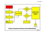
The event tree shown in Section 3 was developed to illustrate the elements of successful<br />
SDS actuation to limit RCS leakage to very low levels. This detailed model was not<br />
intended to be implemented into plant specific <strong>PRA</strong> models. Rather it was intended that a<br />
very simple event tree would be implemented directly in preceding the existing RCP seal<br />
model that asks two questions:<br />
Does the SDS effectively limit RCS inventory losses to negligible values?<br />
a,C<br />
Is the reactor coolant pump tripped prior to actuation of the SDS?<br />
For a station blackout event, the response to this question is always true because AC power<br />
is lost to the RCPs as the initiating event. For all other sequences, a human error probability<br />
needs to be determined for the operator action to trip the pump so that the SDS is actuated<br />
<strong>WCAP</strong>-<strong>17100</strong>-<strong>NP</strong>, <strong>Rev</strong>. 1 February 2010
Westinghouse Non-Proprietary Class 3 12<br />
on a stopped or slowly rotating shaft. The cues for the operator action and the typical times<br />
available to trip the pump motors can be found in Section 3.2.3.11 of this report. As<br />
discussed earlier, alternate methods to determine a more realistic time available for RCP trip<br />
can also be used.<br />
a,c<br />
2.3 DETERMINISTIC MODEL<br />
For plants installing the SDS, the design basis and licensing basis analyses can be changed<br />
based on a 1 gpm per pump leakage rate, consistent with the design basis requirements for<br />
the SDS. The use of 1 gpm per pump provides a large margin to the expected performance<br />
of the SDS and therefore added assurance for these types of analyses.<br />
a,c<br />
2.4 PROCEDURES<br />
2.4.1 Emergency Operating Procedures<br />
There are currently three limitations in the generic Westinghouse Emergency Response<br />
Guidelines (ERGs) related to the current RCP seals. The limitations are:<br />
* Restrictions on re-establishing seal injection or thermal barrier cooling if RCP seal<br />
cooling has been lost and the temperatures exceed the criteria for RCP shut down.<br />
* Restriction on cooling down the RCS following a loss of all seal cooling event to less<br />
than or equal to 100°F per hour to prevent thermal shock to the RCP seal package.<br />
* The need to cooldown and depressurize the RCS following a loss of all seal cooling<br />
event to minimize RCS inventory loss through the RCP seals and therefore maximize<br />
recovery time.<br />
Each of these limitations can remain in the generic procedures following installation of the<br />
SDS because they have no impact on the SDS performance. These limitations can be<br />
removed for RCP seal performance issues since the SDS prevents flow through the seal<br />
package when actuated and therefore the potential for RCS inventory losses and thermal<br />
shock of the seals is eliminated. However, other issues such as CCW water hammer, RCP<br />
shaft bending, bearing damage and cooldown rate limitations for other RCS components are<br />
still applicable.<br />
The Emergency and Abnormal procedure steps to stop the RCP upon loss of all seal cooling<br />
are very important to assure the survivability of the SDS.<br />
<strong>WCAP</strong>-<strong>17100</strong>-<strong>NP</strong>, <strong>Rev</strong>. 1 February 2010
Westinghouse Non-Proprietary Class 3 13<br />
2.4.2 Abnormal Operating Procedures<br />
The Abnormal Operating Procedures (AOPs) would typically provide operator guidance for<br />
fires, loss of CCW and loss of SW events that can result in a loss of RCP seal cooling.<br />
Since typical AOPs are plant specific and do not rely on a common basis similar to the<br />
ERGs, the contents may vary from plant to plant. However, the important characteristics of<br />
the AOPs can be identified as:<br />
* Rapid diagnosis of a loss of seal cooling event followed by tripping of the reactor coolant<br />
pumps based on loss of charging pump and component cooling water flow or<br />
temperatures.<br />
" Do not turn "on" oil lift" pumps to aid in natural circulation cooling of the reactor core when<br />
all RCP seal cooling is lost.<br />
2.4.3 Start-Up Procedures<br />
The plant start-up procedures provide guidance on the use of the oil lift pumps during initial<br />
RCP start from cold shut down. The oil lift pumps are used to aid in starting the RCPs and<br />
are then typically turned "off' and not used again. The start-up procedures should be<br />
reviewed to confirm that the operators are instructed to turn off the oil lift pump after the<br />
RCP is started, in accordance with the RCP vendor's Instruction Manual.<br />
<strong>WCAP</strong>-<strong>17100</strong>-<strong>NP</strong>, <strong>Rev</strong>. 1 February 2010
Westinghouse Non-Proprietary Class 3 14<br />
3. TECHNICAL EVALUATION<br />
3.1 SHUT DOWN SEAL DESIGN<br />
The Shut Down Seal is a mechanical shaft sealing system which can be installed into the<br />
existing Westinghouse RCPs between the No. 1 and No. 2 seals. The SDS is passively<br />
activated based on elevated fluid temperatures on the back side of the No. 1 RCP seal.<br />
Once this seal is activated it will limit RCP shaft leakage to significantly less than 1 gpm.<br />
The SDS is a one-time use seal and must be replaced after activation.<br />
3.1.1 Theory of Operation<br />
The RCP Shut Down Seal is located between the No. 1 and No. 2 seals, just upstream of<br />
the No. 1 seal leak-off line as shown in Figure 3-1. The seal is located in the housing of the<br />
No. 1 Insert, encircling the shaft. The No. 1 seal Insert is modified by machining out a<br />
portion of the inner diameter at the top flange. Until activated, the seal is completely<br />
contained within the space once taken by the No. 1 Insert prior to modification. Thus the<br />
annulus between the No.1 Insert and the shaft is unaltered. The leak-off through the No. 1<br />
seal is unimpeded on its way to the No. 1 seal leak-off line. The No. 1 seal leak-off flow is<br />
not affected during normal operation of the rotating equipment.<br />
-#3Seal<br />
#1 Leak<br />
Off I-<br />
Location of<br />
Sh utdowIa-<br />
Seal<br />
... #2 Seal<br />
"1 Seal<br />
Figure 3-1 Cut-Away of RCP Seal Package With SDS<br />
The Shut Down Seal is composed of an actuating device and a sandwich composed of a<br />
wave spring, a piston ring, a polymer ring and a retaining ring as shown in Figure 3-2. The<br />
actuating device holds the piston ring "open" permitting No. 1 seal leak-off to flow up the<br />
shaft to the No. 1 seal leak-off line. The polymer ring is sandwiched between the piston ring<br />
and the retaining ring. The retaining ring is shrink fitted and retains all of the SDS<br />
components. When assembled in the pump, the retaining ring is further retained in place by<br />
the RCP seal housing located directly above it. The wave ring is designed to maintain<br />
contact between the three rings.<br />
<strong>WCAP</strong>-<strong>17100</strong>-<strong>NP</strong>, <strong>Rev</strong>. 1 February 2010
Westinghouse Non-Proprietary Class 3 15<br />
When the fluid coming through the No.1 seal increases to the temperature that causes the<br />
actuator to retract the spacer from the piston ring, the piston ring snaps closed against the<br />
shaft, providing a significant flow restriction and causing the pressure to build on the back<br />
side of the polymer ring. With the flow severely restricted, the pressure at the piston ring<br />
approaches the reactor coolant system pressure which forces the polymer ring against the<br />
shaft creating a leak-tight seal.<br />
Figure 3-2 Cut-Away of Shut Down Seal<br />
3.1.1.1 Activation and Sealing Process<br />
The activating portion of the seal is made up of a retractable spacer holding the ends of a<br />
piston ring open. The retractable spacer is activated by a thermally responsive piston<br />
device.<br />
While the piston ring provides a substantial flow restriction, the primary sealing ring is a<br />
polymer material that, when acted upon by the very high pressure drop induced by the<br />
piston ring interrupting the flow through the annulus, is constricted around the shaft and<br />
upwards against a retaining ring. As the primary sealing ring constricts, it creates greater<br />
pressure drop which in turn further constricts the ring tighter around the shaft and upwards.<br />
This pressure drop also forces the piston ring and retaining ring upwards, ensuring a tight<br />
seal between all the sealing surfaces. The polymer ring can conform to pump shaft<br />
<strong>WCAP</strong>-<strong>17100</strong>-<strong>NP</strong>, <strong>Rev</strong>. 1 February 2010
Westinghouse Non-Proprietary Class 3 16<br />
out-of-roundness, scratches, dents, debris, roughness, and other surface anomalies. An<br />
advantage of the polymer is its ability to slip along the shaft axially and shift with it radially<br />
and still maintain a tight seal. This is because it is a continuous ring with a low coefficient of<br />
friction. Note the piston ring, once it initiates sealing, is no longer required for the polymer<br />
ring to seal.<br />
3.1.1.2 Primary Sealing Ring<br />
Using the polymer yields a leak-tight seal at RCS pressures and temperatures.<br />
<strong>WCAP</strong>-<strong>17100</strong>-<strong>NP</strong>, <strong>Rev</strong>. 1 February 2010
Westinghouse Non-Proprietary Class 3 17<br />
Westinghouse Non-Proprietary Class 3 17<br />
3.1.1.3 Retracting Thermal Actuator<br />
The axis of the retracting thermal actuator is perpendicularly located relative to that of the<br />
shaft and is recessed into the housing of the No. 1 Insert. It is located in a bore made in the<br />
flange of the No. 1 Insert where the inner diameter (ID) has been enlarged for the sealing<br />
rings. The retracting actuator is a spring-loaded spacer restrained by a thermal piston.<br />
]a,c<br />
I<br />
<strong>WCAP</strong>-<strong>17100</strong>-<strong>NP</strong>, <strong>Rev</strong>. 1 February 2010
Westinghouse Non-Proprietary Class 3 18<br />
3.1.1.4 Piston Ring<br />
On the majority of Westinghouse RCPs in the U.S. (<strong>Model</strong> 93A), the shaft adjacent to the<br />
insert has a sleeve used as a spacer (No. 1 Runner Retaining Sleeve). The SDS will be<br />
sealing on this sleeve rather than the shaft. The piston ring for this pump model can be a<br />
I a"c In the other RCP models (93, 93A-1, and 100), there is no sleeve. The SDS will<br />
seal directly on the shaft.<br />
The term shaft will be used henceforth to describe the cylindrical surface on which the SDS<br />
seals, but in most cases the actual surface will be a sleeve.<br />
I<br />
a,C<br />
3.1.1.5 Wave Spring<br />
]a,c<br />
The wave spring is located between the Modified No. 1 insert and the piston ring. Its<br />
purpose is to provide a slight pressure on the piston ring and polymer ring to prevent<br />
movement during normal plant operation.<br />
3.1.1.6 Retaining Ring<br />
The retaining ring is coated and lapped to a fine finish to minimize friction between it and the<br />
polymer ring to tolerate a short period of shaft coast down rotation.<br />
3.1.1.7 Modified No. 1 Insert<br />
a,c<br />
The advantage of modifying the No. 1 Insert for the Shut Down Seal housing is two-fold.<br />
One is that this is a replacement part, so retrofitting a pump with this seal only requires<br />
replacing the existing Insert with a modified one. Secondly, modifying the Insert can be<br />
done before opening the pump for access. Installation of the modified Insert, with the SDS<br />
already installed prior to shipment to the plant in order to minimize the potential for<br />
<strong>WCAP</strong>-<strong>17100</strong>-<strong>NP</strong>, <strong>Rev</strong>. 1 February 2010
Westinghouse Non-Proprietary Class 3 19<br />
installation damage, is the same as a non-modified one; so installation procedural changes<br />
are minimal.<br />
3.1.1.8 Secondary Sealing Surfaces<br />
The addition of the SDS to the Westinghouse RCP seal package necessitated a review of<br />
the secondary sealing components (0-rings), to determine any impact to the current<br />
reliability and qualification.<br />
The Westinghouse High Temperature O-rings are qualified for service in loss of seal cooling<br />
scenarios. The original qualification was completed in the late 1980's and is documented in<br />
Supplement 1 to <strong>WCAP</strong>-10541 (Reference 5). This original qualification became the basis<br />
for the Westinghouse test specification that has been used for qualification of production<br />
master batches and qualification of any new compound formulations.<br />
During normal operation the addition of the SDS does not affect the current qualification<br />
criteria for the secondary seals.<br />
a,,<br />
3.1.2 SDS Design Basis<br />
The SDS is designed and tested to support utility compliance with various NRC<br />
requirements including 10 CFR 50.63 and 10 CFR 50.48 and Appendix R to 10 CFR 50.<br />
<strong>WCAP</strong>-<strong>17100</strong>-<strong>NP</strong>, <strong>Rev</strong>. 1 February 2010
Westinghouse Non-Proprietary Class 3 20<br />
10 CFR 50.63 requires a utility to identify the SBO duration it must be able to withstand and<br />
recover from, and prove its ability to do so. The duration is dependent on the redundancy<br />
and reliability of on-site emergency AC power and the expected frequency and probable<br />
time needed to restore off-site power. The coping times range from 2, 4, 8, or 16 hours.<br />
Coping times for utilities using Westinghouse RCP seals typically range from 1 to 4 hours,<br />
but for conservatism, an 8-hour coping time was considered in the development to the SDS<br />
design basis.<br />
Appendix R to 10 CFR 50 requires that pressurizer level indication be maintained on-scale<br />
in the event of a fire in order to maintain control of the RCS pressure and thus provide a<br />
safe means to bring the reactor to safe shut down conditions. Appendix R also requires that<br />
the plant be able to maintain hot shut down conditions following a design basis fire and then<br />
achieve cold shut down within 72 hours.<br />
For consideration of coping strategies for extensive plant damage events (e.g.,<br />
10 CFR 50.54(hh)) from beyond design basis causes, no time frame is provided for the<br />
effectiveness of the coping strategies.<br />
The <strong>PRA</strong> assessments typically require a 24-hour mission time for components that mitigate<br />
the consequences of an initiating event. No core damage is assumed to occur for an<br />
accident scenario in the <strong>PRA</strong> if the plant is in a safe stable state at 24 hours after the<br />
initiating event. The 24 hours is based on an assumption that other measures can be<br />
implemented if a subsequent failure should occur.<br />
3.1.2.1 SDS Leakage Rate Design Basis<br />
For a fire scenario that interrupts RCS makeup and also results in a loss of all RCP seal<br />
cooling, a long term RCP inventory loss rate of less than 1 gpm per pump provides over<br />
2 hours for recovery of RCS makeup before pressurizer level indication is lost. Further, this<br />
low level of RCP seal leakage ensures that most RCS makeup sources can be effective in<br />
maintaining pressurizer level and transitioning to cold shut down within 72 hours.<br />
For a station blackout scenario, an RCP leakage rate of less than 1 gpm provides<br />
considerable margin to core uncovery for an 8-hour coping time.<br />
For consideration of coping strategies for fire protection, an RCP inventory loss rate of less<br />
than 1 gpm through the SDS provides over 10 hours in which to recover a source of RCS<br />
makeup.<br />
For extensive plant damage events from beyond design basis causes, an RCP inventory<br />
loss rate of less than 1 gpm through the SDS provides over 72 hours in which to recover a<br />
source of RCS makeup.<br />
For the <strong>PRA</strong>, an RCS inventory loss rate of less than 1 gpm through the RCP seals provides<br />
considerably more than 24 hours in which to recover a source of RCS makeup.<br />
These considerations assume that steam generator cooling is maintained to prevent RCS<br />
pressurization to the point where RCS inventory loss occurs through the pressurizer relief or<br />
safety valves. It is also noteworthy that RCS depressurization using the steam generators is<br />
not required in the first eight hours for either of the design bases and is not required in the<br />
first 24 hours for the <strong>PRA</strong> consideration.<br />
Thus, an SDS design basis leakage rate of less than 1 gpm per RCP seal provides<br />
significant additional protection for scenarios involving a loss of all RCP seal cooling. A<br />
more restrictive design basis leakage rate (less than 1 gpm) does not result in a substantial<br />
additional increase in safety as measured by these considerations.<br />
<strong>WCAP</strong>-<strong>17100</strong>-<strong>NP</strong>, <strong>Rev</strong>. 1 February 2010
Westinghouse Non-Proprietary Class 3<br />
3.1.2.2 SDS Temperature and Pressure Design Basis<br />
The SDS is designed to limit RCS inventory losses for plant events that involve a loss of all<br />
RCP seal cooling and decay heat is being removed by the steam generators. Without heat<br />
removal by the steam generators, the RCS would pressurize to the opening setpoint for the<br />
pressurizer relief / safety valves and rapid inventory loses would occur through the relief /<br />
safety valve. The Shut Down Seal would be of little value for these cases where RCS<br />
inventory is being lost through the pressurizer relief / safety valves. For cases with the<br />
steam generators removing decay heat via natural circulation, the RCS cold leg<br />
temperatures are expected to be in the range of 550OF as predicted by computerized<br />
simulations (Reference 1).<br />
3.1.2.3 Duration<br />
aC<br />
The longest coping time in the regulatory basis for the SDS is the 72-hour value from<br />
Appendix R to 10 CFR 50. The SDS is designed to remain leak-tight for this 72-hour time<br />
period which includes 24 hours at post-station blackout RCS system pressure and<br />
temperature followed by a rapid cooldown to normal RHR cooling (shutdown cooling) and<br />
maintaining RHR cooling conditions to 72 hours.<br />
As described above the 8-hour and 24-hour mission times for Station Blackout coping<br />
strategies and for <strong>PRA</strong> modeling fall within the fire protection 72-hour mission time value.<br />
3.1.2.4 Pump Shaft Rotation<br />
The SDS is designed to operate with the shaft rotation stopped. The first indication of a loss<br />
of all seal cooling would be annunciated alarms for loss of seal injection flow, loss of CCW<br />
flow and high CCW temperatures. An alarm for high leak-off temperature would be received<br />
later and is in the range of 180°F to 190°F which also alerts the operators to a potential loss<br />
of seal cooling. At 225 0 F to 235 0 F, the RCP instruction manual calls for tripping the reactor<br />
coolant pump motor. Upon tripping the reactor coolant pump motor, the pump will coast<br />
down and, based on operating experience discussed in a later section of this report, the<br />
shaft rotation is expected to stop approximately 200 seconds after trip. To accommodate<br />
possible slow shaft rotation after pump trip, the surface of the retaining ring is polished and<br />
chrome-plated to permit the polymer ring to grip the pump shaft but still slowly rotate against<br />
the retaining ring (piston ring also grips the shaft and rotates with the polymer ring).<br />
3.1.2.5 Response Time<br />
The response time for the SDS should be within the time frame for transition from normal<br />
No. 1 seal leak-off to increased leakage due to the loss of all seal cooling as discussed in a<br />
later section of this report. If the SDS is activated within this time frame, it will be activated<br />
against a single-phase flow of water that is passing through the No. 1 seal and will limit RCS<br />
inventory losses to very low levels. Activation at later times could result in non-negligible<br />
RCS inventory losses before the leak-tight sealing is established. Therefore, the SDS<br />
design basis response time is taken to be a time before significant increases in leakage<br />
through the No. 1 seal would occur.<br />
<strong>WCAP</strong>-<strong>17100</strong>-<strong>NP</strong>, <strong>Rev</strong>. 1 February 2010
Westinghouse Non-Proprietary Class 3 22<br />
3.1.2.6 Reliability<br />
The reliability requirements for the SDS are based on assuring that the failure to activate<br />
and limit leakage is not a dominant failure mode in the <strong>PRA</strong> and that the reliability is<br />
maximized for risk-informed applications such as MSPI. The ability of the SDS to meet the<br />
reliability goals has been demonstrated through testing and analysis of the SDS. The<br />
reliability goals include:<br />
" Very low potential for inadvertent actuation during normal operation to ensure that the<br />
initiating event frequency for inadvertent actuation does not contribute to the <strong>PRA</strong><br />
initiating event frequencies, as well as for plant asset management considerations.<br />
* Passive activation at a No. 1 seal leak-off temperature of 250OF to 290°F to ensure<br />
sufficient time for the operators to trip the RCP motors using existing procedures and<br />
guidance and to ensure that significant RCS inventory loss through the RCP seals does<br />
not occur prior to activation of the SDS.<br />
* Less than 1 gpm leakage following activation to eliminate the need for immediate<br />
manual operator actions to restore RCS makeup for Appendix R fire scenarios and<br />
station blackout scenarios.<br />
The target level of reliability for the Shut Down Seal that is demonstrated through testing<br />
and analysis is:<br />
a.C<br />
3.1.2.7 Service Life<br />
Currently the service life-limiting component in the RCP seal<br />
temperature O-ring. Currently its service life is qualified for 6<br />
investigation is underway to extend that qualification to 9 years.<br />
exceed this new life limitation.<br />
3.1.2.8 Material Selection<br />
[<br />
package is the highyears.<br />
However, an<br />
The SDS will meet or<br />
<strong>WCAP</strong>-<strong>17100</strong>-<strong>NP</strong>, <strong>Rev</strong>. 1 February 2010
Westinghouse Non-Proprietary Class 3 23<br />
Westinghouse Non-Proprietary Class 3 23<br />
axc<br />
3.2 SDS PERFORMANCE ASSESSMENTS<br />
This section describes the failure modes and effects analysis that guided the SDS analysis<br />
and testing to demonstrate the target levels of reliability.<br />
The test equipment as well as the test results are also presented in this section. A guide to<br />
the test machines and the test results is provided in Table 3-1. Note that for instances<br />
where testing is still in progress, the information will be provided in an update or addendum<br />
to this report when testing is complete.<br />
<strong>WCAP</strong>-<strong>17100</strong>-<strong>NP</strong>, <strong>Rev</strong>. 1 February 2010
Westinghouse Non-Proprietary Class 3 24<br />
Table 3-1 Guide to Test Machines and Test Results<br />
1 1 .1 I.<br />
4 4 I-<br />
4 t I<br />
4 4<br />
4 t I<br />
4 4<br />
3.2.1 Failure Modes and Effects Analysis<br />
A Failure Modes and Effects Analysis (FMEA) was performed on the SDS as detailed in<br />
Table 3-2. This was used as a basis for the test plans and design requirements. This form<br />
of analysis systematically identifies all possible scenarios in which a design will be expected<br />
to perform (shown as "Product Function" in table). For each scenario the analysis identifies<br />
the potential ways that the design can fail to meet the design intent (shown as "Potential<br />
Failure Mode" in table). For every mode of failure, its impacts are assessed ("Potential<br />
Failure Effects"). Then the existing controls and procedures (fail-safe, tests, calculations)<br />
that prevent either the cause or failure mode is identified in the column "Current Process<br />
Controls." Those with the greatest risks have follow-up actions identified as listed in "Future<br />
Controls."<br />
Each mode or effect in the FMEA is addressed in detail in this report.<br />
<strong>WCAP</strong>-<strong>17100</strong>-<strong>NP</strong>, <strong>Rev</strong>. 1 February 2010
Westinghouse Non-Proprietary Class 3 25<br />
Westinghouse Non-Proprietary Class 3 25<br />
Table 3-2 Failure Modes and Effects Analysis Summary<br />
I-<br />
Product Function Potential Failure Mlode PoJtentfial Failur Effects Potcntial Ca.'so' Curr-ent Proress Futui'e Controls<br />
I<br />
~Contfrols<br />
a,b,c<br />
4. 1<br />
4- 4<br />
<strong>WCAP</strong>-<strong>17100</strong>-<strong>NP</strong>, <strong>Rev</strong>. 1 February 2010
Westinghouse Non-Proprietary Class 3 26<br />
Table 3-2 Failure Modes and Effects Analysis Summary<br />
Product Function Potential Failure Node Potential Failure Effecrl Potential Causs CurrentlProcess Future Controls<br />
Con oo<br />
I<br />
a,b,c<br />
I t I'<br />
I 4 4<br />
-V<br />
<strong>WCAP</strong>-<strong>17100</strong>-<strong>NP</strong>, <strong>Rev</strong>. 1 February 2010
Westinghouse Non-Proprietary Class 3 27<br />
Table 3-2 Failure Modes and Effects Analysis Summary<br />
Product Functiin P otatl Fare NI odes Polur a If& Polentiailure<br />
Process Future Controls<br />
a,b,c<br />
4. 4-<br />
1- 1- 1-<br />
4 1<br />
'i 4<br />
I 4<br />
4 + 4 4<br />
<strong>WCAP</strong>-<strong>17100</strong>-<strong>NP</strong>, <strong>Rev</strong>. 1 February 2010
Westinghouse Non-Proprietary Class 3 28<br />
Table 3-2 Failure Modes and Effects Analysis Summary<br />
Proluct Function Potential Failure Mode Potlenil Failure Effects Potential Cause CurenI Process Future Controls<br />
Cointrol.<br />
a,b,c<br />
1~ I<br />
I 1- I<br />
-I<br />
<strong>WCAP</strong>-<strong>17100</strong>-<strong>NP</strong>, <strong>Rev</strong>. 1 February 2010
Westinghouse Non-Proprietary Class 3 29<br />
TahI~ ~-2 F~iiIiim ModA~ ~nd Fffpr~t~ AnaIv~i~ 5~uimmirv<br />
r<br />
Produti Function Potent ial Faoilure Mode PoteniAl Failure Effects Potential Causes Crrn Process Future Con trols<br />
Controls<br />
a,b,c<br />
<strong>WCAP</strong>-<strong>17100</strong>-<strong>NP</strong>, <strong>Rev</strong>. 1 February 2010
Westinghouse Non-Proprietary Class 3 30<br />
3.2.2 Test Equipment<br />
For research purposes, as well as to test prototype components and qualify the final SDS<br />
product, Westinghouse has built a series of testing machines and mock-ups specifically for<br />
this project. This section describes in detail these machines, their operation, and test<br />
capabilities. There are certain design details which must be understood in order to correctly<br />
interpret the test results and special emphasis is placed on these details.<br />
3.2.2.1 Static Testing Machine<br />
The static tester, shown in Figure 3-3, has been designed and built to duplicate the<br />
mechanical interface between the SDS as installed in the No. 1 Insert and the RCP seal<br />
housing.<br />
a,b,c<br />
I'<br />
a,b,c<br />
I<br />
Figure 3-3 Westinghouse Shut Down Seal Static Testing Machine<br />
<strong>WCAP</strong>-<strong>17100</strong>-<strong>NP</strong>, <strong>Rev</strong>. 1 February 2010
Westinghouse Non-Proprietary Class 3 31<br />
a,b,c<br />
3.2.2.1.1. Shut Down Seal Leak Test in Static Testing Machine<br />
I<br />
<strong>WCAP</strong>-<strong>17100</strong>-<strong>NP</strong>, <strong>Rev</strong>. 1 February 2010
Westinghouse Non-Proprietary Class 3 32<br />
3.2.2.1.2. Axial Movement Using the Static Testing Machine<br />
The purpose of axial testing is to determine the ability of the SDS to work correctly as the<br />
axial relationship between the seal and shaft slowly change as a result of asymmetric<br />
heating caused by the entrance of water at RCS temperatures. [<br />
a,b,c<br />
<strong>WCAP</strong>-<strong>17100</strong>-<strong>NP</strong>, <strong>Rev</strong>. 1 February 2010
Westinghouse Non-Proprietary Class 3 33<br />
] a,b,c<br />
3.2.2.1.3. Lateral Displacement Using the Static Testing Machine<br />
The same thermal issues that may cause an axial displacement of the sealing surface<br />
relative to the SDS may also cause lateral displacements. This could result from bending of<br />
the RCP shaft caused by asymmetric heating. [<br />
<strong>WCAP</strong>-<strong>17100</strong>-<strong>NP</strong>, <strong>Rev</strong>. 1 February 2010
Westinghouse Non-Proprietary Class 3 34<br />
a,b,c<br />
3.2.2.1.4. Sealing Surface Flaw Testing in the Static Tester<br />
To confirm that the SDS will function as designed against potentially defective surfaces, a<br />
test program was undertaken in which the SDS leak rate performance was measured when<br />
sealing against known defects.<br />
The sealing surface for the SDS in the <strong>Model</strong> 93A RCPs consists of a replaceable sleeve.<br />
The SDS will be furnished with a new sleeve whose diameter and surface finish will be<br />
precisely controlled. For all other models of pumps, sealing must occur directly against the<br />
RCP shaft. Since these pumps have been in service for many years, and have undergone<br />
numerous maintenance cycles, the sealing diameter may have some flaws and blemishes.<br />
These may have occurred as a result of tools striking the surface or they may have existed<br />
since manufacture. Prior to the SDS, these diameters were not critical surfaces and larger<br />
manufacturing tolerances were applied both to diameter and surface finish.<br />
a,b,c<br />
<strong>WCAP</strong>-<strong>17100</strong>-<strong>NP</strong>, <strong>Rev</strong>. 1 February 2010
Westinghouse Non-Proprietary Class 3 35<br />
3.2.2.2 Dynamic Testing Machine<br />
The dynamic test machine accepts RCP No. 1 faceplates and can perform a full range of<br />
pressure and flow tests from 230 psig to 2500 psig both statically and at 1200 RPM. [<br />
a,b,c<br />
.% a,b,c<br />
3.2.2.2.1. Rotation Torque Testing<br />
Figure 3-4 RCP Dynamic Test Machine<br />
A basic assumption in the design of the SDS is that the RCP will have come to a complete<br />
stop prior to, or shortly after, actuation and will remain stopped during the course of the<br />
accident. However testing was performed to determine how the seal would perform, and<br />
survive, if it inadvertently were exposed to rotation.<br />
[<br />
3.2.2.2.2. Low Speed Testing<br />
I<br />
a~bec<br />
<strong>WCAP</strong>-<strong>17100</strong>-<strong>NP</strong>, <strong>Rev</strong>. 1 February 2010
Wetnqos No-rpitr - ls 36<br />
Westinghouse Non-Proprietary Class 3 36<br />
] a,b,c<br />
3.2.2.2.3. Full Speed Testing<br />
3.2.2.3 Actuator Piston Testing Machine<br />
I<br />
a,b,c<br />
]a,b,c<br />
I- a,b,c<br />
Figure 3-5 Westinghouse Actuator Piston Testing Machine<br />
I<br />
<strong>WCAP</strong>-<strong>17100</strong>-<strong>NP</strong>, <strong>Rev</strong>. 1 February 2010
Westingqhouse Non-Proprietary Class 3 37<br />
Westinghouse Non-Proprietary Class 3 37<br />
3.2.2.4 Crud Tester<br />
An important consideration in the SDS design is the SDS endurance and corrosion<br />
resistance. A crud test machine was developed as shown in Figure 3-6. [<br />
a,b,c<br />
Ia,b,c<br />
a,b,c<br />
3.2.3 Test Results<br />
Figure 3-6 Westinghouse Dynamic Crud Testing Machine<br />
3.2.3.1 Sealing Endurance Tests<br />
The most challenging requirement the SDS must meet is the endurance test. Withstanding<br />
570°F and 2350 psia for 24 hours leaking less than 1 gpm must be demonstrated to meet<br />
the design specification. [<br />
<strong>WCAP</strong>-<strong>17100</strong>-<strong>NP</strong>, <strong>Rev</strong>. 1 February 2010
Westinghouse Non-Proprietary Class 3 38<br />
Westinghouse Non-Proprietary Class 3 38<br />
3.2.3.1.1. Test Results<br />
a,b,c<br />
Using the static testing machine, the SDS seal was tested repeatedly at full pressure and<br />
various temperatures.<br />
] a,b,c<br />
Table 3-3 Table of Tests on SDS in Static Test Machine<br />
[<br />
<strong>WCAP</strong>-<strong>17100</strong>-<strong>NP</strong>, <strong>Rev</strong>. 1 February 2010
Westinghouse Non-Proprietary Class 3 39<br />
a,b,c<br />
<strong>WCAP</strong>-<strong>17100</strong>-<strong>NP</strong>, <strong>Rev</strong>. 1 February 2010
Westinghouse Non-Proprietary Class 3 40<br />
r<br />
Figure 3-7 Plot of Key Variables for 29-Hour Endurance Test with T > 550°F<br />
a,b,c<br />
<strong>WCAP</strong>-<strong>17100</strong>-<strong>NP</strong>, <strong>Rev</strong>. 1 February 2010
Wetnqos No-rpitr Cls- 41<br />
Westinghouse Non-Proprietary Class 3 41<br />
a,b,c<br />
3.2.3.1.2. Statistical Analysis<br />
3.2.3.1.2.1. Failure to Seal to Design Criteria<br />
[<br />
<strong>WCAP</strong>-<strong>17100</strong>-<strong>NP</strong>, <strong>Rev</strong>. 1 February 2010
Westinghouse Non-Proprietary Class 3 42<br />
Westinghouse Non-Proprietary Class 3 42<br />
3.2.3.1.2.2. Failure to Remain Sealed for Event Duration<br />
I<br />
a,b,c<br />
<strong>WCAP</strong>-<strong>17100</strong>-<strong>NP</strong>, <strong>Rev</strong>. 1 February 2010
era<br />
Tab e stinghous-n<br />
No-Popieag from 3o nSa 43<br />
Westinghouse Non-Proprietary Class 3 43<br />
] a,b,c<br />
Table 3-4 Hour-interval Leakage from Shut Down Seal<br />
-) a,b,c<br />
<strong>WCAP</strong>-<strong>17100</strong>-<strong>NP</strong>, <strong>Rev</strong>. 1 February 2010
Westinghouse Non-Proprietary Class 3 44<br />
Table 3-5 Cumulative Leakage from SDS for Each Hour Interval<br />
-N a,b,c<br />
_ _ ~~~~~~ I. 1 _ _ _<br />
1 _ _ _<br />
1<br />
_ _<br />
4. + 4 4. 4.<br />
4. + 4 4. 4.<br />
4. + 4 4. 4.<br />
4. + 4 4. 4.<br />
4. 4. 4 4. 4.<br />
4. + 4 4. 4.<br />
4. + 4 4. 4.<br />
4. 4. 4 4. 4.<br />
4. 4. 4 4. 4.<br />
4. 4 4 4. 1*<br />
.5. I .5.<br />
[<br />
<strong>WCAP</strong>-<strong>17100</strong>-<strong>NP</strong>, <strong>Rev</strong>. 1 February 2010
Wetnqos No-rpitr Cls 45<br />
Westinghouse Non-Proprietary Class 3 45<br />
3.2.3.1.2.3.Weibull Analysis<br />
The fact that none of the tests have ever failed makes it difficult to predict the life of the<br />
SDS. Note, no tested seal upon inspection ever showed any indication it was even<br />
remotely approaching failure. On the contrary, the seals showed no sign of deteriorating<br />
over time. That is further discussed in the next section.<br />
A statistical analysis was performed on the data to draw conclusions about the expected<br />
life of the SDS under loss of seal cooling. The Weibull distribution is widely used in<br />
reliability and product life data analysis. In fact life data analysis is often called "Weibull<br />
analysis" because the Weibull distribution is the most popular distribution for analyzing<br />
life data.<br />
The advantage of the Weibull distribution is its versatility; it can mimic the behavior of<br />
other statistical distributions including the exponential, log normal, and the well known<br />
normal distributions. Statistical software is used to derive a life distribution function that<br />
most closely fits the data, without previous knowledge of the product or its failure modes<br />
(i.e., whether it is normal, etc.). The derivation of the distribution is based on the data<br />
and goodness of fit tests. In this case, the data was not actually failure data because the<br />
SDS never failed. This is referred to as "censored" data; specifically right-censored<br />
which is defined as the time after which the failure occurred. The Maximum Likelihood<br />
Estimate (MLE) must be used in such cases. MLEs are calculated by maximizing the<br />
likelihood function. This function describes, for each set of distribution parameters, the<br />
chance that the true distribution has the parameters based on the sample (test data).<br />
With no historical values to use as distribution parameters (not specific to the SDS, that<br />
is), a Bayes analysis is used to obtain the lower confidence bounds for parameters.<br />
Without a single failure the likelihood function is unbounded and the usual MLE method<br />
breaks down. A conservative approach to address this is to introduce a failure, by<br />
treating a right-censored data point as though it were a failure. Ideally, the one data<br />
point chosen to be a failure should not be the longest successful test, but rather the<br />
second longest. This is extremely conservative.<br />
a,b,c<br />
a,b,c<br />
<strong>WCAP</strong>-<strong>17100</strong>-<strong>NP</strong>, <strong>Rev</strong>. 1 February 2010
Westinghouse Non-Proprietary Class 3 46<br />
Westinghouse Non-Proprietary Class 3 46<br />
Table 3-6 Table of Survivabilities for SDS from Weibull Analysis<br />
a,b,c<br />
a,b,c<br />
3.2.3.2 Polymer Ring Extrusion<br />
As described previously, the polymer ring is held in place between the metal piston ring<br />
and the metal retaining ring. When the SDS is actuated, the piston ring closes against<br />
the pump shaft to create a high pressure area behind the polymer ring which causes the<br />
polymer to flow in against the shaft providing a leak-tight seal. Since the retaining ring<br />
does not move and a small gap remains between the retaining ring and the shaft, the<br />
polymer ring can flow into this gap since the high pressure is maintained on the back of<br />
the polymer ring until RCS pressure is decreased.<br />
a,b,c<br />
<strong>WCAP</strong>-<strong>17100</strong>-<strong>NP</strong>, <strong>Rev</strong>. 1 February 2010
Westinghouse Non-Proprietary Class 3 47<br />
Table 3-7 Polymer Ring Extrusion after High Temperature Testing<br />
a,b,c<br />
+ + I I 4<br />
i i i i 4<br />
t I I 4 I<br />
I<br />
]a,b,c<br />
-'ý<br />
a,b,c<br />
<strong>WCAP</strong>-<strong>17100</strong>-<strong>NP</strong>, <strong>Rev</strong>. 1 February 2010
ab~<br />
"48<br />
Westinghouse Non-Proprietary Class 3<br />
K<br />
IN a,b,c<br />
Figure 3-8 Regression Analysis Results for Polymer Extrusion<br />
3.2.3.3 Actuation Testing<br />
Several series of actuation tests have been completed to assure the reliable actuation of<br />
the SDS as described below.<br />
3.2.3.3.1. Retracting Tests<br />
[<br />
a,b,c<br />
<strong>WCAP</strong>-<strong>17100</strong>-<strong>NP</strong>, <strong>Rev</strong>. 1 February 2010
Westinghouse Non-Proprietary Class 3 49<br />
I ,,b,o<br />
I<br />
Table 3-9 Maximum Force Data for Thermal Actuator Pistons<br />
<strong>WCAP</strong>-<strong>17100</strong>-<strong>NP</strong>, <strong>Rev</strong>. 1 February 2010
Westinghouse Non-Proprietary Class 3 50<br />
3.2.3.4 Seal Assembly Actuation<br />
A series of tests were performed in the static tester with complete SDS assemblies to<br />
verify the reliability of activation to initiate sealing. [<br />
abc<br />
Table 3-10 Actuation Tests of SDS Assembly in the Static Tester<br />
-'<br />
a,b,c<br />
4 +<br />
4 4-<br />
4 1-<br />
4 4-<br />
________________<br />
I<br />
The results of these tests show no failures [<br />
3.2.3.5 Oven Testing<br />
abc<br />
After having proven that the whole SDS assembly reliably retracts and seals in the static<br />
tester, simple oven tests were performed to increase the statistical confidence interval<br />
predicting the reliability of the retracting actuator to retract the spacer from between the<br />
piston ring ends.<br />
a,b,c<br />
<strong>WCAP</strong>-<strong>17100</strong>-<strong>NP</strong>, <strong>Rev</strong>. 1 February 2010
Westinghouse Non-Proprietary Class 3 51<br />
Table 3-11 Actuation Temperature for Non-Irradiated Samples<br />
a,b,c<br />
+ 4 4 * 4 + 4 4<br />
4 4 4 4 4 4 + 4<br />
+ 4 4 4 4 4 4 4<br />
4 4 4 4 4 4 4 4<br />
4 4 4 4 4 4 4 4<br />
4 4 4 4 4 4 4 4<br />
4 4 4 4 4 4 4 4<br />
I<br />
].,bc<br />
<strong>WCAP</strong>-<strong>17100</strong>-<strong>NP</strong>, <strong>Rev</strong>. 1 February 2010
Westinghouse Non-Proprietary Class 3 52<br />
3.2.3.6 Radiation Testing<br />
[<br />
a,b,,c The purpose of the<br />
radiation test program was to determine if exposure to the radiation expected over the seal<br />
lifetime would impact the performance<br />
a,b,c<br />
The total lifetime dose of 200,000 rads was determined by reference to previous testing<br />
of elastomeric components used in the RCP No. 1 seal. This evaluation was previously<br />
done by Westinghouse and is documented in <strong>WCAP</strong>-10541. The evaluation concluded<br />
that a total dose of 150,000 rads would result from an exposure to a typical seal<br />
component lifetime of 54 months (4.5 years). For the actuator testing program, the dose<br />
was increased to 200,000 rads to match the current RCP seal lifetime of 72 months (6<br />
years) and later to 350,000 rads for an extended 9-year RCP seal life that is currently<br />
being investigated.<br />
<strong>WCAP</strong>-<strong>17100</strong>-<strong>NP</strong>, <strong>Rev</strong>. 1 February 2010
Westinghouse Non-Proprietary Class 3 53<br />
Westinghouse Non-Proprietary Class 3 53<br />
F a,b,c<br />
a,b,c<br />
Figure 3-9 Example .Effect of Radiation on Actuation Temperature<br />
<strong>WCAP</strong>-<strong>17100</strong>-<strong>NP</strong>, <strong>Rev</strong>. 1 February 2010
Westinghouse Non-Proprietary Class 3 54<br />
Table 3-12 Piston Extension Testing For Irradiated Samples<br />
•,<br />
a,b,c<br />
.4 4 + 4 4<br />
4 + 4 4 4<br />
* t 4 4<br />
4 t 4 4<br />
4 4 4 4 4<br />
.4 4 4 4 4<br />
.4 4 4 4 4<br />
.4 4 4 4 4<br />
.4 4 4 4 4<br />
.4 4 4 1 t<br />
.4 4 4 4 4-<br />
.4 4 4 4 4<br />
.4 4 4 4 4<br />
.4 4 4 4 4<br />
.4 4 4 4 4<br />
.4 4 4 4 4<br />
<strong>WCAP</strong>-<strong>17100</strong>-<strong>NP</strong>, <strong>Rev</strong>. 1 February 2010
Westinghouse Non-Proprietary Class 3 55<br />
Westinghouse Non-Proprietary Class 3 55<br />
-> a,b,c<br />
I<br />
_1/<br />
Sa,b,c<br />
In comparing the radiated samples with the non-radiated control, linear regression<br />
shows that radiation has no effect<br />
a,b,c<br />
<strong>WCAP</strong>-<strong>17100</strong>-<strong>NP</strong>, <strong>Rev</strong>. 1 February 2010
Westinghouse Non-Proprietary Class 3 56<br />
3.2.3.7 Actuator Temperature Testing<br />
I<br />
] abc<br />
a,b,c<br />
Figure 3-10 Process Capability Analysis of Thermal Actuator<br />
II<br />
a,b,c<br />
<strong>WCAP</strong>-<strong>17100</strong>-<strong>NP</strong>, <strong>Rev</strong>. 1 February 2010
Westinghouse Non-Proprietary Class 3 57<br />
Westinghouse Non-Proprietary Class 3 57<br />
a,b,c<br />
3.2.3.8 Thermal Piston Soak at Pressure Testing<br />
A sample of 10 thermal pistons has been exposed to de-ionized (DI) water at 140°F and<br />
25 psig in the Westinghouse Crud Tester. Another sample of 10 thermal pistons has<br />
been exposed to mid-cycle RCS water with concentrations of boric acid and lithium<br />
hydroxide (1250 ppm boron as boric acid, 2.5 ppm lithium as LiOH) at 190°F and 35 psig<br />
circulating in an autoclave. The crud tester shaft rotated at 1200 RPM to simulate the<br />
effect of an actual RCP seal package.<br />
a,b,c<br />
3.2.3.8.1. 140"F Thermal Piston Soak at Pressure Testing<br />
The results obtained to date for the 140°F soak test are presented in Table 3-14.<br />
aObxc<br />
Table 3-14 140 Degree Thermal Piston Soak<br />
a,b,c<br />
]a,b,c<br />
<strong>WCAP</strong>-<strong>17100</strong>-<strong>NP</strong>, <strong>Rev</strong>. 1 February 2010
Westinghouse Non-Proprietary Class 3 58<br />
3.2.3.8.2. 190°F Thermal Piston Soak at Pressure Testing<br />
The results obtained to date for the 190°F soak test are presented in Table 3-15.<br />
] abc<br />
Table 3-15 Thermal Piston Soak Test at 190°F<br />
-'ý a,b,c<br />
4 4- 4<br />
4 4- 4<br />
4 4- 4<br />
4 + 4<br />
4 ± 4<br />
4 4- 4<br />
4 + 4<br />
4 + 4<br />
4 + 4<br />
4 ± 4<br />
Comparing the results from the 500 hours of soaking to the 1000 hours, one can see in<br />
the table above that there is virtually no change<br />
3.2.3.9 Axial Movement Tests<br />
] a,b,c<br />
The purpose of axial testing is to determine the ability of the SDS to seal properly as the<br />
axial relationship between the seal and shaft slowly change as a result of asymmetric<br />
heating caused by the entrance of water at RCS temperatures.<br />
I<br />
<strong>WCAP</strong>-<strong>17100</strong>-<strong>NP</strong>, <strong>Rev</strong>. 1 February 2010
Westinghouse Non-Proprietary Class 3 59<br />
3.2.3.10 Lateral Movement Tests<br />
The same thermal issues that may cause an axial displacement of the sealing surface<br />
relative to the SDS may also cause lateral displacements. This could result from bending<br />
of the RCP shaft caused by asymmetric heating.<br />
3.2.3.11 Shaft Rotation<br />
The SDS is designed to deploy on a non-rotating shaft. For the station blackout event<br />
the RCPs will automatically trip on loss of AC power and the shaft will have stopped<br />
rotating by the time the SDS activates. For all other total loss of RCP seal cooling<br />
events, the operator is required to trip the RCPs to achieve a non-rotating shaft condition<br />
when the SDS is passively actuated. There are three unique situations that can result in<br />
the SDS deploying on a rotating shaft: 1) the shaft is slowly rotating such as during the<br />
RCP coast down caused by a delay in tripping the RCPs, 2) the shaft rotating at full<br />
speed due a failure to trip the RCPs following a loss of all seal cooling event, and 3) the<br />
shaft is rotating at full speed due to inadvertent actuation of the SDS (i.e., no loss of seal<br />
cooling).<br />
Testing and analysis were performed to assess the consequences of the actuation of the<br />
SDS on a rotating shaft, both at full speed (1200 RPM) and coast down speeds<br />
(20-50 RPM).<br />
a,b,c<br />
<strong>WCAP</strong>-<strong>17100</strong>-<strong>NP</strong>, <strong>Rev</strong>. 1 February 2010
Westinghouse Non-Proprietary Class 3 60<br />
Considerations for the design of the SDS include a stopped or slowly rotating pump<br />
shaft. This presents the need to understand the volume of water present in the seal<br />
package and the minimum time for the RCS water to purge this volume of water and<br />
begin passing through the No. 1 seal. Additionally, the time required for the RCP motor<br />
to come to a stop (coast down time) is needed. With the two values, the allowable<br />
operator response time to trip the pump motor can be determined.<br />
3.2.3.11.1.Seal Package Purge Time<br />
The total volume of water that has to be purged out of the pump area between the<br />
impeller and the seal package before the RCS water comes in contact with the seal<br />
package assuming a "solid slug" flow model is defined as the buffer volume. This does<br />
not consider the mixing effect of the hot RCS within the pump region before the seal<br />
package. Another volume, called the purge volume is defined to account for the mixing<br />
effect of the hot RCS with the pump; the purge volume used to calculate the time for hot<br />
RCS water to contact the seal package is conservative. These volumes vary by pump<br />
model and can vary within a pump model. A typical purge volume and buffer volume for<br />
the various RCP models are given in Table 3-16.<br />
Table 3-16 Typical Purge and Buffer Volumes for Westinghouse RCP <strong>Model</strong>s<br />
alb,c<br />
The time for the RCS water to contact the seal package is a direct function of the purge<br />
volume and the seal leak rate. Dividing the purge volume by the maximum seal leak<br />
rate for the operating RCPs at initiation of the event is the Westinghouse recommended<br />
method in TB-04-22, <strong>Rev</strong>ision 1, to estimate the minimum time for restoration of cooling<br />
of the seals. The maximum leak-off rate recommended by Westinghouse (Reactor<br />
Coolant Pump Instruction Manual) is 5 gpm. The normal seal leak-off rate for plants<br />
throughout the fuel cycle, based on many years of operating experience, is between 2<br />
and 3 gpm. Therefore, the time for activation of the SDS after a loss of all seal cooling<br />
can be conservatively estimated. This is conservative because it neglects the affects of<br />
the heat capacity of the thermal barrier heat exchanger and the natural circulation of<br />
CCW fluid after the loss of forced CCW cooling. The typical expected and minimum<br />
times are provided in Table 3-16. Each utility implementing the RCP SDS is expected to<br />
perform plant specific calculations for the time to SDS activation; alternate more detailed<br />
methods to that described in TB-04-22, <strong>Rev</strong>ision 1, may be used at the discretion of the<br />
utility.<br />
<strong>WCAP</strong>-<strong>17100</strong>-<strong>NP</strong>, <strong>Rev</strong>. 1 February 2010
Wetnqos No-rpitr Cls- 61<br />
Westinghouse Non-Proprietary Class 3 61<br />
I<br />
a,b,c<br />
3.2.3.11.2.Coast Down Time<br />
The coast down time is defined as the amount of time required for an RCP to come to a<br />
complete stop after the pump is tripped. Since the SDS contacts the shaft when<br />
activated, it is important to determine whether the shaft comes to a complete stop prior<br />
to the activation of the SDS. To determine the coast down time, both operating<br />
experience and engineering modeling were pursued.<br />
] a,b,c<br />
Table 3-17 Engineering <strong>Model</strong> for RCP Torque for Station Blackout<br />
a,b,c<br />
a-b[<br />
<strong>WCAP</strong>-<strong>17100</strong>-<strong>NP</strong>, <strong>Rev</strong>. 1 February 2010
Westinghouse Non-Proprietary Class 3 62<br />
Westinghouse Non-Proprietary Class 3 62<br />
a,b,c<br />
Table 3-18 Catawba RCP Coast Down<br />
I<br />
4 +<br />
4 +<br />
4 ±<br />
3.2.3.11.3. Rotation Torque Tests<br />
The results of the first phase of the rotation torque testing are presented in Table 3-19<br />
which shows the torque required to rotate the shaft in the dynamic tester under various<br />
pressure and temperature conditions. In all cases, the test is begun with the seal<br />
actuated and the shaft stationary.<br />
] a,b,c<br />
Table 3-19 Required Torque for Rotation<br />
I<br />
I a,b,c<br />
<strong>WCAP</strong>-<strong>17100</strong>-<strong>NP</strong>, <strong>Rev</strong>. 1 February 2010
Westinghouse Non-Proprietary Class 3 63<br />
3.2.3.11.4. Slowly Rotating Shafts<br />
I<br />
<strong>WCAP</strong>-<strong>17100</strong>-<strong>NP</strong>, <strong>Rev</strong>. 1 February 2010
Westinghouse Non-Proprietary Class 3 64<br />
a,b,c<br />
3.2.3.11.5.Full Speed Shaft Rotation<br />
[<br />
a,b,c<br />
<strong>WCAP</strong>-<strong>17100</strong>-<strong>NP</strong>, <strong>Rev</strong>. 1 February 2010
Westinghouse Non-Proprietary Class 3 65<br />
Westinghouse Non-Proprietary Class 3 65<br />
I<br />
a,b,c<br />
<strong>WCAP</strong>-<strong>17100</strong>-<strong>NP</strong>, <strong>Rev</strong>. 1 February 2010
Westinghouse Non-Proprietary Class 3 66<br />
[<br />
a,b,c<br />
<strong>WCAP</strong>-<strong>17100</strong>-<strong>NP</strong>, <strong>Rev</strong>. 1 February 2010
Westinghouse Non-Proprietary Class 3 67<br />
a,b,c<br />
3.2.3.11.6. Conclusions from Rotation Tests<br />
The RCP No. 1 Seal, the SDS piston ring and the SDS polymer ring each offers unique<br />
features that aid in limiting the impact of an SDS inadvertently actuating on a rotating<br />
shaft, while protecting the SDS to enable it to perform its function in the event of an<br />
actual loss of all seal cooling. [<br />
<strong>WCAP</strong>-<strong>17100</strong>-<strong>NP</strong>, <strong>Rev</strong>. 1 February 2010
Westinghouse Non-Proprietary Class 3 68<br />
Westinghouse Non-Proprietary Class 3 68<br />
a~b~c<br />
3.2.3.11.7.Operator Response Margin<br />
It is typical for a plant to have one or more alarms to alert the operator for a loss of CCW<br />
to the RCP and one or more alarms for a loss of seal injection to an RCP. However, the<br />
alarm language and the process parameter that causes the alarm can be different from<br />
<strong>WCAP</strong>-<strong>17100</strong>-<strong>NP</strong>, <strong>Rev</strong>. 1 February 2010
Westinghouse Non-Proprietary Class 3 69<br />
one plant to another. For example, at one plant a loss of seal injection will result in a<br />
seal low dP alarm, but at another plant it will give a low seal injection flow alarm. For<br />
the CCW flow, at one plant there is a common alarm for CCW from the RCP (high CCW<br />
temperature or low CCW flow gives one common alarm), but at another plant it may be a<br />
low CCW flow to the RCP.<br />
The operator response time can be determined by combining the purge times with the<br />
coast down times, [<br />
] a,.,c<br />
to find the maximum response time for the operator to trip the RCP in order to ensure<br />
that the rotation of the shaft is stopped before the SDS actuates. Table 3-20 presents<br />
the results of this calculation for each pump model using the conservative calculation<br />
method in TB-04-22, <strong>Rev</strong>ision 1; alternate methods may be used by utilities to provide a<br />
more realistic time.<br />
Table 3-20 Operator Response Margin for Tripping the RCP<br />
a,b,c<br />
I<br />
<strong>WCAP</strong>-<strong>17100</strong>-<strong>NP</strong>, <strong>Rev</strong>. 1 February 2010
Westinghouse Non-Proprietary Class 3 70<br />
3.2.3.12 Scratch Tests<br />
Data were gathered in the autumn 2008 outage season on various RCP sleeves and<br />
shafts to determine what surface conditions could be expected in the area where the<br />
SDS must seal. Sleeves and shafts can experience slight surface damage during the<br />
assembly/disassembly process. Although these minor defects do not hinder the<br />
operation of the standard controlled leakage seals the defects could potentially provide a<br />
leak path once the SDS has activated. Technicians who were performing standard seal<br />
maintenance at site were asked to record the surface finish, measure the sleeve/shaft<br />
for out-of-roundness, document defects (i.e., scratches, nicks, dings, etc.) and take<br />
pictures/video of the shafts/sleeves. Technicians were given instructions on how to<br />
record the desired information via model specific procedures.<br />
The data taken in the field was used as input to tests where the SDS was subjected to<br />
scratch conditions equal to or worse than those found in the field.<br />
The third component of this effort is to intentionally create defects that the SDS cannot<br />
seal against and develop a repair plan/technique that can be implemented in the field.<br />
This process will be necessary in the event that major shaft defects are found on the<br />
surface but the shaft remains structurally sound.<br />
3.2.3.12.1.Field Data<br />
Data from four plants were provided by field technicians on the condition of the RCP<br />
shafts or sleeves in the position where the SDS will eventually actuate. Fully measuring<br />
and detailing defects proved to be somewhat difficult due to the work conditions (poor<br />
lighting, difficult to access, heavy gloves, etc.). Though limited, these data do provide a<br />
reference point for what the SDS may be required to seal against in other plants.<br />
a,b,c<br />
3.2.3.12.2.Testing of Scratches<br />
In order to test how much damage the sleeve/shaft would tolerate before the SDS<br />
experienced excessive leakage, a series of scratched sleeves were manufactured.<br />
a,b,c<br />
<strong>WCAP</strong>-<strong>17100</strong>-<strong>NP</strong>, <strong>Rev</strong>. 1 February 2010
Westinghouse Non-Proprietary Class 3 71<br />
Westinghouse Non-Proprietary Class 3 71<br />
I a~blc<br />
Table 3-21 Summary of Results from Scratch Testing<br />
a,b,c<br />
I<br />
<strong>WCAP</strong>-<strong>17100</strong>-<strong>NP</strong>, <strong>Rev</strong>. 1 February 2010
Westinghouse Non-Proprietary Class 3 72<br />
] ab,c<br />
<strong>WCAP</strong>-<strong>17100</strong>-<strong>NP</strong>, <strong>Rev</strong>. 1 February 2010
Westinghouse Non-Proprietary Class 3 "73<br />
Westinghouse Non-Proprietary Class 3 73<br />
a,b,c<br />
Figure 3-11 Predicted and Actual Leak Rates vs. Scratch Cross-Sectional Area<br />
3.2.3.13 No. 1 Insert Integrity<br />
The No. 1 Insert in the Reactor Coolant Pump will be modified to accept an SDS. The<br />
modified No. 1 Insert must be able to maintain its structural integrity during normal and<br />
faulted conditions.<br />
3.2.3.13.1. No. 1 Insert Finite Element Analysis<br />
A three-dimensional (3-D) finite element analysis (FEA) model was created, and two<br />
computer runs made, to simulate the two operating conditions. The results show that<br />
the component will not experience material yielding (i.e., permanent deformation) during<br />
either of these operating conditions.<br />
Table 3-22 below summarizes the maximum stress intensity (SI) calculated by the FEA<br />
computer runs for the two operating conditions, normal and faulted, compared to the<br />
yield strength of the material allowable (Sy).<br />
<strong>WCAP</strong>-<strong>17100</strong>-<strong>NP</strong>, <strong>Rev</strong>. 1 February 2010
Westinghouse Non-Proprietary Class 3 74<br />
Ia,b~c<br />
Table 3-22 Maximum SI vs. Sy Allowable and Fatigue Usage Ratio<br />
a,b,c<br />
3.2.3.13.2.No. 1 Insert Test<br />
A full-scale accident condition test was performed on the Westinghouse SDS. This test<br />
was run at 570°F and 2300 psig for a total period of 29 hours. The No.1 Seal Insert was<br />
a production part modified as necessary for use in the SDS. A dimensional and visual<br />
inspection of the insert was performed after the test to demonstrate that it was not<br />
structurally deficient and also to validate the results of a FEA model used to analyze the<br />
Insert.<br />
No dimensions were found to be outside of the original drawing tolerances in the postaccident<br />
condition inspection.<br />
] abc<br />
Table 3-23 Results from Post-SBO Inspection of Modified No. 1 Insert<br />
a,b,c<br />
There was no difficulty removing the insert from the test machine or the internal<br />
components from the insert body. This indicates the lack of distortion or dimensional<br />
change.<br />
3.2.3.14 Vibration Testing<br />
Vibration tests were performed on complete SDS assemblies to determine whether they<br />
are affected by vibration during normal RCP operation, or during a design basis seismic<br />
event. The test parameters were selected to comply with nuclear qualification standards<br />
used by Westinghouse for safety related equipment. The SDS assemblies were<br />
examined for inadvertent actuation due to vibration and then heated as an assembly in<br />
an oven to actuation temperature to assure that it remained functional. In addition, the<br />
interface surfaces between components of the SDS were marked with a marking pen.<br />
Following the tests, the SDS was disassembled and examined to determine if there was<br />
any motion between the components of the SDS.<br />
[<br />
<strong>WCAP</strong>-<strong>17100</strong>-<strong>NP</strong>, <strong>Rev</strong>. 1 February 2010
Westinghouse Non-Proprietary Class 3 75<br />
Westinghouse Non-Proprietary Class 3 75<br />
]a,b,c<br />
Table 3-24 Seismic Test Accelerations<br />
a,b,c<br />
J<br />
3.2.3.15 RCS Chemistry<br />
The effects of system chemistry were studied on the thermal pistons, piston rings,<br />
retracting actuators, and polymer rings. The RCS chemistry that would be experienced<br />
by the SDS during startup, operation and shutdown is that of the seal injection water.<br />
During chemical additions, the seal injection water chemistry is the same as normal<br />
charging and may include high concentrations for various chemicals as they are<br />
introduced into the RCS. The chemistry investigated included RCS boric acid<br />
concentrations at mid-cycle and the boric acid concentrations during boration for<br />
shutdown at the end of a fuel cycle. Chemistry also included startup and/or shutdown<br />
levels of zinc, hydrogen peroxide (H 2 0 2 ) and hydrazine.<br />
Zinc<br />
Zinc is used for control build-up of radioactive crud during plant operation and its release<br />
at plant shutdown. [<br />
a,b,c<br />
<strong>WCAP</strong>-<strong>17100</strong>-<strong>NP</strong>, <strong>Rev</strong>. 1 February 2010
Westinghouse Non-Proprietary Class 3 76<br />
Boron and Lithium Hydroxide<br />
a,b,c<br />
Hydrazine<br />
At plant start-up hydrazine is used to scavenge excess oxygen from the RCS and is<br />
injected into the RCS via normal charging, which will also include seal injection. Thus,<br />
the SDS may be exposed to high levels of hydrazine at plant start-up. [<br />
Hydrogen Peroxide<br />
At plant shutdown hydrogen peroxide is injected into the RCS via normal charging,<br />
which will also include seal injection. Thus, the SDS may be exposed to high levels of<br />
hydrogen peroxide at plant start-up. Hydrogen peroxide is used to degas (hydrogen) the<br />
RCS prior to opening the RCS to atmosphere. Also the chemical is added for forced<br />
oxidation to create a controlled release of corrosion products (crud burst) from the RCS<br />
for cleanup prior to shutdown. A typical concentration in the RCS during a shutdown is 3<br />
ppm with a maximum of 10 ppm. During peroxide addition, the concentration might be<br />
as high as 30% for a few seconds.<br />
3.2.3.16 Crud Exposure<br />
The effects of crud on the components and the SDS as an assembly were studied.<br />
Although the seal environment is specified to be filtered to at least 5 microns, there have<br />
been occasions when crud bursts have resulted in crud entering the seal environment.<br />
a,b,c<br />
<strong>WCAP</strong>-<strong>17100</strong>-<strong>NP</strong>, <strong>Rev</strong>. 1 February 2010
Westinghouse Non-Proprietary Class 3 77<br />
a,b,c<br />
3.2.3.17 Vacuum Testing<br />
During start-up of the plant the system must be vented and purged of air. To do this, a<br />
vacuum is pulled on the system (referred to as the "vacuum fill" procedure). The only<br />
SDS component that might be susceptible to negative pressure would be the Retracting<br />
Actuator with its O-ring sealed thermal piston.<br />
a,b,c<br />
3.2.4 Secondary Seal Integrity<br />
I<br />
] abc<br />
<strong>WCAP</strong>-<strong>17100</strong>-<strong>NP</strong>, <strong>Rev</strong>. I February 2010
Westinghouse Non-Proprietary Class 3 78<br />
Westinghouse Non-Proprietary Class 3 78<br />
I<br />
Sab,c<br />
<strong>WCAP</strong>-<strong>17100</strong>-<strong>NP</strong>, <strong>Rev</strong>. 1 February 2010
Westinghouse Non-Proprietary Class 3 79<br />
a,b,c<br />
3.2.5 Summary of Testing Results<br />
The ability of the SDS to meet the reliability goals has been demonstrated through<br />
testing and analysis of the SDS. The reliability goals include:<br />
" Very low potential for inadvertent actuation during normal operation to ensure that<br />
the initiating event frequency for inadvertent actuation does not contribute to the <strong>PRA</strong><br />
initiating event frequencies, as well as for plant asset management considerations.<br />
* Passive activation at a No. 1 seal leak-off temperature of 250°F to 290°F to ensure<br />
sufficient time for the operators to trip the RCP motors using existing procedures and<br />
guidance and to ensure that a significant increase in RCS inventory loss through the<br />
RCP seals does not occur prior to activation of the SDS.<br />
" Less than 1 gpm leakage following activation to eliminate the need for immediate<br />
manual operator actions to restore RCS makeup for Appendix R fire scenarios and<br />
station blackout scenarios.<br />
The reliability for the Shut Down Seal that is demonstrated through testing and analysis<br />
is:[<br />
<strong>WCAP</strong>-<strong>17100</strong>-<strong>NP</strong>, <strong>Rev</strong>. 1 February 2010
Westinghouse Non-Proprietary Class 3 80<br />
3.3 <strong>PRA</strong> MODEL<br />
The current <strong>PRA</strong> model for RCP seal performance following a loss of all RCP seal<br />
cooling is the WOG2000 model described in <strong>WCAP</strong>-15603-A, <strong>Rev</strong>ision 1. This <strong>PRA</strong><br />
model is based on the RCP seal behavior described in <strong>WCAP</strong>-10541 and assumes that<br />
the RCS inventory loss through the RCP seals increases to a minimum of 21 gpm at 13<br />
minutes after a loss of all seal cooling. The change in RCS inventory loss from the preevent<br />
value of 1.5 to 5 gpm to 21 gpm is due to thermally induced changes in the seal<br />
geometry and the change in the viscosity of water at elevated temperatures. Based on<br />
additional information developed by an NRC consultant, the WOG2000 model assumes<br />
that there is a 21% probability that the RCS inventory loss will be greater than 21 gpm<br />
due to either "popping" of the No. 2 seal (a 182 gpm leak rate) or "binding" of the No. 1<br />
seal (a 480 gpm leak rate). The WOG2000 model also takes no credit for the No. 3 seal<br />
whether it is the bellow seal design or the cartridge seal design. Finally, the WOG2000<br />
model assumes that the 0-rings can fail by extrusion if the RCS pressure is not reduced<br />
to less than 1710 psig within 2 hours of the loss of RCP seal cooling.<br />
Also, the <strong>PRA</strong> initiating event analysis for individual plants sometimes includes the two<br />
RCP seal LOCAs from the early 1980's (see Reference 4 for a description) that resulted<br />
in significant leak rates of RCS inventory to containment through damaged RCP seals.<br />
It is noted that Table 8-1 of NUREG-6928 (Reference 7) no longer counts these failures<br />
due to improvements in RCP seal design since those events.<br />
Because the SDS stops flow before the No. 1 seal leak-off line and before the No. 2<br />
RCP seal, successful actuation of the SDS prevents all of the RCS inventory loss<br />
pathways in the WOG2000 model. Therefore the RCP seal <strong>PRA</strong> model for plants with<br />
an SDS installed would be significantly altered as described below.<br />
3.3.1 <strong>PRA</strong> <strong>Model</strong> Failure Modes<br />
Based on the FMEA for the SDS presented in this report and the testing and analysis to<br />
quantify the probability of the possible failure modes, an event tree describing the<br />
behavior of the RCP seal package with the SDS installed can be constructed as shown<br />
in Figure 3-12.<br />
In Figure 3-12, the upper path at each event denotes success and the lower path<br />
denotes failure. For example, for the top event "SDS Actuates", the upper path denotes<br />
successful actuation and the lower path denotes failure to actuate.<br />
The top events in the event tree and their success criteria are defined as:<br />
I<br />
<strong>WCAP</strong>-<strong>17100</strong>-<strong>NP</strong>, <strong>Rev</strong>. 1 February 2010
Westinghouse Non-Proprietary Class 3 81<br />
Westinghouse Non-Proprietary Class 3 81<br />
] ac<br />
axc<br />
Figure 3-12 RCP Seal Leakage With SDS Installed<br />
f<br />
] a,c<br />
<strong>WCAP</strong>-<strong>17100</strong>-<strong>NP</strong>, <strong>Rev</strong>. 1 February 2010
Westinghouse Non-Proprietary Class 3 82<br />
The outcomes for each path in the Figure 3-12 event tree were determined as follows:<br />
3.3.2 <strong>PRA</strong> <strong>Model</strong> Failure Probabilities<br />
The split fractions assigned to the event tree nodes are supported by the statistical<br />
results of the testing program for the SDS that are described in this report.<br />
[<br />
abc<br />
<strong>WCAP</strong>-<strong>17100</strong>-<strong>NP</strong>, <strong>Rev</strong>. 1 February 2010
Westinghouse Non-Proprietary Class 3 83<br />
a,b,c<br />
<strong>WCAP</strong>-<strong>17100</strong>-<strong>NP</strong>, <strong>Rev</strong>. 1 February 2010
Westinghouse Non-Proprietary Class 3 84<br />
a,b,c<br />
<strong>WCAP</strong>-<strong>17100</strong>-<strong>NP</strong>, <strong>Rev</strong>. 1 February 2010
Westinghouse Non-Proprietary Class 3 85<br />
I<br />
I as<br />
<strong>WCAP</strong>-<strong>17100</strong>-<strong>NP</strong>, <strong>Rev</strong>. 1 February 2010
Westinghouse Non-Proprietary Class 3 86<br />
The <strong>PRA</strong> model does not need to be modified to account for inadvertent actuation of the<br />
SDS. As discussed in Section 3.2.3.11, inadvertent actuation of the SDS onto a rotating<br />
shaft at 1200 RPM in the absence of a loss of RCP seal cooling would not cause the<br />
SDS polymer to constrict against the shaft / sleeve and the operators would have<br />
sufficient feedback to diagnose the condition and bring the plant to an orderly shutdown<br />
without damage to any other components. Thus, inadvertent actuation would not cause<br />
a plant trip or any other initiating event normally considered in the <strong>PRA</strong>. In addition, the<br />
inadvertent actuation of the SDS is extremely unlikely. Therefore, the <strong>PRA</strong> model does<br />
not need to be modified to account for inadvertent actuation of the SDS.<br />
3.3.3 Simplified <strong>PRA</strong> <strong>Model</strong><br />
The event tree shown in Figure 3-13 was developed to illustrate the elements of<br />
successful actuation of the SDS to limit RCS leakage to very low levels. The detailed<br />
model shown in Figure 3-13 was not intended to be implemented into plant specific <strong>PRA</strong><br />
models.<br />
ac<br />
Figure 3-13 SDS Leakage Probabilities<br />
Rather it was intended that a very simple event tree or fault tree would be implemented<br />
directly in preceding the existing RCP seal model that asks two questions:<br />
Does the SDS actuate and effectively seal on the pump shaft?<br />
I<br />
<strong>WCAP</strong>-<strong>17100</strong>-<strong>NP</strong>, <strong>Rev</strong>. 1 February 2010
Westinghouse Non-Proprietary Class 3 87<br />
]a,c<br />
Is the reactor coolant pump tripped within the operator response margin?<br />
For a station blackout event, the response to this question is always true because AC<br />
power is lost to the RCPs as the initiating event. For all other sequences, a human error<br />
probability needs to be determined for the operator action to trip the pump so that the<br />
SDS is actuated on a stopped or slowly rotating shaft. The cues for the operator action<br />
and the typical times available to trip the pump motors can be found in Section<br />
3.2.3.11.7 of this report. As discussed earlier, alternate methods to determine a more<br />
realistic time available for RCP trip can also be used. [<br />
]a,c<br />
3.3.4 Discussion of Uncertainties<br />
The ASME/ANS <strong>PRA</strong> Standard (Reference 8) requires that the model uncertainties be<br />
identified and characterized so that they may be investigated further for risk-informed<br />
decision making. In some instances below, additional testing is referred to that which<br />
would substantially decrease identified uncertainties in the SDS <strong>PRA</strong> model. It is<br />
expected that the additional test information will have no impact on the SDS <strong>PRA</strong> model<br />
presented in this section of the report.<br />
The model uncertainties that can affect the performance of the Shut Down Seal are<br />
identified as:<br />
a,b,c<br />
<strong>WCAP</strong>-<strong>17100</strong>-<strong>NP</strong>, <strong>Rev</strong>. 1 February 2010
Westinghouse Non-Proprietary Class 3 88<br />
a,b,c<br />
<strong>WCAP</strong>-<strong>17100</strong>-<strong>NP</strong>, <strong>Rev</strong>. 1 February 2010
Westinghouse Non-Proprietary Class 3 89<br />
a,c<br />
3.4 DETERMINISTIC MODEL<br />
The current model for RCP seal performance following a loss of all RCP seal cooling<br />
that is used in design basis and/or licensing basis analyses is a 21 gpm per pump leak.<br />
This is used in determining the acceptability of coping strategies for Appendix R and<br />
station blackout compliance and may be used in other deterministic analyses.<br />
For plants installing the SDS, the design basis and licensing basis analyses can be<br />
changed based on a 1 gpm per pump leakage rate, consistent with the design basis<br />
requirements for the SDS. The use of 1 gpm per pump provides a large margin to the<br />
expected performance of the SDS and therefore added assurance for these types of<br />
analyses. This change is contingent on the licensee's ability to show that the RCP will<br />
be tripped in a timely manner, as shown in Table 3-20, after a loss of all RCP seal<br />
cooling is diagnosed.<br />
In addition, an actuated SDS prevents flow of colder water to the RCP seal package in<br />
the event that seal injection is restored. Therefore, restoration of seal injection after a<br />
loss of all seal cooling event does not affect the performance of the SDS due to cold<br />
thermal shock. Therefore, there should no longer be limitations on restoration of seal<br />
<strong>WCAP</strong>-<strong>17100</strong>-<strong>NP</strong>, <strong>Rev</strong>. 1 February 2010
Westinghouse Non-Proprietary Class 3 90<br />
injection with respect to SDS performance. Also, limitations on RCS cooldown rates to<br />
less than 100°F per hour, as discussed in TB-04-22, <strong>Rev</strong>ision 1, are no longer<br />
applicable.<br />
The Westinghouse SDS is designed and manufactured as a safety related component<br />
subject to the NRC special treatment requirements of 10 CFR Part 50. This supports<br />
those utilities that procure the entire RCP seal package as a safety related component.<br />
The Westinghouse SDS is not designed as an RCS pressure boundary component. The<br />
SDS has no RCS pressure boundary function in its normal non-actuated state. Once<br />
actuated for a loss of all RCP seal cooling event, the SDS is designed to be effective for<br />
events in which a secondary side heat sink is maintained via a long term steam<br />
generator feed. Thus, the maximum RCS pressure would be limited to a value below<br />
the pressurizer relief or safety valve setpoint. [<br />
] a c Also, the failure of the SDS to either actuate or to seal will<br />
result in reliance on the existing RCS pressure boundary components since no change<br />
is being made to the existing RCP components and the SDS does not interfere with their<br />
design basis RCS pressure boundary function.<br />
The SDS has been extensively tested in the environment that is representative of the<br />
environment in which it will perform its design basis function<br />
a,c<br />
It is also tested in the environment that it will be exposed to for its lifetime (RCP seal<br />
injection water) to assure that there are no detrimental impacts. In addition, each Shut<br />
Down Seal retracting actuator and piston ring will be tested prior to installation to confirm<br />
that it will function as designed. While this does not constitute a formal environmental<br />
qualification program, the testing described in this report and the pre-installation<br />
functional testing provides a high degree of confidence that the Shut Down Seal will<br />
perform its design basis function in the environment that it will be required to perform.<br />
Finally, the actuation of the SDS does not interfere with natural circulation cooling of the<br />
RCS.<br />
a,c<br />
<strong>WCAP</strong>-<strong>17100</strong>-<strong>NP</strong>, <strong>Rev</strong>. 1 February 2010
Westinghouse Non-Proprietary Class 3 91<br />
3.5 PROCEDURES<br />
3.5.1 Emergency Operating Procedures<br />
There are currently three limitations in the generic Westinghouse Emergency Response<br />
Guidelines (ERGs) related to the current RCP seals. The ERGs provide a consistent<br />
basis for the development of plant specific Emergency Operating Procedures (EOPs).<br />
Similar limitations may also be included in Abnormal Operating Procedures at individual<br />
plants, such as response to fires, response to loss of CCW or response to loss of SW.<br />
The limitations are:<br />
" Restrictions on re-establishing seal injection if RCP seal cooling has been lost and<br />
the temperatures exceed the criteria for RCP shut down.<br />
" Restriction on cooling down the RCS following a loss of all seal cooling event to less<br />
than or equal to 100°F per hour to prevent thermal shock to the RCP seal package.<br />
" The need to cooldown and depressurize the RCS following a loss of all seal cooling<br />
event to minimize RCS inventory loss through the RCP seals and therefore maximize<br />
recovery time.<br />
These limitations can remain in the generic procedures following installation of the SDS<br />
because they have no impact on the SDS performance. However, these limitations can<br />
be removed since the SDS restricts flow through the seal package when actuated and<br />
therefore the RCS inventory loss and the effect of thermal shock on the seal leakage are<br />
eliminated.<br />
A change to the generic Westinghouse ERGs has been approved for implementation by<br />
utilities installing the Shut Down Seal. The change entails adding instructions to have<br />
the operating crew determine if an immediate plant cooldown is required based on RCS<br />
subcooling, pressurizer level, and time since RCP seal cooling was lost. A steady<br />
pressurizer level indicates that the SDS has actuated and RCS inventory losses are<br />
minimal. The subcooling indicates that heat removal via the SGs is effective. The time<br />
criteria would be based on the plant's SBO coping time (i.e., loss of all DC instrument<br />
power) or 8 hours. The 8 hours was selected to provide margin time to initiate RCS<br />
cooldown and inject borated inventory from SI accumulators prior to peak xenon decay<br />
12 hours after reactor trip.<br />
The Emergency and Abnormal procedure steps to stop the RCP upon loss of all seal<br />
cooling if the seal or bearing temperatures exceed the shut down limits are very<br />
important to assure the survivability of the SDS. This will be emphasized in the<br />
Instruction Manuals that accompany the SDS when installed at a plant.<br />
The generic Westinghouse Emergency Response Guideline for bumping the RCP in the<br />
FR-C.1 Response to Core Cooling guideline remains unaffected by the installation of the<br />
SDS. In this case, the core is already overheated and the RCP is "bumped" to attempt<br />
to inject the contents of the "cross-over" or intermediate leg into the core to delay the<br />
core heatup progression. This is beyond the design basis of the current seal package as<br />
well as the SDS and the consequences of this action are undetermined. In this case, the<br />
current seal package may be damaged and develop excessive leakage. The addition of<br />
the SDS does not change this, but may limit any additional leakage. Therefore, this<br />
guidance does not need to be re-visited.<br />
<strong>WCAP</strong>-<strong>17100</strong>-<strong>NP</strong>, <strong>Rev</strong>. 1 February 2010
Westinghouse Non-Proprietary Class 3 92<br />
3.5.2 Abnormal Operating Procedures<br />
The AOPs would typically provide operator guidance for fires, loss of CCW and loss of<br />
SW events that can result in a loss of RCP seal cooling. Since typical AOPs are plant<br />
specific and do not rely on a common basis similar to the ERGs, the contents may vary<br />
from plant to plant. However, the important characteristics of the AOPs can be identified<br />
as:<br />
* Rapid diagnosis of a loss of seal cooling event followed by prompt tripping of the<br />
reactor coolant pumps.<br />
" Do not turn "on" oil lift pumps to aid in natural circulation cooling of the reactor core<br />
when all RCP seal cooling is lost.<br />
3.5.3 Start-Up Procedures<br />
The plant start-up procedures provide guidance on the use of the oil lift pumps during<br />
initial RCP start from cold shut down. The oil lift pumps are used to aid in starting the<br />
RCPs and are then typically turned "off' and not used again. The start-up procedures<br />
should be reviewed to confirm that the operators are instructed to turn off the oil lift pump<br />
after the RCP is started, in accordance with the RCP vendors Instruction Manual.<br />
<strong>WCAP</strong>-<strong>17100</strong>-<strong>NP</strong>, <strong>Rev</strong>. 1 February 2010
Westinghouse Non-Proprietary Class 3 93<br />
4. LIMITATIONS AND CONDITIONS FOR ACCEPTANCE<br />
The limitations for the acceptance of the SDS <strong>PRA</strong> model described in this report are:<br />
* <strong>Rev</strong>iew of the applicable operating procedures to confirm that:<br />
- Operator guidance is provided to promptly trip the RCPs on the loss of all RCP<br />
seal cooling.<br />
- Control room readouts and alarms for loss of all RCP seal cooling are consistent<br />
with the assumptions in the <strong>PRA</strong> model for operator actions.<br />
- The oil lift pumps are not used except for plant start-up.<br />
* The control room readouts and alarms for loss of RCP seal cooling are functionally<br />
tested and calibrated.<br />
" Operation with Shut Down Seals within their qualified 9-year service life.<br />
" The SDS package described in this report is for the 93A RCP model. Small<br />
differences in the SDS package may be necessary for other pump models. Some<br />
additional testing may be done by Westinghouse to confirm that the SDS for these<br />
other RCP models performs to the specifications described in this report. Therefore,<br />
the <strong>PRA</strong> and deterministic models described in this report are applicable to<br />
installation of a Westinghouse SDS package in all Westinghouse RCP models.<br />
<strong>WCAP</strong>-<strong>17100</strong>-<strong>NP</strong>, <strong>Rev</strong>. 1 February 2010
Westinghouse Non-Proprietary Class 3 94<br />
5. SUMMARY AND CONCLUSIONS<br />
Westinghouse has developed a reactor coolant pump Shut Down Seal that restricts<br />
reactor coolant system inventory losses to very small leakage rates in the event of a<br />
plant event that results in the loss of all RCP seal cooling. The SDS is a thermally<br />
actuated, passive device that is installed between the No. 1 seal and the No. 1 seal leakoff<br />
line to provide a leak-tight seal in the event of a loss of all RCP seal cooling. The<br />
installation of the SDS will permit plants to respond to a wide range of events with only<br />
an AC independent auxiliary feedwater pump available. The possible events include<br />
station blackout, fires that disrupt power supplies, loss of component cooling system and<br />
loss of service water system. Because there would be negligible RCS inventory losses<br />
through the RCP seals, RCS makeup is no longer necessary to achieve a stable state<br />
with the reactor core being cooled.<br />
The current <strong>PRA</strong> model for RCP seal performance is the WOG2000 model that has<br />
been reviewed and approved by the Nuclear Regulatory Commission as a "consensus"<br />
model for use in the <strong>PRA</strong>. Risk-informed applications derived from <strong>PRA</strong> studies using<br />
the WOG2000 model have become part of the fabric of plant operation and includes<br />
daily plant configuration risk management activities, Mitigating System Performance<br />
Index reporting, regulatory submittals for change to the plant Technical Specifications,<br />
and regulatory interactions during Significance Determination Process proceedings.<br />
Plants installing the Westinghouse SDS will likely change their Probabilistic Risk<br />
Assessment to credit this enhanced safety capability. The current WOG2000 model will<br />
be supplanted by a new SDS model in the <strong>PRA</strong>. The revised <strong>PRA</strong> can then be used to<br />
modify risk-informed applications in use by the plant. In order to conserve utility and<br />
NRC resources in reviewing <strong>PRA</strong> models used for regulatory interactions, the <strong>PRA</strong><br />
model for the SDS is being submitted to the NRC for review and approval. The actual<br />
change to the plant will require each licensee to perform a 10 CFR 50.59 assessment to<br />
determine if prior NRC approval is required for installation of the SIDS.<br />
The performance of the SDS has been verified by a large amount of testing and analysis<br />
to confirm that it meets very stringent design goals. The testing has included individual<br />
component tests as well as tests of the entire seal assembly under conditions that<br />
exceed those that are predicted for a station blackout event. The extensive testing<br />
allows the assignment of a statistically based <strong>PRA</strong> probability for the SDS failure to<br />
actuate and seal to very low leakage levels of less than 1 chance in one hundred. The<br />
testing has also shown that the likelihood of inadvertent actuation is extremely small and<br />
will not result in conditions adverse to safety. In addition, testing has shown that<br />
inadvertent actuation at low seal injection temperatures would not prevent the SIDS from<br />
effectively limiting RCS inventory loss via RCP seal leakage in the event of a<br />
subsequent loss of all seal cooling event.<br />
The <strong>PRA</strong> model developed for the SDS is based on the failure modes and effects<br />
analysis and the subsequent testing and analysis. The statistically based failure<br />
probability for the SDS to fail to actuate and seal to very low leakage will result in a<br />
significant decrease in core damage frequency predicted from the <strong>PRA</strong>. The actual<br />
reduction will vary from plant to plant depending on the contribution of the RCP seals to<br />
the core damage risk metric.<br />
In addition to the reduction in the <strong>PRA</strong> risk metrics, the installation of the SDS may also<br />
permit utilities to modify their coping strategies for station blackout and fires as required<br />
by 10 CFR 50.63 and Appendix R to 10 CFR 50 respectively. By eliminating a source of<br />
RCS inventory loss, the SDS may also have beneficial effects for mitigating strategies<br />
<strong>WCAP</strong>-<strong>17100</strong>-<strong>NP</strong>, <strong>Rev</strong>. 1 February 2010
Westinghouse Non-Proprietary Class 3 95<br />
designed to cope with security related events. It is proposed that plants installing the<br />
SDS can modify their design and/or licensing basis analyses for the RCP seal<br />
performance under a loss of all RCP seal cooling event by using an RCP seal leak rate<br />
of 1 gpm for the duration of the event. This report also seeks NRC review and approval<br />
of that analysis model for the SDS in design and licensing basis analyses to facilitate<br />
NRC review of these revised analyses. It is recognized that plants will be required to<br />
submit revised design basis or licensing basis analyses to the NRC for plant specific<br />
approval; the NRC acceptance of the design / licensing basis Shut Down Seal<br />
performance will facilitate those reviews.<br />
Finally, the current plant Emergency Operating Procedures and Abnormal Operating<br />
Procedures contain several steps to protect the existing RCP seals that would no longer<br />
be necessary after the SDS is installed. The SDS eliminates concern over rapid thermal<br />
transients at the RCP seals because SDS controls leakage and is not sensitive to<br />
thermal shock. Also, rapid operator actions to initiate and control an aggressive RCS<br />
cooldown and depressurization to limit RCP seal leakage are no longer necessary.<br />
Thus operator performance in responding to events that result in a loss of RCP seal<br />
cooling can be enhanced by removing those procedure steps. However, the procedure<br />
steps to trip the RCPs upon a loss of RCP seal cooling remain necessary for proper<br />
functioning of the RCP seals, including the SDS. These procedure step changes will be<br />
controlled by the plant 10 CFR 50.59 assessment process to determine whether NRC<br />
review and approval is required.<br />
<strong>WCAP</strong>-<strong>17100</strong>-<strong>NP</strong>, <strong>Rev</strong>. 1 February 2010
Westinghouse Non-Proprietary Class 3 96<br />
6. REFERENCES<br />
1. <strong>WCAP</strong>-10541, <strong>Rev</strong>ision 2, "Reactor Coolant Pump Seal Performance Following a<br />
Loss of All AC Power," Westinghouse Electric Co., November 1986.<br />
2. <strong>WCAP</strong>-15603, <strong>Rev</strong>ision 1-A, '"WOG 2000 Reactor Coolant Pump Seal Leakage<br />
<strong>Model</strong> for Westinghouse PWRs," Westinghouse Electric Co., June 2003.<br />
3. TB-04-22, <strong>Rev</strong>ision 1, "Reactor Coolant Pump Seal Performance - Appendix R<br />
Compliance and Loss of All Seal Cooling," Westinghouse Electric Co., August 9,<br />
2005.<br />
4. <strong>WCAP</strong>-16396-<strong>NP</strong>, "Westinghouse Owners Group Reactor Coolant Pump Seal<br />
Performance for Appendix R Assessments," Westinghouse Electric Co., January<br />
2005.<br />
5. <strong>WCAP</strong>-10541, <strong>Rev</strong>ision 2, Supplement 1, "High Temperature Extrusion<br />
Qualification Testing of Seals Eastern 7228A O-Ring Compound: Supplemental<br />
Information to Westinghouse Owners Group Report Reactor Coolant Pump Seal<br />
Performance Following a Loss of All AC Power," Westinghouse Electric Co.,<br />
1988.<br />
6. NUREG/CR-6823, "Handbook of Parameter Estimation for Probabilistic Risk<br />
Assessment," U.S. Nuclear Regulatory Commission, September 2003.<br />
7. NUREG-6928, "Industry-Average Performance for Components and Initiating<br />
Events at U.S. Commercial Nuclear Power Plants," Nuclear Regulatory<br />
Commission, February 2007.<br />
8. ASME / ANS RA-Sa-2009, "Standard for Level 1 / Large Early Release<br />
Frequency Probabilistic Risk Assessment for Nuclear power Plant Applications,"<br />
2009.<br />
<strong>WCAP</strong>-<strong>17100</strong>-<strong>NP</strong>, <strong>Rev</strong>. 1 February 2010
Westinghouse Non-Proprietary Class 3 97<br />
APPENDIX A - OTHER IMPACTS OF SDS<br />
1.0 Impact on Current <strong>PRA</strong> <strong>Model</strong>s<br />
The installation of the SDS in a plant is expected to result in a significant reduction in the<br />
predicted CDF in the internal initiating events, fire, seismic and external events <strong>PRA</strong>s.<br />
Figure A-1 provides the results of a survey of plants with Westinghouse RCPs to<br />
determine the contribution to CDF from RCP Seal LOCAs. The figure shows that the<br />
CDF reduction that is possible by eliminating RCP seal leakage for all events that result<br />
in a loss of all RCP seal cooling is very plant dependent. The reduction could range<br />
from as much as 80% to as little as 5%. The median CDF reduction for those plants in<br />
the survey is 35% and the mean CDF reduction is 39%. It is noted that the Plant F<br />
which reports only a 5% reduction takes credit for a dedicated seal injection system that<br />
automatically starts on a loss of seal injection.<br />
RCP Seal LOCA Contribution to CDF<br />
90%<br />
L. 80%<br />
70%<br />
060%<br />
40% _ _ -<br />
.0Q 20% -- __<br />
-<br />
10%<br />
0% i I<br />
A B C D E F G H I J K L M N O P Q R S T U V<br />
Plant<br />
Figure A-1 RCP Seal LOCA Contribution To Core Damage<br />
Another way to estimate the potential improvement in risk for installation of the Shut<br />
Down Seal is to study the initiating event contributions to core damage. Figures A-2 and<br />
A-3 show the contributions to core damage for two plants with Westinghouse RCPs.<br />
<strong>WCAP</strong>-<strong>17100</strong>-<strong>NP</strong>, <strong>Rev</strong>. 1 February 2010
Westinghouse Non-Proprietary Class 3 98<br />
Contribution to CDF - Plant X<br />
Internal Flooding<br />
25%<br />
LOCAs<br />
15%<br />
Loss of Instrument<br />
Air<br />
1%<br />
Tube Rupture<br />
/ 20%<br />
Loss of CCW_.<br />
5%<br />
5%<br />
Loss of AC Power<br />
10%<br />
Transients<br />
19%<br />
Figure A-2 Contributors To Core Damage for Plant X<br />
Contribution to CDF - Plant Y<br />
Loss of DC Power<br />
9%<br />
hnternal Flooding<br />
LOC•As<br />
4% 8%<br />
1<br />
Tube Rupture<br />
4%<br />
Loss of CCW-<br />
4%<br />
Transients<br />
- 12%<br />
Loss of SWJ<br />
3%O r<br />
Loss of AG Power<br />
56%<br />
Figure A-3 Contributors To Core Damage for Plant Y<br />
<strong>WCAP</strong>-<strong>17100</strong>-<strong>NP</strong>, <strong>Rev</strong>. 1 February 2010
Westinghouse Non-Proprietary Class 3 99<br />
The initiating events that contribute to the loss of RCP seal cooling are typically:<br />
* The loss of AC power event which can result in a loss of both CCW pumps for<br />
thermal barrier cooling and charging pumps seal injection,<br />
" The loss of CCW event which can result in a loss of thermal barrier cooling and, for<br />
some plants the loss of charging pump cooling,<br />
" The loss of SW event which results in a loss of CCW and a loss of charging pump<br />
cooling for some plants, and<br />
* The loss of DC power which results in a loss of control of vital plant processes.<br />
The initiating event contributions alone can over-state the importance of RCP seal<br />
cooling because not all loss of AC power, CCW, SW or DC power lead to core damage<br />
because of RCP seal leakage. Recovery of these functions before core damage occurs<br />
is an important consideration in the <strong>PRA</strong> model.<br />
The initiating event contributions also do not accurately portray the possible reduction in<br />
core damage because even with perfect RCP seals, core damage may still occur for<br />
some fraction of these initiating events. For example, for the station blackout events, if<br />
AC power is not recovered before the station batteries are depleted, the ability to control<br />
auxiliary feedwater from the control room to maintain a steam generator (SG) inventory<br />
would be lost and core damage could occur as a result of a loss of heat sink and RCS<br />
inventory losses through the pressurizer relief or safety valve, even though there is no<br />
reactor coolant pump seal leakage.<br />
Therefore, the best indication of the risk importance of the Westinghouse SDS can be<br />
obtained from the RCP seal LOCA contribution to core damage as shown in Figure A-I.<br />
This figure shows that the expected reduction in core damage across the Westinghouse<br />
Pressurized Water Reactor (PWR) fleet would be on the order of 35% with several<br />
plants at over 50%.<br />
2.0 Impact on Risk-Informed Applications<br />
The reduction in overall CDF and the significant reduction in the importance of seal<br />
cooling for prevention of core damage is expected to have a significant impact on the<br />
following risk-informed regulatory applications:<br />
Configuration Risk Management (CRM): CRM refers to the scheduling of maintenance<br />
on plant components to understand and manage the impact of components out-ofservice<br />
for repair, periodic maintenance, testing or surveillance. The goal of CRM is to<br />
manage plant risk by assuring that risk significant combinations of diverse components<br />
are not out-of-service simultaneously (or that the out-of-service time is minimized). For<br />
example, a risk significant combination of components might be a charging pump and<br />
the AC independent auxiliary feedwater pump. In the event of a loss of offsite power,<br />
the mitigation capability of the plant would be significantly diminished by having this<br />
combination of components out-of-service simultaneously.<br />
With the installation of the Shut Down Seal, the importance of providing continued RCP<br />
seal injection with the charging pump may be significantly reduced. Thus, installation of<br />
the SDS may change the risk important combinations of out-of-service components.<br />
Mitigating System Performance Index (MSPI): MSPI is a performance indicator in the<br />
NRC Reactor Oversight Cornerstones that focuses on the availability of risk important<br />
<strong>WCAP</strong>-<strong>17100</strong>-<strong>NP</strong>, <strong>Rev</strong>. 1 February 2010
Westinghouse Non-Proprietary Class 3 100<br />
systems. In particular, MSPI measures the availability of certain systems and their key<br />
components that are important to risk: Cooling Water, Emergency AC Power, Decay<br />
Heat Removal, Safety Injection and Auxiliary Feedwater. MSPI is a measure of<br />
availability of these systems and is related to the importance of the systems at each<br />
plant. Failures of components during operation or during periodic surveillance testing<br />
can decrease the margin available to regulatory targets of availability.<br />
With the installation of the Shut Down Seal, it is expected that the importance of the<br />
charging system and component cooling system will decrease in MSPI space. However,<br />
because MSPI is based on relative contributions to risk for a particular plant, the margins<br />
for availability for auxiliary feedwater may decrease since only the AC independent<br />
auxiliary feedwater system will now become important for preventing core damage for<br />
many more initiating events.<br />
Risk-Informed Technical Specifications: Allowable Outage Times (AOTs) and<br />
Surveillance Test Intervals (STIs) are increasingly becoming a function of risk. This is<br />
especially true for Risk-Informed Technical Specification initiatives 4b and 5b where<br />
AOTs and STIs are tied directly to the plant <strong>PRA</strong> model.<br />
With the installation of the Shut Down Seal, it is expected that AOTs and STIs for<br />
systems would be able to be extended due to the decreased risk importance of these<br />
systems.<br />
<strong>WCAP</strong>-<strong>17100</strong>-<strong>NP</strong>, <strong>Rev</strong>. 1 February 2010
Westinghouse Non-Proprietary Class 3 101<br />
APPENDIX B - SUMMARY OF SDS TESTING<br />
I I [ I I1a c<br />
4- 4 t<br />
.1- 4 4<br />
+ 1 4 4<br />
1- *1- 4 t<br />
I .1- 4- 4 4<br />
<strong>WCAP</strong>-<strong>17100</strong>-<strong>NP</strong>, <strong>Rev</strong>. 1 February 2010
Westinghouse Non-Proprietar Class 3 102<br />
WestinQhouse Non-Proprietary Class 3 102<br />
4- + 4 4<br />
a,c<br />
4. 4- 1 1-<br />
<strong>WCAP</strong>-<strong>17100</strong>-<strong>NP</strong>, <strong>Rev</strong>. 1 February 2010
Westinghouse Non-Proprietary Class 3 103<br />
L 4- f<br />
axc<br />
L .5- .1 I I<br />
+ *5- I t<br />
i<br />
i<br />
I -t 1- 1 1<br />
<strong>WCAP</strong>-<strong>17100</strong>-<strong>NP</strong>, <strong>Rev</strong>. 1 February 2010
Westinghouse Non-Proprietary Class 3 104<br />
I<br />
a,c<br />
4 +<br />
+ 4<br />
+ 4 i<br />
i 4 i<br />
<strong>WCAP</strong>-<strong>17100</strong>-<strong>NP</strong>, <strong>Rev</strong>. 1 February 2010
Westinghouse Non-Proprietary Class 3 105<br />
F<br />
+<br />
4 4- -4-<br />
4 4 4 -I- -I-<br />
a,c<br />
4 4 1<br />
<strong>WCAP</strong>-<strong>17100</strong>-<strong>NP</strong>, <strong>Rev</strong>. 1 February 2010
Westinghouse Non-Proprietary Class 3 106<br />
-I-<br />
+ I I<br />
t<br />
a,c<br />
<strong>WCAP</strong>-<strong>17100</strong>-<strong>NP</strong>, <strong>Rev</strong>. 1 February 2010