0S168
0S168
0S168

You also want an ePaper? Increase the reach of your titles
YUMPU automatically turns print PDFs into web optimized ePapers that Google loves.
RTH, n / RTH, n 150 mm<br />
RTH, n / RTH, n 75°C DELTA T<br />
2.0<br />
1.5<br />
1.0<br />
0.5<br />
1.4<br />
1.3<br />
1.2<br />
1.1<br />
1.0<br />
0.9<br />
50<br />
80<br />
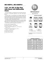
THERMAL RESISTANCE vs LENGTH<br />
100 150 200 250 300 350 400<br />
EXTRUSION LENGTH mm<br />
THERMAL RESISTANCE vs (Ts - Ta)<br />
75 70 65 60 55 50 45 40 35 30<br />
DELTA T = (HEATSINK TEMP. - AMBIENT TEMP.) °C<br />
2.0<br />
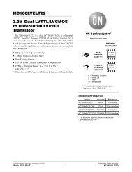
THERMAL RESISTANCE vs. AIR SPEED<br />
HOW TO INTERPRET THERMAL<br />
PERFORMANCE<br />
The extrusions are presented in order by shape<br />
and size. Dimensions are in mm with (inches)<br />
following in parenthesis. On the previous page<br />
there is an index sorted by extrusion part number.<br />
The part number, weight in kg/m, thermal resistance<br />
(R th,n with natural convection, thermal resistance<br />
R th,f with forced convection) at an air speed of<br />
2.0 m/s is shown for each extrusion. The thermal<br />
resistances have been calculated using 150 mm long<br />
vertical anodized heat sinks with a sink-to-ambient<br />
temperature difference of 75ºC and a uniform<br />
thermal load on the heat sink base.<br />
LENGTH CORRECTION FACTOR<br />
Because the air heats up while circulating through the<br />
extrusion, the convection coefficient is not constant<br />
throughout the extrusion length. Therefore, the<br />
thermal resistance changes nonlinearly as the length<br />
changes. To calculate the correct thermal resistance<br />
for extrusion lengths other than the standard 150 mm<br />
length, multiply the given thermal resistance data by<br />
the appropriate factor taken from the Thermal<br />
Resistance vs Length graph shown. The same<br />
correction factor must be used for thermal resistance<br />
in both natural convection and forced convection.<br />
TEMPERATURE CORRECTION FACTOR<br />
Both natural convection and radiation coefficients<br />
are related to the sink-to-ambient temperature<br />
difference. To evaluate the thermal performance of a<br />
heat sink for an application requiring a sink-to-ambient<br />
temperature rise other than 75ºC, use the correction<br />
factor from the Thermal Resistance vs (Ts - Ta) graph<br />
shown. This factor must be used only for thermal<br />
resistance in natural convection.<br />
RTH, f / RTH, f 2 m/s<br />
1.6<br />
1.2<br />
0.8<br />
0.4<br />
1.0 2.0 3.0 4.0 5.0<br />
AIR SPEED m/s<br />
AIR SPEED CORRECTION FACTOR<br />
The convection coefficient is also closely related to<br />
the air speed through the fins. Since evaluation of<br />
air speed through the fins is difficult to evaluate<br />
under normal circumstances, we show the thermal<br />
resistance of an extrusion in forced convection<br />
evaluated using a tunnel the same size as the<br />
extrusion. For a tunnel airflow other than 2 m/s,<br />
refer to the factor in the Thermal Resistance vs Air<br />
Speed graph shown. Use this factor to figure thermal<br />
resistance in forced convection.<br />
2<br />
Cheney Manor, Swindon,Wiltshire SN2 2QN • UK<br />
Tel: +44 (0) 1793 401400 • Fax: +44 (0) 1793 615396<br />
sales.uk@aavid.com<br />
via XXV Aprile, 32 - 40057 Cadriano (Bologna) • Italy<br />
Tel: +39 051 764011 • Fax: +39 051 764092<br />
sales.it@aavid.com