MISSION PLAN - PDS Small Bodies Node
MISSION PLAN - PDS Small Bodies Node
MISSION PLAN - PDS Small Bodies Node

You also want an ePaper? Increase the reach of your titles
YUMPU automatically turns print PDFs into web optimized ePapers that Google loves.
STARDUST<br />
<strong>MISSION</strong> <strong>PLAN</strong><br />
February 1, 1999<br />
J<br />
Jet Propulsion Laboratory<br />
California Institute of Technology
SD-75000-100-Revision A<br />
JPL D-300-1-Revision B
STARDUST<br />
<strong>MISSION</strong> <strong>PLAN</strong><br />
Edward A. Hirst<br />
Mission Design Engineer<br />
QuickTime and a<br />
Photo - JPEG decompressor<br />
are needed to see this picture.<br />
Chen-wan L. Yen<br />
Mission Design Manager<br />
February 1, 1999<br />
J<br />
Jet Propulsion Laboratory<br />
California Institute of Technology<br />
SD-75000-100-Revision A
JPL D-300-1-Revision B
Table of Contents<br />
Table of Contents<br />
List of Figures<br />
List of Tables<br />
List of Acronyms and Abbreviations<br />
Change Log<br />
i<br />
iii<br />
v<br />
vii<br />
ix<br />
1.0 Introduction 1<br />
1.1 Purpose 1<br />
1.2 Scope 1<br />
1.3 Relationship to Other Documents 1<br />
2.0 Mission Overview 2<br />
2.1 Mission Objectives<br />
2<br />
2.2 Project System Descriptions 2<br />
2.2.1 Launch Vehicle 2<br />
2.2.2 STARDUST Spacecraft 2<br />
2.2.2.1 General Configuration 2<br />
2.2.2.2 Aerogel Collector 5<br />
2.2.2.3 Imaging Camera 6<br />
2.2.2.4 Cometary and Interstellar Dust Analyzer (CIDA) 8<br />
and Dust Flux Monitor Instrument (DFMI)<br />
2.2.2.5 Sample Return Capsule (SRC) 9<br />
2.3 Mission Summary 10<br />
2.3.1 Description 10<br />
2.3.2 Launch Period Strategy 14<br />
2.3.2.1 Baseline Launch Period 14<br />
2.3.2.2 ∆V Budget 20<br />
2.3.2.3 Alternate Launch Periods 20<br />
2.3.3 Space Environment 21<br />
2.3.3.1 Ionizing Radiation Fluence and Dose 21<br />
2.3.3.2 Single Event Upsets 24<br />
2.3.3.3 Micrometeoriod 29<br />
2.4 Science Investigation Descriptions 29<br />
2.4.1 Science Investigation Requirements 29<br />
2.4.2 Comet Wild-2 30<br />
2.4.2.1 Orbit 30<br />
2.4.2.2 Nucleus and Coma 30<br />
2.4.2.3 Dust Environment 31<br />
2.4.3 Interstellar Dust Particle (ISP) Sizes, Impact Velocity and 33<br />
Direction<br />
2.4.4 Interstellar Dust Science Planning Constraints 34<br />
3.0 Launch Phase (L+0 to L+30 days) 35<br />
3.1 Overview 35<br />
3.2 Initial Acquisition Subphase 36<br />
i
3.3 Activation and Checkout Subphase 38<br />
3.4 Mission Operations 39<br />
4.0 Cruise Phases 40<br />
4.1 Overview 40<br />
4.2 Interstellar Dust Science 40<br />
4.2.1 Interstellar Particle Collection Subphases 41<br />
4.2.2 Cruise Phase CIDA Experiment 44<br />
4.2.3 Expansion Opportunities for Interstellar Particle 47<br />
Experiments<br />
4.2.4 Mission Operation Considerations 49<br />
4.3 Mission Operations 49<br />
5.0 Earth Gravity Assist Phase (EGA-60 to EGA+30 days) 52<br />
5.1 Overview 52<br />
5.2 Mission Operations 53<br />
6.0 Wild-2 Encounter Phase (E-100 to E+50 days) 54<br />
6.1 Overview 54<br />
6.2 Science Operations<br />
58<br />
6.2.1 Aerogel Collection of Cometary Dust 58<br />
6.2.2 Comet Coma and Nucleus Imaging 58<br />
6.2.2.1 Coma Images 58<br />
6.2.2.2 Nucleus Images 60<br />
6.2.2.3 Imaging Calibrations 61<br />
6.2.3 CIDA and DFMI Encounter Experiments 62<br />
6.2.4 Delivery Accuracy and Science Implications 62<br />
6.2.5 Nucleus Tracking 63<br />
6.3 Mission Operations 64<br />
7.0 Earth Return Phase (ER-90 to ER+1 day) 67<br />
7.1 Overview 67<br />
7.2 Earth Return Operations 68<br />
7.2.1 Approach Subphase 68<br />
7.2.1.1 Earth Entry Control 68<br />
7.2.1.2 Navigation Requirements 69<br />
7.2.1.3 Spacecraft / SRC Separation 69<br />
7.2.2 Entry, Descent and Recovery Subphases 70<br />
7.3 Mission Operations 72<br />
8.0 Planetary Protection 73<br />
9.0 Appendix A: Geometry Data Sets 74<br />
9.1 Mission Data Set 75<br />
9.2 Launch Phase Data Set 77<br />
9.3 Earth Gravity Assist Data Set 80<br />
9.4 Wild-2 Encounter Data Set 83<br />
9.5 Earth Return Data Set 90<br />
10.0 Appendix B: Attitude Control Unbalanced Thruster Modeling 93<br />
10.1 Limit Cycle Model 93<br />
ii
10.1.1 Spacecraft Attitude History 93<br />
10.1.2 Attitude Control Force Modeling 94<br />
10.1.3 Model Parameters and Characteristics 96<br />
10.2 Slew ∆V Model 98<br />
10.2.1 Slew Types and ∆V Equations 99<br />
10.2.2 Spacecraft Slew History 100<br />
10.2.3 Model Parameters and Characteristics 102<br />
11.0 Appendix C: Event Listing 109<br />
12.0 Appendix D: ISP Collection and CIDA Experiment Tables 115<br />
13.0 Appendix E: PRD Traceability Matrix 134<br />
iii
List of Figures<br />
Figure 2.2-1.a STARDUST Configuration in Launch Vehicle 3<br />
Figure 2.2-1.b Boeing Delta II 7426 3<br />
Figure 2.2-2 STARDUST Configuration during Encounter 4<br />
Figure 2.2-2.a Spacecraft Antennas Fields-of-View 4<br />
Figure 2.2-3.a Aerogel Collector - deployed 6<br />
Figure 2.2-3.b Aerogel Collector - stowed 6<br />
Figure 2.2-3.c Aerogel Grid Deployment Geometry 7<br />
Figure 2.2-4 Imaging Camera 7<br />
Figure 2.2-5.a CIDA and DFMI 8<br />
Figure 2.2-5.b CIDA FOV and Sun Avoidance 9<br />
Figure 2.2-6 Sample Return Capsule 10<br />
Figure 2.3-1 STARDUST (E-E-W2-E) Heliocentric Trajectory 11<br />
Figure 2.3-2 STARDUST Mission Overview (1999-2006) 13<br />
Figure 2.3-3 Radiation Dose vs Shield Depth (Spherical Aluminum Shell) 25<br />
Figure 2.3-4.a. Proton Fluence vs Energy as a Function of Time from Launch 25<br />
Figure 2.3-4.b.<br />
Electron Fluence vs Energy as a Function of Time from Launch<br />
26<br />
Figure 2.3-5.a. Equivalent 1-MeV Electron Fluence vs Thickness and Time 26<br />
from Launch for Effects on Open Circuit Voltage or Max Power<br />
Figure 2.3-5.b. Equivalent 1-MeV Electron Fluence vs Thickness and Time 27<br />
from Launch for Effects on Short Circuit Current<br />
Figure 2.3-6.a. Heavy-ion Flux from a 99% Solar Flare at 1 AU and for 28<br />
Adams’ 90% Worst Case GCR<br />
Figure 2.3-6.b. Heavy-ion Flux from a 95% Solar Flare at 1 AU and for 28<br />
Adams’ 90% Worst Case GCR<br />
Figure 3.1-1 Launch Phase Spacecraft Trajectory 35<br />
Figure 3.2-1.a Launch Vehicle Boost Profile 37<br />
Figure 3.2-1.b Spacecraft Orbit Injection Profile 38<br />
Figure 4.2-1 Profile of ISP Collection Experiment - Loop 1 42<br />
Figure 4.2-2 ISP Impact Velocity History (β=1 particle) 43<br />
Figure 4.2-3.a Spacecraft +z-axis Off-sun and Off-Earth Angle History 43<br />
Figure 4.2-3.b Spacecraft +y-axis Yaw Angle History 43<br />
Figure 4.2-4.a Collector Deployment Angle and Grid Exposure History 44<br />
Figure 4.2-4.b Beta Meteoriod Impact Angle 44<br />
Figure 4.2-5 Profile of CIDA Experiment - Loop 1 45<br />
Figure 4.2-6.a Spacecraft +z-axis Off-sun and Off-Earth Angle History 46<br />
Figure 4.2-6.b Spacecraft +y-axis Yaw Angle History 46<br />
Figure 4.2-7 ISP off +x-axis Angle and Field-of-View Exposure History 47<br />
Figure 4.2-8 ISP 1 Variability Across the Launch Period 48<br />
Figure 5.1-1 Earth Gravity Assist Phase Spacecraft Trajectory 53<br />
Figure 6.1-1 Encounter Phase Spacecraft Trajectory 56<br />
Figure 6.1-2 Encounter Elevation Angle Profile 56<br />
Figure 6.1-3 Wild-2 Encounter Phase Overview (Far and Post Sub-phases) 57<br />
iv
Figure 6.2-1.a Wild-2 Encounter Comet Profile - Far Encounter 58<br />
Figure 6.2-1.b Wild-2 Encounter Comet Profile - Near Encounter 59<br />
Figure 6.2-1.c Wild-2 Encounter Comet Profile - Close Encounter 59<br />
Figure 6.2-2 Image Memory Storage 61<br />
Figure 6.2-3 Delivery Error Growth: Nucleus Image Offset vs. Time 63<br />
Figure 6.2-4 Roll Angle vs. Delivery Error and Flyby Distance 64<br />
Figure 7.1-1 Earth Return Phase Spacecraft Trajectory 68<br />
Figure 7.2-1 Approach B-Plane Front View 69<br />
Figure 7.2-2 SRC Entry Profile 70<br />
Figure 7.2-3 Posigrade Landing Footprint 71<br />
9.0 Appendix A: Geometry Data Set Figures 74<br />
9.1 Mission Data Set 75<br />
9.2 Launch Phase Data Set 77<br />
9.3 Earth Gravity Assist Data Set 80<br />
9.4 Wild-2 Encounter Data Set 83<br />
9.5 Earth Return Data Set 90<br />
Figure 10.1-1 Total Thruster Pulse History 97<br />
Figure 10.1-2 Mass Flow Rate History 97<br />
Figure 10.1-3 Acceleration Magnitude History 98<br />
Figure 10.1-4 Acceleration Direction History 98<br />
Figure 10.2-1 Spacecraft Rotation Angles 100<br />
Figure 10.2-2 Slew ∆V Magnitude Profile 103<br />
Figure 10.2-3 Slew ∆V Direction Comparison - Declination 103<br />
Figure 10.2-4 Slew ∆V Direction Comparison - Right Ascension 103<br />
v
List of Tables<br />
Table 2.2-1 STARDUST Mass Element List (Rev. Z) 5<br />
Table 2.3-1 STARDUST Mission Phases 12<br />
Table 2.3-2 Baseline Mission Parameters vs. Launch Date 15<br />
Table 2.3-2.a ∆V Budget Summary 20<br />
Table 2.3-2.b Maneuver History 20<br />
Table 2.3-3 STARDUST Alternate-1 Mission Parameters: 2 + yr<br />
Table 2.3-4<br />
∆V-EGA Trajectory 22<br />
STARDUST Alternate-2 Mission Parameters : 2 - yr<br />
∆V-EGA Trajectory 23<br />
Table 2.3-5 Proton and Electron Integral Fluence Spectra for 24<br />
STARDUST Mission<br />
Table 2.3-6 Probability of Large Solar Flares 27<br />
Table 2.3-7 STARDUST Mission Micrometeoriod Environment 29<br />
Table 2.4-1 Current Best Estimate of Wild-2 Orbital Elements 30<br />
Table 2.4-2 Projected Position Uncertainty of Comet Wild-2 at Encounter 30<br />
Table 2.4-3 P/Wild-2 Nucleus Radius Observation Reduction 31<br />
Table 2.4-4 Wild-2 Dust Model (assuming 150 km flyby @ 6.1 km/s) 32<br />
Table 2.4-5 Particle Size Estimate 33<br />
Table 3.1-1 Launch Phase Subphase Definition 35<br />
Table 3.2-1 Injection Activities 36<br />
Table 3.3-1 Subsystem Checkout Plan 38<br />
Table 3.3-2 Launch Phase Imaging Plan 39<br />
Table 3.4-1 Launch Phase Mission Operations 39<br />
Table 4.1-1 Cruise Phase Subphase Definition 40<br />
Table 4.2-1.a Interstellar Particle Collection Subphases 41<br />
Table 4.2-1.b Reference Plane Definitions 42<br />
Table 4.2-2 Interstellar Particle Related CIDA Experiment Periods 45<br />
Table 4.3-1.a Cruise Phase Mission Operations 50<br />
Table 4.3-1.b Cruise Phase Mission Operations - DSN Profile 50<br />
Table 4.3-1.c Cruise Phase Mission Operations - Spacecraft Attitude 51<br />
Table 4.3-2 Cruise Phase Imaging Plan 51<br />
Table 5.1-1 Earth Gravity Assist Phase Subphase Definition 52<br />
Table 5.2-1 Earth Gravity Assist Phase Mission Operations 53<br />
Table 6.1-1 Wild-2 Encounter Phase Subphase Definition 55<br />
Table 6.2-1 Allowable Near Encounter Image Size 60<br />
Table 6.2-2 Encounter Imaging Calibrations 61<br />
Table 6.2-3 Encounter Delivery Accuracy (1-sigma) 62<br />
Table 6.3-1 Wild-2 Encounter Phase Mission Operations 65<br />
Table 6.3-2 OPNAV Plan 66<br />
Table 7.1-1 Earth Return Phase Subphase Definition 67<br />
Table 7.2-1 SRC Entry Requirements 68<br />
Table 7.3-1 Earth Return Phase Mission Operations 72<br />
Table 10.1-1 Spacecraft Attitude Options - Limit Cycle Model 94<br />
Table 10.1-2 Spacecraft Deadband Options - Limit Cycle Model 94<br />
vi
Table 10.1-3 Spacecraft Attitude Profile - Limit Cycle Model 96<br />
Table 10.1-4 ACS Force Model Parameters 97<br />
Table 10.2-1 Slew Types and ∆V Equations 99<br />
Table 10.2-2 Slew Groups 100<br />
Table 10.2-3 Spacecraft Attitude Options - Slew ∆V Model 101<br />
Table 10.2-4 Spacecraft Deadband Options - Slew ∆V Model 102<br />
Table 10.2-5 Spacecraft Attitude Profile - Slew ∆V Model 104<br />
Table 10.2-6 Communications Schedule 105<br />
Table 10.2-7 OPNAV Schedule 108<br />
Table 11-1 Event Listing 109<br />
Table 11-2 Time Ordered Event Listing 113<br />
Table 12-1 ISP#1 Collection Period Characteristics 116<br />
Table 12-2 ISP#2 Collection Period Characteristics 117<br />
Table 12-3 ISP#1 Spacecraft Attitude [EME’2000] 119<br />
Table 12-4 ISP#2 Spacecraft Attitude [EME’2000] 120<br />
Table 12-5 CIDA#1 Experiment Period Characteristics 122<br />
Table 12-6 CIDA#2 Experiment Period Characteristics 124<br />
Table 12-7 CIDA#3 Experiment Period Characteristics 126<br />
Table 12-8 CIDA#1 Spacecraft Attitude [EME’2000] 127<br />
Table 12-9 CIDA#2 Spacecraft Attitude [EME’2000] 129<br />
Table 12-10 CIDA#3 Spacecraft Attitude [EME’2000] 131<br />
Table 12-11 CIDA#3 Solar Conjunction Characteristics 132<br />
Table 12-12 CIDA#3 Solar Conjunction Spacecraft Attitude [EME’2000] 133<br />
vii
List of Acronyms and Abbreviations<br />
β<br />
Beta<br />
∆V Delta-Velocity<br />
λ<br />
Wavelength<br />
µm Micrometer<br />
# Number<br />
A-h<br />
Acq<br />
ACS<br />
AD<br />
Alt<br />
ARIA<br />
AU<br />
bps<br />
Ampere-hour<br />
Acquisition<br />
Attitude Control<br />
System<br />
ER Arrival Date<br />
Altitude<br />
Advanced Range<br />
Instrumentation Aircraft<br />
Astronomical Unit<br />
Bits Per Second<br />
Instrument<br />
DSM Deep Space Maneuver<br />
DSN Deep Space Network<br />
DST Deep Space Transponder<br />
E, Enc Encounter, Wild-2<br />
Ear Earth<br />
EE Earth-Earth<br />
EGA Earth Gravity Assist<br />
EGAD Earth Gravity Assist Date<br />
eng Engineering<br />
EPS Electrical Power System<br />
ER Earth Return<br />
ET Ephemeris Time<br />
EW Earth-Wild-2<br />
FOV Field Of View<br />
fps Feet Per Second<br />
ft<br />
Feet<br />
C3<br />
cc<br />
CCD<br />
C&DH<br />
CIDA<br />
cm<br />
CMD<br />
conj<br />
cos<br />
COSPAR<br />
d<br />
D<br />
Dap<br />
dB<br />
Dec<br />
deg<br />
DFMI<br />
Injection Energy Per Unit<br />
Mass<br />
Cubic Centimeters<br />
Charge Coupled Device<br />
Command and Data<br />
Handling<br />
Cometary and Interstellar<br />
Dust Analyzer<br />
Centimeter<br />
Command<br />
Conjunction<br />
Cosine<br />
Committee On Space<br />
Research<br />
Day<br />
Dimension<br />
Declination, approach<br />
Decibel<br />
Declination<br />
Degrees<br />
Dust Flux Monitor<br />
g<br />
g<br />
GCR<br />
Ghz<br />
h<br />
h<br />
HEF<br />
HGA<br />
img<br />
IMU<br />
Unit<br />
ISC<br />
ISP<br />
JPL<br />
JSC<br />
Grams<br />
Unit Of Acceleration<br />
Equal To Earth’s Gravity<br />
Galactic Cosmic Ray<br />
Giga-hertz<br />
Altitude<br />
Hour<br />
High-Efficiency<br />
High Gain Antenna<br />
Image<br />
Inertial Measurement<br />
Current, Short Circuit<br />
Interstellar Dust Particle<br />
Jet Propulsion Laboratory<br />
Johnson Space Center<br />
viii
kg<br />
km<br />
L<br />
L/O<br />
Kilogram<br />
Kilometer<br />
Launch<br />
Liftoff<br />
lb<br />
lb-f<br />
LD<br />
LGA<br />
LMA<br />
Pound<br />
Foot-Pound<br />
Launch Date<br />
Low Gain Antenna<br />
Lockheed Martin<br />
Astronautics<br />
List of Acronyms and Abbreviations (cont)<br />
m, min Minute<br />
m, M Meter<br />
mag Magnitude<br />
max Maximum<br />
MECO Main Engine Cutoff<br />
MEL Mass Element List<br />
mem Memory<br />
MeV Million Electron Volts<br />
MGA Medium Gain Antenna<br />
mm Millimeter<br />
MSL Mean Sea Level<br />
ms Millisecond<br />
N<br />
North<br />
NASA National Aeronautics and<br />
Space Administration<br />
Nav Navigation<br />
NCS Nutation Control System<br />
nmi Nautical Miles<br />
OD Orbit Determination<br />
OPNAV Optical Navigation<br />
opp Opposition<br />
Rap<br />
Rcvr<br />
RDM<br />
Re<br />
Req’d<br />
RFS<br />
RPM<br />
Rs<br />
Right Ascension,<br />
approach<br />
Receiver<br />
Radiation Design Margin<br />
Range, Earth<br />
Required<br />
Radio Frequency<br />
System<br />
Revolutions Per Minute<br />
Range, Solar<br />
s, sec Second<br />
seg Segment<br />
S<br />
South<br />
S<br />
Unit Vector Orthogonal<br />
To R, In Direction Of<br />
Target Body Velocity<br />
S/A Solar Array<br />
S/C Spacecraft<br />
SECO Stage II Engine Cutoff<br />
SRC Sample Return Capsule<br />
SRM Solid Rocket Motor<br />
SSPA Solid-State Power<br />
Amplifier<br />
Pmax<br />
PMS<br />
R<br />
Ra<br />
Potential, refers to Open<br />
Circuit Voltage<br />
Power Management<br />
Subsystem<br />
Unit Vector Along Sun-<br />
Target Body Line<br />
Right Ascension<br />
t<br />
T<br />
TBD<br />
TBR<br />
TCM<br />
TP<br />
Time<br />
Out Of Plane Unit Vector<br />
To Be Determined<br />
To Be Resolved<br />
Trajectory Correction<br />
Maneuver<br />
Time Of Perihelion<br />
Passage<br />
ix
UHF<br />
UTTR<br />
v<br />
VEGA<br />
Vhp,b<br />
Ultra High Frequency<br />
Utah Test and Training<br />
Range<br />
Velocity<br />
Soviet Mission to Venus<br />
& Comet Halley (1984-6)<br />
Velocity, hyperbolic,<br />
approach<br />
VOC Voltage, Open Circuit<br />
W<br />
Watts<br />
w, wk Week<br />
W2 Wild-2, comet<br />
WE Wild-2-Earth<br />
WRT With Respect To<br />
yr<br />
Year<br />
x
Change Log<br />
Change Letter Date Affected Sections<br />
Original Issue<br />
Revision A<br />
Revision B<br />
10/7/1995<br />
1/28/1997<br />
2/1/1999<br />
All<br />
All<br />
1.1, 1.2, 1.3, 2.2.1, 2.2.2.x, 2.3.1, 2.3.2.1, 2.3.2.2,<br />
2.4.1, 2.4.2.1, 2.4.2.3, 2.4.3, 2.4.4*, 3.2, 3.3, 3.4,<br />
4.1, 4.2, 4.2.x*, 4.3, 5.1, 5.2, 6.1, 6.2.2.1, 6.2.2.3*,<br />
6.2.4, 6.3, 7.1, 7.2.1.1, 7.2.2, 7.3*, 9.2, 9.3, 10.x*,<br />
11.x*, 12.x*, 13.0*<br />
(see change paper XF0236)<br />
* includes new sections<br />
xi
page i nt ent i onal l y l ef t bl ank ><br />
xii
1.0 Introduction<br />
1.1 Purpose<br />
The purposes of this document are to:<br />
1. Provide a detailed description of the current STARDUST mission plan which<br />
constitutes the basis for flight system design and mission operations,<br />
2. Illustrate that the STARDUST mission has been designed to fulfill the primary<br />
science objectives and maximize the secondary science objectives, and<br />
3. Show that the planned mission adheres to the “design-to-cost and capability”<br />
paradigm and represents a balanced plan where the science goals and the current<br />
flight system capabilities are in good agreement.<br />
The plan described herein is considered as the basis for the development of flight systems<br />
and the mission operations plan to be implemented in the project phases C/D, and E.<br />
1.2 Scope<br />
This document presents the baseline, end-to-end, mission scenario and is a source for<br />
establishing spacecraft performance and mission operations requirements. Although the<br />
mission architecture has considered mission parameters and profiles corresponding to a<br />
proposed 20-day launch period, the specific events and mission timelines presented<br />
herein are corresponding primarily to the first launch date, 06 February 1999. Some<br />
details will become obsolete if the launch should occur on another day. An update to<br />
selected portions of this mission plan is envisioned within a month of launch. This<br />
update will reflect changes to the mission plan as a function of the actual launch date.<br />
Future changes, needed as project system definitions mature, will be introduced under a<br />
formal mission plan change control procedure.<br />
1.3 Relationship to Other Documents<br />
This version of the Mission Plan is consistent and responsive to the requirements,<br />
objectives, and detailed plans described in the following documents:<br />
STARDUST Project Management<br />
Project Requirements<br />
Science Requirements<br />
Flight Systems Requirements<br />
STARDUST Design Reference Mission<br />
STARDUST Sample Return Capsule Recovery Operations Plan<br />
Navigation Plan<br />
SD-10000-110<br />
SD-30000-200<br />
SD-40000-200<br />
SD-62000-200<br />
SD-62400-300<br />
SD-73110-100<br />
SD-76000-100<br />
1
Mission Operation & Ground Data Systems Plans<br />
Wild-2 Flyby Targeting Plan<br />
STARDUST Mission Environmental Assessment<br />
SD-72000-100<br />
SD-77000-300<br />
JPL-D-14159<br />
2
2.0 Mission Overview<br />
2.1 Mission Objectives<br />
The primary science goal of the STARDUST mission is to collect comet Wild-2 coma<br />
samples, plus bonus interstellar dust samples, in an aerogel medium, and return them to<br />
Earth. Additional science return is anticipated in the form of images of the comet coma<br />
and nucleus, Comet and Interstellar Dust Analyzer (CIDA) based dust particle analysis<br />
and dust flux monitoring.<br />
These science goals lead to the following objectives in the design of the STARDUST<br />
mission:<br />
• Provide a flyby of a comet of interest (Wild-2) at a sufficiently low velocity (less than<br />
6.5 km/s) such that non-destructive capture of comet dust is possible using an aerogel<br />
collector.<br />
• Facilitate the intercept of significant numbers of interstellar dust particles using the<br />
same collection medium, also at as low a velocity as possible.<br />
• Return as many high resolution images of the comet coma and nucleus as possible,<br />
subject to the cost constraints of the mission.<br />
More specific definition of the science objectives can be found in Section 2.4 Science<br />
Investigation Descriptions.<br />
2.2 Project System Descriptions<br />
2.2.1 Launch Vehicle<br />
The launch vehicle for STARDUST is a Boeing Delta II 7426. Given its four solid<br />
rocket motors and a Star 37FM upper stage without a Nutation Control System (NCS),<br />
thermal barrier or despin add-ons, it is capable of delivering 396 kgs at a C3 of 26 km 2 /s 2 .<br />
Figure 2.2-1.a shows the STARDUST spacecraft configuration while inside the launch<br />
vehicle and Figure 2.2-1.b shows the launch vehicle itself.<br />
2.2.2 STARDUST Spacecraft<br />
2.2.2.1 General Configuration<br />
3
STARDUST is a 3-axis stabilized spacecraft designed to perform its prime mission<br />
(Wild-2 encounter) at 1.9 AU from the sun and 2.6 AU from the Earth. During the cruise<br />
periods to and from this encounter, it must be able to function adequately at a maximum<br />
distance of 2.7 AU from the sun and 3.6 AU from the Earth.<br />
QuickTime and a<br />
Photo - JPEG decompressor<br />
are needed to see this picture<br />
Figure 2.2-1.a STARDUST Configuration in Launch Vehicle<br />
+y<br />
4
Fairing<br />
STARDUST<br />
Second Stage<br />
Star37FM upper stage<br />
First Stage<br />
Solid Rocket Motors<br />
Figure 2.2-1.b Boeing Delta II 7426<br />
The spacecraft, shown in Figure 2.2-2 in its encounter configuration, is equipped with a<br />
power subsystem, fixed solar panels and one rechargeable battery, capable of delivering a<br />
minimum of 170 watts (W) during standard cruise operations at aphelion and a minimum<br />
of 300 W at comet encounter. The solar panels have a maximum off-sun pointing<br />
constraint of 60° to avoid problems caused by refraction of light.<br />
5
Sample<br />
Return<br />
Capsule<br />
(open)<br />
Solar Panels<br />
Aerogel Collector<br />
(comet side)<br />
HGA<br />
MGA<br />
CIDA not shown.<br />
Mounted on +y deck.<br />
(see Fig. 2.2-5.a)<br />
LGAs: 1 on +z deck,<br />
2 on -z deck.<br />
+z, yaw<br />
Thruster<br />
cluster<br />
(1 of 4)<br />
+y, pitch<br />
Camera / Mirror<br />
+x, roll<br />
VIEW: +x, -y, +z<br />
Periscope<br />
DFMI<br />
Whipple Shields<br />
Figure 2.2-2 STARDUST Configuration during Encounter<br />
Communications are achieved via either a high-gain, medium-gain or one of three low<br />
gain antennas. During the mission, Deep Space Network (DSN) support will be provided<br />
with primarily 34-m antennas with 70-m support being used during the close comet<br />
encounter. These antennas provide the capability for a minimum of 4000 bits per second<br />
(bps), 7900 bps expected, at encounter via the high-gain antenna and a 70-m DSN station<br />
and 40 bps at maximum Earth range via the medium gain antenna and a 34-m DSN<br />
station. The low-gain antennas, in conjunction with a 34-m DSN antenna, are ideal for<br />
near-Earth phases (Launch, Earth flyby and Earth return) when Sun-Earth-spacecraft<br />
angles are near 90°, especially since they can support communications within 0.05 AU<br />
(+3 dB margin) of the Earth at a minimum data rate of 40 bps. Antenna locations and<br />
fields-of-view are as described in Figure 2.2-2.a.<br />
MGA ± 6.6°<br />
7° off-set<br />
HGA ± 2.1°<br />
LGA2 ± 75°<br />
+z<br />
+x<br />
LGA1 & 3 ± 40°<br />
45°off-set, one each<br />
on ± y axis deck<br />
Figure 2.2-2.a Spacecraft Antennas Fields-of-View<br />
Attitude control and propulsive maneuvers are performed using a redundant helium-fed<br />
mono-propellant (hydrazine) propulsion subsystem. The subsystem is comprised of one<br />
titanium propellant tank and a total of 16 thrusters (two strings of 8), all mounted on the<br />
lower deck of the spacecraft (opposite the high-gain antenna and solar panels - pointing<br />
toward the -z-axis of the spacecraft). Eight of these are 0.2 lb-f thrusters and are used<br />
primarily for attitude control. The other eight are 1.0 lb-f thrusters and are used for<br />
6
propulsive maneuvers. To avoid potential contamination of the aerogel collector,<br />
placement of thrusters on the upper deck (+z) is avoided. This configuration, however,<br />
generates uncoupled thrusts during attitude control burns and adds complexity to<br />
trajectory simulations.<br />
The normal spacecraft attitude during the mission points the +z-axis of the spacecraft to<br />
the sun. Deviations from the normal attitude are performed during communication<br />
periods and delta-velocity (∆V) burns. Off-sun pointing is also permitted during nonprimary<br />
science experiments, CIDA and Interstellar Dust Particle (ISP) collection, as<br />
long as the power generated by the solar arrays is adequate at the desired off-sun angle.<br />
During the comet encounter period, the +x-axis is pointed to the dust stream.<br />
Also visible in Figure 2.2-2 are the main bus and solar panel whipple shields. These<br />
shields are placed on the spacecraft to protect it from high velocity dust impacts during<br />
comet encounter. The barriers are designed to stop a 1 cm size particle traveling at 6<br />
km/s (which is essentially equal to the comet encounter relative velocity).<br />
Science objectives are met using three science subsystems: Aerogel Dust Collector and<br />
Sample Return Capsule (SRC), Cometary and Interstellar Dust Analyzer (CIDA) and the<br />
Dust Flux Monitor Instrument (DFMI). The imaging camera is also used for science<br />
purposes but its main function is to perform optical navigation prior to encounter with<br />
comet Wild-2.<br />
The current best estimate of the mass breakdown of the flight system is summarized in<br />
Table 2.2-1. It should be noted that this table is provided for illustrative purposes and is<br />
subject to change as per updates to the Mass Element List (MEL). Table 2.2-1 is based<br />
on Revision Z.<br />
Table 2.2-1 STARDUST Mass Element List (Rev. Z)<br />
Component Mass (kg) Component Mass (kg)<br />
S/C Power 33.378 Navigation Camera 12.686<br />
S/C Harness 20.971 DFMI 1.530<br />
S/C Telecom 19.222 CIDA 10.966<br />
S/C ACS 9.951 SRC Avionics 1.992<br />
S/C C&DH 10.394 SRC Harness 0.869<br />
S/C Thermal 10.060 SRC Thermal 13.683<br />
S/C Structures 104.412 SRC Structures 9.271<br />
S/C Mechanisms 6.131 SRC Mechanisms 17.184<br />
S/C Propulsion 19.538 SRC Parachute 4.194<br />
Pressurant (He) 0.202 Total Dry 305.397<br />
Propellant 85.000 Total Wet 390.599<br />
2.2.2.2 Aerogel Collector<br />
7
Capture of cometary and interstellar dust particles is performed using the Aerogel Dust<br />
Collector. The aerogel collector allows collection from both sides. Figure 2.2-3.a shows<br />
the aerogel collector fully deployed from the SRC canister. In the figure, the visible side<br />
of the collector is used for cometary dust collection while the hidden side is used for<br />
interstellar dust collection. The total collection area per side is required to be greater<br />
than 1000 cm 2 . Stowing of the collector is achieved by first folding the collector grid<br />
onto the boom via the wrist joint and then folding the boom/collector into the SRC<br />
canister via the shoulder joint as shown in Figure 2.2-3.b<br />
Interstellar<br />
collection<br />
Aerogel<br />
collector<br />
Cometary<br />
collection<br />
wrist<br />
joint<br />
shoulder<br />
joint<br />
a. deployed b. stowed<br />
Figure 2.2-3 Aerogel Collector<br />
This deployment mechanism is the key in maximizing the amount of time available for<br />
the capture of interstellar dust particles. The mechanism allows the collector to be<br />
steered via the wrist joint about the spacecraft y-axis toward the -z-axis. The collector<br />
field-of-view remains unobstructed by the SRC backshield for 51° of this motion, half the<br />
grid is in shadow at 63°, and all of the grid is in shadow at 75°. This deployment<br />
geometry is illustrated in Figure 2.2-3.c. Note that for the shadow definition, the ISP<br />
stream is assumed to be incoming perpendicular to the aerogel grid. It is worth noting<br />
that the collector field-of-view would remain completely unobstructed for 65° of the<br />
motion should the shoulder joint be used during interstellar dust particle collection.<br />
However, usage of the shoulder joint with the collector fully deployed is considered to be<br />
an unnecessary risk. A description of the ISP collection strategy is provided in Section<br />
4.2.1 Interstellar Particle Collection Subphases.<br />
2.2.2.3 Imaging Camera<br />
8
The STARDUST camera is necessary to perform the optical navigation (OPNAV) that is<br />
required to achieve a flyby accurate enough to assure adequate comet dust collection.<br />
This camera also provides the capability to obtain high-resolution images of the comet<br />
coma and comet nucleus during the close encounter. The imaging camera is<br />
Milstar/CASSINI-inherited with the following characteristics:<br />
CCD: 1024 x 1024 pixels, 12 bits/pixel Focal ratio: f/3.5<br />
Pixel Size: 12 µmeters<br />
Shutter speeds: 5ms - 10s, 5ms steps<br />
FOV: 3.5°<br />
Readout time: ~3 sec<br />
Pixel FOV: 60 µradians Number of Filters: 8<br />
Focal length: 200 mm<br />
Spectral range: 380 - 1100 nm<br />
start<br />
shadow<br />
half<br />
shadow<br />
fully<br />
shadowed<br />
no shadow<br />
grid fully<br />
deployed<br />
75.1°<br />
62.6°<br />
50.9°<br />
75.1° - 75°<br />
62.6° - 63°<br />
50.9° - 51°<br />
+z<br />
+x<br />
SRC<br />
backshell<br />
Figure 2.2-3.c Aerogel Grid Deployment Geometry<br />
The camera, shown in Figure 2.2-4, is equipped with a one-axis movable mirror which<br />
allows for image smear compensation during cometary encounter. In addition, a<br />
periscope is introduced into the optical path while imaging through the dust shields to<br />
protect the camera optics in the cometary dust environment.<br />
9
QuickTime and a<br />
Photo - JPEG decompressor<br />
are needed to see this picture.<br />
(-y panel removed)<br />
Figure 2.2-4 Imaging Camera<br />
2.2.2.4 Cometary and Interstellar Dust Analyzer (CIDA)<br />
and Dust Flux Monitor Instrument (DFMI)<br />
The Cometary and Interstellar Dust Analyzer (CIDA), a time-of-flight mass<br />
spectrometer, and the Dust Flux Monitor Instrument (DFMI) are shown in Figure 2.2-5.a.<br />
These instruments are mounted on the spacecraft such that their line of sight is in the<br />
same direction as the comet side of the aerogel collector (i.e. toward the spacecraft +xaxis).<br />
QuickTime and a<br />
Photo - JPEG decompressor<br />
are needed to see this picture.<br />
Figure 2.2-5.a. CIDA and DFMI<br />
Without consideration of spacecraft obstructions, the field-of-view of CIDA’s target<br />
surface is a 180° hemisphere. However, once mounted on the spacecraft, the CIDA field-<br />
10
of-view is smaller, as described in Figure 2.2-5.b. Constrained by the dust shield and<br />
spacecraft bus in the +z axis direction, the field-of-view spans 52° in the x-z plane.<br />
Along the y-axis (in and out of the page), the field-of-view is limited only by the fact that<br />
the particles must impact the target surface, which is recessed, to be analyzed.<br />
The science investigations that use these instruments will take opportunistic observations<br />
of the comet and interstellar dust. Their observing periods are mainly constrained by<br />
available spacecraft power. CIDA operation, however, is also constrained by the need to<br />
maintain sunlight off the target surface while CIDA is powered on.<br />
The CIDA sun avoidance constraint (which includes scattered and reflected light) is<br />
applied to the mission design as shown in Figure 2.2-5.b. In defining the constrained<br />
regions, it is assumed that sunlight cannot penetrate from the +z-axis side of the<br />
spacecraft bus to the -z-axis side, sunlight cannot penetrate through the dust shield and<br />
there are no gaps between the two. It is also assumed that the CIDA target is recessed<br />
into the target block such that the small region (1.6° in size) in the -x/+z quadrant of the<br />
figure is too small for the sun to hit the target. The sun avoidance region thus becomes<br />
the same as the CIDA field-of-view and, in light of the maximum solar array off-point<br />
angle of 60°, it is concluded that sun avoidance is of no major concern during standard<br />
operations. In fact, it should only be of concern during extreme off-pointing as may be<br />
expected during propulsive maneuvers.<br />
It must be noted that the CIDA field-of-view, as per the current Project Requirements<br />
Document, is only required to be 20° in size. The field-of-view as described in this<br />
+z<br />
1.6°<br />
SUN AVOIDANCE<br />
2°<br />
Target<br />
Angle too<br />
small for<br />
Sun to hit<br />
target<br />
+x<br />
CIDA<br />
FOV<br />
50°<br />
Only<br />
Sun<br />
possible<br />
~ 6 in<br />
Figure 2.2-5.b. CIDA FOV and Sun Avoidance<br />
document is what is available given the current spacecraft configuration as of the<br />
publishing of this document and should not be interpreted as a requirement on spacecraft<br />
design.<br />
2.2.2.5 Sample Return Capsule (SRC)<br />
11
The Sample Return Capsule is mounted along the -x-axis of the spacecraft. It is a key<br />
component that allows successful return of the cometary samples to Earth. Shown in<br />
Figure 2.2-6, there are four main components to the SRC: the avionics, the aeroshell<br />
(backshell and heat shield), the sample collector, and the parachute system.<br />
The avionics design includes a UHF locator beacon that will be used as an SRC location<br />
aid for the ground recovery team. The beacon is activated upon main chute deployment.<br />
It is powered by a set of primary cell lithium sulfur dioxide batteries. Lithium sulfur<br />
dioxide was selected because of its long shelf life, tolerance to wide temperature<br />
variations, and handling safety. These batteries have enough capacity to operate the<br />
beacon for 40 hours. Additional SRC tracking is provided by skin tracking from two C-<br />
band radar sites at the Utah Test and Training Range (UTTR) landing site. A mylar<br />
target mounted on the main chute provides an equivalent one square meter of radar cross<br />
section.<br />
The aeroshell is used to remove over 99 percent of the initial kinetic energy of the vehicle<br />
and protect the sample canister against the extreme aerodynamic heating of atmospheric<br />
entry. The heat shield is a 60° half angle blunt cone made of a graphite/epoxy composite<br />
covered with a thermal protection system. Ablative material is also applied to the<br />
backshell to protect the capsule from the effects of recirculation flow.<br />
During the entry and descent phases, a G-switch initiated timer with backup pressure<br />
sensors provides the required parachute deployment timing. The parachute system<br />
incorporates a drogue and main chute into a single parachute canister. The parachute<br />
canister contains a mortar tube that holds the drogue chute. A gas cartridge is housed<br />
outside the canister and is used to pressurize the mortar tube and expel the drogue chute.<br />
The drogue chute is used to stabilize the descending SRC through the transonic and<br />
subsonic atmospheric regimes. The drogue is discarded using one of two redundant<br />
cutters, extracting the main chute as it moves away from the SRC. Upon ground impact,<br />
a cutter in the riser of the main chute is commanded by a G-switch, separating the main<br />
chute from the SRC to prevent surface winds from dragging the SRC across the ground.<br />
12
Backshell<br />
Avionics<br />
Deck<br />
Parachute<br />
Canister<br />
Aerogel<br />
Grid<br />
Sample<br />
Canister<br />
Heatshield<br />
81 cm Diameter<br />
Figure 2.2-6 Sample Return Capsule<br />
2.3 Mission Summary<br />
2.3.1 Description<br />
Trajectory: The STARDUST mission is designed for a low velocity (6.1 km/s) flyby of<br />
comet Wild-2 during its active period (at a solar distance of 1.9 AU) and to have a low<br />
energy Earth returning trajectory. Figure 2.3-1 shows the Wild-2 orbit and the spacecraft<br />
trajectory for the first launch date.<br />
Deterministic Maneuvers: The first orbital loop is a two year loop with a 168 m/s<br />
deterministic ∆V near aphelion. This deep space maneuver, DSM 1, sets up the orbit for<br />
an Earth swingby that will pump the orbit up to a 2.5 year loop. The spacecraft stays on<br />
this loop twice and encounters the comet, Wild-2, approximately 163 days after the<br />
second perihelion of the mission, 98.5 days after the comet’s perihelion. A small,
Comet Encounter: The spacecraft is aimed to flyby the comet on the sun-ward side at a<br />
closest flyby distance of 150 km with a delivery uncertainty of 10 km (1-σ). The relative<br />
velocity between the comet and the spacecraft is such that the comet approaches the<br />
spacecraft from behind when viewed from their travel around the sun. The spacecraft<br />
14
Earth<br />
Gravity<br />
Assist<br />
01/15/01<br />
Earth<br />
Return<br />
01/15/06<br />
Comet Wild-2<br />
Orbit<br />
Launch<br />
02/06/99*<br />
3<br />
Loop 1<br />
Loops<br />
2 & 3<br />
Earth<br />
Orbit<br />
A<br />
X Ecliptic<br />
J2000<br />
Wild-2<br />
Encounter<br />
01/02/04<br />
V inf =6.1 km/s<br />
Rsun=1.9 AU<br />
R Earth =2.6 AU<br />
4<br />
2<br />
1<br />
B<br />
Heliocentric Loops 1, 2 and 3<br />
Feb 99-Jan 01, -Jul 03, -Jan 06<br />
Interstellar Particle Collection<br />
A-B: Mar-May 00, Jul-Dec 02<br />
Deep Space Maneuvers<br />
1: Mar 2000, 2: Mar 2002<br />
3: Jul 2003, 4: Feb 2004<br />
Interstellar Particle Stream<br />
* First day of launch period.<br />
Figure 2.3-1 STARDUST (E-E-W2-E) Heliocentric Trajectory<br />
15
approaches Wild-2 on the sun-lit side with a phase angle of 73°, reaching a minimum<br />
near 0° just prior to closest approach and departing at a phase angle of 107°.<br />
Interstellar Dust Collection: Interstellar dust collection periods are planned near first and<br />
second aphelion of the trajectory, when the spacecraft velocity direction is such that the<br />
spacecraft-dust relative velocity is at a minimum. These portions of the orbit are<br />
indicated in Figure 2.3-1 by A and B. Though possible, no collection is performed on the<br />
third loop as it is undesirable to re-open the SRC after the comet encounter. In addition<br />
to the favorable velocity alignment, these collection periods are further defined by the<br />
need to avoid large off-sun pointing, collection of beta meteoroids, and deep space<br />
maneuvers.<br />
Particle Analysis: CIDA and DFMI experiment periods are planned at every available<br />
opportunity during the mission. The main constraint on their operation will be the<br />
availability of spacecraft power and conflicts with other mission activities. Prime<br />
experiment periods are defined, however, as those where the interstellar particle is made<br />
to fall within the CIDA field-of-view.<br />
Earth Return: Upon Earth return, the Sample Return Capsule (SRC) will directly enter<br />
the atmosphere and land with the aid of a parachute. The planned landing site is the Utah<br />
Test and Training Range (UTTR). Following touchdown, the SRC will be recovered by<br />
helicopter or ground vehicles and transported to the staging area at UTTR for the<br />
retrieval of the sample canister. The canister will then be transported to the planetary<br />
materials curatorial facility at Johnson Space Center. A divert maneuver will be<br />
performed on the spacecraft after the release of the SRC. The maneuver will retarget the<br />
spacecraft to prevent re-entry into Earth’s atmosphere and will place the spacecraft in a<br />
heliocentric orbit.<br />
Mission Phases and Key Events: A chronologically ordered listing of the various<br />
STARDUST mission phases can be found in Table 2.3-1. The Wild-2 Encounter phase is<br />
the primary mission phase. Interstellar dust collection and analysis are contained in the<br />
Cruise phase. The Launch, Earth Gravity Assist and Return phases are the three other<br />
important mission phases. Figure 2.3-2 shows the overview of the mission plan depicting<br />
major science, spacecraft (engineering), navigation and ground events. A mission data<br />
set containing Earth, sun, Wild-2 ranges, and sun, body, probe angles can be found in<br />
Section 9.1. Similar trajectory data sets are also available for each mission phase.<br />
Table 2.3-1 STARDUST Mission Phases<br />
Main Phase Subphases Time (L+days) Duration<br />
(days)<br />
Launch<br />
Initial Acquisition, Activation<br />
0 - 30 30<br />
and Checkout, TCM 1<br />
Cruise 1 (Earth - Earth) ISP Collection, DSM 1, TCM 3 30 - 649 619<br />
Earth Gravity Assist<br />
(EGA-60d to +30d)<br />
TCM 4-6 649 - 739 90<br />
16
Cruise 2 (Earth-Wild-2) ISP Collection, DSM 2,<br />
739 - 1691 952<br />
DSM 3, TCM 9<br />
Wild-2 Encounter<br />
Far, Near, Close, Closest, Post 1691 - 1841<br />
150<br />
(E-100d to E+50d)<br />
TCM 10-14, DSM 4<br />
E-100 to +50 d<br />
Cruise 3 (Wild-2 - Earth) TCM 16 1841 - 2445 604<br />
Earth Return<br />
(ER-90d to ER+1d)<br />
Approach, Entry, Descent,<br />
Recovery, Post Recovery, TCM<br />
17-19, Divert (TCM 20)<br />
2445 - 2536 91<br />
17
Date 1999 2000 2001 2002 2003 2004 2005 2006<br />
Mission<br />
Events<br />
Solar aphelion<br />
Conj / Opp<br />
Launch<br />
02/06<br />
opp<br />
4/30<br />
First<br />
Deployment<br />
of Aerogel<br />
403<br />
2.19 AU<br />
2/9<br />
conj<br />
2/10<br />
Earth Flyby<br />
01/15<br />
709<br />
opp<br />
12/5<br />
conj<br />
12/25<br />
2.72 AU<br />
4/18<br />
opp<br />
8/02<br />
Loop 2->3<br />
1627<br />
conj<br />
4/09<br />
OPNAVs<br />
1703<br />
conj<br />
8/17<br />
Wild-2 Flyby<br />
01/02<br />
V=6.1 km/s<br />
Re=2.6 AU<br />
Rs=1.9 AU<br />
Return<br />
01/15<br />
1791 2535<br />
opp<br />
6/24<br />
2.68 AU<br />
10/17<br />
conj<br />
1/30<br />
Maneuvers<br />
Deterministic<br />
Mission<br />
Phases<br />
1<br />
Launch<br />
DSM-1<br />
3/10-3/14<br />
Days from Launch 015<br />
398<br />
2/6<br />
3/8<br />
0 30<br />
Cruise 1<br />
DSM-2**<br />
3/13<br />
1130<br />
DSM-3<br />
7/4,7/6<br />
+30d TCM +7d<br />
TCM<br />
11/16<br />
2/14<br />
1609<br />
EGA Wild-2 Encounter Return<br />
-60 to<br />
+30<br />
649 739<br />
9/24<br />
Cruise 2 Cruise 3<br />
1691<br />
-100 to +50<br />
2/21<br />
1841<br />
DSM-4<br />
2/1<br />
2-3 4-6 7 8-9 10-15 16<br />
17-20<br />
2063<br />
10/01<br />
2445<br />
2475<br />
10/17<br />
-90 to +1<br />
divert<br />
Cruise<br />
Science<br />
3/23<br />
6/30<br />
CIDA-1<br />
3/15 5/20<br />
Aerogel-1<br />
3/16 8/8<br />
CIDA-2<br />
7/27 12/9<br />
Aerogel-2<br />
8/24<br />
11/19<br />
CIDA-3<br />
CIDA<br />
ISP tracked<br />
FOV intercept<br />
Aerogel tracking<br />
Collector steering<br />
(shadowed)<br />
Collector steering<br />
Off-sun<br />
Attitude<br />
Reference<br />
0 45 144<br />
403 469<br />
769<br />
914<br />
1267<br />
1402<br />
1660 1810<br />
1747<br />
Wild-2 / Earth<br />
+x - ISP<br />
-x - ISP<br />
Sun<br />
DSN<br />
Coverage<br />
tracks < 4 h<br />
1014 1320<br />
1691<br />
0 45 370 460 619 769 1102 1158<br />
1580<br />
1645<br />
* Overview corresponds to 06 Feb 1999 launch.<br />
** DSM-2 is free to move in current trajectory optimization scheme.<br />
Figure 2.3-2 STARDUST Mission Overview (1999-2006)<br />
tracks < 4 h<br />
1942 2219<br />
1849 2035 2091<br />
2447 2536<br />
70M<br />
~24 h/d<br />
34M<br />
4 h/w<br />
34M<br />
Š 4 h/w<br />
18
2.3.2 Launch Period Strategy<br />
2.3.2.1 Baseline Launch Period<br />
A 20-day launch period has been selected for the STARDUST mission. The baseline<br />
launch period opens on 06 February and closes on 25 February 1999. The Wild-2<br />
encounter date is fixed at 98.5 days past comet perihelion (TP+98.5d) for all launch<br />
dates. This is done to minimize the differences in encounter geometry as a function of<br />
launch date.<br />
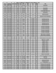
Table 2.3-2 shows the baseline mission parameters as a function of launch date. The<br />
deterministic ∆V requirement has been minimized, but varies from 236 to 260 m/s over<br />
the launch period. Deep space maneuvers have been scheduled to fall outside of solar<br />
conjunction periods (defined as Sun-Earth-Probe angles < 3°) and interstellar dust<br />
collection periods.<br />
The injection and Earth return times are consistent with the launch and landing site<br />
constraints. The launch profiles are in accordance with the Boeing trajectory analysis<br />
contained in document CDRL C37, Contract NAS5-332933, “Detailed Test Objectives<br />
(DTO) Trajectories for the STARDUST Spacecraft Mission”, dated July 1, 1998. The<br />
Earth return time is not exact, but is a best estimate based on LMA 3-D entry analysis.<br />
The error in entry time is not more than a few minutes and will be removed after launch.<br />
The accuracy of the trajectories described in Table 2.3-2 is limited by the accuracy of the<br />
modeling included in the trajectory optimization software (program CATO-STAR).<br />
STARDUST is the first JPL mission where attitude control burns are unbalanced, and<br />
attitude control activity has non-negligible effects on the trajectory design and ∆V<br />
budget. However, the modeling of attitude control activity is incomplete in CATO-<br />
STAR, in that it accounts for perturbations caused only by deadband control, i.e. limit<br />
cycling. The following three items have been intentionally left unaccounted for in<br />
CATO-STAR:<br />
1. The unbalanced ACS forces imparted during periodic slewing of the spacecraft for<br />
communications and maneuvers (about 700 slews). See section 10 for the details of<br />
the total ACS force model.<br />
2. A detailed solar pressure model. Solar pressure is modeled with a single flat plate.<br />
3. A detailed engine performance model. The engine performance parameters (blowdown<br />
system) at each burn are approximate and based on best estimates.<br />
Correction of the errors due to the first two will be made in the trajectory propagation<br />
(ODP) process used by the navigation team. The third error, a small one, will be fixed<br />
prior to launch.<br />
19
The launch specification process used on STARDUST offers simplifications to the<br />
calculation of Delta II/37F ascent burn profiles. Constant C3 (26 km 2 /s 2 ) and constant<br />
burn duration eliminate the need to manage launch vehicle ballast. Further, the same<br />
launch declination is used for several consecutive launch days, thus fixing the Stage II<br />
motor restart time. In all, STARDUST requires only five different launch profiles to<br />
accommodate its 20-day launch period. The daily variations in launch right ascension are<br />
controlled by adjusting the lift-off time.<br />
20
Table 2.3-2 Baseline Mission Parameters vs.Launch Date<br />
Event Quantity 02/06/99 02/07/99 02/08/99 02/09/99<br />
______________________________________________________________________________________________________<br />
Launch Time (UTC) 21:07:24.0 21:04:57.3 21:00:26.2 21:18:02.5<br />
Injection (ET) 21:34:37.4 21:32:10.7 21:27:39.7 21:44:42.4<br />
C3(km^2/s^2) 26.0 26.0 26.0 26.0<br />
DLA (deg) -19.695 -19.695 -19.695 -20.500<br />
RLA (deg) 234.800 235.173 235.026 238.140<br />
Mass (kg) 394.000 394.000 394.000 394.000<br />
______________________________________________________________________________________________________<br />
DSM11 Date 3/10/00 12/24/99 11/20/99 3/10/00<br />
DV (m/s) 71.952 71.940 71.934 71.952<br />
Propellant mass (kg) 13.440 13.440 13.440 13.440<br />
Burn Duration (s) 2100.0 2100.0 2100.0 2100.0<br />
*Burn Declination (deg) -0.652 5.906 4.121 -1.581<br />
*Burn Right Ascension (deg) 242.333 229.129 204.624 237.167<br />
______________________________________________________________________________________________________<br />
DSM12 Date 3/12/00 12/26/99 11/22/99 3/12/00<br />
DV (m/s) 61.247 61.236 61.231 61.247<br />
Propellant mass (kg) 11.164 11.164 11.164 11.164<br />
Burn Duration (s) 2100.0 2100.0 2100.0 2100.0<br />
*Burn Declination (deg) -0.660 6.085 4.499 -1.603<br />
*Burn Right Ascension (deg) 242.663 229.437 205.111 237.564<br />
______________________________________________________________________________________________________<br />
DSM13 Date 3/14/00 12/28/99 11/24/99 3/14/00<br />
DV (m/s) 34.873 38.440 45.713 37.139<br />
Propellant mass (kg) 6.246 6.880 8.168 6.649<br />
*Burn Duration (s) 1324.2 1458.7 1731.8 1409.5<br />
*Burn Declination (deg) -0.668 173.738 4.876 -1.626<br />
*Burn Right Ascension (deg) 242.993 -310.255 205.594 237.960<br />
______________________________________________________________________________________________________<br />
EGA *Date 01/15/01 01/15/01 01/15/01 01/18/01<br />
*Time (ET) 11:01:24.1 11:00:14.3 11:10:11.5 08:03:07.7<br />
*Altitude (km) 5964.5 6002.9 6030.2 4151.0<br />
*B-plane Angle (deg) 144.446 144.218 144.082 148.268<br />
*V infinity (km/s) 6.480 6.480 6.480 6.505<br />
*Mass (kg) 362.213 361.587 360.305 361.812<br />
______________________________________________________________________________________________________<br />
DSM2 Date 03/13/02 06/10/01 06/10/01 03/13/02<br />
DV (m/s) 0.001 0.003 0.003 1.474<br />
Propellant mass (kg) 0.000 0.001 0.001 0.263<br />
*Burn Duration (s) 0.0 0.1 0.1 63.1<br />
*Burn Declination (deg) -90.000 -180.000 -180.000 -4.037<br />
*Burn Right Ascension (deg) -360.000 -360.000 -360.000 204.639<br />
______________________________________________________________________________________________________<br />
DSM31 Date 07/04/03 07/04/03 07/04/03 07/14/03<br />
DV (m/s) 28.484 28.419 28.116 23.014<br />
Propellant mass (kg) 5.041 5.021 4.950 4.071<br />
*Burn Duration (s) 1213.7 1208.9 1191.8 980.1<br />
*Burn Declination (deg) 7.154 7.153 7.078 -0.214<br />
*Burn Right Ascension (deg) 3.892 3.891 3.936 14.379<br />
______________________________________________________________________________________________________<br />
DSM32 Date 07/06/03 07/06/03 07/06/03 07/16/03<br />
DV (m/s) 41.003 41.074 41.215 40.970<br />
Propellant mass (kg) 7.152 7.152 7.152 7.152<br />
Burn Duration (s) 750.0 750.0 750.0 750.0<br />
*Burn Declination (deg) 7.407 7.445 6.367 -0.484<br />
*Burn Right Ascension (deg) 5.758 5.758 5.709 16.311<br />
______________________________________________________________________________________________________<br />
Wild-2 Date 01/02/04 01/02/04 01/02/04 01/02/04<br />
Encounter Time (ET) 19:20:00.0 19:20:00.0 19:20:00.0 19:20:00.0<br />
*V infinity (km/s) 6.120 6.120 6.120 6.124<br />
*Mass (kg) 348.721 348.116 346.906 349.035<br />
z - Earth angle (deg) 19:20:00.0 19:20:00.0 19:20:00.0 0.010<br />
z - Sun angle (deg) 6.120 6.120 6.120 16.764<br />
______________________________________________________________________________________________________<br />
DSM4 Date 02/01/04 02/01/04 02/01/04 02/01/04<br />
Time (ET) 19:20:00.0 19:20:00.0 19:20:00.0 19:20:00.0<br />
DV (m/s) 0.613 0.611 0.740 0.000<br />
Propellant mass (kg) 0.107 0.106 0.128 -0.000<br />
Burn Duration (s) 30.5 30.3 36.6 0.0<br />
*Burn Declination (deg) -3.469 -177.647 -32.609 -90.000<br />
*Burn Right Ascension (deg) 143.582 -36.458 142.391 -180.983<br />
______________________________________________________________________________________________________<br />
Earth Return Date 01/15/06 01/15/06 01/15/06 01/18/06<br />
Time (ET) 09:58:07.1 09:58:07.0 09:58:07.0 09:34:57.6<br />
*V infinity (km/s) 6.418 6.418 6.418 6.449<br />
*B plane angle (deg) -41.049 -41.051 -41.050 -40.835<br />
*Declination (deg) 10.958 10.958 10.959 11.223<br />
*Right Ascension (deg) 207.679 207.679 207.679 205.263<br />
*Mass (kg) 347.953 347.349 346.117 348.366<br />
______________________________________________________________________________________________________<br />
Total DV (m/s) 238.173 241.723 248.952 235.796<br />
______________________________________________________________________________________________________<br />
Note: ET-UTC = 64.185 sec at Launch<br />
21
Table 2.3-2 Baseline Mission Parameters vs.Launch Date (cont)<br />
Event Quantity 02/10/99 02/11/99 02/12/99 02/13/99<br />
______________________________________________________________________________________________________<br />
Launch Time (UTC) 21:19:15.0 21:20:51.3 21:19:15.0 21:20:02.9<br />
Injection (ET) 21:45:54.9 21:47:31.3 21:45:54.9 21:46:42.8<br />
C3(km^2/s^2) 26.0 26.0 26.0 26.0<br />
DLA (deg) -20.500 -20.500 -20.500 -20.500<br />
RLA (deg) 239.429 240.817 241.400 242.586<br />
Mass (kg) 390.000 394.000 394.000 394.000<br />
______________________________________________________________________________________________________<br />
DSM11 Date 3/10/00 3/10/00 3/10/00 3/10/00<br />
DV (m/s) 72.703 71.952 71.951 71.951<br />
Propellant mass (kg) 13.440 13.440 13.440 13.440<br />
Burn Duration (s) 2100.0 2100.0 2100.0 2100.0<br />
*Burn Declination (deg) 0.497 2.771 3.774 5.677<br />
*Burn Right Ascension (deg) 242.394 252.099 231.389 235.429<br />
______________________________________________________________________________________________________<br />
DSM12 Date 3/12/00 3/12/00 3/12/00 3/12/00<br />
DV (m/s) 61.907 61.246 61.246 61.246<br />
Propellant mass (kg) 11.164 11.164 11.164 11.164<br />
Burn Duration (s) 2100.0 2100.0 2100.0 2100.0<br />
*Burn Declination (deg) 0.503 2.800 3.839 5.767<br />
*Burn Right Ascension (deg) 242.757 252.361 231.817 235.850<br />
______________________________________________________________________________________________________<br />
DSM13 Date 3/14/00 3/14/00 3/14/00 3/14/00<br />
DV (m/s) 38.340 47.121 47.254 50.138<br />
Propellant mass (kg) 6.787 8.415 8.438 8.947<br />
*Burn Duration (s) 1438.9 1784.0 1789.0 1896.9<br />
*Burn Declination (deg) 0.509 2.828 3.903 5.856<br />
*Burn Right Ascension (deg) 243.120 252.626 232.244 236.270<br />
______________________________________________________________________________________________________<br />
EGA *Date 01/19/01 01/20/01 01/20/01 01/21/01<br />
*Time (ET) 06:13:57.7 05:11:34.4 14:42:34.3 10:05:08.6<br />
*Altitude (km) 3568.3 2910.5 2744.6 2231.9<br />
*B-plane Angle (deg) 149.508 150.816 151.369 152.468<br />
*V infinity (km/s) 6.523 6.550 6.556 6.583<br />
*Mass (kg) 357.681 360.047 360.025 359.518<br />
______________________________________________________________________________________________________<br />
DSM2 Date 12/19/01 02/08/02 07/05/01 08/17/01<br />
DV (m/s) 0.000 2.105 0.000 0.012<br />
Propellant mass (kg) -0.000 0.373 -0.000 0.002<br />
*Burn Duration (s) 0.0 89.7 0.0 0.4<br />
*Burn Declination (deg) -90.000 30.248 89.993 -90.000<br />
*Burn Right Ascension (deg) -360.000 199.426 0.000 -30.000<br />
______________________________________________________________________________________________________<br />
DSM31 Date 07/14/03 07/14/03 07/14/03 07/14/03<br />
DV (m/s) 20.234 21.343 20.425 19.437<br />
Propellant mass (kg) 3.543 3.757 3.600 3.421<br />
*Burn Duration (s) 853.1 904.6 866.7 823.8<br />
*Burn Declination (deg) -4.099 -12.531 5.580 4.035<br />
*Burn Right Ascension (deg) 15.783 16.853 15.969 14.611<br />
______________________________________________________________________________________________________<br />
DSM32 Date 07/16/03 07/16/03 07/16/03 07/16/03<br />
DV (m/s) 41.361 41.152 41.092 41.131<br />
Propellant mass (kg) 7.152 7.152 7.152 7.152<br />
Burn Duration (s) 1800.0 1800.0 1800.0 1800.0<br />
*Burn Declination (deg) -3.582 -10.529 4.262 3.113<br />
*Burn Right Ascension (deg) 17.630 18.827 17.441 16.354<br />
______________________________________________________________________________________________________<br />
Wild-2 Date 01/02/04 01/02/04 01/02/04 01/02/04<br />
Encounter Time (ET) 19:20:00.0 19:20:00.0 19:20:00.0 19:20:00.0<br />
*V infinity (km/s) 6.124 6.131 6.130 6.135<br />
*Mass (kg) 345.701 347.480 347.990 347.660<br />
z - Earth angle (deg) 0.070 0.130 0.143 0.204<br />
z - Sun angle (deg) 16.824 16.883 16.896 16.958<br />
______________________________________________________________________________________________________<br />
DSM4 Date 02/01/04 02/01/04 02/01/04 02/01/04<br />
Time (ET) 19:20:00.0 19:20:00.0 19:20:00.0 19:20:00.0<br />
DV (m/s) 2.930 0.000 5.802 2.227<br />
Propellant mass (kg) 0.505 -0.000 1.006 0.386<br />
Burn Duration (s) 144.2 0.0 287.3 110.3<br />
*Burn Declination (deg) 20.828 -90.000 -71.777 -41.582<br />
*Burn Right Ascension (deg) 139.302 -141.965 103.798 -220.762<br />
______________________________________________________________________________________________________<br />
Earth Return Date 01/19/06 01/20/06 01/20/06 01/21/06<br />
Time (ET) 09:27:01.6 09:18:56.8 09:18:54.1 09:10:47.1<br />
*V infinity (km/s) 6.469 6.494 6.495 6.524<br />
*B plane angle (deg) -40.758 -40.674 -40.663 -40.588<br />
*Declination (deg) 11.301 11.382 11.398 11.458<br />
*Right Ascension (deg) 204.455 203.644 203.650 202.840<br />
*Mass (kg) 344.526 346.806 346.310 346.597<br />
______________________________________________________________________________________________________<br />
Total DV (m/s) 237.475 244.919 247.770 246.142<br />
______________________________________________________________________________________________________<br />
Note: ET-UTC = 64.185 sec at Launch<br />
22
Table 2.3-2 Baseline Mission Parameters vs.Launch Date (cont)<br />
Event Quantity 02/14/99 02/15/99 02/16/99 02/17/99<br />
______________________________________________________________________________________________________<br />
_<br />
Launch Time (UTC) 19:01:15.5 19:01:42.5 19:02:24.4 19:03:19.6<br />
Injection (ET) 19:30:49.8 19:31:16.7 19:31:58.7 19:32:53.8<br />
C3(km^2/s^2) 26.0 26.0 26.0 26.0<br />
DLA (deg) -16.030 -16.030 -16.030 -16.029<br />
RLA (deg) 220.385 221.483 222.644 223.860<br />
Mass (kg) 394.000 394.000 394.000 394.000<br />
______________________________________________________________________________________________________<br />
_<br />
DSM11 Date 3/10/00 3/10/00 3/10/00 3/10/00<br />
DV (m/s) 71.947 71.947 71.947 71.947<br />
Propellant mass (kg) 13.440 13.440 13.440 13.440<br />
Burn Duration (s) 2100.0 2100.0 2100.0 2100.0<br />
*Burn Declination (deg) -3.632 0.686 5.323 10.075<br />
*Burn Right Ascension (deg) 232.074 233.673 235.109 236.936<br />
______________________________________________________________________________________________________<br />
_<br />
DSM12 Date 3/12/00 3/12/00 3/12/00 3/12/00<br />
DV (m/s) 61.243 61.242 61.242 61.242<br />
Propellant mass (kg) 11.164 11.164 11.164 11.164<br />
Burn Duration (s) 2100.0 2100.0 2100.0 2100.0<br />
*Burn Declination (deg) -3.675 0.693 5.390 10.212<br />
*Burn Right Ascension (deg) 232.528 234.096 235.503 237.285<br />
______________________________________________________________________________________________________<br />
_<br />
DSM13 Date 3/14/00 3/14/00 3/14/00 3/14/00<br />
DV (m/s) 39.794 35.936 35.251 36.655<br />
Propellant mass (kg) 7.120 6.435 6.314 6.563<br />
*Burn Duration (s) 1509.4 1364.3 1338.6 1391.4<br />
*Burn Declination (deg) -3.718 0.701 5.458 10.348<br />
*Burn Right Ascension (deg) 232.980 234.517 235.897 237.634<br />
______________________________________________________________________________________________________<br />
_<br />
EGA *Date 01/10/01 01/12/01 01/13/01 01/14/01<br />
*Time (ET) 20:39:16.2 03:22:12.9 07:16:13.1 10:34:16.3<br />
*Altitude (km) 8801.7 8073.8 7333.2 6604.3<br />
*B-plane Angle (deg) 138.446 140.255 141.705 143.133<br />
*V infinity (km/s) 6.529 6.503 6.492 6.485<br />
*Mass (kg) 361.371 362.054 362.176 361.927<br />
______________________________________________________________________________________________________<br />
_<br />
DSM2 Date 07/16/01 01/12/03 01/22/03 01/22/03<br />
DV (m/s) 4.070 5.889 2.671 3.484<br />
Propellant mass (kg) 0.724 1.048 0.476 0.620<br />
*Burn Duration (s) 174.1 252.0 114.4 149.1<br />
*Burn Declination (deg) 63.881 -58.772 -18.182 42.693<br />
*Burn Right Ascension (deg) -47.245 287.076 270.807 281.540<br />
______________________________________________________________________________________________________<br />
_<br />
DSM31 Date 07/14/03 07/14/03 07/14/03 07/14/03<br />
DV (m/s) 31.225 29.761 28.451 26.862<br />
Propellant mass (kg) 5.497 5.247 5.027 4.743<br />
*Burn Duration (s) 1323.7 1263.3 1210.5 1142.0<br />
*Burn Declination (deg) -0.957 -2.023 -1.814 0.970<br />
*Burn Right Ascension (deg) 14.205 15.156 14.600 15.034<br />
______________________________________________________________________________________________________<br />
_<br />
DSM32 Date 07/16/03 07/16/03 07/16/03 07/16/03<br />
DV (m/s) 41.245 41.173 41.066 41.080<br />
Propellant mass (kg) 7.152 7.152 7.152 7.152<br />
Burn Duration (s) 1800.0 1800.0 1800.0 1800.0<br />
*Burn Declination (deg) 0.712 -0.934 -1.423 -0.040<br />
*Burn Right Ascension (deg) 15.789 16.794 16.497 16.799<br />
______________________________________________________________________________________________________<br />
_<br />
Wild-2 Date 01/02/04 01/02/04 01/02/04 01/02/04<br />
Encounter Time (ET) 19:20:00.0 19:20:00.0 19:20:00.0 19:20:00.0<br />
*V infinity (km/s) 6.129 6.127 6.124 6.122<br />
*Mass (kg) 346.686 347.298 348.214 348.096<br />
z - Earth angle (deg) 0.167 0.179 0.165 0.144<br />
z - Sun angle (deg) 16.588 16.577 16.590 16.611<br />
______________________________________________________________________________________________________<br />
_<br />
DSM4 Date 02/01/04 02/01/04 02/01/04 02/01/04<br />
Time (ET) 19:20:00.0 19:20:00.0 19:20:00.0 19:20:00.0<br />
DV (m/s) 10.017 0.000 0.000 0.000<br />
Propellant mass (kg) 1.728 -0.000 -0.000 -0.000<br />
Burn Duration (s) 493.6 0.0 0.0 0.0<br />
*Burn Declination (deg) 112.650 0.167 0.000 0.007<br />
*Burn Right Ascension (deg) -73.517 0.196 0.000 1.416<br />
______________________________________________________________________________________________________<br />
_<br />
Earth Return Date 01/11/06 01/12/06 01/13/06 01/14/06<br />
Time (ET) 10:27:08.5 10:20:02.8 10:12:53.0 10:05:34.3<br />
*V infinity (km/s) 6.441 6.429 6.421 6.417<br />
*B plane angle (deg) -41.280 -41.218 -41.169 -41.113<br />
*Declination (deg) 10.566 10.683 10.774 10.866<br />
23
*Right Ascension (deg) 210.808 210.045 209.264 208.474<br />
*Mass (kg) 344.293 346.630 347.542 347.413<br />
______________________________________________________________________________________________________<br />
_<br />
Total DV (m/s) 259.541 245.948 240.628 241.270<br />
______________________________________________________________________________________________________<br />
_<br />
Note: ET-UTC = 64.185 sec at Launch<br />
Table 2.3-2 Baseline Mission Parameters vs.Launch Date (cont)<br />
Event Quantity 02/18/99 02/19/99 02/20/99 02/21/99<br />
______________________________________________________________________________________________________<br />
Launch Time (UTC) 19:04:31.4 19:27:43.5 19:29:09.4 19:30:46.8<br />
Injection (ET) 19:34:05.7 19:55:44.9 19:57:10.8 19:58:48.2<br />
C3(km^2/s^2) 26.0 26.0 26.0 26.0<br />
DLA (deg) -16.029 -18.500 -18.500 -18.500<br />
RLA (deg) 225.146 225.838 227.182 228.575<br />
Mass (kg) 394.000 394.000 394.000 394.000<br />
______________________________________________________________________________________________________<br />
DSM11 Date 3/10/00 3/10/00 3/10/00 3/10/00<br />
DV (m/s) 71.946 71.946 71.946 71.946<br />
Propellant mass (kg) 13.440 13.440 13.440 13.440<br />
Burn Duration (s) 2100.0 2100.0 2100.0 2100.0<br />
*Burn Declination (deg) 14.836 -15.472 -10.724 -5.812<br />
*Burn Right Ascension (deg) 238.615 236.247 237.801 239.406<br />
______________________________________________________________________________________________________<br />
DSM12 Date 3/12/00 3/12/00 3/12/00 3/12/00<br />
DV (m/s) 61.242 61.242 61.242 61.242<br />
Propellant mass (kg) 11.164 11.164 11.164 11.164<br />
Burn Duration (s) 2100.0 2100.0 2100.0 2100.0<br />
*Burn Declination (deg) 15.035 -15.691 -10.878 -5.896<br />
*Burn Right Ascension (deg) 238.948 236.611 238.159 239.759<br />
______________________________________________________________________________________________________<br />
DSM13 Date 3/14/00 3/14/00 3/14/00 3/14/00<br />
DV (m/s) 40.231 41.201 39.759 40.282<br />
Propellant mass (kg) 7.197 7.369 7.114 7.206<br />
*Burn Duration (s) 1525.9 1562.3 1508.1 1527.8<br />
*Burn Declination (deg) 15.233 -15.910 -11.032 -5.980<br />
*Burn Right Ascension (deg) 239.280 236.976 238.518 240.111<br />
______________________________________________________________________________________________________<br />
EGA *Date 01/15/01 01/16/01 01/17/01 01/18/01<br />
*Time (ET) 13:16:14.0 16:31:10.1 16:39:19.4 16:04:46.0<br />
*Altitude (km) 5856.8 5209.1 4554.5 3917.3<br />
*B-plane Angle (deg) 144.490 146.181 147.574 148.889<br />
*V infinity (km/s) 6.484 6.483 6.493 6.509<br />
*Mass (kg) 361.293 361.122 361.378 361.286<br />
______________________________________________________________________________________________________<br />
DSM2 Date 01/12/03 02/07/03 02/28/03 03/11/03<br />
DV (m/s) 5.808 0.000 0.000 0.000<br />
Propellant mass (kg) 1.032 -0.000 -0.000 -0.000<br />
*Burn Duration (s) 248.0 0.0 0.0 0.0<br />
*Burn Declination (deg) 60.504 -180.000 -180.000 -180.000<br />
*Burn Right Ascension (deg) 299.217 -360.000 -360.000 -360.000<br />
______________________________________________________________________________________________________<br />
DSM31 Date 07/14/03 07/14/03 07/14/03 07/14/03<br />
DV (m/s) 25.253 23.980 22.999 22.113<br />
Propellant mass (kg) 4.448 4.235 4.066 3.909<br />
*Burn Duration (s) 1070.9 1019.7 979.0 941.2<br />
*Burn Declination (deg) 2.346 3.232 3.946 4.587<br />
*Burn Right Ascension (deg) 15.613 16.006 16.072 16.098<br />
______________________________________________________________________________________________________<br />
DSM32 Date 07/16/03 07/16/03 07/16/03 07/16/03<br />
DV (m/s) 41.167 41.040 40.990 40.982<br />
Propellant mass (kg) 7.152 7.152 7.152 7.152<br />
Burn Duration (s) 1800.0 750.0 1800.0 1800.0<br />
*Burn Declination (deg) 1.019 1.848 2.578 3.238<br />
*Burn Right Ascension (deg) 17.219 17.511 17.560 17.579<br />
______________________________________________________________________________________________________<br />
Wild-2 Date 01/02/04 01/02/04 01/02/04 01/02/04<br />
Encounter Time (ET) 19:20:00.0 19:20:00.0 19:20:00.0 19:20:00.0<br />
*V infinity (km/s) 6.121 6.119 6.120 6.122<br />
*Mass (kg) 347.349 348.438 348.865 348.932<br />
z - Earth angle (deg) 0.116 0.063 0.021 0.026<br />
z - Sun angle (deg) 16.639 16.691 16.733 16.780<br />
______________________________________________________________________________________________________<br />
DSM4 Date 02/01/04 02/01/04 02/01/04 02/01/04<br />
Time (ET) 19:20:00.0 19:20:00.0 19:20:00.0 19:20:00.0<br />
DV (m/s) 0.000 8.414 8.296 7.487<br />
Propellant mass (kg) -0.000 1.460 1.441 1.301<br />
Burn Duration (s) 0.0 416.9 411.6 371.6<br />
*Burn Declination (deg) 0.000 -69.336 -109.420 -70.990<br />
*Burn Right Ascension (deg) 0.000 111.907 287.970 106.505<br />
______________________________________________________________________________________________________<br />
Earth Return Date 01/15/06 01/16/06 01/17/06 01/18/06<br />
Time (ET) 09:58:06.8 09:50:27.3 09:42:44.1 09:34:54.0<br />
*V infinity (km/s) 6.418 6.425 6.435 6.450<br />
24
*B plane angle (deg) -41.051 -40.967 -40.895 -40.821<br />
*Declination (deg) 10.958 11.072 11.160 11.243<br />
*Right Ascension (deg) 207.678 206.886 206.080 205.270<br />
*Mass (kg) 346.665 346.299 346.741 346.946<br />
_____________________________________________________________________________________________________<br />
Total DV (m/s) 245.647 247.823 245.232 244.052<br />
______________________________________________________________________________________________________<br />
Note: ET-UTC = 64.185 sec at Launch<br />
Table 2.3-2 Baseline Mission Parameters vs.Launch Date (cont)<br />
Event Quantity 02/22/99 02/23/99 02/24/99 02/25/99<br />
______________________________________________________________________________________________________<br />
Launch Time (UTC) 19:32:33.3 19:34:26.4 19:42:45.1 19:44:49.7<br />
Injection (ET) 20:00:34.6 20:02:27.8 20:10:20.7 20:12:25.3<br />
C3(km^2/s^2) 26.0 26.0 26.0 26.0<br />
DLA (deg) -18.500 -18.500 -19.150 -19.150<br />
RLA (deg) 230.005 231.463 232.811 234.317<br />
Mass (kg) 394.000 394.000 394.000 394.000<br />
______________________________________________________________________________________________________<br />
DSM11 Date 3/10/00 3/10/00 3/10/00 3/10/00<br />
DV (m/s) 71.946 71.946 71.946 71.946<br />
Propellant mass (kg) 13.440 13.440 13.440 13.440<br />
Burn Duration (s) 2100.0 2100.0 2100.0 2100.0<br />
*Burn Declination (deg) -0.927 3.757 -0.533 3.789<br />
*Burn Right Ascension (deg) 241.049 242.672 242.822 243.078<br />
______________________________________________________________________________________________________<br />
DSM12 Date 3/12/00 3/12/00 3/12/00 3/12/00<br />
DV (m/s) 61.241 61.241 61.241 61.241<br />
Propellant mass (kg) 11.164 11.164 11.164 11.164<br />
Burn Duration (s) 2100.0 2100.0 2100.0 2100.0<br />
*Burn Declination (deg) -0.940 3.811 -0.540 3.841<br />
*Burn Right Ascension (deg) 241.394 243.011 243.179 243.463<br />
______________________________________________________________________________________________________<br />
DSM13 Date 3/14/00 3/14/00 3/14/00 3/14/00<br />
DV (m/s) 42.786 47.179 51.368 56.697<br />
Propellant mass (kg) 7.649 8.426 9.165 10.102<br />
*Burn Duration (s) 1621.7 1786.3 1942.9 2141.8<br />
*Burn Declination (deg) -0.953 3.865 -0.547 3.892<br />
*Burn Right Ascension (deg) 241.740 243.351 -116.463 243.848<br />
______________________________________________________________________________________________________<br />
EGA *Date 01/19/01 01/20/01 01/21/01 01/22/01<br />
*Time (ET) 14:48:45.7 12:50:12.0 10:02:34.5 06:28:10.5<br />
*Altitude (km) 3303.1 2716.5 2157.1 1649.0<br />
*B-plane Angle (deg) 150.153 151.368 152.562 153.587<br />
*V infinity (km/s) 6.529 6.554 6.584 6.616<br />
*Mass (kg) 360.843 360.068 359.330 358.394<br />
______________________________________________________________________________________________________<br />
DSM2 Date 03/19/03 07/26/01 08/17/01 10/01/01<br />
DV (m/s) 0.000 0.000 1.845 0.002<br />
Propellant mass (kg) -0.000 -0.000 0.327 0.000<br />
*Burn Duration (s) 0.0 0.0 78.5 0.1<br />
*Burn Declination (deg) -180.000 -180.000 -43.382 -90.000<br />
*Burn Right Ascension (deg) -360.000 -360.000 171.221 -360.000<br />
______________________________________________________________________________________________________<br />
DSM31 Date 07/14/03 07/14/03 07/14/03 07/14/03<br />
DV (m/s) 21.283 20.463 20.335 17.748<br />
Propellant mass (kg) 3.759 3.607 3.574 3.116<br />
*Burn Duration (s) 905.0 868.4 860.5 750.2<br />
*Burn Declination (deg) 5.154 5.536 4.782 -3.261<br />
*Burn Right Ascension (deg) 16.033 15.712 13.247 15.350<br />
______________________________________________________________________________________________________<br />
DSM32 Date 07/16/03 07/16/03 07/16/03 07/16/03<br />
DV (m/s) 41.016 41.088 41.208 41.226<br />
Propellant mass (kg) 7.152 7.152 7.152 7.152<br />
Burn Duration (s) 1800.0 1800.0 1800.0 1800.0<br />
*Burn Declination (deg) 3.833 4.273 3.818 -3.017<br />
*Burn Right Ascension (deg) 17.524 17.256 15.188 17.223<br />
______________________________________________________________________________________________________<br />
Wild-2 Date 01/02/04 01/02/04 01/02/04 01/02/04<br />
Encounter Time (ET) 19:20:00.0 19:20:00.0 19:20:00.0 19:20:00.0<br />
*V infinity (km/s) 6.126 6.130 6.136 6.140<br />
*Mass (kg) 348.643 348.023 346.994 346.845<br />
z - Earth angle (deg) 0.079 0.138 0.201 0.283<br />
z - Sun angle (deg) 16.833 16.892 16.954 17.036<br />
______________________________________________________________________________________________________<br />
DSM4 Date 02/01/04 02/01/04 02/01/04 02/01/04<br />
Time (ET) 19:20:00.0 19:20:00.0 19:20:00.0 19:20:00.0<br />
DV (m/s) 6.070 4.128 0.006 2.529<br />
Propellant mass (kg) 1.054 0.716 0.001 0.437<br />
Burn Duration (s) 301.1 204.5 0.3 124.9<br />
*Burn Declination (deg) -70.212 -65.645 -90.000 10.523<br />
*Burn Right Ascension (deg) 109.459 120.855 -360.000 140.904<br />
______________________________________________________________________________________________________<br />
Earth Return Date 01/19/06 01/20/06 01/21/06 01/22/06<br />
Time (ET) 09:26:57.6 09:18:55.1 09:10:47.2 09:02:33.3<br />
*V infinity (km/s) 6.470 6.495 6.524 6.559<br />
25
*B plane angle (deg) -40.744 -40.667 -40.591 -40.508<br />
*Declination (deg) 11.321 11.392 11.454 11.518<br />
*Right Ascension (deg) 204.460 203.649 202.838 202.036<br />
*Mass (kg) 346.900 346.615 346.300 345.711<br />
_____________________________________________________________________________________________________<br />
Total DV (m/s) 244.342 246.045 247.949 251.389<br />
______________________________________________________________________________________________________<br />
Note: ET-UTC = 64.185 sec at Launch<br />
26
2.3.2.2 ∆V Budget<br />
The total ∆V budget is summarized in Table 2.3-2.a. It is based primarily on the<br />
maximum total of deterministic maneuvers across the launch period, 260 m/s, and the<br />
estimate of the required statistical trajectory correction maneuvers. Note that the<br />
unallocated ∆V reserve amounts to 37 m/s. The statistical maneuver history for a Feb. 6<br />
launch is shown in Table 2.3-2.b and leads to the allocation of 63 m/s indicated in Table<br />
2.3-2.a.<br />
Table 2.3-2.a ∆V Budget Summary<br />
Deterministic (m/s) Notes<br />
DSMs 260 Three or four DSMs depending on LD. Max of 20-day LP<br />
(2/14).<br />
Launch Window ± 1 min 2 For collision avoidance with space debris etc.<br />
Slew ∆V effects 5 Cost of ACS Slew ∆V when modeled in Navigation software<br />
Return divert 15 For S/C divert away from earth, executed at ~ 4 hrs before entry<br />
Statistical<br />
TCMs (19) 63 See Table 2.3-2.b for representative profile<br />
ACS Modeling Error 10 Cost in ∆V due to the difference between models and actuals<br />
Sub-Totals 355<br />
Reserve 22 Additional 17 m/s available for full propellant load (85 kg)<br />
Total 377 Initial design requirement<br />
Table 2.3-2.b Maneuver History<br />
Maneuver Epoch Execution Date ∆V-95% (m/s)<br />
TCM-1 L + 15 d 21 Feb 99 44.93<br />
TCM-2 DSM-1 10-14 Mar 00 169.80<br />
TCM-3 DSM-1 + 30 d 13 Apr 00 2.86<br />
TCM-4 EP - 60 d 16 Nov 00 0.44<br />
TCM-5 EP - 10 d 05 Jan 01 0.32<br />
TCM-6 EP + 30 d 14 Feb 01 2.74<br />
TCM-7 DSM-2 13 Mar 02 0.75<br />
TCM-8 DSM-3 04-06 Jul 03 69.87<br />
TCM-9 DSM-3 + 7 d 13 Jul 03 1.48<br />
TCM-10 WCA - 30 d 03 Dec 03 2.26<br />
TCM-11 WCA - 10 d 23 Dec 03 1.46<br />
TCM-12 WCA - 2 d 31 Dec 03 2.60<br />
TCM-13 WCA - 18 h 02 Jan 04 2.02<br />
TCM-14 WCA - 6 h 02 Jan 04 1.31<br />
TCM-15 DSM4 (WCA + 30 d) 01 Feb 04 7.52<br />
TCM-16 3rd aphelion 01 Oct 04 0.66<br />
TCM-17 ER - 60 d 16 Nov 05 2.63<br />
TCM-18 ER - 13 d 02 Jan 06 0.36<br />
TCM-19 ER - 1 d 14 Jan 06 0.23<br />
* Analysis completed 11/20/98, corresponds to 2/6 launch, DTO trajectories and PMA LV covariance.<br />
2.3.2.3 Alternate Launch Periods<br />
27
A serendipitous phasing of Earth and Wild-2 for the 2003 apparition presents additional<br />
opportunities to perform the mission at later dates with the resulting mission<br />
characteristics similar to the baseline launch period mission. The two launch<br />
opportunities correspond to 2 + year and 2 - year Earth Gravity Assist trajectory types but<br />
with comet encounter occurring pre-perihelion. The current spacecraft configuration<br />
(fixed solar arrays and HGA) can be preserved exactly, for encounter, if the encounter<br />
date is set at TP-103d. The spacecraft +z-axis (HGA) can remain pointed at Earth at<br />
comet closest approach with an off-sun angle close to 13° versus 17° in the baseline<br />
mission. Likewise, the heliocentric range is 1.88 AU compared to 1.86 AU and the Earth<br />
range is 2.74 AU compared to 2.61 AU. Although the alternate mission performance is<br />
yet to be thoroughly analyzed, it appears that the mass margin is comparable to that of<br />
the baseline mission. These alternate flights would require slightly higher C3’s, but this<br />
is compensated for by lower post launch ∆V. Tables 2.3-3 and 2.3-4 show the specific<br />
mission parameters for these alternate launch periods.<br />
2.3.3 Space Environment<br />
This section contains space radiation and micrometeoroid data generated by JPL for the<br />
STARDUST project. The format of the data is a fairly standard and widely used by<br />
system designers.<br />
2.3.3.1 Ionizing Radiation Fluence and Dose<br />
Fluence: Three sources of natural space charged particles are considered: galactic<br />
cosmic rays, solar winds and solar proton events. The resulting 7-year cumulative proton<br />
and electron integral fluences are shown in Table 2.3-5. The fluence values shown<br />
correspond to a 99% probability level. The rationale for choosing a 99% confidence level<br />
is that the spacecraft may experience a 95% probabilistic size flare every 2.8 years and a<br />
98.7% probabilistic size flare every 7 years according to the JPL solar flare model.<br />
Therefore, it is deemed prudent to adopt the 99% probabilistic confidence level for a 7<br />
year STARDUST mission.<br />
Radiation Dose: The ionizing dose to which the spacecraft is expected to be exposed as a<br />
function of aluminum thickness is shown in Figure 2.3-3. The calculation is made using<br />
Monte Carlo radiation transport code NOVICE and assumes a spherical shell geometry.<br />
These dose-depth data are generated based on the sum of the proton and electron fluence<br />
data listed in Table 2.3-5. This does not include the radiation design margin (RDM)<br />
required to account for other uncertainties associated with the mass distribution,<br />
electronic parts responses and transport calculations. A RDM of 2 is assumed somewhat<br />
arbitrarily based for the most part on past JPL managed missions.<br />
28
Accumulation of Radiation with Time: Radiation fluence as a function of time is<br />
generated to accommodate concerns regarding solar array design. Figure 2.3-4 shows the<br />
accumulated levels of proton and electron fluences at L+380, 1180, 1820, 2090 and 2535<br />
days. These data points correspond roughly to each of three aphelions, Wild-2 encounter<br />
and end of mission.<br />
To expedite practical applications, the complex degradation profile of solar cell<br />
performance due to the above radiation (multiple sources, wide range of energies and<br />
omni-directional) is converted and measured in terms of the equivalent damage caused by<br />
the incidence of a single 1-MeV electron on silicon cells. The equivalent damage<br />
conversion factors are different for different performance parameters: open circuit<br />
voltage (VOC or Pmax) and for short circuit current (ISC). Figure 2.3-5 shows the<br />
resulting equivalent 1-MeV electron fluence behind a coverglass of variable thickness<br />
and are given for solar cell performance parameters VOC and ISC, respectively.<br />
29
Table 2.3-3 STARDUST Alternate-1 Mission Parameters : 2 + yr ∆V-EGA Trajectory<br />
Launch Parameters Earth Return Parameters Wild-2 Enc. Parameters EGA Parameters<br />
LD C3 Dec Ra ∆V 1 AD Vhp Dap Rap Vhb phase(i) 2 phase(o)<br />
2<br />
EGA.D Alt<br />
1999 (km/s) 2 deg deg m/s 2006 km/s deg deg km/s deg deg 2001 km<br />
4/20 27.00 -18.79 308.30 242 5/17 6.322 -3.81 337.86 5.88 103.0 77.0 5/18 20631<br />
4/21 27.00 -18.56 309.23 239 5/17 6.301 -3.96 337.34 5.88 103.0 77.0 5/19 8331<br />
4/22 27.00 -18.33 310.16 237 5/19 6.270 -4.27 336.50 5.88 103.0 77.1 5/20 9215<br />
4/23 27.00 -18.10 311.08 235 5/20 6.244 -4.62 335.57 5.88 102.9 77.1 5/20 10157<br />
2 4/24 27.00 -17.86 311.98 233 5/21 6.224 -4.99 334.57 5.88 102.9 77.1 5/21 11156<br />
0 4/25 27.00 -17.62 312.88 231 5/23 6.212 -5.40 333.48 5.88 102.8 77.2 5/22 12239<br />
4/26 27.00 -17.39 313.75 229 5/24 6.210 -5.83 332.34 5.88 102.8 77.2 5/23 13382<br />
D 4/27 27.00 -17.15 314.61 228 5/26 6.221 -6.28 331.14 5.88 102.8 77.2 5/24 14598<br />
A 4/28 27.00 -16.92 315.43 226 5/27 6.245 -6.77 329.88 5.88 102.8 77.2 525 15883<br />
Y 4/29 26.71 -17.82 312.13 232 5/25 6.216 -6.14 331.52 5.88 102.8 77.2 5/24 14133<br />
4/30 26.72 -17.59 313.01 230 5/27 6.237 -6.62 330.25 5.88 102.8 77.2 5/25 15418<br />
P 5/ 1 26.74 -17.36 313.85 228 5/29 6.272 -7.13 328.95 5.88 102.8 77.2 5/26 16764<br />
E 5/ 2 26.73 -17.29 314.12 227 5/29 6.290 -7.27 328.47 5.89 102.8 77.2 5/26 17686<br />
R 5/ 3 26.74 -17.25 314.27 226 5/30 6.304 -7.35 328.15 5.89 102.8 77.2 5/27 18527<br />
I 5/ 4 26.75 -17.21 314.41 226 5/30 6.319 -7.42 327.81 5.89 102.8 77.2 5/28 19390<br />
O 5/ 5 26.78 -17.17 314.53 225 5/31 6.336 -7.50 327.46 5.90 102.8 77.2 5/28 20267<br />
D 5/ 6 26.82 -17.15 314.62 225 5/31 6.355 -7.59 327.10 5.90 102.8 77.2 5/29 21149<br />
5/ 7 27.00 -17.88 311.91 223 5/30 6.314 -7.40 327.91 5.89 102.8 77.2 5/27 19130<br />
5/ 8 27.00 -17.51 313.31 224 5/31 6.359 -7.61 327.03 5.90 102.8 77.2 5/29 21312<br />
5/ 9 27.00 -17.08 314.87 226 6/02 6.428 -7.88 325.92 5.91 102.9 77.2 5/31 23918<br />
5/10 27.00 -16.58 316.62 234 6/05 6.552 -8.26 324.39 5.94 103.0 77.0 6/03 27237<br />
1. Post launch deterministic ∆V requirement<br />
2. Phase angle , inbound and outbound<br />
30
Table 2.3-4 STARDUST Alternate-2 Mission Parameters : 2 - yr ∆V-EGA Trajectory<br />
Launch Parameters Earth Return Parameters Wild-2 Enc. Parameters EGA Parameters<br />
LD C3 Dec Ra ∆V * AD Vhp Dap Rap Vhb phase(i) phase(o) EGA.D Alt<br />
1999 (km/s) 2 deg deg m/s 2006 km/s deg deg km/s deg deg 2001 km<br />
6/13 26.65 -1.52 356.50 243 5/21 6.228 -4.89 334.86 5.88 102.9 77.1 5/21 15541<br />
6/14 26.65 -1.17 357.30 241 5/22 6.213 -5.35 333.60 5.88 102.8 77.2 5/22 14253<br />
6/15 26.65 -0.82 358.11 239 5/24 6.210 -5.81 332.39 5.88 102.8 77.2 5/23 13055<br />
6/16 26.65 -0.47 358.91 237 5/26 6.220 -6.26 331.19 5.88 102.8 77.2 5/24 11939<br />
2 6/17 26.65 -0.12 359.72 235 5/27 6.241 -6.69 330.07 5.88 102.8 77.2 5/25 10900<br />
0 6/18 26.65 0.23 0.52 234 5/29 6.271 -7.12 328.99 5.88 102.8 77.2 5/26 9942<br />
6/19 26.51 -0.47 358.93 236 5/28 6.255 -6.90 329.53 5.88 102.8 77.2 5/25 10381<br />
D 6/20 26.50 -0.20 359.54 235 5/29 6.283 -7.23 328.67 5.88 102.8 77.2 5/26 9560<br />
A 6/21 26.50 -0.06 359.86 234 5/29 6.293 -7.29 328.40 5.89 102.8 77.2 5/26 8959<br />
Y 6/22 26.49 0.10 0.24 234 5/30 6.305 -7.35 328.12 5.89 102.8 77.2 5/27 8354<br />
6/23 26.65 -1.50 356.53 234 5/28 6.259 -6.96 329.38 5.88 102.8 77.2 5/25 10257<br />
P 6/24 26.65 -1.11 357.44 233 5/29 6.288 -7.26 328.53 5.89 102.8 77.2 5/26 9258<br />
E 6/25 26.65 -0.72 358.34 232 5/30 6.306 -7.35 328.10 5.89 102.8 77.2 5/27 8337<br />
R 6/26 26.65 -0.33 359.25 232 5/30 6.326 -7.45 327.67 5.89 102.8 77.2 5/28 7478<br />
I 6/27 26.65 0.07 0.17 232 5/31 6.348 -7.56 327.24 5.90 102.8 77.2 5/29 6678<br />
O 6/28 26.65 0.47 1.09 233 6/01 6.371 -7.66 326.81 5.90 102.8 77.2 5/29 5931<br />
D 6/29 26.65 0.88 2.02 234 6/01 6.397 -7.76 326.39 5.91 102.8 77.2 5/30 5235<br />
6/30 26.65 1.28 2.96 235 6/02 6.424 -7.86 325.98 5.91 102.8 77.2 5/31 4585<br />
7/01 26.65 1.69 3.89 236 6/03 6.453 -7.96 325.58 5.92 102.9 77.1 6/01 3977<br />
7/02 26.65 2.09 4.83 238 6/03 6.483 -8.06 325.18 5.92 102.9 77.1 6/01 3409<br />
7/03 26.65 2.50 5.77 240 6/04 6.515 -8.16 324.80 5.93 102.9 77.1 6/02 2877<br />
7/04 26.65 2.90 6.71 242 6/04 6.548 -8.25 324.43 5.94 103.0 77.0 6/03 2378<br />
7/05 26.65 3.30 7.65 244 6/05 6.582 -8.34 324.07 5.94 103.0 77.0 6/04 1910<br />
1. Post launch deterministic ∆V requirement<br />
2. Phase angle , inbound and outbound<br />
31
Table 2.3-5 Proton and Electron Integral Fluence Spectra for STARDUST Mission<br />
Proton<br />
Electron<br />
Energy (MeV) Fluence (cm -2 ) Energy (MeV) Fluence (cm -2 )<br />
Solar Event<br />
Total Electron<br />
9.00E-04 1.48E+16 1.00E-03 3.90E+13<br />
1.00E-03 1.26E+16 1.00E-02 3.90E+11<br />
2.00E-03 4.35E+15 1.00E-01 3.90E+09<br />
5.00E-03 1.07E+15 2.00E-01 9.80E+08<br />
1.00E-02 3.70E+14 3.00E-01 4.40E+08<br />
2.00E-02 1.28E+14 4.00E-01 2.50E+08<br />
5.00E-02 3.15E+13 5.00E-01 1.60E+08<br />
1.00E-01 1.09E+13 6.00E-01 1.50E+08<br />
2.00E-01 3.77E+12 7.00E-01 1.50E+08<br />
5.00E-01 9.27E+11 8.00E-01 1.50E+08<br />
1.00E+00 3.21E+11 9.00E-01 1.50E+08<br />
4.00E+00 1.81E+11 1.00E+00 1.50E+08<br />
1.00E+01 7.57E+10 1.25E+00 1.10E+08<br />
3.00E+01 2.90E+10 1.50E+00 9.50E+07<br />
6.00E+01 1.36E+10 1.75E+00 8.30E+07<br />
1.00E+02 7.90E+09 2.00E+00 7.40E+07<br />
2.00E+02 3.70E+09 2.25E+00 6.80E+07<br />
3.00E+02 2.40E+09 2.50E+00 6.30E+07<br />
4.00E+02 1.70E+09 2.75E+00 5.90E+07<br />
5.00E+02 1.40E+09 3.00E+00 5.60E+07<br />
1.00E+03 6.50E+08 3.25E+00 5.40E+07<br />
Cosmic Proton 3.50E+00 5.20E+07<br />
1.00E+00 4.10E+08 3.75E+00 5.00E+07<br />
4.00E+00 4.10E+08 4.00E+00 4.90E+07<br />
1.00E+01 4.10E+08 4.50E+00 4.70E+07<br />
3.00E+01 4.10E+08 5.00E+00 4.50E+07<br />
6.00E+01 4.10E+08 5.50E+00 4.40E+07<br />
1.00E+02 4.10E+08 6.00E+00 4.30E+07<br />
2.00E+02 4.00E+08 6.50E+00 4.20E+07<br />
3.00E+02 3.80E+08 7.00E+00 4.10E+07<br />
4.00E+02 3.60E+08 1.00E+02 3.40E+07<br />
5.00E+02 3.40E+08 1.00E+03 1.30E+07<br />
1.00E+03<br />
2.50E+08<br />
2.3.3.2 Single Event Upsets<br />
Heinrich flux: The environmental data required to address concerns for Single Event<br />
Upsets (SEU) is provided in Figure 2.3-6 in the form a Heinrich flux versus LET (LET =<br />
dE/dX or energy deposition per unit mass at normal incidence). The data are provided<br />
for 99% and 95% magnitude solar flares based on current solar models and also includes<br />
the contributions of 90% galactic cosmic rays. The measurement of flux as a function of<br />
energy deposition eliminates the need to specify specific individual particle species<br />
(protons, alpha particles and heavy ions) and specific energy deposit characteristics. The<br />
figures provide only simple radiation design references as a function of the flux behind a<br />
spherical shield of variable thickness (0-1000 mils) of Aluminum. Actual SEU rate<br />
33
calculations will require more detailed shielding geometries and consideration of long<br />
diagonal path lengths through the sensitive volume of electronic chips.<br />
10 10 10 -5 10 -3 10 -1 10 1 10 3<br />
10 9<br />
10 8<br />
Launch Date : 2/6/1999<br />
Mission: 2536 days<br />
Does not consider RDM<br />
uncertainties.<br />
Total Ionizing Dose (rads)<br />
10 7<br />
10 6<br />
10 5<br />
10 4<br />
10 3<br />
10 2<br />
Spherical Shell Aluminum Shield (mils)<br />
Figure 2.3-3 Radiation Dose vs Shield Depth (Spherical Aluminum Shell)<br />
34
10 17<br />
10 16<br />
10 15<br />
2535d<br />
2090d<br />
1820d<br />
1180d<br />
L+380d<br />
10 14<br />
10 13<br />
10 12<br />
10 11<br />
10 10<br />
10 9<br />
Proton Integral Fluence (cm -2 )<br />
10 8<br />
.0001 .001 .01 .1<br />
1<br />
Energy (MeV)<br />
10<br />
100<br />
1000<br />
Figure 2.3-4.a. Proton Fluence vs Energy as a Function of Time from Launch<br />
10 14<br />
10 13<br />
10 12<br />
10 11<br />
10 10<br />
10 9<br />
10 8<br />
10 7<br />
Integral Fluence (cm -2 )<br />
1180d<br />
L+380d<br />
2535d<br />
2090d<br />
1820d<br />
10 6 .001<br />
.01<br />
.1<br />
1<br />
Energy (MeV)<br />
10<br />
100<br />
1000<br />
Figure 2.3-4.b. Electron Fluence vs Energy as a Function of Time from Launch<br />
35
10 17<br />
10 16<br />
10 15<br />
10 14<br />
10 13<br />
Fluence (cm -2 ) - VOC, PMAX<br />
2535d<br />
2090d<br />
1820d<br />
1180d<br />
L+380d<br />
10 12 10 -4 10 -3<br />
10 -2<br />
Thickness (gm/cm-2)<br />
10 -1<br />
10 0<br />
Figure 2.3-5.a Equivalent 1-MeV Electron Fluence vs Thickness and Time from Launch<br />
for Effects on Open Circuit Voltage or Max Power<br />
10 16<br />
10 15<br />
10 14<br />
10 13<br />
Fluence ( cm -2 ) - ISC<br />
2535d<br />
2090d<br />
1820d<br />
1180d<br />
L+380d<br />
10 12<br />
10 -4 10 -3<br />
10 -2<br />
10 -1<br />
10 0<br />
Thickness (gm/cm -2 )<br />
Figure 2.3-5.b Equivalent 1-MeV Electron Fluence vs Thickness and Time from Launch<br />
for Effects on Short Circuit Current<br />
36
Solar flare contribution is given as the flux at 1 AU with a required 1/r 2 to 1/r 2.5 scaling<br />
factor for other distances from the sun. The galactic cosmic ray (GCR) contribution is<br />
independent of the spacecraft location.<br />
Probability of Large Solar Events: The probability of encountering a 90% to 99%<br />
magnitude solar flare, particularly during the comet flyby, is of interest for the spacecraft<br />
design team. The probabilities are estimated by D.R. Croley (JPL IOM 5052-96-304)<br />
using the model developed by Feynman et al. at JPL. The predicted mean times between<br />
flares of 90%, 95% and 99% magnitude are given in Table 2.3-6. The table also gives the<br />
derived probability of seeing these flares during the 12 hour period around the flyby.<br />
Table 2.3-6 Probability of Large Solar Flares<br />
Flare Magnitude >90% >95% >99%<br />
Mean time (*solar- max years) ~1.4 ~2.8 ~16.9<br />
Probability of occurrence during the<br />
~1E-3 ~5E-4 ~8E-5<br />
12-hrs of the flyby<br />
*Solar-max years=~7 years of ~11 year solar cycle. All of the 7-year STARDUST mission is in the solarmax<br />
years according to the model.<br />
8<br />
10<br />
flare, no shielding<br />
6<br />
10<br />
4<br />
10<br />
2<br />
10<br />
250 mil<br />
36 mil<br />
60 mil<br />
100 mil<br />
0<br />
10<br />
Heavy -Ion Peak Flux (/cm 2/day)<br />
(Omni-Directional)<br />
-2<br />
10<br />
-4<br />
10<br />
-6<br />
10<br />
-8<br />
10<br />
GCR 25 mil<br />
GCR 500 mil<br />
1000 mil<br />
500 mil<br />
-10<br />
10<br />
1 10 100<br />
LET (MeV-cm 2/mg)<br />
JMR 12/10/96<br />
Figure 2.3-6.a Heavy-ion Flux from a 99% Solar Flare at 1 AU and<br />
for Adams’ 90% Worst Case GCR<br />
37
8<br />
10<br />
flare, no shielding<br />
6<br />
10<br />
4<br />
10<br />
2<br />
10<br />
250 mil<br />
36 mil<br />
60 mil<br />
100 mil<br />
0<br />
10<br />
-2<br />
10<br />
-4<br />
10<br />
-6<br />
10<br />
Heavy -Ion Peak Flux (/cm 2/day)<br />
(Omni-Directional)<br />
GCR 25 mil<br />
GCR 500 mil<br />
Shielding is an aluminum sphere of given radius.<br />
-8<br />
10 100 mil of Al = 0.686 g/cm2<br />
500 mil<br />
1000 mil<br />
-10<br />
10<br />
1 10 100<br />
LET (MeV-cm 2/mg)<br />
Figure 2.3-6b Heavy-ion Flux from a 95% Solar Flare at 1 AU and<br />
for Adams’ 90% Worst Case GCR<br />
2.3.3.3 Micrometeoroid<br />
Cumulative micrometeoroid fluence levels as a function of time from Launch is shown in<br />
Table 2.3-7. These selected times correspond approximately to each of the three<br />
aphelions and to the end of mission. The integral fluence is provided as a function of<br />
particle mass. The numbers correspond to 1-sigma levels of the JPL micrometeoroid<br />
environmental model. The 1-sigma uncertainty of the model assumes log-normal<br />
distribution, thus the 2-sigma and 3-sigma levels are 3 and 9 times of the numbers shown.<br />
Table 2.3-7 STARDUST Mission Micrometeoroid Environment<br />
Time: L+376.4 d L+1188.7 d L+2091.4 d L+2533.6 d<br />
MASS (grams) FLUENCE (particles/m 2 )<br />
3.16E-03 9.292E-04 2.340E-03 4.492E-03 4.790E-03<br />
5.62E-03 4.545E-04 1.145E-03 2.198E-03 2.344E-03<br />
1.00E-02 2.223E-04 5.605E-04 1.076E-03 1.147E-03<br />
1.78E-02 1.039E-04 2.621E-04 5.031E-04 5.365E-04<br />
3.16E-02 4.860E-05 1.226E-04 2.353E-04 2.509E-04<br />
5.62E-02 2.273E-05 5.734E-05 1.100E-04 1.173E-04<br />
1.00E-01 1.063E-05 2.682E-05 5.147E-05 5.489E-05<br />
1.78E-01 4.940E-06 1.247E-05 2.393E-05 2.551E-05<br />
3.16E-01 2.296E-06 5.796E-06 1.112E-05 1.186E-05<br />
38
5.62E-01 1.067E-06 2.694E-06 5.170E-06 5.513E-06<br />
1.00E+00 4.960E-07 1.252E-06 2.400E-06 2.563E-06<br />
1.78E+00 2.306E-07 5.822E-07 1.117E-06 1.192E-06<br />
3.16E+00 1.072E-07 2.707E-07 5.194E-07 5.539E-07<br />
5.62E+00 4.983E-08 1.258E-07 2.414E-07 2.575E-07<br />
Fluence units are -- # of particles for that mass and larger integrated over all velocities<br />
2.4 Science Investigation Descriptions<br />
2.4.1 Science Investigation Requirements<br />
The STARDUST science investigations have levied the following requirements on the<br />
design of the mission:<br />
Primary<br />
• Collect 1000 cometary particles of sizes greater than 15 µm in diameter at an<br />
encounter velocity of less than 6.5 km/s and return them to Earth.<br />
Secondary<br />
• Collect interstellar particles for 150 days minimum.<br />
• Provide greater than 65 images of Wild-2, having a resolution of at least 67 µradians<br />
per pixel, taken within 2000 km of the comet nucleus through selected filters.<br />
• Provide in-situ particle analysis during comet coma flythrough for resolving abundant<br />
elements in cometary solids.<br />
Tertiary<br />
• Provide in-situ particle analysis for interstellar dust.<br />
• Collect comet coma molecules and return them to Earth.<br />
• Conduct dynamic science to measure dust mass fluence, large particles and comet<br />
mass upper limit.<br />
• Provide dust flux measurements of 10 -9 g to 1g particles.<br />
To further understand how these requirements will be met, the following sections<br />
describe in more detail the science environments experienced during the mission.<br />
2.4.2 Comet Wild 2<br />
2.4.2.1 Orbit<br />
39
The orbit of comet Wild-2 was drastically altered in 1974 by Jupiter when it came to<br />
within 13 Jupiter radii of the planet. As a consequence, its perihelion distance has been<br />
decreased from 5.0 to 1.6 AU. The current ephemeris of Wild-2 is based on 709<br />
observations during the 1983-1977 interval. The current best estimate of the orbital<br />
elements of Wild-2 and the position uncertainty (1-σ) near the STARDUST spacecraft<br />
encounter time (taking into consideration future ground based observations) are<br />
summarized in Tables 2.4-1 and 2.4-2 [source: Orbit Update and Ephemeris Files for<br />
Comet 81P/Wild-2, Yeomans, et. al., JPL-IOM 312.F-98-045, July 31, 1998].<br />
Table 2.4-1 Current Best Estimate of Wild-2 Orbital Elements<br />
Orbital Element (1)<br />
Value<br />
Perihelion Date, Tp 26 September 2003<br />
Orbital Period<br />
6.38455254 years<br />
Eccentricity, e 0.540111700<br />
Inclination, i 3.2426206°<br />
Longitude of the Ascending <strong>Node</strong>, Ω 136.1556471°<br />
Argument of Perihelion, ω 41.7735089°<br />
(1) Earth Ecliptic and Equinox of J2000<br />
Table 2.4-2 Projected Position Uncertainty of Comet Wild-2 at Encounter<br />
Component<br />
Value (km, 1-σ)<br />
δR 1055<br />
δT 65<br />
δS 1093<br />
where: R - position along sun-comet line, T - position normal to comet orbit plane<br />
S - perpendicular to R and T in comet orbit plane<br />
2.4.2.2 Nucleus and Coma<br />
Empirical fit to the light curve of comet Wild-2 in 1978 and 1984 gives the following<br />
power law:<br />
M v = 6.7 + 5*log(∆) + 14.62*log(R)<br />
where: M v is visual magnitude<br />
∆ is S/C - comet range (AU)<br />
R is sun - comet range (AU)<br />
In anticipation of a less bright appearance of Wild-2 in 2003, a modified power law fit,<br />
given below, is used for planning the mission:<br />
M v = 7.5 + 5*log(∆) + 15*log(R)<br />
The physical characteristics (size/shape/rotation) of the comet are not well known. For<br />
the purposes of mission planning, a nucleus radius of 2.0 km and a coma radius of<br />
100,000 km are assumed.<br />
40
The proposed 2 km nucleus radius is based on the yet to be published, eight years of data<br />
on P/Wild-2 (provided by Dr. Karen Meech) which was gathered using telescopes up and<br />
including the world’s largest, the 10m Keck reflector. These data easily show that Wild-<br />
2 is active out to 4.5 AU both pre- and post-perihelion. There are 13 first quality points<br />
(positive identification, no evidence of clouds, proper subtraction of other stars in the<br />
reduction aperture, etc.) taken at heliocentric distances greater than 4.5 AU. Ray<br />
Newburn has reduced these to a radius by using a geometric albedo of 0.04 and a phase<br />
function of 0.035 mag/deg. By grouping the data points (averaging points taken within<br />
30 minutes of each other), he finds the following:<br />
Table 2.4-3 P/Wild-2 Nucleus Radius Observation Reduction<br />
Heliocentric Distance (AU) No. of points Mean Radius (km)<br />
4.688 1 2.384<br />
4.764 2 2.009<br />
4.769 4 2.117<br />
4.974 3 1.898<br />
5.025 3 2.037<br />
Source: Private communication from R. Newburn<br />
Note that the single point nearest to the sun, at 4.688 AU, results in the largest radius.<br />
This could be a rotational or statistical effect, but it may also indicate residual activity.<br />
In any case, the average of the remaining 12 points is 2.015 km. The variation from<br />
1.900 to 2.100 km is probably a rotational effect.<br />
It is anticipated that there will be a separation between the center-of-brightness and the<br />
center-of-mass of the comet. An 800 km separation was seen for Halley at 1 AU, but for<br />
an order of magnitude less active comet such as Wild-2, much less separation (~100 km<br />
or less) is suspected. However, photometric model data appears to indicate that the<br />
difficulty for navigation or imaging may be removed at about 10 million km, by imaging<br />
the comet in continuum.<br />
2.4.2.3 Dust Environment<br />
The current best estimates of the dust flux at comet closest approach and the dust fluence<br />
referred to a solar distance of 1.86 AU at TP+98.5 days are shown in Table 2.4-4. For<br />
comparison, the table also contains the dust model documented in the Flight Systems<br />
Requirements Document. The FRSD model was used early during the development<br />
phase design of the spacecraft whipple shields.<br />
The current dust model incorporates information obtained from observations of Wild-2<br />
taken during 1997. It is an extrapolation from Halley comet data with the following<br />
model parameter assumptions:<br />
• Particle size distribution = McDonnell Four slope particle size distribution = -3.65<br />
• Nucleus Radius = 2.0 km, with 40% surface activity<br />
41
• Dust density = Nucleus density = 1000 kg-cm -3<br />
• Mean dust albedo = 0.04<br />
• Water production = 8.37x10 27 mol/s<br />
• Total gas production = Additional 20% of mass 44<br />
• Interpolated Continuum Strength Ap(λ)/s = 5.75 meters<br />
The data that is shown in Table 2.4-4 can be extrapolated to different closest approach<br />
distances by assuming a spherical 1/r 2 particle distribution. It can be readily shown that<br />
the fluence is proportional to 1/D, where D is the closest approach distance.<br />
The table shows that for the nominal closest approach of 150 km the total number of<br />
comet dust particles (diameter > 15 µm) collected will be about 2,700 given the collector<br />
area of 0.104 m 2 . Recall the science requirement for collection of 1000 particles of sizes<br />
greater than 15 µm in diameter. The size requirement enables analysis of the particles by<br />
a variety of sophisticated techniques available in laboratories from a broad spectrum of<br />
the science community. The quantity requirement provides a sufficient number of<br />
samples for a statistically valid sampling of the various particle types, plus sufficient<br />
material to allow for handling and destructive analysis losses.<br />
Table 2.4-4 Wild-2 Dust Model (assuming 150 km flyby @ 6.1 km/s)<br />
Science Model (Phase D #2)<br />
FSRD Model<br />
Size Range Flux @ closet<br />
Size Range<br />
(Radius) approach (#/m 2 /s) Fluence (#/m 2 )<br />
(Radius) Fluence (#/m 2 )<br />
0.1 - 0.4 µm 1.27E6 9.83E7 0.1 - 0.4 µm 1.84E9<br />
0.4 - 0.7 µm 2.24E5 1.73E7 0.4 - 1.0 µm 1.62E8<br />
0.7 - 1.0 µm 9.79E4 7.56E6 1.0 - 2.0 µm 3.08E7<br />
1.0 - 2.0 µm 7.97E4 6.16E6 2.0 - 5.0 µm 5.81E6<br />
2.0 - 7.5 µm 1.13E4 8.73E5 5.0 - 10 µm 3.21E5<br />
7.5 - 10 µm 1.25E2 9.65E3 10 - 15 µm 3.05E4<br />
10 - 20 µm 7.94E1 6.13E3 15 - 20 µm 7.19E3<br />
20 - 50 µm 1.05E1 8.14E2 20 - 50 µm 4.72E3<br />
50 - 100 µm 9.41E-1 7.27E1 50 - 100 µm 2.68E2<br />
0.1 - 0.2 mm 6.37E-1 4.92E1 0.1 - 0.2 mm 6.34E1<br />
0.2 - 0.5 mm 5.32E-1 4.11E1 0.2 - 0.5 mm 2.31E1<br />
0.5 - 1.0 mm 8.78E-2 6.78 0.5 - 1.0 mm 4.03E0<br />
1.0 - 2.0 mm 1.40E-2 1.08 1.0 - 2.0 mm 5.50E-1<br />
2.0 - 5.0 mm 2.42E-3 1.87E-1 2.0 - 5.0 mm 6.90E-2<br />
5.0 - 10.0 mm 1.97E-4 1.52E-2 5.0 - 10.0 mm 3.80E-3<br />
10 - 48 mm 3.67E-5 2.83E-3 10 - 20 mm 4.50E-4<br />
Total 1.302E8 20 - 50 mm 5.61E-5<br />
50 - 104 mm 3.15E-6<br />
Total 2.04E9<br />
The dust shield, with a total area of approximately 2.05 m 2 , is designed to stop a 1 cm<br />
diameter (1 g) particle at the encounter velocity. Using the data in the table, it is<br />
determined that the risk of spacecraft puncture due to particles greater than 1 cm is less<br />
than 5.8E-3.<br />
42
The particle size and number distribution of the current science model shown in Table<br />
2.4-4 incorporates the observations made during the appearance of Wild-2 in 1997.<br />
However, the hazard predictions based on this model is still considered to be speculative.<br />
The mission plan includes a real time hazard assessment, on approach to the comet, and<br />
an adjustment of the flyby distance at E-2 days, if necessary.<br />
2.4.3 Interstellar Dust Particle (ISP) Sizes, Impact Velocity<br />
and Direction<br />
Reports made from 1993 to 1995 by the Ulysses and Galileo dust experiment team<br />
suggested that the upstream speed and direction of interstellar dust particles in ecliptic<br />
latitude and longitude were within a range of (26 km/s, 2.5° ±6°, 252° ±6) to (30<br />
km/s,10°±10°, 280°±30°). The former, an earlier conjecture, indicated the dust stream to<br />
be in the general direction of the interstellar helium gas flow but the latter, a report by<br />
Baguhl, et. al., 1995, suggested a different direction for the dust stream. The<br />
STARDUST project has used both values in the past, but based on a more recent<br />
communications with M. Landgraf (7 Feb 1997), we have adopted a magnitude of 26<br />
km/s and an upstream direction of 7.7° ecliptic latitude and 259° ecliptic longitude. It<br />
does not matter too much which value we adopt because of the magnitude of the<br />
uncertainty. However, it is very important that the ISP collection experiment be designed<br />
in such a manner that the directional information of the collected particles, a key factor in<br />
tracing the particle’s origin, is retained to the extent possible.<br />
The flight paths of ISP’s are modified by the gravity of the sun, the solar pressure and<br />
various other complex processes not well or easily formulated. If one considers only the<br />
simple effects of solar gravity and solar pressure, the velocities of ISP’s of various sizes<br />
can be calculated easily as a function of β, where β is the ratio of the solar pressure to<br />
solar gravity. High β particles (greater than 1) are low density, fluffy ones while low β<br />
particles (less than 1) are dense dark ones.<br />
One to one correspondence between the β group and the particle size cannot be made<br />
without knowledge of individual particle density, shape and radiative parameters. If<br />
some assumptions regarding these parameters are made, it is possible to estimate the<br />
possible range of particle sizes as summarized in Table 2.4-5.<br />
Table 2.4-5 Particle Size Estimate<br />
β Particle Size (µm) β Particle Size (µm)<br />
0.6 0.1 - 0.7 1.4 0.2 - 1.2<br />
1.0 0.1 - 0.9 1.8 0.3 - 2.0<br />
Assumptions: Density = 1-3 g/cc, Reflectivity = 0 - 1<br />
43
2.4.4 Interstellar Dust Science Planning Constraints<br />
The definition of the interstellar particle collection periods and CIDA experiment periods<br />
is deferred to Section 4.2 Interstellar Dust Science. However, it is important to note the<br />
following planning constraints:<br />
• Larger particles are preferred for laboratory analysis. As such, the best orientation<br />
for the collection of interstellar particles is one that tracks the β=1 particle.<br />
• The collector pointing strategy should be consistent. If so, it is expected that the<br />
tracks left in the aerogel will reveal inertial direction information.<br />
• Low impact velocities (less than 25 km/s) are required to assure higher chance of<br />
successful capture of the particles.<br />
• Collection of solar beta population particles is to be avoided to prevent corruption of<br />
the interstellar dust sample. Solar beta particles are assumed to have a velocity of 50<br />
km/s [Martha Hanner] and to be traveling radially outward from the sun. Violation is<br />
this constraint is allowed for communications, TCMs, and spacecraft deadbanding.<br />
• Contamination of the interstellar sample by plume impingement is to be kept to a<br />
minimum. As such, no collection is permitted during DSMs (or TCMs > 20 m/s), but<br />
allowed during other TCMs.<br />
• Collection is allowed with as much as half of the collector grid in the SRC backshell<br />
shadow if required to lengthen the collection periods.<br />
• The CIDA experiment should be discontinued when less than 25% of the total CIDA<br />
field-of-view is exposed to the ISP stream.<br />
44
3.0 Launch Phase (L+0 to L+30 days)<br />
3.1 Overview<br />
The launch phase begins at the launch vehicle lift-off and ends with the completion of the<br />
activation and checkout of most of the spacecraft subsystems. Included in this phase are<br />
spacecraft separation from the launch vehicle, establishment of attitude and<br />
communications, tracking of the spacecraft and the execution of the first trajectory<br />
correction maneuver (TCM-1) to correct the injection error. The duration of this phase is<br />
30 days.<br />
The spacecraft trajectory for this phase is shown in Figure 3.1-1. This plot shows the<br />
path of the spacecraft in an Earth-sun fixed coordinate system for the first day of the<br />
baseline launch period. Subphases are defined in Table 3.1-1. A trajectory data set<br />
containing the following parameters can be found in Section 9.2:<br />
Earth-Probe Range<br />
Sun-Earth-Probe Angle<br />
Sun-Probe-Earth Angle<br />
Moon-Probe Range<br />
Sun-Moon-Probe Angle<br />
Sun-Probe-Moon Angle<br />
1400<br />
50<br />
S,T (1E3 km)<br />
1200<br />
1000<br />
800<br />
600<br />
400<br />
Earth Centered<br />
RS plane = Earth Ecliptic<br />
R = Radial direction (Sun to Earth)<br />
S = Circumferential (Orthogonal to R<br />
along Earth velocity vector)<br />
T = Out-of Plane component<br />
L to L+72 hrs<br />
S<br />
S (1E3 km)<br />
40<br />
30<br />
20<br />
10<br />
0<br />
-10<br />
To<br />
Sun<br />
Earth<br />
S<br />
Time tics: 30 min,<br />
Shadow<br />
200<br />
0<br />
To<br />
Sun<br />
T<br />
-20<br />
-30<br />
-40<br />
-200<br />
-1400 -1200 -1000 -800 -600 -400 -200 0 200<br />
R (1E3 km)<br />
-50<br />
-50 -40 -30 -20 -10 0 10 20 30 40 50<br />
R (1E3 km)<br />
Figure 3.1-1 Launch Phase Spacecraft Trajectory<br />
Table 3.1-1 Launch Phase Subphase Definition<br />
Mission Phase Sub-Phases Time (L+days) Duration<br />
(days)<br />
45
Launch<br />
Initial Acquisition<br />
TCM-1<br />
Activation and Checkout<br />
0 - 30<br />
0 - 1<br />
15<br />
1 - 30<br />
30<br />
1<br />
-<br />
29<br />
3.2 Initial Acquisition Subphase<br />
The initial acquisition subphase includes all activities from launch vehicle liftoff to<br />
completion of Deep Space Network (DSN) acquisition. Although one complete day is<br />
allocated for this activity, selection of the short coast launch option allows these activities<br />
to be completed within three hours of launch.<br />
Prior to liftoff (L/O), the spacecraft is powered on via launch vehicle umbilical power at<br />
L/O-240 minutes. The spacecraft is transferred to internal battery power at L/O-4<br />
minutes. At this time the spacecraft is electrically configured for initial cruise mode with<br />
the exception that solar panels are not deployed and the solid-state power amplifier<br />
(SSPA) is off.<br />
The activities from liftoff to spacecraft separation are summarized in Table 3.2-1 and<br />
illustrated in Figure 3.2-1. It should be noted that the numbers presented are specific to a<br />
February 6 launch date, but are typical of other launch dates. However, the specific<br />
numbers are provided for illustrative purposes only and are subject to change as mission<br />
plans mature.<br />
Table 3.2-1 Injection Activities<br />
Event L/O+(sec) (min) Comments<br />
PRE-LAUNCH<br />
1 Spacecraft power ON -86400.0 -1440.0 Latch Valves Closed & System<br />
Wet; EPS, C&DH, Rcvr, & DST<br />
powered<br />
2 Switch to internal power –240.0 -4.0 On batteries<br />
3 Liftoff 0.0 0.0<br />
PRE-SEPARATION<br />
4 Power on Prop Heaters 241.0 4.0 1 lb thrusters, valve, line, tank<br />
5 Main engine cutoff (MECO) 264.0 4.4<br />
6 Stage II ignition 277.7 4.6<br />
7 9.5 ft fairing separation 284.0 4.8<br />
8 First Stage II cutoff (SECO 1) 597.3 10.0<br />
9 Enter Solar Eclipse 902.0 15.0 02/06/99 launch<br />
10 Restart Stage II 1309.8 21.8<br />
11 SECO 2 1414.0 23.6<br />
12 Stage II separation 1467.0 24.5<br />
13 Power on IMU 1485.0 24.8 sep - 2 min, earliest across LP<br />
14 Stage III ignition 1504.0 25.1<br />
15 Stage III burnout 1569.3 26.2<br />
16 Spacecraft separation 1639.0 27.3 Assumes 69.7 seconds coast<br />
17 Open Latch Valves 1640.0 27.3 sep + 1 sec<br />
18 Deploy LV Stage III Yo 1642.0 27.4<br />
DESPIN<br />
46
19 Start S/C despin 1643.0 27.4 delayed to gain sep distance<br />
20 Complete despin 1764.0 29.4 rates < 0.2 deg/s<br />
21 Power on Star Camera 1764.0 29.4<br />
22 Begin attitude acquisition 1764.0 29.4<br />
23 Primary string to 1 lb thrusters 1883.0 31.4<br />
24 Disarm thrusters 1884.0 31.4 No torques during SA deploy<br />
Table 3.2-1 Injection Activities (cont.)<br />
Event L/O+ (sec) (min) Comments<br />
SOLAR ARRAY DEPLOY<br />
25 Start Solar Array Deploy 1885.0 31.4<br />
26 End Solar Eclipse 2231.0 37.2 02/06/99 launch<br />
27 Complete Solar Array Deploy 2785.0 46.4 15 min alloc,
Stage II ignition<br />
t=277.5 s<br />
h=66.4 nmi<br />
v=18,315 fps<br />
MECO<br />
t=264.0 s<br />
h=61.8 nmi<br />
v=18,314 fps<br />
Fairing Jettison<br />
t=284.0 s<br />
h=68.5 nmi<br />
v=18,383 fps<br />
SECO 1<br />
t=597.3 s<br />
h=102.0 nmi<br />
v=25,568 fps<br />
SRM Burnout<br />
t=63.1 s<br />
h=10.9 nmi<br />
v=3,480 fps<br />
SRM Jettison: Set 1 Set 2<br />
t (s)= 66.0 67.0<br />
h (nmi)= 11.8 12.2<br />
v (fps)= 3,520 3,538<br />
Orbit<br />
100.0 nmi circular<br />
28.44 deg inclination<br />
Data shown corresponds to DTO<br />
profile for 2/06/96, but is<br />
typical for other launch dates.<br />
Liftoff - 1.36 g's<br />
SRM impact<br />
Figure 3.2-1.a Launch Vehicle Boost Profile<br />
SECO 2<br />
t=1,414.0 s<br />
h=96.3 nmi<br />
v=29,703 fps<br />
Stage II/III<br />
separation<br />
t=1,467.0 s<br />
Stage III ignition<br />
t=1,504.0 s<br />
h=102.2 nmi<br />
v=29,666 fps<br />
Stage II restart<br />
t=1,309.8 s<br />
h=99.1 nmi<br />
v=25,581 fps<br />
Data shown corresponds to DTO<br />
profile for 2/06/96, but is<br />
typical for other launch dates.<br />
Stage III burnout<br />
t=1,569.3 s<br />
h=120.9 nmi<br />
v=39,745 fps<br />
C3=26.0 km 2 /s 2<br />
DEC=-19.695 deg<br />
RA=234.89337 deg<br />
Spacecraft<br />
separation<br />
t=1,639.0 s<br />
h=175.5 nmi<br />
v=39,497 fps<br />
Figure 3.2-1.b Spacecraft Orbit Injection Profile<br />
3.3 Activation and Checkout Subphase<br />
48
After completion of the initial acquisition subphase, the spacecraft is essentially at a<br />
known attitude with communications having been established. At this point the flight<br />
team begins a characterization and calibration period of the majority of the spacecraft<br />
subsystems. In addition, attitude control maneuvers will commence to maintain the<br />
desired attitude. Communication during this period is near continuous.<br />
Key subsystem performance tests will be conducted early in the checkout phase. Table<br />
3.3-1 provides a summary of the subsystem checkout plan. Again it is noted that specific<br />
numbers are provided for illustrative purposes only and are subject to change.<br />
Table 3.3-1 Subsystem Checkout Plan<br />
Subsystem Activity Time Risk / Impact Data Return<br />
ACS Determine if Star<br />
Camera performance can<br />
maintain 15° deadband<br />
L to<br />
L+14 d<br />
Reliance on IMU for<br />
attitude knowledge.<br />
Impacts power at<br />
Star Camera images,<br />
attitude knowledge<br />
information<br />
aphelion<br />
Telecom Verify HGA<br />
L to Less data return thru use Nominal telemetry<br />
Navigation<br />
Camera<br />
(see below)<br />
CIDA<br />
DFMI<br />
SRC<br />
performance<br />
Perform series of<br />
calibrations, includes<br />
Scan Mirror<br />
Verify CIDA is<br />
functional<br />
Verify DFMI is<br />
operational<br />
Verify SRC latches are<br />
operational<br />
L+90 d<br />
L+4 d to<br />
L+18 d<br />
of MGA.<br />
Unable to obtain<br />
calibrated optical<br />
navigation data<br />
L+5 d Unable to collect CIDA<br />
data<br />
L+18 d Unable to collect DFMI<br />
data<br />
L+90 d Minimal probability<br />
SRC fails to open at first<br />
ISP collection<br />
Nav Camera images<br />
(window<br />
& compress)<br />
CIDA data<br />
DFMI data<br />
Latch telemetry<br />
indicating open<br />
The first trajectory correction maneuver (TCM-1) is performed at L+15 days to correct<br />
injection errors. At completion of this maneuver, the spacecraft will be ready for the<br />
long cruise period that lies ahead.<br />
Within the Activation and Checkout subphase, it is desirable to verify the performance of<br />
the Navigation Camera, the Star Cameras, the pointing mirror, the periscope, the Attitude<br />
Control System (ACS) and the navigation flight software algorithms of centroiding,<br />
windowing and compression, all of which will be heavily used during encounter<br />
operations. Table 3.3-2 provides a summary of the current imaging plans for the launch<br />
phase.<br />
Table 3.3-2 Launch Phase Imaging Plan<br />
Time<br />
L+4<br />
days<br />
L+18<br />
days<br />
Image Description<br />
no. of<br />
images<br />
bits per<br />
pixel<br />
no. of<br />
filters Comments<br />
Moon Color 3 16 4 PIO-windowed, best efforts basis<br />
depending on launch activities<br />
Mirror pointing, alignment 20 16 1 Pattern matched, windowed<br />
& sensitivity calibration<br />
(nav) (10x10), nominal attitude, tight<br />
deadband<br />
49
Special ‘coming-off-theperiscope’<br />
calibration<br />
10 16 1<br />
(nav)<br />
- same as previous -<br />
3.4 Mission Operations<br />
STARDUST mission operations during the launch phase is comprised mainly of the<br />
checkout and activation of spacecraft subsystems, as well as the first orbit determination<br />
of the spacecraft trajectory in preparation for TCM-1.<br />
Initial tracking of the launch vehicle through spacecraft separation will be handled by<br />
various ground tracking stations operated by the Air Force as well as by Advanced Range<br />
Instrumentation Aircraft (ARIA). A NASA requirement calls for tracking of all powered<br />
launch vehicle flight activities, so ARIA tracking is required through out the injection<br />
burns. Within 30 minutes of separation, Boeing will supply JPL with an injection state<br />
based on tracking and telemetered data from the launch vehicle during the launch<br />
sequence. After separation, tracking will be taken over by the Deep Space Network’s<br />
34M HEF net. Table 3.4-1 summarizes the general mission operations requirements and<br />
activities.<br />
Table 3.4-1 Launch Phase Mission Operations<br />
Mission Operation Description<br />
Communications L+0 to 16 d: 24 hr/d, antenna: LGA<br />
L+16 to 30 d: 8 hr/d, antenna: LGA<br />
Navigation L+15 d: TCM 1<br />
Spacecraft Attitude Time Description angz (°) angy (°) db (°)<br />
L+0 to 30 d constant off-sun -45 180 15<br />
DSN Profile<br />
All 34-m<br />
L+0 to +16 d: 24 h/d<br />
L+16 to +30 d: 2*4 h/d<br />
1. See section 10 for attitude mode definitions.<br />
2. DSN Coverage should alternate between Northern Hemisphere and Southern Hemisphere DSN sites.<br />
3. A*B = A number of tracks at B frequency<br />
50
4.0 Cruise Phases<br />
4.1 Overview<br />
The STARDUST mission has nearly six years of relatively low activity cruise. The<br />
cruise phases are subdivided into Cruise 1 (Earth-Earth), Cruise 2 (Earth-Wild-2), and<br />
Cruise 3 (Wild-2-Earth). Within these phase are embedded the following subphases: ISP<br />
collection, Deep Space Maneuvers (DSM), and Trajectory Correction Maneuvers (TCM).<br />
Other activities that occur during the cruise phases but do not have specific subphases<br />
associated with them are the CIDA and DFMI experiments.<br />
The spacecraft trajectory for this phase is the same as shown in Figure 2.3-1. Cruise<br />
phases and subphases are defined in Table 4.1-1. The Cruise phase data set is considered<br />
the same as the Mission data set and can be found in Section 9.1.<br />
Table 4.1-1 Cruise Phase Subphase Definition<br />
Cruise Phase Sub-Phases Time<br />
(L+days)<br />
Cruise 1 (Earth-Earth)<br />
30 - 649<br />
DSM-1 (TCM 2)<br />
398 - 402<br />
ISP Collection<br />
403 - 469<br />
TCM 3 (DSM-1 + 30 d)<br />
432<br />
Cruise 2 (Earth-Wild-2)<br />
Cruise 3 (Wild-2-Earth)<br />
ISP Collection<br />
DSM-2 (TCM 7)<br />
DSM-3 (TCM 8)<br />
TCM 9 (DSM-3 + 7 d)<br />
TCM 16 (3rd aphelion)<br />
739 - 1691<br />
1267 - 1402<br />
1130<br />
1609 - 1611<br />
1618<br />
1841 - 2445<br />
2063<br />
Duration<br />
(days)<br />
619<br />
5<br />
66<br />
-<br />
952<br />
135<br />
1<br />
3<br />
-<br />
604<br />
-<br />
4.2 Interstellar Dust Science<br />
Interstellar dust collection is concentrated in the part of the trajectory where the<br />
Interstellar dust impact velocity is relatively low (inbound trajectory legs). Collection is<br />
performed only during the first two loops resulting in 201 days of total collection time.<br />
Collection is not performed on the third loop to avoid contamination of the cometary<br />
samples collected during the encounter with Wild-2. CIDA and DFMI operations are<br />
nearly continuous, essentially whenever there is sufficient power to turn the instruments<br />
on. However, prime CIDA periods can be defined as those during which the interstellar<br />
dust stream is made to fall within the field-of-view of the CIDA instrument, while not<br />
violating power availability or conflicting with other important mission activities.<br />
With passive experiments and without the need for stringent attitude control (the<br />
uncertainty in the radiant direction of the interstellar dust could be as large as 30°), these<br />
51
phases are very similar to the standard cruise mode (sun-pointed and maintained to ±<br />
15°). The only exception, however, is that in order to maximize the opportunity to<br />
collect interstellar particles and conduct the CIDA experiment, certain periods of off-sun<br />
pointing are allowed. Also recall that these science opportunities are planned for the β=1<br />
(or reference) particle. These particles are those for which solar pressure and solar<br />
gravity are balanced.<br />
In addition to the science constraints described in Section 2.4.3, a number of spacecraft<br />
constraints are imposed for the planning of interstellar dust science. The following<br />
spacecraft guidelines apply to the design of these experiments:<br />
• Off-sun angles of +z-axis are limited to 15° (absolute) when pointing the +x-axis<br />
(whipple shields) toward the sun and 35° (absolute) when pointing the -x-axis (SRC)<br />
toward the sun. Assume 15° deadbands during ISP collection and CIDA periods,<br />
such that, maximum ‘center-of-deadband’ off-sun limits are 0° and 20°, respectively.<br />
• Off-Earth angles are limited such that Earth must always be kept within one of the<br />
low gain antenna fields-of-view.<br />
• The aerogel grid is to be deployed only once per ISP collection period.<br />
• Science periods should avoid conflicts with other mission phases (Launch, EGA,<br />
Encounter) and key geometrical events (solar conjunction).<br />
4.2.1 Interstellar Particle Collection Subphases<br />
Capture of ISP’s is accomplished via a passive aerogel collector that is maintained inside<br />
the SRC and deployed only during the Wild-2 encounter and these collection subphases.<br />
As previously stated, the collection subphases are defined via a number of constraints.<br />
The off-sun angle and beta meteoroid constraints in conjunction with the aerogel<br />
collector deployment geometry are the primary geometric factors that define the start and<br />
end of each collection period. In addition, a combination of spacecraft and science<br />
constraints have led to a plan that does not start ISP-1 until after DSM-1 has been<br />
completed (see section 4.2.3 for more detail).<br />
Each ISP collection period is constructed from the implementation of two different<br />
strategies for tracking the spacecraft relative ISP velocity vector. The first strategy is<br />
implemented during the first part of each collection period and involves taking advantage<br />
of the deployment motion (about the wrist joint) of the aerogel grid to track the motion of<br />
the ISP stream in the spacecraft x-z axis plane. The out-of-plane component of the ISP<br />
stream is tracked by yawing (yaw is a rotation about the z-axis) the spacecraft sufficiently<br />
to place the s/c relative ISP stream in the x-z axis plane. The +z-axis of the spacecraft,<br />
and as a result the solar panels, remain oriented toward the sun.<br />
Once the aerogel grid wrist is fully extended it can no longer be used to track the ISP<br />
stream and the second strategy is invoked. The second strategy involves pointing the<br />
spacecraft -x-axis toward the incoming ISP stream. With the grid wrist fully extended,<br />
the vector normal to the grid surface is parallel to the spacecraft x-axis. The strategy is<br />
52
implemented until the off-sun angle is such that the beta meteoriod constraint is violated,<br />
which typically occurs prior to reaching power related off-sun angle constraints.<br />
The ISP schedule is summarized in Table 4.2-1.a. The collection geometry for the first<br />
trajectory loop is illustrated in Figure 4.2-1.<br />
Table 4.2-1.a Interstellar Particle Collection Subphases<br />
Period<br />
Start<br />
(L+days)<br />
End<br />
(L+days)<br />
Duration<br />
(days)<br />
Equivalent Full Grid<br />
Duration (days)<br />
1 403 469 66 66<br />
2 1267 1402 135 127<br />
Total - - 201 193<br />
141°<br />
b<br />
L+403 d<br />
b<br />
i<br />
= to sun<br />
= to Earth (~8° off +z)<br />
= relative beta meteor (~165° off +z)<br />
= relative isp stream (~11.7 km/s)<br />
i<br />
b<br />
L+453 d<br />
b<br />
i<br />
= to sun<br />
= to Earth (~20° off +z)<br />
= relative beta meteor (~165° off +z)<br />
= relative isp stream (~9.9 km/s)<br />
i<br />
i<br />
b<br />
L+469 d<br />
= to sun (~15° off +z)<br />
= to Earth (~37° off +z)<br />
b = relative beta meteor (~165° off +z)<br />
i = relative isp stream (~10.1 km/s)<br />
Figure 4.2-1 Profile of ISP Collection Experiment - Loop 1<br />
Based on a flux model of 13 interstellar particles per meter squared per day, a 0.1 m 2<br />
collection area and 193 days of “full grid” collection time, this schedule provides for the<br />
collection of about 250 interstellar dust particles. However, thus far we have stressed the<br />
collector pointing strategy in terms of the reference ISP’s (β=1), in reality ISP’s of<br />
different dynamic characteristics will impact the aerogel with various speeds and<br />
directions.<br />
Both of these strategies are consistent with the above stated off-sun angle limits. As<br />
previously stated, the maximum allowable ‘center-of-deadband’ off-sun angles, given 15°<br />
deadbands, are 0° and 20°, respectively. The aerogel grid deployment geometry allows<br />
collection to start much earlier than would be possible by a simple off-sun pointing<br />
strategy, especially in light of the 0° +x-axis-to-sun off-sun angle constraint.<br />
To illustrate the characteristics of these collection periods, Figures 4.2-2 through -4<br />
provide the history of impact velocity of the ISP’s during the collection periods,<br />
spacecraft off-sun and off-Earth angles, spacecraft yaw angle, collector deployment<br />
angle, grid exposure, and beta meteoriod impact angle. These same characteristics are<br />
53
presented in tables contained in Appendix D. The spacecraft attitude consistent with the<br />
ISP plan are also listed in Appendix D. The attitude characteristics of these phases of the<br />
mission are summarized with respect to attitude reference planes defined in Table 4.2-<br />
1.b.<br />
Table 4.2-1.b Reference Plane Definitions<br />
Item<br />
SPE Reference<br />
Plane<br />
Orbital<br />
Reference<br />
Plane<br />
Definition<br />
+z axis // r = unit vector from spacecraft to sun<br />
+y axis // n = unit vector of cross product of vector to sun and vector to<br />
Earth, corrected such that ecliptic-z component is positive<br />
+x axis // t = completes the triad<br />
+z axis // r = unit vector from spacecraft to sun<br />
+y axis // n = unit vector of cross product of heliocentric position and<br />
velocity vectors, i.e. orbit angular momentum vector<br />
+x axis // t = completes the triad<br />
15<br />
10<br />
Impact Velocity<br />
Impact Velocity (km/s)<br />
5<br />
0<br />
350 375 400 425 450 475 500 525 550<br />
15<br />
10<br />
5<br />
0<br />
1250 1275 1300 1325 1350 1375 1400 1425 1450<br />
Time (days from Launch)<br />
Figure 4.2-2 ISP Impact Velocity History ( β=1 particle)<br />
Off-sun & Off-Earth angles (deg)<br />
45<br />
30<br />
15<br />
+z-off-sun<br />
+z-off-earth<br />
0<br />
350 375 400 425 450 475 500 525 550<br />
45<br />
30<br />
15<br />
0<br />
1250 1275 1300 1325 1350 1375 1400 1425 1450<br />
Time (days from Launch)<br />
54
Figure 4.2-3.a. Spacecraft +z-axis Off-sun and Off-Earth Angle History<br />
Off-SEP & ORBIT normal angle (deg)<br />
180<br />
150<br />
120<br />
+y-off-SEP-normal<br />
+y-off-ORBIT-normal<br />
90<br />
350 375 400 425 450 475 500 525 550<br />
180<br />
150<br />
120<br />
90<br />
1250 1275 1300 1325 1350 1375 1400 1425 1450<br />
Time (days from Launch)<br />
Figure 4.2-3.b. Spacecraft +y-axis Yaw Angle History<br />
Collector Depolyment Angle (deg)<br />
180<br />
150<br />
120<br />
Collector Angle<br />
Grid exposure<br />
90<br />
350 375 400 425 450 475 500 525 550<br />
180<br />
1.0<br />
0.8<br />
150<br />
0.6<br />
120<br />
0.4<br />
0.2<br />
90<br />
0.0<br />
1250 1275 1300 1325 1350 1375 1400 1425 1450<br />
Time (days from Launch)<br />
Figure 4.2-4.a. Collector Deployment Angle and Grid Exposure History<br />
1.0<br />
0.8<br />
0.6<br />
0.4<br />
0.2<br />
0.0<br />
Fraction of Grid<br />
BETA-collector normal angle (deg)<br />
90<br />
60<br />
BETA-coll-N angle<br />
30<br />
0<br />
350 375 400 425 450 475 500 525 550<br />
90<br />
60<br />
30<br />
0<br />
1250 1275 1300 1325 1350 1375 1400 1425 1450<br />
Time (days from Launch)<br />
55
Figure 4.2-4.b. Beta Meteoriod Impact Angle<br />
4.2.2 CIDA Experiment<br />
The Cometary and Interstellar Dust Analyzer (CIDA) is planned to be operated anytime<br />
permissible. The main restrictions on CIDA experiment periods are off-sun angle<br />
constraints and other mission phases. The CIDA instrument is body fixed and its field-ofview<br />
is pointing toward the spacecraft +x-axis. The prime CIDA periods are defined as<br />
those portions of the mission during which the interstellar dust stream can be made to fall<br />
in the instrument field-of-view (refer back to Section 2.2.2.4).<br />
Similar to the ISP collection periods, the CIDA experiment periods are built from the<br />
implementation of two different strategies for tracking the spacecraft relative ISP<br />
velocity vector. The initial tracking strategy involves pointing the spacecraft +x-axis<br />
toward the incoming ISP stream. The same deadbands (15°) and maximum ‘center-ofdeadband’<br />
off-sun angles, 0° and 20°, as the ISP collection period analysis apply. The<br />
start of the CIDA period is determined by when the ISP stream aligns itself with the +xaxis<br />
of a sunpointed spacecraft. The spacecraft off-sun angle is increased as the +x-axis<br />
is kept aligned with the drifting spacecraft relative ISP stream. This continues until the<br />
maximum ‘center-of-deadband’ off-sun angle, 20°, is achieved. At this point, the second<br />
strategy is invoked, which involves maintaining the maximum off-sun angle and allowing<br />
the ISP stream to drift through the CIDA field-of-view. The experiment is terminated<br />
when less than a quarter of the CIDA target is exposed to the ISP stream. The out-ofplane<br />
component of the ISP stream is once again tracked via a spacecraft yaw.<br />
The geometrically defined CIDA experiment periods are reduced by other mission<br />
activities. The CIDA 1 and CIDA 2 periods currently allow for some quiet time between<br />
the end of important mission phases and the start of CIDA activity (see section 4.2.3 for<br />
more detail). The CIDA 3 period is technically scheduled during the encounter phase,<br />
but is described here for convenience. The start of CIDA 3 is determined by when the<br />
spacecraft is able to establish communications upon exit of the pre-encounter solar<br />
conjunction. Options for starting CIDA 3 during solar conjunction are discussed in<br />
section 4.2.3. The end of CIDA 3 comes when the communications frequency is<br />
increased to 1 track per day in support of the first encounter trajectory correction<br />
maneuver.<br />
The CIDA experiment plan is summarized in Table 4.2-2. The experiment geometry for<br />
the first trajectory loop is illustrated in Figure 4.2-5. An illustration of the characteristics<br />
of these experiment periods are provided in Figures 4.2-6 through 4.2-7. These same<br />
characteristics are presented in tables contained in Appendix D. The spacecraft attitude<br />
consistent with the CIDA plan are also listed in Appendix D.<br />
Table 4.2-2 Interstellar Particle Related CIDA Experiment Periods<br />
Start End Duration Equivalent Full Target<br />
56
Period (L+days) (L+days) (days) Duration (days)<br />
1 45 144 99 52<br />
2 769 914 145 74<br />
3 1703 1747 44 28<br />
Total - - 288 154<br />
L+45 d<br />
= to sun (~15° off +z)<br />
= to Earth (~60° off +z)<br />
i = relative isp stream<br />
L+54 d<br />
= to sun (~20° off +z)<br />
= to Earth (~53° off +z)<br />
i = relative isp stream<br />
i<br />
L+144 d<br />
= to sun (~20° off +z)<br />
= to Earth (~12° off +z)<br />
i = relative isp stream (~35° off +x)<br />
i<br />
i<br />
Figure 4.2-5 Profile of CIDA Experiment - Loop 1<br />
60<br />
Off-sun & Off-Earth angles (deg)<br />
40<br />
20<br />
+z-off-earth<br />
+z-off-sun<br />
0<br />
0 25 50 75 100 125 150 175 200<br />
60<br />
40<br />
20<br />
0<br />
750 775 800 825 850 875 900 925 950<br />
60<br />
40<br />
20<br />
0<br />
1650 1675 1700 1725 1750 1775 1800 1825 1850<br />
Time (days from Launch)<br />
Figure 4.2-6.a. Spacecraft +z-axis Off-sun and Off-Earth Angle History<br />
57
180<br />
Off-SEP & ORBIT normal angle (deg)<br />
150<br />
120<br />
+y-off-SEP-normal<br />
+y-off-ORBIT-normal<br />
90<br />
0 25 50 75 100 125 150 175 200<br />
180<br />
150<br />
120<br />
90<br />
750 775 800 825 850 875 900 925 950<br />
180<br />
150<br />
120<br />
90<br />
1650 1675 1700 1725 1750 1775 1800 1825 1850<br />
Time (days from Launch)<br />
Figure 4.2-6.b. Spacecraft +y-axis Yaw Angle History<br />
x-axis off-ISP angle (deg)<br />
45<br />
30<br />
15<br />
0<br />
+x-off-ISP<br />
FOV exposure<br />
0.2<br />
0.0<br />
0 25 50 75 100 125 150 175 200<br />
45<br />
1.0<br />
0.8<br />
30<br />
0.6<br />
15<br />
0.4<br />
0.2<br />
0<br />
0.0<br />
750 775 800 825 850 875 900 925 950<br />
45<br />
1.0<br />
0.8<br />
30<br />
0.6<br />
15<br />
0.4<br />
0.2<br />
0<br />
0.0<br />
1650 1675 1700 1725 1750 1775 1800 1825 1850<br />
Time (days from Launch)<br />
Figure 4.2-7. ISP off +x-axis Angle and Field-of-View Exposure History<br />
1.0<br />
0.8<br />
0.6<br />
0.4<br />
FOV exposure (fraction of FOV)<br />
4.2.3 Expansion Opportunities for ISP Experiments<br />
58
The ISP collection and CIDA experiment plans are currently defined to allow easier<br />
mission operations and pre-launch mission design. These allowances, based on rigid<br />
ground rules, result in less than optimal collection durations. If desired, these constraints<br />
may be relaxed, but doing so may add operational and mission plan complexity.<br />
ISP Collection #1<br />
The geometrical conditions suitable for starting ISP 1 can be achieved as early as L+355<br />
days, but DSM-1 would interfere with the collection period. A combination of spacecraft<br />
and science constraints have led to the current plan that does not start ISP 1 until after<br />
DSM 1 has been completed.<br />
The location of DSM 1 is dictated, after all trajectory design considerations, by the need<br />
to allow sufficient radiometric tracking to support the implementation of DSM 1.<br />
Radiometric tracking is affected here by a period of solar conjunction that occurs a few<br />
weeks prior to the DSM. Based on the NEAR spacecraft solar conjunction experience,<br />
DSM 1 has been placed at 14 days after the spacecraft has reached a Sun-Earth-Probe<br />
angle of 4 degrees (increasing). For the mission scenario resulting from a launch on the<br />
first day of the launch period, DSM 1 could be scheduled such that ISP 1 would start on<br />
L+395 days. However, to ease pre-launch trajectory development, DSM 1 has been<br />
scheduled to support the latest SEP=4 degree occurrence across the launch period and<br />
ISP 1 is set to start at L+403 days. The possible variation of ISP 1 as a function of<br />
launch date is illustrated in Figure 4.2-8. Notice that not only does the start of the period<br />
change, but so also does the end of the period. The end of the period is constrained by<br />
the beta meteoriod avoidance constraint. After launch, it should be possible, if required,<br />
to adjust the location of DSM 1 according to the actual launch date and flight trajectory<br />
and obtain an earlier start to ISP 1.<br />
59
2/6 launch<br />
Events<br />
Attitude<br />
74 days<br />
DSM-1 (390-394)<br />
SEP < 4°<br />
+30d TCM<br />
360 376<br />
sunpoint: collector steering<br />
364 388<br />
452<br />
50km/s particle<br />
469<br />
20° off-sun<br />
472<br />
2/15 launch<br />
83 days*<br />
Events<br />
Attitude<br />
SEP < 4°<br />
357<br />
DSM-1 (387-391)<br />
+30d TCM<br />
373<br />
sunpoint: collector steering<br />
372 396<br />
459<br />
50km/s particle<br />
475<br />
20° off-sun<br />
478<br />
* calendar days<br />
82 “full grid”<br />
days<br />
2/25 launch<br />
Events<br />
Attitude<br />
SEP < 4°<br />
346<br />
368<br />
DSM-1 (398-402)<br />
384<br />
+30d<br />
TCM<br />
sunpoint: collector steering<br />
371<br />
53 days<br />
438<br />
50km/s particle<br />
456<br />
20° off-sun<br />
459<br />
Time<br />
days from 2/6<br />
265 295 325 355 385 415 445 475 505 535 565 595<br />
calendar date 10/29/99 11/28 12/28 1/27 2/26 3/27 4/26 5/26 6/25 7/25 8/24 9/23<br />
CIDA Experiment<br />
Figure 4.2-8 ISP 1 Variability Across the Launch Period<br />
The CIDA 1 and 2 periods currently allow for some quiet time between the end of<br />
important mission phases, Launch and EGA, respectively, and the start of CIDA activity.<br />
Geometrically, these periods could start as early as L+20 days (vs. +45 days) and L+740<br />
days (vs. +769 days), respectively. However, operationally, these periods are solidly<br />
restricted by the end of the Launch (L+30 days) and EGA (L+739 days) phases.<br />
The baseline CIDA 3 plan does not provide for off-sun attitudes during the pre-encounter<br />
solar conjunction period (SEP < 3° for 75 days). However, without a specific spacecraft<br />
attitude plan, this portion of the CIDA period will be very inefficient due to the attitude<br />
reference to the Sun-Earth-Probe plane (which will be slowly rotating 180° as the<br />
spacecraft passes through solar conjunction). A plan can be developed that includes<br />
sequenced attitude updates during solar conjunction for more efficient tracking of the ISP<br />
stream. The experiment characteristics and associated spacecraft attitudes for<br />
implementation of standard CIDA experiment strategies (+x-axis alignment with ISP<br />
stream, ISP stream within FOV) during this period are presented in Appendix D.<br />
Finally, the start of off-sun attitudes for CIDA 3 is dictated by the spacecraft exit from<br />
the pre-encounter solar conjunction. For planning purposes, ‘exit’ has been defined as a<br />
Sun-Earth-Probe angle of 3 degrees. If operational experience shows that<br />
communications are possible at smaller SEP angles, the CIDA 3 off-sun period could be<br />
initiated earlier than currently scheduled, L+1703 days. To provide some perspective, in<br />
the current trajectory, a Sun-Earth-Probe angle of 2 degrees is achieved at L+1693 days.<br />
60
4.2.4 Mission Operations Considerations<br />
Current mission operations plan to issue a minimum of weekly updates to the spacecraft<br />
attitude and aerogel grid collector angle during ISP collection, and spacecraft attitude<br />
during the CIDA experiment. An intentional lead-lag strategy should be established for<br />
most efficient tracking of the ISP stream. However, the final spacecraft attitude and<br />
collector angle update schedules can be established only after the post launch final uplink<br />
schedule is known. JPL will provide a list of daily spacecraft attitudes and collector<br />
angles (see section 12) from which LMA will build the required lead-lag update<br />
schedule.<br />
4.3 Mission Operations<br />
Mission operations during the Cruise phases are summarized in Tables 4.3-1.a-c. The<br />
operations during these phases drop to the lowest level of the mission. Activities<br />
required are essentially to maintain the spacecraft attitude profile to ensure adequate<br />
reception of solar power, communication with Earth at the scheduled times and tracking<br />
of ISP’s during the collection and CIDA periods. In addition, the spacecraft gathers and<br />
transmits information on spacecraft health as well as the sporadic science data. Imaging<br />
plans during cruise are limited to calibrations and standard camera maintenance. These<br />
plans are described in Table 4.3-2.<br />
Primary activities on the ground are spacecraft subsystem analysis and maintenance, and<br />
the generation of uplink commands. DSN tracking continues using the 34-m HEF<br />
network. Medium Gain Antenna (MGA) tracking is performed to obtain radiometric data<br />
for orbit determination and DSM/TCM formulation. This radiometric data is comprised<br />
of both ranging data and two-way Doppler data (See the Navigation Plan for more<br />
details). Spacecraft mode tracking is performed for telemetry and command. An uplink<br />
frequency of once per month is anticipated, however, commanding will increase during<br />
ISP collection and CIDA periods to allow tracking of the reference particle.<br />
The current request for DSN tracking in support of DSM-1 and its cleanup maneuver,<br />
TCM-3, is reduced from the baseline for TCMs. The power constraint to avoid casting<br />
shadows on the solar arrays with the whipple shields, and sun-Earth geometry during this<br />
phase of the mission would drive a need for large yaw slews (rotation about the z-axis),<br />
160° over 4 hrs, between the ISP collection attitude and the MGA communications<br />
attitude. Given this slew scenario, the daily communication requirement surrounding<br />
TCMs reduces the amount of time available for ISP collection. Two action are taken to<br />
reduce the impact of NAV tracking on spacecraft slewing and on ISP collection time.<br />
The first is to schedule use of the HGA instead of the MGA. The HGA’s tighter<br />
deadband, together with small SPE angles (also coincident with this phase of the<br />
mission), allows the spacecraft to communicate with the Earth without performing a large<br />
61
yaw, while continuing to meet solar array shadow constraints. The second strategy is a<br />
reduction to the amount of daily tracking required to support these maneuvers. Post-<br />
DSM-1 and pre- and post-TCM-3, daily tracking is reduced from 2 weeks to 1 week.<br />
Mission operations are slightly more complex during actual execution of DSM’s and<br />
TCM’s. During the maneuvers, the attitude of the spacecraft is such that solar power and<br />
telemetry will most likely not be available. The rechargeable battery will be the source<br />
of power. The two large DSM’s (1 and 3) cannot be executed in a single burn due to<br />
insufficient battery capacity. The current plan is to implement DSM-1 in three segments<br />
and DSM-3 in two. Each burn is separated by two days to provide sufficient time for<br />
battery recharging. No ∆V updates between each cluster of burns is planned. However,<br />
receipt of telemetry and radiometric data (>1 hr) for burn reconstruction may be possible<br />
during battery recharging.<br />
At solar ranges beyond 2.5 AU, second (L+1014 to 1320) and third (L+1942 to 2219)<br />
aphelion, the spacecraft operational capabilities are power limited such that a full 4 hour<br />
pass may not be supportable. The duration of tracking passes at these solar ranges will<br />
be reduced from 4 hours to the maximum allowable, down to a minimum of 2 hours (if<br />
required) at aphelion. The second DSM and a TCM are scheduled during second and<br />
third aphelion, respectively. A reduced tracking frequency and track duration is imposed<br />
in support of these maneuvers.<br />
Three TCM’s are planned during the cruise phase. Two of them are performed 30 and 7<br />
days after DSM-1 and -3, respectively, to correct execution errors. The third is<br />
performed at third aphelion and provides an opportunity for early targeting of the return<br />
trajectory.<br />
Table 4.3-1.a Cruise Phase Mission Operations<br />
Mission Operation Description<br />
Communications 4 (1) hrs / week, antenna: MGA<br />
4 (1) hrs / month, antenna: HGA, can replace navigation tracking<br />
TCM/DSMs (overlay changes for DSM 1,2 / TCM 3,16 below)-<br />
Two - 4 hr pass/week - MGA Comm, -14 to -28, +14 to +28d<br />
4 hrs /day - MGA Comm, ± 14 d of first/last segments<br />
1 hr / between seg. - HGA Comm, DSMs only - if possible<br />
DSM 1 / TCM 3 (overlap with ISP-1) - overlay changes:<br />
4 hrs /day - HGA Comm, 0 to +7 d, DSM-1<br />
Two - 4 hr pass/week - HGA Comm, +7 d DSM-1 to -7 d TCM 3<br />
4 hrs /day - HGA Comm, -7 to 0 d, TCM 3<br />
Two - 4 hr passes/week - MGA Comm, +7 to +28 d, TCM 3<br />
DSM 2 / TCM 16 (aphelion maneuvers) - overlay changes:<br />
4 (1) hrs / every other day - MGA Comm, ± 14 d<br />
Navigation L+398-402 d: DSM-1 (TCM 2)<br />
L+432 d: TCM 3<br />
L+1130 d: DSM-2 (TCM 7)<br />
L+1609-1611 d: DSM-3 (TCM 8)<br />
L+1618 d: TCM 9<br />
L+2063 d: TCM 16<br />
1. Or maximum allowable at solar ranges greater than 2.5 AU Minimum of 2 hours for radiometric tracking.<br />
Table 4.3-1.b Cruise Phase Mission Operations - DSN Profile<br />
62
Antennas: All 34-m (4)<br />
L+30 to +43d: 2*4 h/w<br />
L+739 to +753d: 4 h/d<br />
L+43 to +370d: 4 h/w<br />
L+753 to +767d: 2*4 h/w<br />
L+370 to +384d: 2*4 h/w L+767 to L+1014: 4 h/w<br />
L+384 to +409d: 4 h/d<br />
L+1014 to +1102d: 4 (1) h/w<br />
L+409 to +425d: 2*4 h/w L+1102 to +1116d: 2*4 (1) h/w<br />
L+425 to +439d: 4 h/d<br />
L+1116 to +1144d: 4 (1) h/ 2d<br />
L+439 to +460d: 2*4 h/w L+1144 to +1158d: 2*4 (1) h/w<br />
L+460 to +621d: 4 h/w<br />
L+1158 to +1320d: 4 (1) h/w<br />
L+621 to +635d: 2*4 h/w L+1320 to +1581d: 4 h/w<br />
L+635 to +649d: 4 h/d<br />
L+1581 to +1595d: 2*4 h/w<br />
L+649 to +739d: EGA<br />
L+1595 to +1632d: 4 h/d<br />
L+1632 to +1646d: 2*4 h/w<br />
L+1646 to +1691d: 4 h/w<br />
L+1691 to +1841d: Encounter<br />
L+1841 to +1942d: 4 h/w<br />
L+1942 to +2035d: 4 (1) h/w<br />
L+2035 to +2049d: 2*4 (1) h/w<br />
L+2049 to +2077d: 4 (1) h/ 2d<br />
L+2077 to +2091d: 2*4 (1) h/w<br />
L+2091 to +2219d: 4 (1) h/w<br />
L+2219 to +2445d: 4 h/w<br />
L+2445 to +2536d: Return<br />
1. Or maximum allowable at solar ranges greater than 2.5 AU Minimum of 2 hours for radiometric tracking.<br />
2. DSN Coverage should alternate between Northern Hemisphere and Southern Hemisphere DSN sites.<br />
3. A*B = A number of tracks at B frequency<br />
Table 4.3-1.c Cruise Phase Mission Operations - Spacecraft Attitude<br />
Time (days) Description angz (°) angy (°) db (°)<br />
L+0 to 30 Launch Phase<br />
L+30 to 45 constant off-sun 22 180 15<br />
L+45 to 54 CIDA tracking - - 15<br />
L+54 to 144 CIDA constant off-sun -20 - 15<br />
L+144 to 369 constant off-sun 0 180 15<br />
L+369 to 403 constant off-sun 0 0 15<br />
L+403 to 453 ISP collector steering - - 15<br />
L+453 to 469 ISP tracking - - 15<br />
L+469 to 649 constant off-sun 0 0 15<br />
L+649 to 739 EGA Phase<br />
L+739 to 744 constant off-sun 20 0 15<br />
L+744 to 769 constant off-sun 0 0 15<br />
L+769 to 780 CIDA tracking - - 15<br />
L+780 to 914 CIDA constant off-sun -20 - 15<br />
L+914 to 1053 constant off-sun 0 180 15<br />
L+1053 to 1267 constant off-sun 0 0 15<br />
L+1267 to 1385 ISP collector steering - - 15<br />
L+1385 to 1402 ISP tracking - - 15<br />
L+1402 to 1523 constant off-sun 0 180 15<br />
L+1523 to 1658 constant off-sun 0 0 15<br />
L+1658 to 1691 constant off-sun 0 180 15<br />
L+1691 to 1841 Encounter Phase<br />
L+1841 to 1965 constant off-sun 0 0 15<br />
L+1965 to 2185 constant off-sun 0 180 15<br />
L+2185 to 2445 constant off-sun 0 0 15<br />
L+2445 to 2536 Return Phase<br />
MGA communications: 7° off +z-axis to Earth 6<br />
HGA communications: +z-axis to Earth 2<br />
1. See section 10 for attitude mode definitions.<br />
Table 4.3-2 Cruise Phases Imaging Plan<br />
Approx no. of bits per no. of<br />
63
Time Image Description images pixel filters Comments<br />
L+150<br />
days<br />
Standard star in Hyades<br />
- solar analog<br />
28 16 7 4 exp / 7 filters, windowed (15x15),<br />
yaw turn, mirror, tight deadband<br />
Zero exposure 3 16 1 windowed (20x20), determine<br />
camera bias (~400 DN)<br />
Photocal w/ lamp on 21 16 7 3 exp / image, same attitude and<br />
windows as ‘standard star’<br />
L+200<br />
days<br />
Stray light test at encounter<br />
conditions<br />
6 16 1<br />
(hi-res)<br />
@ max exposure, 3 @ 0,1 @ 10, 20,<br />
30 degree mirror angle, no ISP<br />
conflict, full frame, SPE same as<br />
L+410,<br />
days<br />
Standard Maintenance<br />
Sequence<br />
10 /ea 16<br />
(8?)<br />
* repeat L+590, 920, 1100, 1410, 1510 days<br />
1<br />
(nav)<br />
encounter (~17 deg).<br />
pattern matched, windowed (10x10),<br />
nominal background attitude, tight<br />
deadband<br />
64
5.0 Earth Gravity Assist Phase (EGA-60 to EGA+30 days)<br />
5.1 Overview<br />
The Earth flyby is performed to provide a gravity assist to the STARDUST spacecraft<br />
and reduce the ∆V requirements of the mission. The flyby changes the orbital period<br />
from 2 years to about 2.5 years. The spacecraft approaches Earth with a velocity of 6.5<br />
km/s from the dark side and recedes back into the dark side having flown by the sunward<br />
side. At closest approach, the altitude, for a 02/06/99 launch, will be 5965 km, but could<br />
be as low as 1649 km depending on the actual launch date of the mission. During the<br />
flyby the Sun-Earth-Probe angle cycles from ~130° to 28° at closest approach to a<br />
minimum of 19° (8 minutes after closest approach) and back up to ~90° toward the end<br />
of the EGA phase. The Earth flyby time is also dependent on the actual launch date. For<br />
planning purposes, the first launch date is assumed which results in a flyby date and time<br />
of 15 January 2001 11:01:24 (ET), or L+708.5 days.<br />
Three special activities are planned for the Earth Gravity Assist (EGA) phase. The first<br />
is a rehearsal or demonstration of the navigation processes required during return to<br />
Earth. This activity is envisioned to be a ground activity only and will not involve the<br />
spacecraft or require any increase in DSN resources. The second is an opportunity to<br />
take Earth-Moon images. The third and final activity is a Dust Flux Monitor Instrument<br />
experiment. Its objective is to collect data on dust particles near Earth perigee, within the<br />
near-Earth magnetosphere. Support of this activity will require the DFMI to be turned on<br />
and for the spacecraft +x-axis to be oriented parallel to the spacecraft velocity vector as<br />
the spacecraft flys through perigee.<br />
As previously mentioned, the Earth flyby contributes substantially to the reduction of ∆V<br />
requirements for STARDUST. As such, an accurate execution of this event is important.<br />
The JPL navigation team has successfully navigated Earth flybys twice for the GALILEO<br />
project and will have done it again for the CASSINI project. No difficulties are<br />
anticipated.<br />
The spacecraft trajectory, again for a 02/06/99 launch, in Earth-sun fixed coordinates for<br />
this phase is shown in Figure 5.1-1. Subphases are defined in Table 5.1-1. A trajectory<br />
data set containing the following parameters can be found in Section 9.3:<br />
Earth-Probe Range<br />
Sun-Earth-Probe Angle<br />
Sun-Probe-Earth Angle<br />
Moon-Probe Range<br />
Sun-Moon-Probe Angle<br />
Sun-Probe-Moon Angle<br />
Table 5.1-1 Earth Gravity Assist Phase Subphase Definition<br />
Mission Phase Subphases Time (L+days) Duration<br />
(days)<br />
Earth Gravity Assist 649 - 739 90<br />
65
(EGA-60d to +30d) TCM 4 (EGA-60 d)<br />
TCM 5 (EGA-10 d)<br />
TCM 6 (EGA+30 d)<br />
649<br />
698<br />
739<br />
-<br />
-<br />
-<br />
2000<br />
50<br />
1500<br />
40<br />
S<br />
30<br />
1000<br />
20<br />
S,T (1E3 km)<br />
500<br />
0<br />
-500<br />
-1000<br />
To<br />
Sun<br />
Earth Centered<br />
RS plane = Earth Ecliptic<br />
R = Radial direction (Sun to Earth)<br />
S = Circumferential (Orthogonal to R<br />
along Earth velocity vector)<br />
T = Out-of-Plane component<br />
EGA-72 to +72 hrs<br />
T<br />
S<br />
T<br />
S,T (1E3 km)<br />
10<br />
0<br />
-10<br />
-20<br />
-30<br />
-40<br />
To<br />
Sun<br />
C/A<br />
Earth<br />
Shadow<br />
T<br />
time tics<br />
1 hr<br />
S<br />
time tics<br />
30 min<br />
-1500<br />
-1500 -1000 -500 0 500 1000 1500 2000<br />
R (1E3 km)<br />
-50<br />
-50 -40 -30 -20 -10 0 10 20 30 40 50<br />
R (1E3 km)<br />
Figure 5.1-1 Earth Gravity Assist Phase Spacecraft Trajectory<br />
5.2 Mission Operations<br />
Mission operations during the EGA phase is summarized in Table 5.2-1. Support<br />
requirements for the special activities of the EGA phase will be developed post-launch, if<br />
required. However, they are expected to fit within the allocated resources. As before,<br />
ground activities are increased during the TCM periods to process radiometric data and<br />
generate the TCM commands. The delivery accuracy for the -10 day TCM is expected to<br />
be 10 km (1-σ). Two other TCM’s are performed during this phase at closest approach -<br />
60 days and +30 days.<br />
Table 5.2-1 Earth Gravity Assist Phase Mission Operations<br />
Mission Operation Description<br />
Communications EGA - 8 hrs /day, within ±14 days<br />
All MGA, except<br />
LGA: L+708-728<br />
TCMs - Two - 4 hr passes week, -14 to -28, +14 to +28d<br />
4 hrs / day, within ± 14 days<br />
Navigation L+649 (EGA-60 d): TCM 4<br />
L+739 (EGA+30 d): TCM 6<br />
L+699 (EGA-10 d): TCM 5<br />
Spacecraft Attitude Time Description angz (°) angy (°) db (°)<br />
66
(see section 10 for L+649 to 668 d constant off-sun 0 0 15<br />
attitude mode L+668 to 704 d constant off-sun 0 180 15<br />
definitions) L+704 to 708 d constant off-sun -17 180 15<br />
L+708 to 709 d constant off-sun -45 0 15<br />
L+709 to 728 d constant off-sun -45 180 15<br />
L+728 to 739 d constant off-sun 20 0 15<br />
MGA communications: 7° off +z-axis to Earth 6<br />
DSN Profile<br />
All 34-m<br />
L+649 to +663d: 4 h/d<br />
L+663 to +685d: 2*4 h/w<br />
L+685 to +695d: 4 h/d<br />
L+695 to +723d: 8 h/d<br />
L+723 to +739d: 4 h/d<br />
1. DSN Coverage should alternate between Northern Hemisphere and Southern Hemisphere DSN sites.<br />
2. A*B = A number of tracks at B frequency<br />
67
6.0 Wild-2 Encounter Phase (E-100 to E+50 days)<br />
6.1 Overview<br />
The most important phase of the STARDUST mission nominally starts 100 days prior to<br />
and ends 50 days after comet encounter (L+1790.9 days). DSM-3, completed during the<br />
Cruise-2 (Earth-Wild 2) phase, at encounter minus 180 days (E-180 d), is the first aim at<br />
Wild-2. Knowledge of the orbital state of Wild-2 at this time will still be based on<br />
ground observations which will have an estimated position uncertainty of about 1520 km<br />
(1-σ). A better estimate of the comet ephemeris is expected at about E-50 d after optical<br />
navigation (OPNAV) has been in operation for some time. (See Navigation Plan<br />
document, SD-76000-100, for more details). Independent of launch date, encounter with<br />
the comet Wild-2 occurs at a reference time of 02 January 2004 19:20:00 ET.<br />
The primary goal of obtaining comet coma samples during the encounter flyby is<br />
accomplished by a navigation plan that delivers the spacecraft with the required<br />
accuracy. It is also necessary to assure the survival of the spacecraft at a reasonable level<br />
of confidence. The spacecraft encounters Wild-2 at 98.5 days past perihelion. At this<br />
point of its orbit, Wild-2 is far from its “peak” active period and it should be relatively<br />
safe for a 150 km closest approach. A risk analysis based on a probabilistic model of the<br />
Wild-2 dust environment is required, however, this exercise is regarded as preliminary<br />
until a time when a better model may be constructed upon approach to the comet. The<br />
current model is based on best estimates. Adjustment of the encounter parameters (flyby<br />
date and distance) is possible if required by mission risk issues. Given the current dust<br />
models, these adjustments are possible without penalizing mission performance.<br />
This mission phase proceeds from an initially slow pace (scale of days) and progresses<br />
gradually to an extremely fast pace (minutes/seconds) centered around the closest<br />
encounter. In order to organize this mission phase in a more orderly way, it is divided<br />
into four subphases: Far Encounter, Near Encounter, Close Encounter and Post<br />
Encounter. The Far Encounter subphase focuses on acquisition of comet and coma<br />
science data. The Near Encounter subphase emphasizes terminal navigation and high<br />
resolution coma and nucleus activities. The Close Encounter subphase is the core science<br />
period of STARDUST. It contains comet dust sample collection and high resolution<br />
nucleus imaging. Finally, the Post Encounter subphase is dedicated to mission<br />
performance assessment and return of stored science data. Five TCM’s are performed on<br />
approach to the comet. The final TCM before encounter is performed at 6 hours from<br />
closest approach and is expected to be implemented only in case of a contingency. These<br />
subphases are further defined in Table 6.1-1.<br />
Encounter activity is not scheduled to start until the spacecraft exits from the preencounter<br />
solar conjunction. For planning purposes, ‘exit’ has been defined as when the<br />
Sun-Earth-Probe angle reaches 3 degrees (increasing). On the current trajectory, this<br />
occurs 88 days prior to closest approach. The encounter phase definition, however, is left<br />
at E-100 days as operational experience may allow a reduction of the 3 degree SEP angle<br />
68
planning value. The end of the encounter phase, E+50 days, is defined to encompass all<br />
possible data return scenarios, and to adequately cover all post-encounter TCM activity.<br />
Table 6.1-1 Wild-2 Encounter Phase Subphase Definition<br />
Mission Phase Sub-Phases Time Duration<br />
Wild-2 Encounter<br />
(E-100d to +50d)<br />
Far Encounter<br />
Near Encounter<br />
Close Encounter<br />
Closest Encounter<br />
Post Encounter<br />
L+1691 - 1841d<br />
E-100 to -1d<br />
E-1d to -5h<br />
E-5 to +5h<br />
E-5 to +5 m<br />
E+5h to +50d<br />
150 d<br />
99 d<br />
19 h<br />
10 h<br />
10 min<br />
50 d<br />
TCM 10 (E-30 d)<br />
TCM 11 (E-10 d)<br />
TCM 12 (E-2 d)<br />
TCM 13 (E-18 h)<br />
TCM 14 (E-6 h)<br />
DSM 4 (TCM 15) (E+30 d)<br />
L+1761 d<br />
L+1781 d<br />
L+1789 d<br />
L+1790 d<br />
L+1791 d<br />
L+1821 d<br />
-<br />
-<br />
-<br />
-<br />
-<br />
-<br />
An abbreviated CIDA 3, described in section 4, is scheduled for the first half of the<br />
encounter phase where imaging and communications activity is minimal. The spacecraft<br />
attitude required to support the CIDA experiment is significantly different from the<br />
desirable communications attitude. As a result, the CIDA experiment is abandoned (E-44<br />
days) once daily navigation tracking (MGA comm) is initiated in support of the first<br />
approach TCM.<br />
The spacecraft trajectory in a Wild-2-sun fixed system for this phase is shown in Figure<br />
6.1-1. Notice that the small out-of-plane component of the spacecraft path indicates that<br />
it is nearly in the comet’s orbital plane. The spacecraft approaches Wild-2 from above<br />
and recedes under the comet orbit plane. The Sun-Wild-2-Probe angle starts at 73°<br />
which is favorable for pre-encounter comet viewing. This phase angle reaches a<br />
minimum approaching 0° near closest approach and rises back up to 107° toward the end<br />
of the encounter phase. The flyby speed is 6.1 km/s and the nominal flyby distance is<br />
150 km on the sunward side. The 3-sigma minimum flyby distance is 120 km when<br />
considering navigation delivery errors. The spacecraft is presented with the dark side of<br />
Wild-2 as it recedes from the comet.<br />
Near the closest encounter, the spacecraft +x-axis is pointed in the spacecraft-Wild-2<br />
relative velocity direction such that the dust shield protects the spacecraft bus and solar<br />
panels. In this flyby configuration, the Earth is located in the direction of the spacecraft<br />
+z-axis (also HGA direction). The selection of TP+98.5d as the encounter date has been<br />
dictated by this encounter geometry which translates into simplicity and mass savings in<br />
69
the installation of the HGA. The sun is 17° off the +z-axis near the encounter which<br />
results in a slight cosine power loss.<br />
Independent of launch date, the comet closest approach time has been established to be<br />
02 January 2004, 19:20 ET, under near-identical sun, Earth, comet and spacecraft<br />
geometries. This time was chosen to allow for scheduling of the comet flyby during the<br />
Goldstone-Canberra DSN viewperiod overlap. The elevation angles for this period of the<br />
mission are illustrated in Figure 6.1-2. An encounter phase overview is provided in<br />
Figure 6.1-3.<br />
50<br />
40<br />
5000<br />
4000<br />
S<br />
30<br />
20<br />
-50<br />
10-day<br />
Tics<br />
3000<br />
2000<br />
S,T (Mkm)<br />
10<br />
00<br />
-10<br />
T<br />
To<br />
Sun<br />
E -100 d<br />
W2<br />
S,T (km)<br />
1000<br />
0<br />
-1000<br />
T<br />
To<br />
Sun<br />
To<br />
Earth<br />
150 km Sunside @<br />
Closest Approach<br />
W2<br />
0.5-hr Tic<br />
-20<br />
-30<br />
-40<br />
S<br />
W2 Centered<br />
RS plane = W2 orbit plane<br />
R = Radial direction (W2 to Sun)<br />
S = Circumferential (Orthogonal to R<br />
along W2 velocity direction)<br />
T = Out-of-Plane component<br />
E+50 d<br />
-2000<br />
-3000<br />
-4000<br />
-50<br />
-90<br />
-80<br />
-70<br />
-60<br />
-50<br />
-40 -30<br />
R (Mkm)<br />
-20<br />
-10<br />
00<br />
10<br />
-5000<br />
-5000 -4000 -3000 -2000 -1000 0 1000 2000 3000 4000 5000<br />
R (km)<br />
Figure 6.1-1 Encounter Phase Spacecraft Trajectory<br />
90<br />
Elevation Angle (deg)<br />
80<br />
70<br />
60<br />
50<br />
40<br />
30<br />
20<br />
10<br />
0<br />
GLD = DSS15<br />
CAN = DSS45<br />
MAD = DSS65<br />
MAD<br />
GLD<br />
-12 -10 -8 -6 -4 -2 0 2 4 6 8 10 12<br />
Time From Wild-2 C/A (hours)<br />
CAN<br />
Figure 6.1-2 Encounter Elevation Angle Profile<br />
A trajectory data set containing the following parameters can be found in Appendix 9.4:<br />
70
Earth-Probe Range<br />
Sun-Earth-Probe Angle<br />
Sun-Probe-Earth Angle<br />
Earth-Probe-Wild-2 Angle<br />
Earth Cone and Clock Angles<br />
Sun Cone and Clock Angles<br />
Wild-2-Probe Range<br />
Sun-Wild-2-Probe Angle<br />
Sun-Probe-Wild-2 Angle<br />
Comet Cone and Clock Angles<br />
Comet Cone and Clock Angular Rate<br />
71
Date<br />
Sept-03 Oct-03 Nov-03 Dec-03 Jan-04 Feb-04 Mar-04<br />
22 29 06 13 20 27 03 10 17 24 01 08 15 22 29 05 12 19 26 02 09 16 23 01 08<br />
Mission<br />
Events<br />
Days from<br />
Encounter<br />
Engineering<br />
Navigation<br />
Solar range<br />
Geometry SPE angle<br />
Earth range<br />
Caldate<br />
23<br />
-100d<br />
Start Far Encounter<br />
Exit Solar Conjunction<br />
(SEP>3°)<br />
6<br />
-88d<br />
OPNAV<br />
1.28 AU<br />
2.15°<br />
2.28 AU<br />
4<br />
1.48 AU<br />
9.01°<br />
2.45 AU<br />
3<br />
2/wk<br />
TCM10<br />
Aerogel deployed<br />
3<br />
1.68 AU<br />
11.29°<br />
2.57 AU<br />
3<br />
TCM11<br />
23<br />
Wild-2 Flyby<br />
-9d<br />
#12<br />
-7d<br />
24<br />
2.61 AU<br />
28<br />
31<br />
2<br />
hi-rate return of<br />
encounter data<br />
15<br />
TCM13,14<br />
2<br />
1/d 1/h<br />
-2d<br />
1.86 AU<br />
16.76°<br />
2.60 AU<br />
2<br />
TCM15<br />
(DSM4)<br />
1<br />
+30d<br />
2.02 AU<br />
21.63°<br />
2.53 AU<br />
1<br />
21<br />
+50d<br />
End Post Encounter<br />
Science<br />
Activity<br />
Imaging(1)<br />
CIDA<br />
DFMI ON(4)<br />
CIDA-3<br />
Aerogel<br />
2/wk 1/d<br />
-7d<br />
Enc.<br />
Notes:<br />
1. One image set equal up to 30 images per filter.<br />
Summed on ground for 1 image per filter.<br />
2. +x axis // s/c-w2 relative velocity vector.<br />
3. Different attitude for imaging and comm.<br />
4. DFMI most likely already on.<br />
S/C<br />
Attitude<br />
+x to ISP(3)<br />
20° max off-sun<br />
Encounter attitude<br />
established<br />
+x toward W2<br />
+z to Earth<br />
+x to inbound W2(2)<br />
+z to Earth<br />
+z to Earth +z to sun(3)<br />
-44d -18h<br />
+19d<br />
DSN<br />
Coverage<br />
- 34M<br />
16-24h/d<br />
4-8h/d<br />
8-16h/w<br />
4h/w<br />
70M<br />
-2d<br />
Wild-2-days<br />
-102 -95 -88 -81 -74 -67 -60 -53 -46 -39 -32 -25 -18 -11 -04 +03 +10 +17 +24 +31 +38 +45 +52 +59 +66<br />
Figure 6.1-3 Wild-2 Encounter Phase Overview (Far and Post Sub-phases)<br />
72
6.2 Science Operations<br />
6.2.1 Aerogel Collection of Cometary Dust<br />
Although the collection of cometary dust samples is the primary goal of the mission, it is<br />
totally passive. Occurring mostly during the Closest Encounter sub-subphase of the<br />
mission, it is enabled by deployment of the aerogel collector and the setting of the<br />
spacecraft / collector attitude perpendicular to the dust stream. Collector deployment is<br />
currently planned approximately 9 days prior to encounter, and the encounter spacecraft<br />
attitude will be established after the last nominal pre-encounter TCM performed at E-18<br />
hours. The collector is planned to stay deployed until E+5 hours which is approximately<br />
when the spacecraft exits the comet coma.<br />
6.2.2 Comet Coma and Nucleus Imaging<br />
All images (and other data for that matter) taken before E-4 minutes will be sent to Earth<br />
in real-time as the tracking schedule permits. All images taken within E±4 minutes will<br />
be stored on-board for delayed transmission. The data rate and storage capabilities of the<br />
spacecraft are such that a substantial number of images should be possible.<br />
Imaging plans are heavily related to the comet image profile. This profile is defined as a<br />
function of image resolution and size (number of pixels) of the coma and nucleus in the<br />
camera field-of-view. Figures 6.2-1.a-c define these parameters as a function of time and<br />
Wild-2 encounter subphase.<br />
1E+4<br />
Image Resolution (km/pixel)<br />
2910 2188 1552 934 312 31<br />
No of pixels (1-D)<br />
Assume ~ 100,000 km radius coma<br />
1E+3<br />
coma<br />
1E+2<br />
1E+1<br />
-100 -90 -80 -70 -60 -50 -40 -30 -20 -10 0<br />
Time From Encounter (days)<br />
a. Far Encounter<br />
Figure 6.2-1 Wild-2 Encounter Comet Profile<br />
6.2.2.1 Coma Images<br />
73
Coma images will be acquired primarily during the Far Encounter subphase of the<br />
mission. Images obtained during this subphase will have resolutions of 31 to 3000 km<br />
per pixel. Seven filters will be used at each science imaging episode and will be sent<br />
down at the designated communication times. Approximately 210 images (30 per filter,<br />
which allows<br />
No of pixels (1-D)<br />
1E+5<br />
1E+4<br />
1E+3<br />
1E+2<br />
1E+1<br />
1E+0<br />
28.7 26.1 23.4<br />
coma<br />
nucleus<br />
Image Resolution (km/pixel)<br />
20.8<br />
1E-1<br />
-24 -22 -20 -18 -16 -14 -12 -10 -8 -6<br />
18.2<br />
Time From Encounter (hours)<br />
15.6<br />
13.0<br />
10.4<br />
Assume ~ 100,000 km radius coma<br />
and ~2 km radius nucleus<br />
7.8<br />
b. Near Encounter<br />
1000<br />
5.9 5.2 4.6<br />
Image Resolution (km/pixel)<br />
3.9 3.3 2.6 2.0 1.3 0.7 0.009<br />
No of pixels (1-D)<br />
Assume ~2 km radius nucleus<br />
100<br />
10<br />
nucleus<br />
1<br />
0<br />
-300 -270 -240 -210 -180 -150 -120 -90 -60 -30 0<br />
Time From Encounter (minutes)<br />
No of pixels (1-D)<br />
Image Resolution (m/pixel)<br />
87 66 44 23 8.8 23 44 66 87<br />
500<br />
400 Assume ~2 km radius nucleus<br />
phase<br />
300<br />
200<br />
100<br />
nucleus pixels<br />
0<br />
-5 -4 -3 -2 -1 0 1 2 3 4 5<br />
Time From Encounter (minutes)<br />
180<br />
150<br />
120<br />
90<br />
60<br />
30<br />
0<br />
Phase Angle (deg)<br />
c. Close Encounter<br />
Figure 6.2-1 Wild-2 Encounter Comet Profile<br />
74
image summing on the ground to correct for spacecraft stability during imaging) will be<br />
acquired twice per week until E-7 d. At E-7 d, this level of imaging increases to 1 set per<br />
day. This schedule offers the opportunity to develop full color movies of the evolving<br />
coma and make any corrections to the comet dust flux model. From E-100d to E-1d, the<br />
size of the coma images will vary from several pixels to virtually filling the camera FOV.<br />
The detailed strategy for compression and windowing for science images will be image<br />
dependent and described in image request files, but based on a data rate capability of 500<br />
bps (science allocation) and the telemetry schedule provided in Figure 6.1-2,<br />
STARDUST is expected to be able to transmit more than 40 full-frame image equivalents<br />
at 2:1 compression. This would far exceed the nominal imaging requirement. The<br />
images taken during the first part of the encounter phase may be used to assess the comet<br />
activity level. If deemed unsafe for the spacecraft, a large deflection maneuver (several<br />
hundred to 1000 km) may be incorporated in the TCM planned at E-2 d.<br />
At E-1 d, within the Near Encounter subphase, the coma image is assumed to fill the<br />
camera field-of-view and, the nucleus becomes discernible (fraction of a pixel). Viewing<br />
of the coma near the nucleus for finer details now becomes possible. These images are<br />
expected to have resolutions ranging from 7 to 31 km/pixel. Imaging continues through<br />
to E-12 h. From E-12 h to E-5 h, there is no specific plan to acquire additional images so<br />
as to permit preparation and execution of the final pre-encounter TCM (E-6 h), if needed.<br />
Any additional images taken during this period may contribute to the final targeting and<br />
to risk avoidance.<br />
6.2.2.2 Nucleus Images<br />
Near-continuous imaging and real-time transmission of imaging data are planned from E-<br />
5 hours to E-5 min, within the Close Encounter Subphase. Assuming 8 images per set and<br />
2:1 compression, Table 6.2-1 summarizes the image size that can be transmitted during<br />
these individual periods as a function of bits per pixel and number of sets.<br />
Table 6.2-1 Allowable Near Encounter Image Size<br />
Number of Sets Number of Images Image Size (pixels)<br />
12 bits per pixel<br />
Image Size (pixels)<br />
8 bits per pixel<br />
1 8 751 x 751 920 x 920<br />
2 16 531 x 531 651 x 651<br />
3 24 434 x 434 531 x 531<br />
4 36 376 x 376 460 x 460<br />
Two spacecraft functions that allow the nucleus images to remain in the camera field-ofview<br />
are initiated during this period of time. A one degree-of-freedom imaging mirror<br />
allows image motion compensation and protects the camera optics from the cometary<br />
dust hazard. Centroiding of the comet image is used in conjunction with the imaging<br />
75
mirror via a simple one dimension tracking algorithm. These functions become critical<br />
within ± 2 minutes of the encounter. An additional spacecraft function, a roll maneuver,<br />
is planned to allow accurate imaging during this time period. The interaction of these<br />
three functions is further discussed in Section 6.2.4, Nucleus Tracking.<br />
At E-4 minutes, when the nucleus is expected to occupy 46 x 46 pixels, the last preencounter<br />
real-time image, a clear filter image of the comet (87 m/pixel resolution, 150 x<br />
150 pixels, 2:1 compression) will be sent to Earth.<br />
Other images taken between E±5 minutes, the Closest Encounter sub-subphase, will be<br />
stored on board the spacecraft. These images will be 8 bits/pixel which should allow for<br />
approximately 64 images. Of these 64 images, 16 of them are to be allocated to 4 color<br />
sets (4 images per set) taken prior to and after each roll maneuver when the phase angle<br />
of the comet is relatively constant. The remaining 48 images, to be taken within ±2 min<br />
(see Figure 6.2-1 c), will be black and white and taken a minimum of 5 seconds apart.<br />
A total of 600 Mbits of storage space is allocated to imaging science. The images stored<br />
during the Closest Encounter sub-subphase are not currently expected to fill the memory<br />
allocation (see Figure 6.2-2). After the encounter, during the Post Encounter subphase,<br />
imaging will continue until the allocated memory is full.<br />
100<br />
90<br />
700.00<br />
80<br />
600.00<br />
% Memory Used<br />
70<br />
60<br />
50<br />
40<br />
30<br />
20<br />
Roll<br />
500.00<br />
400.00<br />
300.00<br />
200.00<br />
Memory Used (Mbits)<br />
10<br />
Roll<br />
100.00<br />
00<br />
0.00<br />
-200 -150 -100 -50 0 50 100 150 200<br />
Time from Encounter (sec)<br />
Figure 6.2-2 Image Memory Storage<br />
6.2.2.3 Imaging Calibrations<br />
76
Several imaging calibration activities will be performed on approach to the comet and<br />
after comet flyby. These activities are required to ensure proper performance from the<br />
camera and interpretability of the images acquired during encounter. Table 6.2-2<br />
summarizes the required calibration activities during the encounter phase.<br />
Table 6.2-2 Encounter Imaging Calibrations<br />
Time<br />
(days) Image Description<br />
no. of<br />
images<br />
bits /<br />
pixel<br />
no. of<br />
filters Comments<br />
E-60 Mini cal sequence 7 16 7 windowed about center (100x100?)<br />
Mirror pointing, align &<br />
sensitivity cal<br />
20 16 1<br />
(nav)<br />
pattern matched, windowed<br />
(10x10), nominal attitude, tight<br />
deadband<br />
E ±30<br />
1 Standard solar analog<br />
1 Flux standard (star<br />
TBD)<br />
28 /ea 16 7 /ea 4 exp / 7 filters, windowed (15x15),<br />
yaw turn, mirror, tight deadband<br />
Zero exposure 3 16 1 windowed (20x20), determine<br />
camera bias (~400 DN).<br />
E-30, ±15 Photocal w/ lamp ‘on’ 21 16, 8 7 3 exposures / image, windowed<br />
6.2.3 CIDA and DFMI Encounter Experiments<br />
At E-5 hours, communications will be continuous and CIDA and DFMI data included in<br />
the telemetry to Earth. It is after this time, that most, if not all, dust related activity is<br />
expected to occur. This configuration will continue through to approximately E-3<br />
minutes at which time the telemetry link is interrupted if the roll maneuver is required.<br />
Data from CIDA events will be compressed and stored on board. Any free memory left<br />
from the encounter period will be used for imaging after the primary encounter period.<br />
6.2.4 Delivery Accuracy and Science Implications<br />
If navigation targeting is perfect, Wild-2 will be located at z=150 km, y=0 km and x=0<br />
km in the spacecraft fixed coordinate system at the closest approach to the comet. Table<br />
6.2-3, however, shows the potential delivery error after the E-18 h and E-6 h TCMs.<br />
Remember that the E-6 h TCM will be performed only in the event of an anomaly.<br />
However, the knowledge improvement will be used to initialize the nucleus tracking<br />
algorithm and to update the start of the encounter sequence block, if necessary, thus<br />
keeping the navigation delivery in line with the spacecraft and sequencing capabilities.<br />
Table 6.2-3 Encounter Delivery Accuracy (1-sigma)<br />
TCM Cross-track (km) Time-of-Flight (sec)<br />
E-18 h 10 29<br />
E-6 h 7 29<br />
77
The cross track error corresponds to offset of the Wild-2 nucleus in the spacecraft z and<br />
y-axis, and the time-of-flight error to x-axis (also representing the error in the time of<br />
closest approach). Recall that the dust shield normal is along the spacecraft x-axis,<br />
perpendicular to the spacecraft y-z plane.<br />
The impact of these potential errors on the quality and the quantity of the dust sample<br />
should be minor. Given a 3-sigma error of 30 km, applying the 1/D (where D is the flyby<br />
distance) scaling law for the fluence vs. D, the deviation from the nominal number of<br />
particles collected will be +25% or -17% (depending on whether the miss is toward or<br />
away from Wild-2, respectively). Given the preliminary estimates of a 150 km flyby<br />
producing ~2,700 particles of the desired size, a 3-sigma miss away from Wild-2 would<br />
still provide ~2,250 particles (for more information refer back to Section 2.4.2.3).<br />
The impact of the delivery on imaging is shown in Figure 6.2-3. Immediately after to the<br />
last pre-encounter TCM (E-6 hrs), the comet nucleus (a pin point) would appear in the<br />
center of the camera field-of-view and the errors would not be discernible. As the time of<br />
closest approach approaches, the delivery error in the camera field-of-view will grow<br />
inversely proportional to the comet-spacecraft range. Figure 6.2-3 shows the growth of<br />
the 2-σ error ellipse of the location of the comet image in the camera field-of-view as a<br />
function of time. Based on an a priori set mirror and spacecraft attitude, set at E-6 hours,<br />
the comet nucleus images could be captured until about E-3 minutes with 2-sigma<br />
confidence. There would be a small chance that the capture of images after E-3 minutes<br />
would fail if no preventive action was taken, thus the need for applying a roll maneuver.<br />
Figure 6.2-3 Delivery Error Growth: Nucleus Image Offset vs. Time<br />
78
6.2.5 Nucleus Tracking<br />
Given the delivery uncertainty and associated probabilities described in the previous<br />
section, imaging of Wild-2 could be accommodated adequately until E-3 minutes.<br />
However, in order to capture the highest resolution images, obtainable only after E-3<br />
minutes, some action must be taken. As mentioned above, mirror control, centroiding<br />
and the roll maneuver are used to maintain the nucleus within the camera field-of-view.<br />
Centroiding uses selected images (maximum of once every 10 seconds which is<br />
equivalent to every other image after E-4 minutes) and a 1-D algorithm to compute the<br />
mirror correction required to place the comet back into the center of the field-of-view of<br />
the camera. Designed to provide 180° in-plane tracking of Wild-2, this mirror slewing<br />
will compensate for the in-plane and time-of-flight delivery errors. Mirror control and<br />
centroiding are planned to start at E-50 minutes when the comet nucleus is about 3x3<br />
pixels in size. Centroiding is planned to end at closest approach while mirror control is<br />
planned to end at E+20 minutes to support Post Encounter “fill memory” imaging.<br />
To correct the out-of-plane delivery error, a correction must be made along the spacecraft<br />
y-axis. A roll maneuver about the x-axis is planned only once and implemented only if<br />
and when the nucleus image is expected to escape the camera field-of-view. In order to<br />
maintain a real-time telemetry link as long as possible into the encounter, it is desirable to<br />
have this maneuver not occur until absolutely necessary. Current estimates place the<br />
execution of this maneuver between E-4 to -3 minutes. The maneuver is expected to take<br />
no more than a minute to implement including time for attitude stabilization. Figure 6.2-<br />
4 shows the expected roll angle as a function of out-of-plane error and flyby distance. If<br />
a roll maneuver is performed, once the encounter is over, at about E+3 minutes, a<br />
subsequent roll maneuver is performed in order to re-establish communications as soon<br />
as possible.<br />
79
14<br />
12<br />
10<br />
24 km 3 sigma distance<br />
1 sigma<br />
2 sigma<br />
3 sigma<br />
8<br />
6<br />
4<br />
2<br />
0<br />
1000<br />
900<br />
800<br />
700<br />
600 500 400<br />
Flyby Distance (km)<br />
300<br />
200<br />
100<br />
0<br />
Figure 6.2-4 Roll Angle vs. Delivery Error and Flyby Distance<br />
6.3 Mission Operations<br />
A summary of the encounter phase operations profile is given in Table 6.3-1. Mission<br />
operations, in addition to the execution of science operations, concentrates on navigating<br />
the spacecraft to a successful encounter with comet Wild-2. Both radiometric data and<br />
optical navigation (OPNAV) are initiated at E-100 days and are carried out through E-12<br />
hours. Approach TCM’s are planned at E-30, -10 and -2 days, -18 hours, and -6 hours.<br />
The last TCM is planned to be implemented only in the event of a contingency. The<br />
round trip light time at encounter is approximately 40 minutes. This allows only about 5<br />
hours after receipt of the last data, sent at E-12 h, to prepare and uplink the final TCM<br />
commands, if required.<br />
OPNAV images will contain the comet and background stars. To reduce their data return<br />
requirement, they will be windowed and compressed on-board resulting in the equivalent<br />
of an image 200 x 200 pixel in size at 12 bits per pixel. As encounter approaches, the<br />
OPNAV rate is increased consistent with the increase in science imaging frequency. The<br />
OPNAV plan is summarized in Table 6.3-2.<br />
The primary communications configuration during the encounter phase uses the HGA<br />
and 34-m HEF DSN stations. This configuration is changed with the use of 70-m DSN<br />
coverage at encounter and during the Post Encounter subphase to support transmission of<br />
stored data. After flyby, when the HGA link is reestablished at about E+3 min, orbit<br />
determination to pinpoint the spacecraft position and attitude during the flyby will<br />
resume. This is critical for the reconstruction of the flythrough conditions and<br />
80
contributes to the return of potentially viable and valuable dynamic science data.<br />
Tracking time ranges from 8 hours per week over the 34-m net to a maximum of 24 hours<br />
per day over the 70-m net at encounter.<br />
The spacecraft attitude profile on approach to the comet starts with one that supports the<br />
third CIDA experiment (see section 4 for details). This attitude is abandoned at E-44<br />
days when the communications frequency is scheduled to increase to one track per day in<br />
support of the first approach TCM (E-30 days). To minimize spacecraft slewing, the<br />
spacecraft attitude profile then becomes one where the MGA boresight tracks the Earth.<br />
This attitude continues until E-10 days when the attitude becomes one where the HGA<br />
boresight tracks the Earth. This is done to place the spacecraft in a near-Encounter<br />
attitude and to support the start of daily science and OPNAV events at E-7 days. Finally,<br />
after the E-18 h TCM, the spacecraft attitude is set for the final coma fly through. At the<br />
encounter attitude, the dust shield is oriented toward the comet-spacecraft relative<br />
velocity vector and the HGA boresight is pointed to the Earth. Attitude maintenance<br />
activity, required to maintain the HGA link as well as the dust shield protection, is<br />
expected to increase during the fly through due to disturbances caused by the comet dust.<br />
Attitude control will also include the execution of the roll maneuvers that surround the<br />
closest approach.<br />
Table 6.3-1 Wild-2 Encounter Phase Mission Operations<br />
Mission Operation<br />
Communications<br />
Description<br />
8 hrs / wk - HGA Comm - E-100 to -7d, no s/c flip (small SEP)<br />
8 hrs / day - HGA Comm - E-7 to E-1d<br />
24 hrs / day - HGA Comm - E-2 to +3d, +5 to +8d, +10 to +13d<br />
8 hrs / wk - HGA Comm - E+13 to E+50d<br />
TCMs -<br />
Two - 4 hr passes week - MGA Comm -14 to -28, +14 to +28d<br />
4 hrs / day - MGA Comm (2) within ± 14 days<br />
Encounter -<br />
4 hrs / day - MGA Comm within ± 30 days<br />
Navigation L+1761 d (E-30 d): TCM 10<br />
L+1781 d (E-10 d): TCM 11<br />
L+1789 d (E-2 d): TCM 12<br />
L+1790 d (E-18 h): TCM 13<br />
L+1791 d (E-6 h): TCM 14<br />
L+1821 d (E+30 d): DSM 4 (# 15)<br />
Spacecraft Attitude Time (days) Description angz (°) angy (°) db (°)<br />
(see section 10 for L+1691 to 1703 constant off-sun 0 180 15<br />
attitude mode L+1703 to 1747 CIDA cst. off-sun -20 0 15<br />
definitions) L+1747 to 1780 MGA track Earth - - 15<br />
L+1780 to 1789 HGA track Earth - - 15<br />
L+1789 to 1792 Encounter - - 2<br />
L+1792 to 1805 HGA track Earth - - 2<br />
L+1805 to 1811 HGA track Earth - - 15<br />
L+1811 to 1841 constant off-sun 0 0 15<br />
MGA communications: 7° off +z-axis to Earth 6<br />
HGA communications: +z-axis to Earth 2<br />
Encounter mode 0.3<br />
Imaging mode 0.5<br />
DSN Profile L+1691 to +1733d: 8 h/w L+1794 to +1796d: 4 h/d<br />
81
All 34-m HEF<br />
except selective<br />
70-m from<br />
L+1789 to +1804d<br />
L+1733 to +1741d: 2*4 h/w<br />
L+1741 to +1747d: 2*8 h/w<br />
L+1747 to +1784d: 4 h/d<br />
L+1784 to +1789d: 8 h/d<br />
L+1789 to +1794d: 24 h/d<br />
L+1796 to +1799d: 24 h/d<br />
L+1799 to +1801d: 4 h/d<br />
L+1801 to +1804d: 24 h/d<br />
L+1804 to +1835d: 4 h/d<br />
L+1835 to +1841d: 2*4 h/w<br />
1. DSN Coverage should alternate between Northern Hemisphere and Southern Hemisphere DSN sites.<br />
2. A*B = A number of tracks at B frequency<br />
Table 6.3-2 OPNAV Plan<br />
Time<br />
Frequency<br />
no. of<br />
images<br />
bits /<br />
pixel<br />
no. of<br />
filters<br />
E -90 to -7 d 2 /wk 1 16 1<br />
(nav)<br />
E -7 to -2 d 1 per day same as above<br />
E -47 to -26 h 1 per hour same as above<br />
E -17 to -12h 1 per hour same as above<br />
Comments<br />
small yaw turn, mirror, pattern match<br />
and window.<br />
During the Post Encounter subphase, the primary objective is to transmit all of the data<br />
stored during the comet encounter. The spacecraft attitude for the first 19 days after<br />
encounter is planned to track the Earth with the HGA boresight to reduce spacecraft<br />
slewing. It is highly desirable to return this data as quickly as possible to prevent<br />
irretrievable loss in the event of a reboot of the spacecraft main computer. In addition,<br />
transmission of the data a total of three times is also desired to prevent loss of data due to<br />
communications problems. Approximately 55 hours are estimated to be required using<br />
HGA and 70-m capability (4000 bps) to return the stored data. With the HGA and 34-m<br />
capability (1000 bps), 220 hours are required to return the same data set. Tracking with<br />
70-m stations is requested to support three 55 hour periods with 1 day between each<br />
period to allow for spacecraft health and safety verification.<br />
82
7.0 Earth Return Phase (ER-90 to ER+1 day)<br />
7.1 Overview<br />
This phase of the mission begins 90 days before Earth Return (ER) and ends when the<br />
Sample Return Capsule (SRC) is transferred to the ground handling team. Earth<br />
approach contains three TCM’s and a final divert maneuver, performed after SRC<br />
separation, to prevent the spacecraft from following the SRC into the Earth’s atmosphere.<br />
Prior to separation, the spacecraft will be placed at the separation attitude and the SRC<br />
will be spun up using a spin release mechanism. This will provide the spin stabilization<br />
that the SRC requires for successful atmospheric entry. Immediately following release,<br />
the SRC may be imaged using the imaging camera. Although these images will have<br />
minimal OPNAV value, they are considered of high Public Information value. If launch<br />
occurs on the first day of the STARDUST launch period, Earth Return will occur on 15<br />
January 2006 09:58:07 ET.<br />
The definition of the Return Phase is established to encompass all activity with direct<br />
influence on achieving the goal of landing the SRC at Utah. The first targeting maneuver<br />
for the return occurs at 60 days from return. DSN tracking increases in frequency to<br />
support the design of this maneuver at 88 days.<br />
The planned landing site is the Utah Test and Training Range (UTTR). The SRC landing<br />
at UTTR, in this case - a posigrade entry, occurs at about 3 AM local time. Following<br />
touchdown, the SRC will be recovered by helicopter or ground vehicles and will be<br />
transported to a staging area at UTTR for the retrieval of the sample canister. The<br />
canister will then be transported to the Planetary Materials Curatorial Facility at Johnson<br />
Space Center.<br />
The spacecraft approach trajectory for this phase is shown in Figure 7.1-1. Subphases are<br />
defined in Table 7.1-1. A trajectory data set containing the following parameters can be<br />
found in Appendix 9.5:<br />
Earth-Probe Range Moon-Probe Range Sun-Earth-Probe Angle<br />
Sun-Moon-Probe Angle Sun-Probe-Earth Angle Sun-Probe-Moon Angle<br />
Table 7.1-1 Earth Return Phase Subphase Definition<br />
Mission Phase Sub-Phases Time Duration<br />
Earth Return<br />
(ER-90 to ER+1d)<br />
Approach<br />
TCM 17 (ER-60 d)<br />
TCM 18 (ER-13 d)<br />
TCM 19 (ER-1 d)<br />
SRC release<br />
S/C divert (TCM 20)<br />
L+2445 - 2536d<br />
L+2521 - 2535d<br />
L+2475d<br />
L+2522d<br />
L+2534d<br />
ER-4h<br />
ER-3h<br />
91d<br />
14d<br />
-<br />
-<br />
-<br />
-<br />
-<br />
83
SRC Entry / Descent<br />
Atmospheric Entry<br />
Parachute Descent<br />
SRC Recovery<br />
S/C Post Divert<br />
ER+0 - +8m<br />
ER+8 - +15m<br />
ER+15 - +75m<br />
ER-3h - +1d<br />
~8 m<br />
~7 m<br />
~60 m<br />
~1 d<br />
1<br />
0<br />
-1<br />
To<br />
Sun<br />
Earth Centered<br />
RS plane = Earth Ecliptic<br />
R = Radial direction (Sun to Earth)<br />
S = Circumferential (Orthogonal to R<br />
along Earth velocity vector)<br />
T = Out-of-Plane component<br />
Return - 14 days<br />
50<br />
40<br />
30<br />
-2<br />
20<br />
S,T (1E6 km)<br />
-3<br />
-4<br />
T<br />
S,T (1E3 km)<br />
10<br />
0<br />
-10<br />
To<br />
Sun<br />
Earth<br />
Shadow<br />
-5<br />
-20<br />
-6<br />
-7<br />
-8<br />
S<br />
-1 0 1 2 3 4 5 6 7 8<br />
R (1E6 km)<br />
-30<br />
-40<br />
T<br />
time<br />
tics<br />
1 hr<br />
-50<br />
-50 -40 -30 -20 -10 0 10 20 30 40 50<br />
R (1E3 km)<br />
S<br />
time<br />
tics<br />
30 min<br />
Figure 7.1-1 Earth Return Phase Spacecraft Trajectory<br />
7.2 Earth Return Operations<br />
7.2.1 Approach Subphase<br />
7.2.1.1 Earth Entry Control<br />
The main operational responsibility during this subphase is to attain the critical entry<br />
corridor control (±0.08° - entry flight path angle) required for the survival of the SRC and<br />
confinement of the landing footprint to the acceptable zone. The entry design parameters<br />
and the entry characteristics are summarized in Table 7.2-1. The SRC design assumes a<br />
conservative return speed (Vhp) of 6.7 km/s, although the Vhp can vary from 6.4 to 6.6<br />
km/s for the 20 day launch period. The latitude and longitude of the central surface aim<br />
point in UTTR is (40.5° N, 113.5° W). The B-plane angle and the entry or landing times<br />
presented in Table 7.2-1 are approximate. Refinement to these values will be made in<br />
post launch when the details of the atmospheric entry trajectory become available.<br />
Table 7.2-1 SRC Entry Characteristics<br />
Entry Characteristics Posigrade Entry Retrograde Entry<br />
Entry Flight Path Angle -8.2° ± 0.08° (3σ) -8.2° ± 0.08°<br />
Maximum Angle of Attack 10° 10°<br />
Entry Spin Rate (TBR) 14-16 RPM ± 1 RPM 14-16 RPM ± 1 RPM<br />
B-plane angle (deg) -41.8 221.8<br />
84
Inclination (deg) 42.8 137.2<br />
Local Time of Day 3:00 AM 9:00 AM<br />
Local Heading (deg) 105 255<br />
The B-plane aim point upon Earth approach depends on a posigrade or retrograde entry.<br />
Figure 7.2-1 describes the differences between these two approaches. A retrograde entry<br />
has been established as the baseline, however, a change to the posigrade entry could be<br />
made as late as a few months prior to the actual return. The current program baseline is a<br />
posigrade entry with a 3 AM landing. A retrograde entry would result in a 9 AM landing.<br />
UTTR Retrograde<br />
UTTR Posigrade<br />
Landing Site Locus<br />
Sun Terminator<br />
Figure 7.2-1 Approach B-Plane Front View<br />
To attain the required ±0.08° entry flight path angle control, effective orbit determination<br />
(OD) and TCM strategies are implemented. The orbit perturbations induced by the<br />
uncoupled ACS burns are of significant concern. Results from one phase of study<br />
indicate that ±0.06° (3-σ) entry control is attainable. Although the total requirement is<br />
0.08°, 0.02° of error is reserved for other error sources not included in standard<br />
navigation analysis (i.e. prior to entry) which is the source of the 0.06° delivery accuracy.<br />
7.2.1.2 Navigation Requirements<br />
The current OD strategy calls for a significant increase in DSN tracking requirements.<br />
From the start of the Approach Subphase (ER-14 d), tracking frequency is increased to 16<br />
hours / day. A key element of this tracking requirement is that half of that coverage (8<br />
hours/day) must proceed from the southern hemisphere tracking complex at Canberra,<br />
Australia. The remaining half of coverage should be scheduled at tracking stations in the<br />
northern hemisphere (Madrid, Spain or Goldstone, California). This tracking split is<br />
necessary to establish a North-South orbit determination to bring about accurate OD<br />
results. Continued tracking of the deflected spacecraft is planned through at least ER+1<br />
day. Tracking of the spacecraft beyond separation is required to meet the S/C Post-<br />
Divert safety requirements.<br />
During the two-week subphase, the Earth-Probe range is small enough (less than 0.05<br />
AU) to allow the spacecraft to be tracked using the LGA and selective off-sun pointing.<br />
This permits the spacecraft to satisfy the telecom and power requirements of spacecraft<br />
operations.<br />
85
Two TCM’s are planned within this subphase at ER-13 and -1 days. The OD data cut-off<br />
for the -1 day maneuver occurs at -2 days.<br />
7.2.1.3 Spacecraft / SRC Separation<br />
This sequence of events begins when the spacecraft reorients in preparation for SRC<br />
separation. Separation of the SRC is planned to occur at ER-4 hours. Prior to this time<br />
(ER-5h), the spacecraft is slewed to the proper release attitude, SRC is prepared for<br />
release and the spin release mechanism is used to spin the SRC up. Immediately<br />
following release, the SRC may be imaged using the imaging camera. Detailed plans for<br />
taking these images are TBD. However, they are considered of high PIO value.<br />
The final TCM, performed after SRC separation, prior to ER-3 hours, is used to divert the<br />
spacecraft to prevent re-entry. DSN tracking of the spacecraft continues during the Post-<br />
Recovery subphase to ensure receipt of the SRC separation images as well as for<br />
determination that the spacecraft has been diverted into a stable orbit about the sun.<br />
Once released, the SRC is on a ballistic trajectory for direct entry to Earth’s atmosphere.<br />
The SRC does not carry any type of propulsion or attitude control devices. Proper entry<br />
attitude is established by the spacecraft and is maintained by spin stabilization. The SRC<br />
is attached to the spacecraft by three spring loaded bolts. Upon separation, these spring<br />
loaded bolts will impart a separation ∆V (~0.5 m/s) that must be accounted for in final<br />
targeting.<br />
7.2.2 Entry, Descent and Recovery Subphases<br />
Earth Entry (or Earth Return) is defined as the point where the SRC has reached an<br />
altitude of 125 km above a 6378 km spherical radius reference. The SRC velocity at this<br />
point is expected to not exceed 12.6 km/s. After entry, the SRC will continue to free fall<br />
until parachute deployment. With a ballistic coefficient of 54 kg/m 2 , the SRC’s terminal<br />
velocity at drogue chute deployment is expected to be between Mach 1.2 and 1.6. The<br />
drogue will provide stability to the SRC as it descends through the transonic and subsonic<br />
regimes. A G-switch activated timer with barometric sensor backup will initiate the<br />
deployment sequence. At an altitude of approximately 3000 ± 730 meters above sea<br />
level, a cutter will release the drogue chute which will extract and deploy the main chute.<br />
The elapsed time from entry to parachute deployment is estimated at 8 minutes. The entry<br />
profile is depicted in Figure 7.2-2.<br />
86
40<br />
End of Blackout (ER+2m,TBR)<br />
ALTITUDE, MSL (KM)<br />
30<br />
20<br />
10<br />
Enter UTTR Airspace (ER+3.5m)<br />
0<br />
-100 -90 -80 -70 -60 -50 -40 -30 -20 -10 0<br />
DOWNRANGE WRT. UTTR (KM)<br />
Figure 7.2-2 SRC Entry Profile<br />
Deploy Parachute (ER+7.8m)<br />
Deployment of the parachute is the start of the Descent subphase. A mylar target on the<br />
main chute provides a one square meter equivalent radar cross-section for C-band<br />
tracking by UTTR radars. The SRC avionics design includes a UHF locator beacon. The<br />
beacon is activated upon main parachute deployment. The SRC has sufficient battery<br />
capacity to power the beacon for 40 hours. The beacon is used by the ground recovery<br />
crews to locate the SRC after touchdown.<br />
At no time during entry and descent will the SRC release its heat shield or backcover.<br />
Velocity of the SRC at touchdown is expected to be less than 4.6. Based on historical<br />
UTTR wind data, the horizontal velocity should be less than 11 m/s (99% probability).<br />
DSN tracking after the final TCM will be used to update the expected landing footprint.<br />
This data will then be faxed to UTTR to aid in recovery operations. Should the actual<br />
landing footprint be determined to be in a restricted area (e.g. highly populated), a no-go<br />
call would be given and the spacecraft would perform the divert maneuver without<br />
having released the SRC.<br />
Taking into account SRC deployment, entry corridor, SRC aerodynamics and<br />
atmospheric uncertainties, the landing footprint at UTTR is estimated at 61.2 km long by<br />
22.6 km wide (3-σ). With the currently planned posigrade entry, the flight path of the<br />
SRC as it approaches UTTR will be along a heading of 105° from North on a North-West<br />
to South-East trajectory. In contrast, should the alternate retrograde entry be selected, the<br />
flight path of the SRC will bring it in from North-East to South-West on a heading of<br />
255°.<br />
Figure 7.2-3 depicts the posigrade landing footprint. Local time of the landing for the<br />
nominal posigrade entry is approximately 3 A.M., for a retrograde entry, the local time is<br />
9 A.M. Given the small size and mass of the SRC, it is not expected that recovery and<br />
transportation of the capsule will require extraordinary handling measures or hardware.<br />
87
It is important to note that, other than the parachute mortar gas cartridge, the SRC does<br />
not contain any explosive ordinance (no pyros, rocket motor, etc).<br />
Once located, the SRC will be transported to a staging area at UTTR for extraction of the<br />
sample canister. The sample canister will then be transported to the final destination, the<br />
planetary material curatorial facility at JSC.<br />
Military Operations Area<br />
Special Use<br />
Airspace<br />
Posigrade<br />
7.3 Mission Operations<br />
Figure 7.2-3 Posigrade Landing Footprint<br />
Mission operations resources for the Earth Return phase are summarized in Table 7.3-1.<br />
Key to this phase is the accurate execution of terminal navigation for successful delivery<br />
of the SRC to the target interface point. TCMs scheduled at E-13 days and E-1 day,<br />
together with extensive DSN tracking are used to achieve this goal.<br />
Table 7.3-1 Earth Return Phase Mission Operations<br />
Mission Operation Description<br />
Communications Return - 16 hrs /day, within ER-14 days<br />
All MGA, exc.<br />
LGA: > L+2508<br />
TCMs - Two - 4 hr passes week, -14 to -28, +14 to +28d<br />
4 hrs / day, within ± 14 days<br />
Navigation L+2475 (ER-60 d): TCM 17<br />
L+2522 (ER-13 d): TCM 18<br />
L+2533 (ER-1 d): TCM 19<br />
L+2534 (divert): TCM 20<br />
Spacecraft Attitude Time (days) Description angz (°) angy (°) db (°)<br />
(see section 10 for L+2445 to 2459 constant off-sun 0 0 15<br />
attitude mode L+2459 to 2489 constant off-sun 0 180 15<br />
definitions) L+2489 to 2509 constant off-sun -21 180 15<br />
L+2509 to 2533 constant off-sun 45 0 15<br />
L+2533 to 2535 constant off-sun 26 0 15<br />
88
DSN Profile<br />
All 34M<br />
L+2535 to 2537 constant off-sun 45 0 15<br />
MGA communications: 7° off +z-axis to Earth 6<br />
L+2445 to +2461 d: 2*4 h/w L+2508 to 2521 d: 2*4 h/w<br />
L+2461 to +2489 d: 4 h/d<br />
L+2521 to 2536 d: 2*8 h/d<br />
L+2489 to +2508 d: 2*4 h/w<br />
1. DSN Coverage should alternate between Northern Hemisphere and Southern Hemisphere DSN sites.<br />
2. A*B = A number of tracks at B frequency<br />
89
8.0 Planetary Protection<br />
The objective of planetary protection is to minimize the uncontrolled exchange of organic<br />
or biological material between Earth and solar system bodies on which abiotic chemical<br />
evolution could have taken place or life could exist. NASA follows established policy<br />
for the protection of planetary environments from contamination by spacecraft, and has<br />
obtained international acceptance of this policy through the Committee on Space<br />
Research (COSPAR) of the International Council of Scientific Unions. NASA<br />
implements this policy by establishing planetary protection requirements for each<br />
applicable mission.<br />
For the proposed STARDUST mission of a comet flyby and sample return, the planetary<br />
protection restrictions apply to the transport of organic materials from Earth, which could<br />
contaminate the comet nucleus in the case of an inadvertent impact. In addition, it<br />
addresses the issue of evolved chemical material returned to Earth.<br />
The outbound mission phase covers the mission up to and through the encounter with<br />
Wild-2 and flythrough of its coma, during which samples of the ambient dust and<br />
molecules will be obtained. For this part of the mission the spacecraft has been classified<br />
as a Planetary Protection Category II mission, with a Planet Priority of “B”. The object<br />
to be protected on the out-bound phase of the mission is the comet Wild-2. A Planet<br />
Priority of “B” defines the planetary body as being “of significant interest relative to the<br />
process of chemical evolution but only a remote chance that contamination by spacecraft<br />
could jeopardize future exploration.” There are no specific requirements for clean room<br />
assembly for planetary protection. The likelihood of an accidental impact with the comet<br />
would result in mission failure and as such would be avoided.<br />
The inbound mission phase covers the mission subsequent to sample acquisition and<br />
continues through entry, descent, and landing at Earth. The STARDUST project has<br />
requested and received certification as a Planetary Protection Category V mission,<br />
“Unrestricted Earth Return,” for this mission phase. No further planetary requirements<br />
beyond those levied on the outbound phase of the mission would be levied.<br />
The STARDUST Project will comply with all planetary protection policies and<br />
requirements specified by NASA and will document compliance in the STARDUST<br />
Planetary Protection Plan.<br />
90
9.0 Appendix A: Geometry Data Sets<br />
9.1 Mission Data Set<br />
9.2 Launch Data Set<br />
9.3 EGA Data Set<br />
9.4 Wild-2 Encounter Data Set<br />
9.5 Earth Return Data Set<br />
9.6 PRD Traceability Matrix<br />
91
Earth-Probe Range<br />
Sun-Earth-Probe Angle<br />
4.00<br />
180.00<br />
3.50<br />
160.00<br />
3.00<br />
140.00<br />
2.50<br />
120.00<br />
100.00<br />
2.00<br />
80.00<br />
1.50<br />
60.00<br />
1.00<br />
40.00<br />
0.50<br />
20.00<br />
0.00<br />
0 200 400 600 800 1000 1200 1400 1600 1800 2000 2200 2400 2600<br />
0.00<br />
0 200 400 600 800 1000 1200 1400 1600 1800 2000 2200 2400 2600<br />
Time (days from launch)<br />
Time (days from launch)<br />
Sun-Probe Range<br />
Sun-Probe-Earth Angle<br />
3.00<br />
180.00<br />
160.00<br />
2.50<br />
140.00<br />
2.00<br />
120.00<br />
100.00<br />
1.50<br />
80.00<br />
1.00<br />
60.00<br />
40.00<br />
0.50<br />
20.00<br />
0.00<br />
0 200 400 600 800 1000 1200 1400 1600 1800 2000 2200 2400 2600<br />
Time (days from launch)<br />
9.1 Mission Data Set<br />
0.00<br />
0 200 400 600 800 1000 1200 1400 1600 1800 2000 2200 2400 2600<br />
Time (days from launch)<br />
92
Wild 2-Probe Range<br />
Sun-Wild 2-Probe Angle<br />
7.00<br />
180.00<br />
6.00<br />
160.00<br />
140.00<br />
5.00<br />
120.00<br />
4.00<br />
100.00<br />
3.00<br />
80.00<br />
2.00<br />
60.00<br />
40.00<br />
1.00<br />
20.00<br />
0.00<br />
0 200 400 600 800 1000 1200 1400 1600 1800 2000 2200 2400 2600<br />
0.00<br />
0 200 400 600 800 1000 1200 1400 1600 1800 2000 2200 2400 2600<br />
Time (days from launch)<br />
Time (days from launch)<br />
93
9.1 Mission Data Set (cont)<br />
14.00<br />
EARTH-PROBE RANGE<br />
Launch Phase<br />
1.40<br />
EARTH-PROBE RANGE<br />
Launch Phase<br />
12.00<br />
1.20<br />
10.00<br />
1.00<br />
8.00<br />
0.80<br />
6.00<br />
0.60<br />
4.00<br />
0.40<br />
2.00<br />
0.20<br />
0.00<br />
0 5 10 15 20 25 30<br />
Time (Days from Launch)<br />
0.00<br />
0 12 24 36 48 60 72<br />
Time (Hours from Launch)<br />
94
180.00<br />
SUN-EARTH-PROBE ANGLE<br />
Launch Phase<br />
180.00<br />
SUN-EARTH-PROBE ANGLE<br />
Launch Phase<br />
150.00<br />
150.00<br />
120.00<br />
120.00<br />
90.00<br />
90.00<br />
60.00<br />
60.00<br />
30.00<br />
30.00<br />
0.00<br />
0 5 10 15 20 25 30<br />
Time (Days from Launch)<br />
9.2 Launch Data Set<br />
0.00<br />
0 10 20 30 40 50 60<br />
Time (Minutes from Launch)<br />
180.00<br />
SUN-PROBE-EARTH ANGLE<br />
Launch Phase<br />
180.00<br />
SUN-PROBE-EARTH ANGLE<br />
Launch Phase<br />
150.00<br />
150.00<br />
120.00<br />
120.00<br />
90.00<br />
90.00<br />
60.00<br />
60.00<br />
30.00<br />
30.00<br />
0.00<br />
0 5 10 15 20 25 30<br />
Time (Days from Launch)<br />
0.00<br />
0 10 20 30 40 50 60<br />
Time (Minutes from Launch)<br />
95
14.00<br />
MOON-PROBE RANGE<br />
Launch Phase<br />
1.40<br />
MOON-PROBE RANGE<br />
Launch Phase<br />
12.00<br />
1.20<br />
10.00<br />
1.00<br />
8.00<br />
0.80<br />
6.00<br />
0.60<br />
4.00<br />
0.40<br />
2.00<br />
0.20<br />
0.00<br />
0 5 10 15 20 25 30<br />
Time (Days from Launch)<br />
9.2 Launch Data Set (cont)<br />
0.00<br />
0 12 24 36 48 60 72<br />
Time (Hours from Launch)<br />
180.00<br />
SUN-MOON-PROBE ANGLE<br />
Launch Phase<br />
180.00<br />
SUN-MOON-PROBE ANGLE<br />
Launch Phase<br />
150.00<br />
150.00<br />
120.00<br />
120.00<br />
90.00<br />
90.00<br />
60.00<br />
60.00<br />
30.00<br />
30.00<br />
0.00<br />
0 5 10 15 20 25 30<br />
Time (Days from Launch)<br />
0.00<br />
0 120 240 360 480 600 720 840 960 1080 1200 1320 1440<br />
Time (Minutes from Launch)<br />
96
180.00<br />
SUN-PROBE-MOON ANGLE<br />
Launch Phase<br />
180.00<br />
SUN-PROBE-MOON ANGLE<br />
Launch Phase<br />
150.00<br />
150.00<br />
120.00<br />
120.00<br />
90.00<br />
90.00<br />
60.00<br />
60.00<br />
30.00<br />
30.00<br />
0.00<br />
0 5 10 15 20 25 30<br />
9.2 Launch Data Set (cont)<br />
45.00<br />
Time (Days from Launch)<br />
EARTH-PROBE RANGE<br />
EGA Phase<br />
0.00<br />
0 120 240 360 480 600 720 840 960 1080 1200 1320 1440<br />
0.35<br />
Time (Minutes from Launch)<br />
EARTH-PROBE RANGE<br />
EGA Phase<br />
40.00<br />
35.00<br />
30.00<br />
25.00<br />
0.30<br />
0.25<br />
0.20<br />
20.00<br />
15.00<br />
10.00<br />
5.00<br />
0.15<br />
0.10<br />
0.05<br />
0.00<br />
-60 -50 -40 -30 -20 -10 0 10 20 30<br />
Time (Days from EGA)<br />
0.00<br />
-720 -600 -480 -360 -240 -120 0 120 240 360 480 600 720<br />
Time (Minutes from EGA)<br />
97
180.00<br />
SUN-EARTH-PROBE ANGLE<br />
EGA Phase<br />
180.00<br />
SUN-EARTH-PROBE ANGLE<br />
EGA Phase<br />
150.00<br />
150.00<br />
120.00<br />
120.00<br />
90.00<br />
90.00<br />
60.00<br />
60.00<br />
30.00<br />
30.00<br />
0.00<br />
-60 -50 -40 -30 -20 -10 0 10 20 30<br />
9.3 EGA Data Set<br />
180.00<br />
Time (Days from EGA)<br />
SUN-PROBE-EARTH ANGLE<br />
EGA Phase<br />
0.00<br />
-720 -600 -480 -360 -240 -120 0 120 240 360 480 600 720<br />
180.00<br />
Time (Minutes from EGA)<br />
SUN-PROBE-EARTH ANGLE<br />
EGA Phase<br />
150.00<br />
150.00<br />
120.00<br />
120.00<br />
90.00<br />
90.00<br />
60.00<br />
60.00<br />
30.00<br />
30.00<br />
0.00<br />
-60 -50 -40 -30 -20 -10 0 10 20 30<br />
Time (Days from EGA)<br />
0.00<br />
-720 -600 -480 -360 -240 -120 0 120 240 360 480 600 720<br />
Time (Minutes from EGA)<br />
98
45.00<br />
MOON-PROBE RANGE<br />
EGA Phase<br />
0.40<br />
MOON-PROBE RANGE<br />
EGA Phase<br />
40.00<br />
35.00<br />
30.00<br />
25.00<br />
20.00<br />
15.00<br />
10.00<br />
5.00<br />
0.35<br />
0.30<br />
0.25<br />
0.20<br />
0.15<br />
0.10<br />
0.05<br />
0.00<br />
-60 -50 -40 -30 -20 -10 0 10 20 30<br />
9.3 EGA Data Set (cont)<br />
180.00<br />
Time (Days from EGA)<br />
SUN-MOON-PROBE ANGLE<br />
EGA Phase<br />
0.00<br />
0 120 240 360 480 600 720 840 960 1080 1200 1320 1440<br />
180.00<br />
Time (Minutes from EGA)<br />
SUN-MOON-PROBE ANGLE<br />
EGA Phase<br />
150.00<br />
150.00<br />
120.00<br />
120.00<br />
90.00<br />
90.00<br />
60.00<br />
60.00<br />
30.00<br />
30.00<br />
0.00<br />
-60 -50 -40 -30 -20 -10 0 10 20 30<br />
Time (Days from EGA)<br />
0.00<br />
0 120 240 360 480 600 720 840 960 1080 1200 1320 1440<br />
Time (Minutes from EGA)<br />
99
180.00<br />
SUN-PROBE-MOON ANGLE<br />
EGA Phase<br />
180.00<br />
SUN-PROBE-MOON ANGLE<br />
EGA Phase<br />
150.00<br />
150.00<br />
120.00<br />
120.00<br />
90.00<br />
90.00<br />
60.00<br />
60.00<br />
30.00<br />
30.00<br />
0.00<br />
-60 -50 -40 -30 -20 -10 0 10 20 30<br />
Time (Days from EGA)<br />
9.3 EGA Data Set (cont)<br />
0.00<br />
-720 -600 -480 -360 -240 -120 0 120 240 360 480 600 720<br />
Time (Minutes from EGA)<br />
400.00<br />
EARTH-PROBE RANGE<br />
Encounter Phase<br />
180.00<br />
SUN-EARTH-PROBE ANGLE<br />
Encounter Phase<br />
350.00<br />
150.00<br />
300.00<br />
250.00<br />
120.00<br />
200.00<br />
90.00<br />
150.00<br />
60.00<br />
100.00<br />
50.00<br />
30.00<br />
0.00<br />
-100 -80 -60 -40 -20 0 20 40<br />
Time (Days From Wild-2)<br />
0.00<br />
-100 -80 -60 -40 -20 0 20 40<br />
Time (Days From Wild-2)<br />
100
SUN-PROBE-EARTH ANGLE<br />
Encounter Phase<br />
180.00<br />
150.00<br />
120.00<br />
90.00<br />
60.00<br />
30.00<br />
0.00<br />
-100 -80 -60 -40 -20 0 20 40<br />
Time (Days From Wild-2)<br />
9.4 Wild-2 Encounter Data Set<br />
60.00<br />
WILD-2 -PROBE RANGE<br />
Encounter Phase<br />
2000.00<br />
WILD-2 - PROBE RANGE<br />
Encounter Phase<br />
50.00<br />
1800.00<br />
1600.00<br />
40.00<br />
1400.00<br />
1200.00<br />
30.00<br />
1000.00<br />
20.00<br />
800.00<br />
600.00<br />
10.00<br />
400.00<br />
200.00<br />
0.00<br />
-100 -80 -60 -40 -20 0 20 40<br />
Time (Days From Wild-2)<br />
0.00<br />
-300 -240 -180 -120 -60 0 60 120 180 240 300<br />
Time (Seconds from Wild-2)<br />
101
180.00<br />
SUN- WILD-2 -PROBE ANGLE<br />
Encounter Phase<br />
180.00<br />
SUN- WILD-2 - PROBE ANGLE<br />
Encounter Phase<br />
150.00<br />
150.00<br />
120.00<br />
120.00<br />
90.00<br />
90.00<br />
60.00<br />
60.00<br />
30.00<br />
30.00<br />
0.00<br />
-100 -80 -60 -40 -20 0 20 40<br />
Time (Days From Encounter)<br />
9.4 Wild-2 Encounter Data Set (cont)<br />
0.00<br />
-300 -240 -180 -120 -60 0 60 120 180 240 300<br />
Time (Seconds from Wild-2)<br />
180.00<br />
SUN-PROBE- WILD-2 ANGLE<br />
Encounter Phase<br />
180.00<br />
SUN-PROBE- WILD-2 ANGLE<br />
Encounter Phase<br />
150.00<br />
150.00<br />
120.00<br />
120.00<br />
90.00<br />
90.00<br />
60.00<br />
60.00<br />
30.00<br />
30.00<br />
0.00<br />
-100 -80 -60 -40 -20 0 20 40<br />
Time (Days From Encounter)<br />
0.00<br />
-300 -240 -180 -120 -60 0 60 120 180 240 300<br />
Time (Seconds from Wild-2)<br />
102
180.00<br />
EARTH-PROBE-WILD-2 ANGLE<br />
Encounter Phase<br />
180.00<br />
EARTH-PROBE-WILD-2 ANGLE<br />
Encounter Phase<br />
150.00<br />
150.00<br />
120.00<br />
120.00<br />
90.00<br />
90.00<br />
60.00<br />
60.00<br />
30.00<br />
30.00<br />
0.00<br />
-100 -80 -60 -40 -20 0 20 40<br />
Time (Days From Encounter)<br />
9.4 Wild-2 Encounter Data Set (cont)<br />
0.00<br />
-300 -240 -180 -120 -60 0 60 120 180 240 300<br />
Time (Seconds from Wild-2)<br />
103
Cone & Clock Angles of Wild-2<br />
Cone and Clock Angle of Wild-2<br />
(Near and Close Encounter)<br />
180<br />
180<br />
200<br />
200<br />
150<br />
120<br />
Cone Angle Reference: S/C x-axis<br />
Clock Angle Reference: S/C z-axis<br />
Assume Earth pointed Attitude<br />
z-axis to Earth<br />
y-axis ⊥ to SC orbit plane (down)<br />
x-axis SC orbit circumferential<br />
150<br />
120<br />
90<br />
60<br />
180<br />
160<br />
140<br />
120<br />
Cone Angle Reference: S/C x-axis<br />
Clock Angle Reference: S/C z-axis<br />
Assume Closest Enc Attitude<br />
z-axis to Earth<br />
x-axis // to Dust stream<br />
y-axis ⊥ x & z<br />
180<br />
160<br />
140<br />
120<br />
100<br />
80<br />
60<br />
Cone Angle (deg)<br />
90<br />
60<br />
cone-w2<br />
clock-w2<br />
30<br />
0<br />
-30<br />
-60<br />
Clock Angle (deg)<br />
Cone Angle (deg)<br />
100<br />
80<br />
60<br />
Cone/W2<br />
Clock/W2<br />
40<br />
20<br />
0<br />
-20<br />
-40<br />
-60<br />
Clock Angle (deg)<br />
-90<br />
40<br />
-80<br />
-100<br />
30<br />
-120<br />
20<br />
-120<br />
-140<br />
-150<br />
0<br />
-160<br />
-180<br />
0<br />
-100<br />
-50<br />
0<br />
-180<br />
50<br />
-20<br />
-72<br />
-60<br />
-48<br />
-36<br />
-24<br />
-12<br />
0<br />
12<br />
24<br />
36<br />
48<br />
60<br />
-200<br />
72<br />
Time (days from Encounter)<br />
Time (hrs from Closest Encounter)<br />
9.4 Wild-2 Encounter Data Set (cont)<br />
104
180<br />
150<br />
Cone and Clock Angle of Earth<br />
Cone Angle Reference: S/C x-axis<br />
Clock Angle Reference: S/C z-axis<br />
Assume Earth pointed Attitude<br />
z-axis to Earth<br />
y-axis ⊥ to SC orbit plane (down)<br />
x-axis SC orbit circumferential<br />
180<br />
150<br />
120<br />
90<br />
95<br />
Cone and Clock Angle of Earth<br />
(Near & Close Encounter)<br />
Cone Angle Reference: S/C x-axis<br />
Clock Angle Reference: S/C z-axis<br />
Assume Closest Enc Attitude<br />
z-axis to Earth<br />
x-axis // to Dust stream<br />
y-axis ⊥ x & z<br />
Cone/Earth<br />
Clock/Earth<br />
0.3<br />
0.2<br />
120<br />
60<br />
0.1<br />
Cone Angle (deg)<br />
90<br />
60<br />
Cone/Earth<br />
Clock/Earth<br />
30<br />
0<br />
-30<br />
-60<br />
Clock Angle (deg)<br />
Cone Angle (deg)<br />
90<br />
0.0<br />
-0.1<br />
Clock Angle (deg)<br />
-90<br />
30<br />
-120<br />
-0.2<br />
-150<br />
0<br />
-100<br />
-70<br />
-40<br />
-10<br />
Time (days from Encounter)<br />
20<br />
-180<br />
50<br />
85<br />
-72<br />
-60<br />
-48<br />
-36 -24 -12 0 12 24<br />
Time (hrs from Closest Encounter)<br />
36<br />
48<br />
60<br />
-0.3<br />
72<br />
9.4 Wild-2 Encounter Data Set (cont)<br />
105
180<br />
Cone & Clock Angles of Sun<br />
180<br />
110<br />
Cone & Clock Angle of Sun<br />
(Near & Close Encounter)<br />
3<br />
150<br />
Cone Angle Reference: S/C x-axis<br />
Clock Angle Reference: S/C z-axis<br />
Assume Earth pointed Attitude<br />
z-axis to Earth<br />
y-axis ⊥ to SC orbit plane (down)<br />
x-axis SC orbit circumferential<br />
Cone-sun<br />
clock/sun<br />
150<br />
120<br />
90<br />
109<br />
Cone Angle Reference: S/C x-axis<br />
Clock Angle Reference: S/C z-axis<br />
Assume Closest Enc Attitude<br />
z-axis to Earth<br />
x-axis // to Dust stream<br />
y-axis ⊥ x & z<br />
2<br />
Cone Angle (deg)<br />
120<br />
90<br />
60<br />
30<br />
0<br />
-30<br />
Clock Angle (deg)<br />
Cone Angle (deg)<br />
108<br />
107<br />
Cone/Sun<br />
Clock/Sun<br />
1<br />
0<br />
Clock Angle (deg)<br />
60<br />
-60<br />
-1<br />
-90<br />
106<br />
30<br />
-120<br />
-2<br />
-150<br />
0<br />
-100<br />
-50<br />
Time (days from Enc)<br />
0<br />
-180<br />
50<br />
105<br />
-72<br />
-60<br />
-48<br />
-36 -24 -12 0 12 24<br />
Time (hrs from Closest Encounter)<br />
36<br />
48<br />
60<br />
-3<br />
72<br />
106
9.4 Wild-2 Encounter Data Set (cont)<br />
Cone & Clock Angular Rate of Wild-2<br />
3<br />
2<br />
Cone Angle Reference: S/C x-axis<br />
Clock Angle Reference: S/C z-axis<br />
Assume Closest Enc Attitude<br />
z-axis to Earth at Closest Enc<br />
x-axis // to Dust stream<br />
y-axis ⊥ x & z<br />
2e-4<br />
Cone Angular Rate (deg/sec)<br />
1<br />
Cone-Rate<br />
Clock-Rate<br />
1e-4<br />
0e+0<br />
Clock Angular Rate (deg/sec)<br />
0<br />
-1<br />
-10<br />
-5<br />
0<br />
5<br />
-1e-4<br />
10<br />
Time (min from Closest Encounter)<br />
107
9.4 Wild-2 Encounter Data Set (cont)<br />
18.00<br />
EARTH-PROBE RANGE<br />
Return Phase<br />
1.80<br />
EARTH-PROBE RANGE<br />
Return Phase<br />
16.00<br />
1.60<br />
14.00<br />
1.40<br />
12.00<br />
1.20<br />
10.00<br />
1.00<br />
8.00<br />
0.80<br />
6.00<br />
0.60<br />
4.00<br />
0.40<br />
2.00<br />
0.20<br />
0.00<br />
-30 -25 -20 -15 -10 -5 0<br />
Time (Days to Return)<br />
0.00<br />
-72 -60 -48 -36 -24 -12 0<br />
Time (Hours to Return)<br />
108
180.00<br />
SUN-EARTH-PROBE ANGLE<br />
Return Phase<br />
180.00<br />
SUN-EARTH-PROBE ANGLE<br />
Return Phase<br />
150.00<br />
150.00<br />
120.00<br />
120.00<br />
90.00<br />
90.00<br />
60.00<br />
60.00<br />
30.00<br />
30.00<br />
0.00<br />
-30 -25 -20 -15 -10 -5 0<br />
Time (Days to Return)<br />
9.5 Earth Return Data Set<br />
0.00<br />
-60 -50 -40 -30 -20 -10 0<br />
Time (Minutes to Return)<br />
180.00<br />
SUN-PROBE-EARTH ANGLE<br />
Return Phase<br />
180.00<br />
SUN-PROBE-EARTH ANGLE<br />
Return Phase<br />
150.00<br />
150.00<br />
120.00<br />
120.00<br />
90.00<br />
90.00<br />
60.00<br />
60.00<br />
30.00<br />
30.00<br />
0.00<br />
-30 -25 -20 -15 -10 -5 0<br />
Time (Days to Return)<br />
0.00<br />
-60 -50 -40 -30 -20 -10 0<br />
Time (Minutes to Return)<br />
109
16.00<br />
MOON-PROBE RANGE<br />
Return Phase<br />
1.80<br />
MOON-PROBE RANGE<br />
Return Phase<br />
14.00<br />
1.60<br />
12.00<br />
1.40<br />
10.00<br />
8.00<br />
1.20<br />
1.00<br />
0.80<br />
6.00<br />
0.60<br />
4.00<br />
0.40<br />
2.00<br />
0.20<br />
0.00<br />
-30 -25 -20 -15 -10 -5 0<br />
Time (Days to Return)<br />
0.00<br />
-72 -60 -48 -36 -24 -12 0<br />
Time (Hours to Return)<br />
9.5 Earth Return Data Set (cont)<br />
180.00<br />
SUN-MOON-PROBE ANGLE<br />
Return Phase<br />
180.00<br />
SUN-MOON-PROBE ANGLE<br />
Return Phase<br />
150.00<br />
150.00<br />
120.00<br />
120.00<br />
90.00<br />
90.00<br />
60.00<br />
60.00<br />
30.00<br />
30.00<br />
0.00<br />
-30 -25 -20 -15 -10 -5 0<br />
Time (Days to Return)<br />
0.00<br />
-1440 -1320 -1200 -1080 -960 -840 -720 -600 -480 -360 -240 -120 0<br />
Time (Minutes to Return)<br />
110
SUN-PROBE-MOON ANGLE<br />
Return Phase<br />
SUN-PROBE-MOON ANGLE<br />
Return Phase<br />
180.00<br />
180.00<br />
150.00<br />
150.00<br />
120.00<br />
120.00<br />
90.00<br />
90.00<br />
60.00<br />
60.00<br />
30.00<br />
30.00<br />
0.00<br />
-30 -25 -20 -15 -10 -5 0<br />
Time (Days to Return)<br />
0.00<br />
-1440 -1320 -1200 -1080 -960 -840 -720 -600 -480 -360 -240 -120 0<br />
Time (Minutes to Return)<br />
9.5 Earth Return Data Set (cont)<br />
111
10.0 Appendix B: Unbalanced Attitude Control Force<br />
Modeling<br />
The STARDUST spacecraft design imparts an unbalanced force, i.e. translational thrust<br />
to the spacecraft, every time attitude control burns are executed. This undesirable<br />
condition is dictated by the need to prevent contamination of the sample collector. Over<br />
the seven year mission, the cumulative ACS activity is estimated to impart tens of meters<br />
per second of ∆V. The sum of trajectory correction maneuvers to compensate for the<br />
ACS burns could be intolerably large (~40 m/s) unless the ACS effects are accounted for<br />
in advance while designing the nominal trajectories. From the navigator’s point of view,<br />
the ACS activity is an error source that cannot be ignored in striving to achieve accurate<br />
spacecraft delivery at comet and Earth re-entry.<br />
This section describes the methods used to model this perturbation source and its<br />
incorporation in the trajectory design and maintenance. The ACS perturbation is divided<br />
into two categories: 1) almost continually acting ACS limit cycling and 2) less frequent<br />
attitude slewing required for communications, maneuvers and special activities.<br />
The trajectory optimization program can include the first type of perturbations, but<br />
discontinuous second types are too cumbersome to deal with. As a result, the decision<br />
has been made to include the latter effect in the navigation tools only in the form of a<br />
tabular small forces predict file. This will enable accurate predictions, but will be very<br />
slightly off-optimal in the ∆V estimates.<br />
10.1 Limit Cycle Model<br />
A mathematical model of the behavior of the attitude control system (ACS) is constructed<br />
to compute ACS perturbations to the spacecraft trajectory due to cruise deadbanding or<br />
limit cycling.<br />
In this model, ACS thruster pulse frequencies are computed consistent with the planned<br />
attitude history. The magnitude of the frequency depends on spacecraft mass<br />
distribution, thruster characteristics and configuration, mission geometry, and expected<br />
solar torques. These pulse frequencies are not incorporated into the trajectory design as<br />
individual pulses, but instead, are converted to average perturbative accelerations.<br />
The performance of the spacecraft’s hydrazine-blowdown system is modeled according<br />
to the manufacturer’s specifications, and the direction of the ACS acceleration is<br />
established based on the pre-flight plan for spacecraft attitude.<br />
10.1.1 Spacecraft Attitude History<br />
112
The spacecraft’s trajectory and required cruise attitude history dictates the ACS<br />
perturbation due to limit cycling. The main source of attitude offset is the presence of<br />
solar torque which depends on the solar range and the spacecraft attitude with respect to<br />
the sun. The magnitude of the solar torque and the deadband within which the spacecraft<br />
attitude is controlled dictates the frequency at which the ACS thrusters are fired and the<br />
corresponding magnitude of the ACS perturbation. The direction of the ACS force, in<br />
the case of limit cycling, is parallel to the planned spacecraft +z-axis direction. The<br />
forces in the other two axis are assumed to cancel out on average.<br />
For the limit cycle model, the cruise spacecraft attitude is divided into four main modes.<br />
Table 10.1-1 summarizes these modes and submodes in terms of spacecraft axis<br />
alignment. Spacecraft pointing is controlled to within the accuracy established by<br />
planned axis deadbands. Each axis is allowed to deviate from the desired pointing<br />
direction by the established angular amount. The axis are kept within the desired region<br />
by firing the appropriate thruster pair when one of the deadbands is tripped. Table 10.1-2<br />
summarizes the deadband options available.<br />
Table 10.1-1 Spacecraft Attitude Options - Limit Cycle Model<br />
Option Sub-option First Axis Second Axis<br />
1. Sunpoint 11 +z = -r +y = -r X v<br />
12 +z = -r +y = +r X v<br />
2. Constant off- 21 same as above *<br />
sun angle 22 same as above *<br />
* followed by a single axis rotation about +y axis<br />
3. Interstellar dust 31 +z = -r +y = -r X ivr<br />
collection 32* ,1 +x = ivr +y = -r X ivr<br />
33 +x = ivr +y = -r X ivr<br />
* followed by a single axis rotation, angcol amount, about +y axis<br />
4. CIDA 41 +x = -ivr +y = -r X ivr<br />
experiment 42* +z = -r +y = -r X ivr<br />
* followed by a single axis rotation about +y axis<br />
where:<br />
+x, +y, +z<br />
= spacecraft x, y, z axis unit vectors<br />
r, v = spacecraft position and velocity<br />
ivr = interstellar particle relative velocity vector (visp - v)<br />
angcol<br />
= maximum aerogel collector deployment angle<br />
Note 1<br />
= option not used in current model due to off-sun angle constraints<br />
Table 10.1-2 Spacecraft Deadband Options - Limit Cycle Model<br />
Option Deadband Comments<br />
1 x, y, z = 15° Cruise option 1<br />
2 x, y = 2°, z = 10° Near encounter<br />
3 x, y, z = 10° Cruise option 2<br />
It is important to note that the spacecraft attitude for this model is referenced to the orbit<br />
plane. During flight, the spacecraft attitude will actually be referenced to the Sun-Earth-<br />
Probe plane. This results in slight differences between the modeled and the planned<br />
113
spacecraft attitude when the spacecraft is near Earth. However, this was deemed<br />
acceptable in order to reduce the complexity that would have been introduced by adding<br />
the Earth ephemeris to the trajectory optimization scheme.<br />
10.1.2 Attitude Control Force Model<br />
The magnitude of the acceleration imparted by the ACS system is determined by<br />
calculating the average thruster activity (pulse frequency) as ruled by rigid body<br />
dynamics. Pulse frequency is proportional to the number of times the offset exceeds the<br />
deadband.<br />
The thrust performance of the blow-down propulsion system is accurately modeled<br />
because the performance differs appreciably across the duration of the mission. The<br />
equations leading to the ACS force are described below and were documented in a LMA<br />
technical memo written by Jason Wynn, TM-053.<br />
The thrust level of the ACS thrusters depends on the feed pressure of the propulsion<br />
system which is given by the following equation.<br />
p<br />
p =<br />
o<br />
u o<br />
⎡ m<br />
u o<br />
+ o<br />
− m ⎤<br />
⎣<br />
⎢ mp o ( 1 − u o ) ⎦<br />
⎥<br />
where:<br />
p o<br />
= initial tank pressure (psi) u o<br />
= initial tank ullage (mp o<br />
/ m o<br />
)<br />
m o<br />
= initial total spacecraft mass (kg) mp o<br />
= initial propellant mass (kg)<br />
m = current spacecraft mass (kg) p = current tank pressure (psi)<br />
The thruster magnitude per pulse ( f bit<br />
) is as follows. The factor of 2 indicates that a<br />
thruster pair is fired when a deadband limit is tripped.<br />
f bit<br />
= 2 * (0.0067 + 0.00004984p)<br />
Once the minimum impulse bit has been calculated, rigid body dynamics is invoked to<br />
calculate the thruster pulse frequency required to maintain spacecraft motion within the<br />
desired attitude deadbands. Based on combination of analysis and motion simulations,<br />
conducted at LMA, the following empirical equations are used to represent the thruster<br />
firing frequency.<br />
n x<br />
= τ sx<br />
cos 2 2<br />
θ s ( R max<br />
− R)R min l<br />
+ x<br />
f bit<br />
(R − R min<br />
)<br />
l x<br />
f bit ( R max<br />
− R min )R 2 4db x<br />
I xx<br />
(R max<br />
− R min<br />
)<br />
n y<br />
= τ sy<br />
cos 2 2<br />
θ s<br />
R min<br />
n<br />
l y<br />
f bit<br />
R 2 Z<br />
= l f Z bit<br />
4db Z<br />
I ZZ<br />
n T<br />
= n x<br />
+ n y<br />
+ n Z<br />
114
where:<br />
n *<br />
= thruster pulse frequency (1/s) τ s*<br />
= solar torque (x, y axis) (Nm)<br />
θ s<br />
= z-axis off-sun angle, l *<br />
= effective thruster moment arms<br />
(m),<br />
attitude plan dependent<br />
including effect of thruster cant<br />
I **<br />
= mass moments of inertia (kgm 2 ) db *<br />
= deadband limits (radians)<br />
= solar range (AU)<br />
R ***<br />
These equations decouple the motion in each of the spacecraft axis to facilitate the<br />
modeling process. Notice that the motion about the y axis of the spacecraft is driven<br />
primarily by the influence of the solar torque, while the solar torque components in the<br />
spacecraft z-axis is relatively small and ignored. The degree to which motion about the x<br />
axis is influenced by solar torque is determined by the solar range history of the mission.<br />
Near the sun (R≈Rmin), solar torque is the driving force behind the motion. Far from the<br />
sun (R≈Rmax), the influence of solar torque is minimal and represents steady state or<br />
pure limit cycling.<br />
The thruster pulse frequencies are then combined with the minimum impulse bit and<br />
attitude information to produce an average ACS force and corresponding acceleration.<br />
An average mass flow rate is also calculated to keep track of the change in the mass of<br />
the spacecraft due to the ACS activity. These values are calculated via the following<br />
equations.<br />
"<br />
f = f bit<br />
n T<br />
"<br />
k<br />
"<br />
a = "<br />
f / m<br />
m Ý = f n bit T<br />
Isp acs<br />
g<br />
where:<br />
"<br />
f<br />
"<br />
= ACS force vector (m/s)<br />
a = ACS acceleration vector (m/s 2 )<br />
Ým = mass flow rate (kg/s) Isp acs<br />
= ACS thruster specific impulse (s)<br />
g = gravity at Earth’s surface (m/s 2 "<br />
) k<br />
= unit vector in the direction of<br />
+z axis<br />
Deterministic mass decrements due to deterministic maneuvers and ACS burns are also<br />
included in the trajectory optimization code.<br />
10.1.3 Model Parameters and Characteristics<br />
The attitude schedule and ACS force model parameters used for the data contained herein<br />
are summarized in Tables 10.1-3 and 10.1-4. The resultant total thruster pulse frequency,<br />
mass flow rate, acceleration and acceleration direction are illustrated in Figures 10.1-1<br />
thru 10.1-4.<br />
Table 10.1-3 Spacecraft Attitude Profile - Limit Cycle Model<br />
115
Time<br />
From<br />
Launch<br />
Off-sun<br />
Angle<br />
(deg)<br />
Time<br />
From<br />
Launch<br />
Off-sun<br />
Angle<br />
(deg)<br />
Attitude<br />
Option<br />
Deadband<br />
Option<br />
Attitude<br />
Option<br />
0 21 45 1 1385 33 - 1<br />
30 22 22 1 1402 11 - 1<br />
45 41 - 1 1523 12 - 1<br />
54 42 20 1 1658 11 - 1<br />
144 11 - 1 1703 42 20 1<br />
369 12 - 1 1747 22 3 1<br />
403 31 - 1 1760 22 5 1<br />
453 33 - 1 1770 22 7 1<br />
469 12 - 1 1780 22 16 1<br />
668 11 - 1 1790 22 18 2<br />
704 21 17 1 1805 22 20 1<br />
708 22 45 1 1811 12 - 1<br />
709 21 45 1 1965 11 - 1<br />
728 22 20 1 2000 11 - 1<br />
744 12 - 1 2165 11 - 1<br />
769 41 - 1 2185 12 - 1<br />
780 42 20 1 2459 11 - 1<br />
914 11 - 1 2489 21 21 1<br />
1053 12 - 1 2509 22 45 1<br />
1065 12 - 1 2533 22 26 1<br />
1267 31 - 1<br />
Table 10.1-4 ACS Force Model Parameters<br />
Deadband<br />
Option<br />
Parameter Value Parameter Value Parameter Value<br />
Po 280.56 psi lx 0.110 m Rmax 2.72 AU<br />
Uo 0.3148 ly 0.455 m Rmin 1.00 AU<br />
Mo 390.6 kg lz 0.125 m Isp-acs 100 s<br />
Mpo 84.79 kg Ixx 88 kgm 2 g 9.807 m/s 2<br />
τ-sx 1.7E-7 Nm Iyy 200 kgm 2 angcol 63°<br />
τ-sy 1.6E-5 Nm Izz 272 kgm 2<br />
14<br />
Thruster Pulses (1E-4 /s)<br />
12<br />
10<br />
8<br />
6<br />
4<br />
2<br />
0<br />
0 2 4 6 8 10 12 14 16 18 20 22 24 26<br />
Time (100 days from Launch)<br />
Figure 10.1-1 Total Thruster Pulse History<br />
116
4<br />
Mass Flow Rate (1E-8 kg/s)<br />
3<br />
2<br />
1<br />
0<br />
0 2 4 6 8 10 12 14 16 18 20 22 24 26<br />
Time (100 days from Launch)<br />
Figure 10.1-2 Mass Flow Rate History<br />
Acceleration (1E-11 km/s/s)<br />
12<br />
10<br />
8<br />
6<br />
4<br />
2<br />
0<br />
0 2 4 6 8 10 12 14 16 18 20 22 24 26<br />
Time (100 days from Launch)<br />
Figure 10.1-3 Acceleration Magnitude History<br />
117
Acceleration (1E-11 km/s/s)<br />
12<br />
10<br />
8<br />
6<br />
4<br />
2<br />
0<br />
-2<br />
-4<br />
-6<br />
R<br />
N<br />
T<br />
R // to sun vector<br />
N // orbit angular momentum vector<br />
T -- completes triad<br />
0 2 4 6 8 10 12 14 16 18 20 22 24 26<br />
Time (100 days from Launch)<br />
Figure 10.1-4 Acceleration Direction History<br />
10.2 Slew ∆V Model<br />
A mathematical model of the behavior of the attitude control system (ACS) has been<br />
constructed to compute translational ∆V imparted to the spacecraft due to slews for<br />
communications, OPNAVs and transitions between the background attitude profile.<br />
Slews associated with trajectory correction maneuvers (TCMs) are ignored in this<br />
modeling. It is assumed that ∆V’s associated with turns to and from the burn attitudes<br />
will be included in the design of the TCM. As mentioned previously, the purpose of this<br />
task was to compose a table or small forces file (time dependent) containing the slew<br />
∆V’s for the navigators to attain accurate orbit prediction capability.<br />
The modeling is based on simulation-derived equations documented in a LMA technical<br />
memo written by Jason Wynn, TM-206. The equations provide mean ∆V magnitudes as<br />
a function of spacecraft mass and initial and final attitudes of the spacecraft slew. Mass<br />
expenditure for each slew is also listed in the memo.<br />
It should be noted, finally, that the modeling here addresses only the deterministic<br />
(known) effects and makes no attempt to account for uncertainties and their implications.<br />
Equations for 1-sigma errors are provided in TM-206 and should be considered by the<br />
navigation team.<br />
10.2.1 Slew Types and ∆V Equations<br />
The ACS slews have been organized into eight different slew types. The equations for<br />
∆V components and a mass decrement are shown in Table 10.2-1 for each slew type.<br />
The ∆V (x,y,z) reference is a coordinate frame that is fixed in inertial space and coincides<br />
with the commanded spacecraft body frame at the initiation of the slew. Notice that most<br />
118
of the ∆V is applied in the +z-axis direction which is consistent with the thrusters being<br />
pointed toward the -z-axis of the spacecraft.<br />
Table 10.2-1 Slew Types and ∆V Equations<br />
Type Description Turn angle<br />
(deg)<br />
dVx, dVy, dVz (m/s)<br />
1 To attitude pitch, includes 0-15 dVx = (1.4217/mass)(sin(pitch))<br />
deadband clamp, 20 min<br />
dVy = 0<br />
2 To attitude pitch, includes<br />
deadband clamp, 20 min<br />
3 To attitude pitch/yaw<br />
combined, includes<br />
deadband clamp, 20 min<br />
4 deadband clamp only,<br />
20 min<br />
dVz = (1.4217/mass)(1+cos(pitch))<br />
15-45 dVx = (1.7060/mass)(sin(pitch))<br />
dVy = 0<br />
dVz = (1.7060/mass)(1+cos(pitch))<br />
0-30 dVx = (2.6540/mass)(sin(pitch))<br />
dVy =0<br />
dVz = (2.6540/mass)(1+cos(pitch))<br />
- dVx = 0, dVy = 0<br />
dVz = (2.4629/mass)<br />
dM (gms)<br />
3.0<br />
3.6<br />
5.6<br />
2.6<br />
5 From attitude pitch, no<br />
deadband clamp, 40 min<br />
6 From attitude pitch, no<br />
deadband clamp, 40 min<br />
7 From attitude pitch/yaw<br />
combined, no deadband<br />
clamp, 40 min<br />
8 yaw only, no deadband<br />
clamp, 4 hr max<br />
0-15 dVx = (0.1422/mass)(sin(pitch))<br />
dVy = 0<br />
dVz = (0.1422/mass)(1+cos(pitch))<br />
15-45 dVx = (0.4264/mass)(sin(pitch))<br />
dVy = 0<br />
dVz = (0.4264/mass)(1+cos(pitch))<br />
0-30 dVx = (0.8052/mass)(sin(pitch))<br />
dVy = 0<br />
dVz = (0.8052/mass)(1+cos(pitch))<br />
30-180 dVx = 0, dVy = 0<br />
dVz = (2.085/mass)<br />
0.3<br />
0.9<br />
1.7<br />
2.2<br />
Two turns are involved in this modeling scheme: a pitch turn and a yaw turn. Pitch is a<br />
rotation about the spacecraft +y-axis and yaw is a rotation about the spacecraft +z-axis.<br />
Roll, a rotation about the spacecraft +x-axis, completes the rotation triad, but is not<br />
anticipated very frequently during the mission and as such is not a key component of the<br />
slew ∆V modeling. See Figure 10.2-1 for an illustration of these rotation angles.<br />
To ease the use of the output of this model, one ∆V vector is produced for each slew<br />
event (communications, OPNAVs and background attitude change). Slew events are<br />
collapsed to a single event time and contain ∆V’s accumulated during the turn to the<br />
event attitude, the<br />
119
+z, yaw<br />
+y, pitch<br />
+x, roll<br />
Figure 10.2-1 Spacecraft Rotation Angles<br />
turn from the event attitude and the time spent limit cycling at the event attitude. The last<br />
of these is included to counteract and replace ACS accelerations computed at the<br />
background attitude as part of the background limit cycle modeling being performed in<br />
parallel. Even in the case of a single attitude change (background attitude change), the<br />
final ∆V vector can be comprised of a few different ∆V vectors from different slew types.<br />
To ease the analysis, the slew types described in Table 10.2-1 are further combined into<br />
slew groups, summarized in Table 10.2-2. These slew groups provide the analyst with<br />
easier control over the slew sequence and easier scheduling of slew activity.<br />
Table 10.2-2 Slew Groups<br />
Opt Description (usage) Slew Type/Sequence (to/from event attitude)<br />
1 deadband clamp only (comm) To: 4 From: -<br />
2 pitch only (mode change, comm) To: 1 or 2 From: 5 or 6<br />
3 pitch, yaw, pitch (mode change, comm) To: 5 or 6, 8, 1 or 2 From: 5 or 6, 8, 5 or 6<br />
4 pitch, yaw combined (mode, OPNAV, comm) To: 3 From: 7<br />
5 yaw only (mode change) To: 8, 4 From: 8<br />
6 pitch, yaw (mode change) To: 5 or 6, 8, 4 From: 5 or 6, 8<br />
7 yaw, pitch (mode change, comm) To: 8, 1 or 2 From: 8, 5 or 6<br />
1. Mode change uses ‘from’ sequence only<br />
2. Option index is switched from 6 to 7, or 7 to 6, after ‘to’ slew, for round trip slews.<br />
10.2.2 Spacecraft Slew History<br />
In constructing the model for slew ∆V’s, the attitude portion of the limit cycling model<br />
has been replaced by a more recent formulation. The new attitude modes are referenced<br />
to the Sun-Earth-Probe plane and not the orbit plane. The same limit cycle force<br />
modeling equations and parameters, as described in Section 10.1.2, apply to small force<br />
file generation, and are used in parallel with slew ∆V modeling to ensure accurate results.<br />
120
The ACS limit cycle modeling for trajectory design using CATO remains referenced to<br />
the orbit plane in order to not introduce the Earth ephemeris into the optimization<br />
problem. The small differences in acceleration direction caused by this split approach are<br />
deemed acceptable. Table 10.2-3 summarizes the attitude options available in this<br />
modified attitude formulation.<br />
Table 10.2-3 Spacecraft Attitude Options - Slew ∆V Model<br />
Option Description Construction (only two axis defined, triad is orthogonal)<br />
1 Constant off-sun kk = single axis rotation of rr about nn, angle given by angz<br />
jj = kk X tt, if angy = 0, or - kk X tt, if angy = 180<br />
2 CIDA tracking ii = ivr jj = rr X ivr<br />
3 CIDA constant off-sun kk = single axis rotation of rr about n-isp, angle given by angz<br />
jj = kk X ivr<br />
4 Earth tracking (+z-axis) kk = re jj = rr X kk<br />
5 ISP collector steering kk = rr jj = ivr X kk<br />
6 ISP tracking ii = -ivr jj = rr X ii<br />
7 DSMs kk = ∆V jj = rr X kk<br />
8 OPNAV during option 3 kk = single axis rotation of rr about n-isp, angle by angoff<br />
jj = xim X kk<br />
9 OPNAV during option 12 kk = from 12 jj = kk X xim<br />
10 Encounter attitude ii = uws jj = re X ii **<br />
11 MGA comm Earth tracking kk = single axis rotation of rr about nn, angle by ang1<br />
jj = rr X kk, if ang1 ≥ 0, or kk X rs, if ang1 < 0<br />
12 HGA comm Earth tracking kk = re<br />
jj = rr X kk, if opt=0, or kk X rs, if opt=1<br />
13 OPNAV during option 11 kk = from 11 jj = kk X xim<br />
14 OPNAV during option 10 kk = from 10 jj = kk X xim<br />
where:<br />
ii, jj, kk = spacecraft x, y, z axis unit vectors<br />
rr, nn, tt = reference SPE plane attitude, rr = to sun vector, nn = ±re X rr [nn(3)>0], tt = nn X rr<br />
re<br />
= to earth vector<br />
n-isp = isp plane normal, n-isp = ivr X rr<br />
xim = to image vector<br />
uws = unit vector of comet velocity with respect to spacecraft<br />
ivr = interstellar particle relative velocity vector (visp - v)<br />
angz = angle between kk and rr, positive right hand rule about nn<br />
angy = angle between jj and nn, positive right hand rule about rr<br />
angoff = off-sun angle for CIDA3, input as part of OPNAV input file<br />
∆V = direction of delta-V vector<br />
ang1 = angle between rr and re minus mgaoff<br />
mgaoff = mga off +z boresight angle, input as part of comm input file<br />
opt = input flag that allows the +y axis to be flipped during HGA comm<br />
121
** vectors evaluated at the time of closest approach<br />
This attitude description is also used in the formulation of a predict attitude C-kernel file.<br />
The DSM attitude option is used primarily for this purpose. It is not used during small<br />
forces calculations as turns related to DSMs are assumed to be part of the DSM design.<br />
The inclusion of slew events in the modeling also expands the number of deadband<br />
options available to the analyst. In addition to those listed in Table 10.1-2, deadband<br />
options are made available for OPNAVs and MGA communications. The near encounter<br />
option in Table 10.1-2 is the same as is used for HGA communications. Table 10.2-4<br />
lists the complete set of deadband options available in the slew ∆V model.<br />
Table 10.2-4 Spacecraft Deadband Options - Slew ∆V Model<br />
Option Deadband Comments<br />
1 x, y, z = 15° Cruise option 1<br />
2 x, y, z = 10° Cruise option 2<br />
3 x, y = 2°, z = 10° HGA comm / Near encounter<br />
4 x, y, z = 6° MGA comm<br />
5 x, y, z = 0.25° Image<br />
The spacecraft’s attitude and slew history contribute to the calculation of the slew ∆V’s<br />
by providing the initial and final attitudes that allow computations of turn angles. In a<br />
semi-iterative process, the turn angles are used by the analyst to schedule the appropriate<br />
slew group for each slew event. This process places the burden of selecting the<br />
appropriate slew group on the analyst, but this approach is selected in favor of the<br />
extensive coding that would be required to make the slew group selection completely<br />
autonomous.<br />
Three events are considered in the construction of the slew history: communications,<br />
OPNAVs and background attitude mode transitions. Slews for communications comprise<br />
the bulk of slewing activity on STARDUST with 630 events. Current plans call for 44<br />
OPNAV events and 30 background attitude mode transitions. There are 40 different<br />
attitude modes, but 9 transitions occur naturally and do not require a slew.<br />
Construction of the communications schedule is strongly guided by the desired to<br />
maintain the +x-axis of the spacecraft pointing away from the sun to eliminate shadowing<br />
across the solar panels from the whipple shields. This results in the pitch-yaw-pitch slew<br />
sequence described in the slew group options (Table 10.2-2). Some mitigation to using<br />
this sequence is possible at low Sun-Probe-Earth angles, where the off-sun angles<br />
required for communications and corresponding array shadowing is minimal. Selection<br />
of this strategy typically involves scheduling of the HGA instead of the MGA to<br />
eliminate the 7 deg off-z-axis boresight angle of the MGA and invoking a ‘spacecraft<br />
flip’ input flag that overrides the typical HGA attitude and the +x-axis to be pointed<br />
toward the sun.<br />
122
The communications schedule only includes those communications events that require a<br />
slew. This results in no slews for some portions of launch (LGA comm: L+0-30 days),<br />
EGA (LGA comm: L+708-727 days), encounter (L+1789-1804 days), and return (LGA<br />
comm: L+2509-2535 days).<br />
10.2.3 Model Parameters and Characteristics<br />
The background attitude schedule, communications and OPNAV schedules used in the<br />
current modeling runs are summarized in Tables 10.2-5 through 10.2-7. The resultant ∆V<br />
magnitudes and directions are illustrated in Figures 10.2-2 through 10.2-4.<br />
dV magnitude (m/s)<br />
Declination (deg) [eme'2000]<br />
0.030<br />
0.025<br />
0.020<br />
0.015<br />
0.010<br />
0.005<br />
0.000<br />
40<br />
30<br />
20<br />
10<br />
0<br />
-10<br />
-20<br />
-30<br />
-40<br />
pitch/yaw/pitch<br />
5,6-8-1,2-5,6-8-5,6<br />
yaw/pitch<br />
(8,1,5,8)<br />
pitch/yaw combined<br />
(slews 3,7)<br />
pitch < 15°<br />
(slews 1,5)<br />
pitch > 15°<br />
(slews 2,6)<br />
d/b clamp<br />
(slew 4)<br />
mode<br />
comm<br />
opnav<br />
0 2 4 6 8 10 12 14 16 18 20 22 24 26<br />
Time (100 days from Launch)<br />
Figure 10.2-2 Slew ∆V Magnitude Profile<br />
dV<br />
ToSun<br />
ToEar<br />
all<br />
mode<br />
chgs<br />
one-way<br />
0 2 4 6 8 10 12 14 16 18 20 22 24 26<br />
Time (100 days from launch)<br />
Figure 10.2-3 Slew ∆V Direction Comparison - Declination<br />
123
Rgt Ascen (deg) [eme'2000]<br />
360<br />
300<br />
240<br />
180<br />
120<br />
60<br />
0<br />
dV<br />
ToSun<br />
ToEar<br />
0 2 4 6 8 10 12 14 16 18 20 22 24 26<br />
Time (100 days from launch)<br />
Figure 10.2-4 Slew ∆V Direction Comparison - Right Ascension<br />
Table 10.2-5 Spacecraft Attitude Profile - Slew ∆V Model<br />
Start Time<br />
(dFL)<br />
End Time<br />
(dFL)<br />
Attitude<br />
index<br />
Angz<br />
(deg)<br />
Angy 1<br />
(deg)<br />
Flip-y?<br />
(opt) Deadband<br />
0 30 1 -45 180 ( 0 ) 1 0<br />
30 45 1 22 0 ( 0 ) 1 3<br />
45 54 2 ( 0 ) ( 180 ) ( 0 ) 1 3<br />
54 144 3 -20 ( 180 ) ( 0 ) 1 0<br />
144 369 1 0 180 ( 0 ) 1 4<br />
369 403 1 0 0 ( 0 ) 1 5<br />
403 453 5 ( 0 ) ( 180 ) ( 0 ) 1 5<br />
453 469 6 ( 0 ) ( 180 ) ( 0 ) 1 0<br />
469 668 1 0 0 ( 0 ) 1 6<br />
668 704 1 0 180 ( 0 ) 1 5<br />
704 708 1 -17 180 ( 0 ) 1 2<br />
708 709 1 -45 0 ( 0 ) 1 3<br />
709 728 1 -45 180 ( 0 ) 1 3<br />
728 744 1 20 0 ( 0 ) 1 3<br />
744 769 1 0 0 ( 0 ) 1 2<br />
769 780 2 ( 0 ) ( 180 ) ( 0 ) 1 7<br />
780 914 3 -20 ( 180 ) ( 0 ) 1 0<br />
914 1053 1 0 180 ( 0 ) 1 4<br />
1053 1065 1 0 0 ( 0 ) 1 5<br />
1065 1267 1 0 0 ( 0 ) 1 0<br />
1267 1385 5 ( 0 ) ( 180 ) ( 0 ) 1 5<br />
1385 1402 6 ( 0 ) ( 180 ) ( 0 ) 1 0<br />
1402 1523 1 0 180 ( 0 ) 1 4<br />
1523 1658 1 0 0 ( 0 ) 1 5<br />
1658 1703 1 0 180 ( 0 ) 1 5<br />
1703 1747 3 -20 ( 180 ) ( 0 ) 1 7<br />
1747 1780 11 ( 0 ) ( 0 ) ( 0 ) 1 3<br />
1780 1789 12 ( 0 ) ( 0 ) 0 1 2<br />
1789 1792 10 ( 0 ) ( 0 ) ( 0 ) 3 4<br />
1792 1805 12 ( 0 ) ( 0 ) 0 3 4<br />
1805 1811 12 ( 0 ) ( 0 ) 0 1 0<br />
Slew<br />
Group<br />
124
1811 1965 1 0 0 ( 0 ) 1 2<br />
1965 2000 1 0 180 ( 0 ) 1 5<br />
2000 2165 1 0 180 ( 0 ) 1 0<br />
2165 2185 1 0 180 ( 0 ) 1 0<br />
2185 2459 1 0 0 ( 0 ) 1 5<br />
2459 2489 1 0 180 ( 0 ) 1 5<br />
2489 2509 1 -21 180 ( 0 ) 1 2<br />
2509 2533 1 45 0 ( 0 ) 1 3<br />
2533 2535 1 26 0 ( 0 ) 1 2<br />
2535 2537 1 45 0 ( 0 ) 1 2<br />
1. Values in parentheses do not influence actual attitude<br />
125
Table 10.2-6 Communications Schedule<br />
Time<br />
(dFL)<br />
Dur<br />
(hrs) Antenna<br />
Flip-y?<br />
(opt)<br />
Slew<br />
option<br />
32,35,38,41,44 4 MGA 0 2<br />
51,58,65,72,79 4 MGA 0 3<br />
86,93,100,107,114,121,128,135,142 4 MGA 0 4<br />
149,156,163,170,174,184,191,198,205,212,219, 4 MGA 0 2<br />
226,233,240,247,254<br />
261 4 HGA 0 2<br />
268,275,282 4 MGA 0 2<br />
292 4 HGA 0 2<br />
303,309,319,324 4 MGA 0 2<br />
331 4 HGA 0 2<br />
338, 345 4 MGA 0 2<br />
352 4 HGA 0 2<br />
362, 364, 366, 371, 374, 376, 380, 384-401 4 MGA 0 2<br />
402 4 HGA 0 2<br />
403-409, 412, 415, 417, 419, 422, 425-432 4 HGA 1 4<br />
433-439, 442, 445, 448, 451 4 MGA 0 7<br />
454,457 4 MGA 0 3<br />
464 4 HGA 0 3<br />
471,478,485,492 4 MGA 0 2<br />
499 4 HGA 0 2<br />
506,513,520,527,534,541,548,555,562,569,576, 4 MGA 0 2<br />
583,590,597,604,611,618,623,626,629,632,635-<br />
663,666,669,672,674,676,679,682,685-694<br />
695-707 8 MGA 0 2<br />
728-753,756,759,762,765 4 MGA 0 2<br />
772,779,786,793,800 4 MGA 0 3<br />
807,814,821,828,835,842,849,856,863,870,877, 4 MGA 0 4<br />
884,891,898,905,912<br />
919,926,933 4 MGA 0 2<br />
940 4 HGA 0 2<br />
947,954,961,968 4 MGA 0 2<br />
975 4 HGA 0 2<br />
982, 989, 996, 1003 4 MGA 0 2<br />
1010 4 HGA 0 2<br />
1017, 1024, 1031 3 MGA 0 2<br />
1038 3 HGA 0 2<br />
1046, 1048, 1057, 1066, 1073 3 MGA 0 2<br />
1080 3 HGA 0 2<br />
1087, 1094, 1101, 1104, 1107, 1110, 1113,<br />
3 MGA 0 2<br />
1116, 1118, 1120<br />
1122 3 HGA 0 2<br />
1124, 1126, 1128, 1130, 1132, 1134, 1136,<br />
3 MGA 0 2<br />
1138, 1140, 1142, 1144, 1147<br />
1150 3 HGA 0 2<br />
1153, 1157, 1164, 1171, 1178 3 MGA 0 2<br />
1185 3 HGA 0 2<br />
1192,1199,1206,1213 3 MGA 0 2<br />
1220 3 HGA 0 2<br />
1227,1234,1241,1248,1255,1262 3 MGA 0 2<br />
126
Table 10.2-6 Communications Schedule (cont)<br />
Time<br />
(dFL)<br />
Dur<br />
(hrs) Antenna<br />
Flip-y?<br />
(opt)<br />
Slew<br />
option<br />
1269,1276,1283 3 MGA 0 7<br />
1290,1297,1304,1311,1318 3 MGA 0 4<br />
1325,1332 4 MGA 0 4<br />
1339 4 HGA 0 4<br />
1346,1353,1360,1367 4 MGA 0 4<br />
1374 4 HGA 0 4<br />
1381,1388,1395 4 MGA 0 4<br />
1402 4 MGA 0 2<br />
1409 4 HGA 0 2<br />
1416,1423,1430,1437 4 MGA 0 2<br />
1444 4 HGA 0 2<br />
1451,1458,1465,1472 4 MGA 0 2<br />
1479 4 HGA 0 2<br />
1486,1493,1500,1507 4 MGA 0 2<br />
1514 4 HGA 0 2<br />
1521,1528,1535,1542 4 MGA 0 2<br />
1549 4 HGA 0 2<br />
1556,1563,1570,1577, 1579, 1582 4 MGA 0 2<br />
1585 4 HGA 0 2<br />
1588, 1591, 1594-1615 4 MGA 0 2<br />
1616 4 HGA 0 2<br />
1617-1630, 1633, 1636, 1639, 1642, 1645, 1647 4 MGA 0 2<br />
1654, 1661<br />
1668 4 HGA 0 2<br />
1675, 1682 4 MGA 0 2<br />
1691 6 HGA 0 2<br />
1698 8 HGA 0 2<br />
1705, 1712 8 HGA 1 3<br />
1719, 1726, 1733, 1739, 1742, 1746 8 HGA 1 4<br />
1747,1748 4 MGA 0 1<br />
1749 8 HGA 0 2<br />
1750-1752 4 MGA 0 1<br />
1753 8 HGA 0 2<br />
1754,1755 4 MGA 0 1<br />
1756 8 HGA 0 2<br />
1757-1759 4 MGA 0 1<br />
1760 8 HGA 0 2<br />
1761,1762 4 MGA 0 1<br />
1763 8 HGA 0 2<br />
1764-1766 4 MGA 0 1<br />
1767 8 HGA 0 2<br />
1768,1769 4 MGA 0 1<br />
1770 8 HGA 0 2<br />
1771-1773 4 MGA 0 1<br />
1774 8 HGA 0 2<br />
1775,1776 4 MGA 0 1<br />
1777 8 HGA 0 2<br />
1778,1779 4 MGA 0 1<br />
1780 8 HGA 0 1<br />
127
Table 10.2-6 Communications Schedule (cont)<br />
Time<br />
(dFL)<br />
Dur<br />
(hrs) Antenna<br />
Flip-y?<br />
(opt)<br />
Slew<br />
option<br />
1781 4 HGA 0 1<br />
1782 8 HGA 0 1<br />
1783 4 HGA 0 1<br />
1784-1788 8 HGA 0 1<br />
1805-1810 4 HGA 0 1<br />
1811-1834,1837,1840 4 MGA 0 2<br />
1843 4 HGA 0 2<br />
1846,1850,1857,1864,1871 4 MGA 0 2<br />
1878 4 HGA 0 2<br />
1885,1892,1899,1906,1913,1920,1927,1934,1941 4 MGA 0 2<br />
1948,1955,1962,1969,1976,1983,1990,1997, 3 MGA 0 2<br />
2004,2011,2018,2025,2032,2037,2040,2043,<br />
2046,2049,2051,2053,2055,2057,2059,2061,2063<br />
2065 3 HGA 0 2<br />
2067,2069,2071,2073,2075,2077,2080,2083 3 MGA 0 2<br />
2095 3 HGA 0 2<br />
2102,2109,2116,2123 3 MGA 0 2<br />
2130 3 HGA 0 2<br />
2137,2144,2151,2158 3 MGA 0 2<br />
2165 3 HGA 0 2<br />
2172,2179,2190,2193 3 MGA 0 2<br />
2200 3 HGA 0 2<br />
2207,2214 3 MGA 0 2<br />
2221,2228 4 MGA 0 2<br />
2235 4 HGA 0 2<br />
2242,2249,2256,2263 4 MGA 0 2<br />
2270 4 HGA 0 2<br />
2277,2284,2291,2298 4 MGA 0 2<br />
2305 4 HGA 0 2<br />
2312,2319,2326,2333 4 MGA 0 2<br />
2340 4 HGA 0 2<br />
2347,2354,2361,2368,2375,2382,2389,2396, 4 MGA 0 2<br />
2403,2410,2417,2424,2431,2438,2445,2449,<br />
2452,2455,2458,2461-2489,2492,2495,2497,<br />
2500,2502,2505,2508<br />
1. The communications schedule only shows those communication events that require a spacecraft turn to<br />
get to the communications attitude. This results in no slews scheduled just after launch (LGA comm:<br />
L+0-30 days), at and just after EGA (LGA comm: L+708-727 days) , at and just after encounter<br />
(encounter attitude is HGA to Earth: L+1789-1804 days), and just prior to Return (LGA comm:<br />
L+2509-2535 days).<br />
128
Table 10.2-7 OPNAV Schedule<br />
1 2 3 4 5 6 7 1 2 3 4 5 6 7<br />
031007 07180 3.890 165.816 0.5 3 5 03123 22180 5.676 159.258 0.5 4 5<br />
0<br />
1 0<br />
031010 19180 4.035 165.218 0.5 4 5 03123 23180 5.676 159.258 0.5 4 5<br />
0<br />
1 0<br />
031014 07180 4.180 164.640 0.5 4 5 04010 00180 5.676 159.258 0.5 4 5<br />
0<br />
1 0<br />
031017 19180 4.322 164.086 0.5 4 5 04010 01180 5.676 159.258 0.5 4 5<br />
0<br />
1 0<br />
031021 07180 4.460 163.560 0.5 4 5 04010 02180 5.676 159.259 0.5 4 5<br />
0<br />
1 0<br />
031024 19180 4.591 163.064 0.5 4 5 04010 03180 5.676 159.259 0.5 4 5<br />
0<br />
1 0<br />
031028 07180 4.716 162.601 0.5 4 5 04010 04180 5.676 159.259 0.5 4 5<br />
0<br />
1 0<br />
031031 19180 4.833 162.172 0.5 4 5 04010 05180 5.676 159.259 0.5 4 5<br />
0<br />
1 0<br />
031104 07180 4.943 161.777 0.5 4 5 04010 06180 5.676 159.259 0.5 4 5<br />
0<br />
1 0<br />
031107 19180 5.044 161.416 0.5 4 5 04010 07180 5.675 159.260 0.5 4 5<br />
0<br />
1 0<br />
031111 07180 5.136 161.089 0.5 4 5 04010 08180 5.675 159.260 0.5 4 5<br />
0<br />
1 0<br />
031114 19180 5.220 160.795 0.5 4 5 04010 09180 5.675 159.260 0.5 4 5<br />
0<br />
1 0<br />
031118 07180 5.296 160.533 0.5 4 5 04010 10180 5.675 159.260 0.5 4 5<br />
0<br />
1 0<br />
031121 19180 5.363 160.302 0.5 4 5 04010 11180 5.675 159.261 0.5 4 5<br />
0<br />
1 0<br />
031125 07180 5.423 160.099 0.5 4 5 04010 12180 5.675 159.261 0.5 4 5<br />
0<br />
1 0<br />
031128 19180 5.475 159.923 0.5 4 5 04010 13180 5.675 159.261 0.5 4 5<br />
0<br />
1 0<br />
031202 07180 5.520 159.772 0.5 4 5 04010 14180 5.675 159.262 0.5 4 5<br />
0<br />
1 0<br />
031205 19180 5.558 159.645 0.5 4 5 04010 15180 5.675 159.262 0.5 4 5<br />
0<br />
1 0<br />
031209 07180 5.590 159.539 0.5 4 5 04010 16180 5.674 159.263 0.5 4 5<br />
0<br />
1 0<br />
031212 19180 5.616 159.453 0.5 4 5 04010 17180 5.674 159.263 0.5 4 5<br />
0<br />
1 0<br />
031216 07180 5.637 159.384 0.5 4 5 04010 02180 5.672 159.270 0.5 4 5<br />
0<br />
2 0<br />
031219 19180 5.653 159.332 0.5 4 5 04010 03180 5.671 159.272 0.5 4 5<br />
0<br />
2 0<br />
031223 07180 5.665 159.294 0.5 4 5 04010 04180 5.671 159.273 0.5 4 5<br />
0<br />
2 0<br />
031226 19180 5.673 159.269 0.5 4 5 04010 05180 5.670 159.275 0.5 4 5<br />
0<br />
2 0<br />
031227 19180<br />
0<br />
5.674 159.265 0.5 4 5 04010<br />
2<br />
06180<br />
0<br />
5.669 159.277 0.5 4 5<br />
129
031228 19180<br />
0<br />
031229 19180<br />
0<br />
031230 19180<br />
0<br />
031231 19180<br />
0<br />
031231 20180<br />
0<br />
031231 21180<br />
0<br />
5.675 159.261 0.5 4 5 04010<br />
2<br />
5.676 159.258 0.5 4 5 04010<br />
2<br />
5.676 159.257 0.5 4 5 04010<br />
2<br />
5.676 159.258 0.5 4 5 04010<br />
2<br />
5.676 159.258 0.5 4 5 04010<br />
2<br />
5.676 159.258 0.5 4 5 04010<br />
2<br />
07180<br />
0<br />
08180<br />
0<br />
09180<br />
0<br />
10180<br />
0<br />
11180<br />
0<br />
12180<br />
0<br />
5.668 159.279 0.5 4 5<br />
5.667 159.282 0.5 4 5<br />
5.666 159.286 0.5 4 5<br />
5.665 159.290 0.5 4 5<br />
5.663 159.295 0.5 4 5<br />
5.661 159.301 0.5 4 5<br />
Columns:<br />
1 = Date (yymmdd) 5 = Duration (hours)<br />
2 = Hour (hhmmss) 6 = Slew Option<br />
3 = Image Dec* (deg) 7 = Deadband Option<br />
4 = Image RA* (deg)<br />
* = Earth Mean Equator and Equinox of J2000.<br />
130
11.0 Appendix C: Event Listing<br />
The event listing is provides a very high-level timeline of key events in the STARDUST<br />
mission. It is designed to accompany the Mission Overview and list geometric events as<br />
well as mission events. The event listing output is provided in Tables 11-1 and 11-2.<br />
-----------------------------------------------------------------------------------------------------------<br />
Table 11-1 Event Listing<br />
STARDUST EVENT LISTING OUTPUT<br />
Generated on = 981021. 144133.<br />
SCID = -656<br />
SPK FILE = /usr/people/eah/neweph/ann06.bsp<br />
LAU DATE = 2451216.39904440 990206. 213437.<br />
RET DATE = 2453750.91536000 60115. 95807.<br />
Planetary ephemeris = /usr/yyy/masl/ephem/de405s.bsp<br />
Comet ephemeris = /usr/yyy/masl/ephem/wild2v4.bsp<br />
FILE NOTES:<br />
1. Trajectory events established from CATO summary.<br />
2. Mission phases and TCMs established from pre-set schedule.<br />
3. Geometry events identified from values calculated every 1.0<br />
hours.<br />
4. ISP and CIDA events determined by geometric constraints only.<br />
Conflicts with mission events are NOT reflected in listings.<br />
Geometric constraints examined in terms of I-ANG and BETA angles.<br />
I-ANG is the angle between the To Sun vector and the To ISP vector.<br />
BETA is the angle between the To ISP vector and the To BETA vector.<br />
TRAJECTORY EVENTS<br />
EVENT, JD, CALDATE(yymmdd hhmmss), TFL(day)<br />
LAUNCH 2451216.39904440 990206. 213437. 0.00<br />
DSM 1-1 2451613.50000000 310. 0. 397.10<br />
DSM 1-2 2451615.50000000 312. 0. 399.10<br />
DSM 1-3 2451617.50000000 314. 0. 401.10<br />
EGA 2451924.95930640 10115. 110124. 708.56<br />
DSM 2 2452346.81350700 20313. 73127. 1130.41<br />
DSM 3-1 2452824.50000000 30704. 0. 1608.10<br />
DSM 3-2 2452826.50000000 30706. 0. 1610.10<br />
WILD-2 2453007.30555560 40102. 192000. 1790.91<br />
DSM 4 2453037.30555560 40201. 192000. 1820.91<br />
RETURN 2453750.91536000 60115. 95807. 2534.52<br />
<strong>MISSION</strong> PHASES<br />
EVENT, JD, CALDATE(yymmdd hhmmss), TFL(days)<br />
START LAUNCH 2451216.39904440 990206. 213437. 0.00<br />
END LAUNCH 2451246.39904440 990308. 213437. 30.00<br />
START EGA 2451864.95930640 1116. 110124. 648.56<br />
END EGA 2451954.95930640 10214. 110124. 738.56<br />
START ENCOUN 2452907.30555560 30924. 192000. 1690.91<br />
Table 11-1 Event Listing (cont)<br />
<strong>MISSION</strong> PHASES (cont)<br />
EVENT, JD, CALDATE(yymmdd hhmmss), TFL(days)<br />
END ENCOUN 2453057.30555560 40221. 192000. 1840.91<br />
START RETURN 2453660.91536000 51017. 95807. 2444.52<br />
END RETURN 2453751.91536000 60116. 95807. 2535.52<br />
131
TRAJECTORY CORRECTION MANEUVERS<br />
EVENT, JD, CALDATE(yymmdd hhmmss), TFL(days)<br />
TCM 1 2451231.39904440 990221. 213437. 15.00<br />
TCM 2a 2451613.50000000 310. 0. 397.10<br />
TCM 2b 2451615.50000000 312. 0. 399.10<br />
TCM 2c 2451617.50000000 314. 0. 401.10<br />
TCM 3 2451647.50000000 413. 0. 431.10<br />
TCM 4 2451864.95930640 1116. 110124. 648.56<br />
TCM 5 2451914.95930640 10105. 110124. 698.56<br />
TCM 6 2451954.95930640 10214. 110124. 738.56<br />
TCM 7 2452346.81350700 20313. 73127. 1130.41<br />
TCM 8a 2452824.50000000 30704. 0. 1608.10<br />
TCM 8b 2452826.50000000 30706. 0. 1610.10<br />
TCM 9 2452833.50000000 30713. 0. 1617.10<br />
TCM 10 2452977.30555560 31203. 192000. 1760.91<br />
TCM 11 2452997.30555560 31223. 192000. 1780.91<br />
TCM 12 2453005.30555560 31231. 192000. 1788.91<br />
TCM 13 2453006.55555560 40102. 12000. 1790.16<br />
TCM 14 2453007.05555560 40102. 132000. 1790.66<br />
TCM 15 2453037.30555560 40201. 192000. 1820.91<br />
TCM 16 2453279.50000004 41001. 0. 2063.10<br />
TCM 17 2453690.91536000 51116. 95807. 2474.52<br />
TCM 18 2453737.91536000 60102. 95807. 2521.52<br />
TCM 19 2453749.91536000 60114. 95807. 2533.52<br />
TCM 20 2453750.74869333 60115. 55807. 2534.35<br />
SOLAR RANGE<br />
JD, CALDATE, TFL, RANGE (AU), MIN/MAX<br />
2451219.02404440 990209. 123437. 2.62 0.99 MIN<br />
2451584.44071107 209. 223437. 368.04 2.19 MAX<br />
2451924.98237773 10115. 113437. 708.58 0.98 MIN<br />
2452382.73237773 20418. 53437. 1166.33 2.72 MAX<br />
2452843.02404440 30722. 123437. 1626.62 0.98 MIN<br />
2453295.98237773 41017. 113437. 2079.58 2.68 MAX<br />
2453748.98237773 60113. 113437. 2532.58 0.98 MIN<br />
2453750.89904440 60115. 93437. 2534.50 0.98 MAX<br />
EARTH RANGE<br />
JD, CALDATE, TFL, RANGE (AU), MIN/MAX<br />
2451585.85737773 211. 83437. 369.46 3.18 MAX<br />
2451924.94071107 10115. 103437. 708.54 0.00 MIN<br />
2452281.48237773 20106. 233437. 1065.08 3.59 MAX<br />
2452495.31571107 20808. 193437. 1278.92 1.59 MIN<br />
2452669.85737773 30130. 83437. 1453.46 2.74 MAX<br />
2452841.48237773 30720. 233437. 1625.08 2.00 MIN<br />
2453001.06571107 31227. 133437. 1784.67 2.61 MAX<br />
Table 11-1 Event Listing (cont)<br />
EARTH RANGE (cont)<br />
JD, CALDATE, TFL, RANGE (AU), MIN/MAX<br />
2453173.52404440 40617. 3437. 1957.12 1.53 MIN<br />
2453389.48237773 50118. 233437. 2173.08 3.57 MAX<br />
2453750.89904440 60115. 93437. 2534.50 0.00 MIN<br />
SEP ANGLE<br />
JD, CALDATE, TFL, SEP (deg), MIN/MAX<br />
2451217.52404440 990208. 3437. 1.12 83.03 MIN<br />
2451298.69071107 990430. 43437. 82.29 179.95 MAX<br />
2451584.73237773 210. 53437. 368.33 0.00 MIN<br />
2451883.98237773 1205. 113437. 667.58 179.98 MAX<br />
2451924.98237773 10115. 113437. 708.58 47.10 MIN<br />
2451997.52404440 10329. 3437. 781.12 164.97 MAX<br />
2452269.02404440 11225. 123437. 1052.62 0.96 MIN<br />
132
2452488.94071107 20802. 103437. 1272.54 178.51 MAX<br />
2452739.10737773 30409. 143437. 1522.71 2.13 MIN<br />
2452793.35737773 30602. 203437. 1576.96 7.63 MAX<br />
2452868.77404440 30817. 63437. 1652.38 0.93 MIN<br />
2453180.98237773 40624. 113437. 1964.58 177.76 MAX<br />
2453400.69071107 50130. 43437. 2184.29 0.69 MIN<br />
2453672.69071107 51029. 43437. 2456.29 164.95 MAX<br />
2453749.81571107 60114. 73437. 2533.42 88.76 MIN<br />
2453750.89904440 60115. 93437. 2534.50 123.52 MAX<br />
SPE ANGLE<br />
JD, CALDATE, TFL, SPE (deg), MIN/MAX<br />
2451217.44071107 990207. 223437. 1.04 96.77 MAX<br />
2451298.69071107 990430. 43437. 82.29 0.04 MIN<br />
2451390.89904440 990731. 93437. 174.50 34.09 MAX<br />
2451584.73237773 210. 53437. 368.33 0.00 MIN<br />
2451788.19071107 831. 163437. 571.79 35.22 MAX<br />
2451883.98237773 1205. 113437. 667.58 0.01 MIN<br />
2451924.98237773 10115. 113437. 708.58 132.89 MAX<br />
2451998.35737773 10329. 203437. 781.96 11.54 MIN<br />
2452083.98237773 10623. 113437. 867.58 31.74 MAX<br />
2452269.02404440 11225. 123437. 1052.62 0.36 MIN<br />
2452404.77404440 20510. 63437. 1188.38 21.83 MAX<br />
2452488.94071107 20802. 103437. 1272.54 0.58 MIN<br />
2452579.06571107 21031. 133437. 1362.67 24.84 MAX<br />
2452738.77404440 30409. 63437. 1522.38 1.44 MIN<br />
2452800.94071107 30610. 103437. 1584.54 6.93 MAX<br />
2452869.14904440 30817. 153437. 1652.75 0.91 MIN<br />
2453088.85737773 40324. 83437. 1872.46 25.94 MAX<br />
2453180.98237773 40624. 113437. 1964.58 0.89 MIN<br />
2453264.52404440 40916. 3437. 2048.12 22.08 MAX<br />
2453400.69071107 50130. 43437. 2184.29 0.26 MIN<br />
2453587.06571107 50804. 133437. 2370.67 31.91 MAX<br />
2453671.94071107 51028. 103437. 2455.54 11.45 MIN<br />
2453749.94071107 60114. 103437. 2533.54 91.00 MAX<br />
2453750.89904440 60115. 93437. 2534.50 56.47 MIN<br />
Table 11-1 Event Listing (cont)<br />
SEP ANGLE = 3<br />
JD, CALDATE, TFL, SEP (deg), INB/OUTB<br />
2451579.10737773 204. 143437. 362.71 3.00 INB<br />
2451590.35737773 215. 203437. 373.96 3.00 OUTB<br />
2452264.35737773 11220. 203437. 1047.96 3.01 INB<br />
2452273.69071107 11230. 43437. 1057.29 3.01 OUTB<br />
2452731.56571107 30402. 13437. 1515.17 3.00 INB<br />
2452747.73237773 30418. 53437. 1531.33 3.00 OUTB<br />
2452844.77404440 30724. 63437. 1628.38 3.00 INB<br />
2452919.31571107 31006. 193437. 1702.92 3.00 OUTB<br />
2453395.89904440 50125. 93437. 2179.50 3.00 INB<br />
2453405.52404440 50204. 3437. 2189.12 2.99 OUTB<br />
ISP COLLECTION<br />
JD, CALDATE, TFL, I-ANG/BETA (deg), COMMENT<br />
2451571.98237773 128. 113437. 355.58 152.99 START shadowed<br />
2451598.94071107 224. 103437. 382.54 140.98 CONT end shadow<br />
2451668.52404440 504. 3437. 452.12 89.96 CONT end steer<br />
2451686.02404440 521. 123437. 469.62 89.98 END beta meteor<br />
2452482.98237773 20727. 113437. 1266.58 152.99 START shadowed<br />
2452518.27404440 20831. 183437. 1301.88 140.99 CONT end shadow<br />
2452601.10737773 21122. 143437. 1384.71 89.98 CONT end steer<br />
2452618.89904440 21210. 93437. 1402.50 89.97 END beta meteor<br />
2453394.52404440 50124. 3437. 2178.12 152.99 START shadowed<br />
2453428.73237773 50227. 53437. 2212.33 141.00 CONT end shadow<br />
133
2453509.10737773 50518. 143437. 2292.71 89.98 CONT end steer<br />
2453526.52404440 50605. 3437. 2310.12 90.00 END beta meteor<br />
CIDA EXPERIMENT<br />
JD, CALDATE, TFL, I-ANG (deg), COMMENT<br />
2451236.64904440 990227. 33437. 20.25 90.01 START tracking<br />
2451270.06571107 990401. 133437. 53.67 110.02 CONT FOV<br />
2451361.56571107 990702. 13437. 145.17 145.51 END 1/4 FOV<br />
2451418.60737773 990828. 23437. 202.21 160.00 MAX 0 FOV<br />
2451956.60737773 10216. 23437. 740.21 90.01 START tracking<br />
2451995.77404440 10327. 63437. 779.38 110.01 CONT FOV<br />
2452132.35737773 10810. 203437. 915.96 145.51 END 1/4 FOV<br />
2452228.39904440 11114. 213437. 1012.00 160.00 MAX 0 FOV<br />
2452877.06571107 30825. 133437. 1660.67 90.02 START tracking<br />
2452916.19071107 31003. 163437. 1699.79 110.00 CONT FOV<br />
2453051.77404440 40216. 63437. 1835.38 145.51 END 1/4 FOV<br />
2453146.35737773 40520. 203437. 1929.96 160.00 MAX 0 FOV<br />
Table 11-2 Time Ordered Event Listing<br />
CALDATE TFL DESCRIPTION VALUE JD<br />
990206. 213437. 0.00 START LAUNCH 2451216.39904440<br />
990206. 213437. 0.00 LAUNCH 2451216.39904440<br />
990207. 223437. 1.04 max SPE angle (deg) 96.77 2451217.44071107<br />
990208. 3437. 1.12 min SEP angle (deg) 83.03 2451217.52404440<br />
990209. 123437. 2.62 min Solar range (AU) 0.99 2451219.02404440<br />
990221. 213437. 15.00 tcm 1 2451231.39904440<br />
990227. 33437. 20.25 START CIDA: TRACKIN 2451236.64904440<br />
990308. 213437. 30.00 END LAUNCH 2451246.39904440<br />
990401. 133437. 53.67 cont CIDA: FOV 2451270.06571107<br />
990430. 43437. 82.29 max SEP angle (deg) 179.95 2451298.69071107<br />
990430. 43437. 82.29 min SPE angle (deg) 0.04 2451298.69071107<br />
990702. 13437. 145.17 END CIDA: 1/4 FOV 2451361.56571107<br />
990731. 93437. 174.50 max SPE angle (deg) 34.09 2451390.89904440<br />
990828. 23437. 202.21 MAX CIDA: 0 FOV 2451418.60737773<br />
128. 113437. 355.58 START ISP: SHADOWED 2451571.98237773<br />
204. 143437. 362.71 inb SEP = 3 deg 3.00 2451579.10737773<br />
209. 223437. 368.04 max Solar range (AU) 2.19 2451584.44071107<br />
210. 53437. 368.33 min SEP angle (deg) 0.00 2451584.73237773<br />
210. 53437. 368.33 min SPE angle (deg) 0.00 2451584.73237773<br />
211. 83437. 369.46 max Earth range (AU) 3.18 2451585.85737773<br />
215. 203437. 373.96 outb SEP = 3 deg 3.00 2451590.35737773<br />
224. 103437. 382.54 cont ISP: end shadow 2451598.94071107<br />
310. 0. 397.10 tcm 2a 2451613.50000000<br />
310. 0. 397.10 DSM 1-1 2451613.50000000<br />
312. 0. 399.10 tcm 2b 2451615.50000000<br />
312. 0. 399.10 DSM 1-2 2451615.50000000<br />
314. 0. 401.10 tcm 2c 2451617.50000000<br />
314. 0. 401.10 DSM 1-3 2451617.50000000<br />
413. 0. 431.10 tcm 3 2451647.50000000<br />
504. 3437. 452.12 cont ISP: end steer 2451668.52404440<br />
521. 123437. 469.62 END ISP: BETA METEOR 2451686.02404440<br />
831. 163437. 571.79 max SPE angle (deg) 35.22 2451788.19071107<br />
1116. 110124. 648.56 START EGA 2451864.95930640<br />
1116. 110124. 648.56 tcm 4 2451864.95930640<br />
1205. 113437. 667.58 max SEP angle (deg) 179.98 2451883.98237773<br />
1205. 113437. 667.58 min SPE angle (deg) 0.01 2451883.98237773<br />
10105. 110124. 698.56 tcm 5 2451914.95930640<br />
10115. 103437. 708.54 min Earth range (AU) 0.00 2451924.94071107<br />
134
10115. 110124. 708.56 EGA 2451924.95930640<br />
10115. 113437. 708.58 min SEP angle (deg) 47.10 2451924.98237773<br />
10115. 113437. 708.58 max SPE angle (deg) 132.89 2451924.98237773<br />
10115. 113437. 708.58 min Solar range (AU) 0.98 2451924.98237773<br />
10214. 110124. 738.56 END EGA 2451954.95930640<br />
10214. 110124. 738.56 tcm 6 2451954.95930640<br />
10216. 23437. 740.21 START CIDA: TRACKIN 2451956.60737773<br />
10327. 63437. 779.38 cont CIDA: FOV 2451995.77404440<br />
10329. 3437. 781.12 max SEP angle (deg) 164.97 2451997.52404440<br />
10329. 203437. 781.96 min SPE angle (deg) 11.54 2451998.35737773<br />
10623. 113437. 867.58 max SPE angle (deg) 31.74 2452083.98237773<br />
10810. 203437. 915.96 END CIDA: 1/4 FOV 2452132.35737773<br />
11114. 213437. 1012.00 MAX CIDA: 0 FOV 2452228.39904440<br />
11220. 203437. 1047.96 inb SEP = 3 deg 3.01 2452264.35737773<br />
11225. 123437. 1052.62 min SPE angle (deg) 0.36 2452269.02404440<br />
11225. 123437. 1052.62 min SEP angle (deg) 0.96 2452269.02404440<br />
11230. 43437. 1057.29 outb SEP = 3 deg 3.01 2452273.69071107<br />
20106. 233437. 1065.08 max Earth range (AU) 3.59 2452281.48237773<br />
20313. 73127. 1130.41 DSM 2 2452346.81350700<br />
20313. 73127. 1130.41 tcm 7 2452346.81350700<br />
20418. 53437. 1166.33 max Solar range (AU) 2.72 2452382.73237773<br />
20510. 63437. 1188.38 max SPE angle (deg) 21.83 2452404.77404440<br />
20727. 113437. 1266.58 START ISP: SHADOWED 2452482.98237773<br />
20802. 103437. 1272.54 min SPE angle (deg) 0.58 2452488.94071107<br />
20802. 103437. 1272.54 max SEP angle (deg) 178.51 2452488.94071107<br />
20808. 193437. 1278.92 min Earth range (AU) 1.59 2452495.31571107<br />
20831. 183437. 1301.88 cont ISP: end shadow 2452518.27404440<br />
21031. 133437. 1362.67 max SPE angle (deg) 24.84 2452579.06571107<br />
21122. 143437. 1384.71 cont ISP: end steer 2452601.10737773<br />
21210. 93437. 1402.50 END ISP: BETA METEOR 2452618.89904440<br />
30130. 83437. 1453.46 max Earth range (AU) 2.74 2452669.85737773<br />
30402. 13437. 1515.17 inb SEP = 3 deg 3.00 2452731.56571107<br />
30409. 63437. 1522.38 min SPE angle (deg) 1.44 2452738.77404440<br />
30409. 143437. 1522.71 min SEP angle (deg) 2.13 2452739.10737773<br />
30418. 53437. 1531.33 outb SEP = 3 deg 3.00 2452747.73237773<br />
30602. 203437. 1576.96 max SEP angle (deg) 7.63 2452793.35737773<br />
30610. 103437. 1584.54 max SPE angle (deg) 6.93 2452800.94071107<br />
Table 11-2 Time Ordered Event Listing (cont)<br />
CALDATE TFL DESCRIPTION VALUE JD<br />
30704. 0. 1608.10 tcm 8a 2452824.50000000<br />
30704. 0. 1608.10 DSM 3-1 2452824.50000000<br />
30706. 0. 1610.10 tcm 8b 2452826.50000000<br />
30706. 0. 1610.10 DSM 3-2 2452826.50000000<br />
30713. 0. 1617.10 tcm 9 2452833.50000000<br />
30720. 233437. 1625.08 min Earth range (AU) 2.00 2452841.48237773<br />
30722. 123437. 1626.62 min Solar range (AU) 0.98 2452843.02404440<br />
30724. 63437. 1628.38 inb SEP = 3 deg 3.00 2452844.77404440<br />
30817. 63437. 1652.38 min SEP angle (deg) 0.93 2452868.77404440<br />
30817. 153437. 1652.75 min SPE angle (deg) 0.91 2452869.14904440<br />
30825. 133437. 1660.67 START CIDA: TRACKIN 2452877.06571107<br />
30924. 192000. 1690.91 START ENCOUN 2452907.30555560<br />
31003. 163437. 1699.79 cont CIDA: FOV 2452916.19071107<br />
31006. 193437. 1702.92 outb SEP = 3 deg 3.00 2452919.31571107<br />
31203. 192000. 1760.91 tcm 10 2452977.30555560<br />
31223. 192000. 1780.91 tcm 11 2452997.30555560<br />
31227. 133437. 1784.67 max Earth range (AU) 2.61 2453001.06571107<br />
31231. 192000. 1788.91 tcm 12 2453005.30555560<br />
40102. 12000. 1790.16 tcm 13 2453006.55555560<br />
40102. 132000. 1790.66 tcm 14 2453007.05555560<br />
40102. 192000. 1790.91 WILD-2 2453007.30555560<br />
40201. 192000. 1820.91 DSM 4 2453037.30555560<br />
40201. 192000. 1820.91 tcm 15 2453037.30555560<br />
40216. 63437. 1835.38 END CIDA: 1/4 FOV 2453051.77404440<br />
40221. 192000. 1840.91 END ENCOUN 2453057.30555560<br />
40324. 83437. 1872.46 max SPE angle (deg) 25.94 2453088.85737773<br />
40520. 203437. 1929.96 MAX CIDA: 0 FOV 2453146.35737773<br />
40617. 3437. 1957.12 min Earth range (AU) 1.53 2453173.52404440<br />
40624. 113437. 1964.58 max SEP angle (deg) 177.76 2453180.98237773<br />
40624. 113437. 1964.58 min SPE angle (deg) 0.89 2453180.98237773<br />
40916. 3437. 2048.12 max SPE angle (deg) 22.08 2453264.52404440<br />
41001. 0. 2063.10 tcm 16 2453279.50000004<br />
41017. 113437. 2079.58 max Solar range (AU) 2.68 2453295.98237773<br />
50118. 233437. 2173.08 max Earth range (AU) 3.57 2453389.48237773<br />
50124. 3437. 2178.12 START ISP: SHADOWED 2453394.52404440<br />
50125. 93437. 2179.50 inb SEP = 3 deg 3.00 2453395.89904440<br />
50130. 43437. 2184.29 min SEP angle (deg) 0.69 2453400.69071107<br />
50130. 43437. 2184.29 min SPE angle (deg) 0.26 2453400.69071107<br />
135
50204. 3437. 2189.12 outb SEP = 3 deg 2.99 2453405.52404440<br />
50227. 53437. 2212.33 cont ISP: end shadow 2453428.73237773<br />
50518. 143437. 2292.71 cont ISP: end steer 2453509.10737773<br />
50605. 3437. 2310.12 END ISP: BETA METEOR 2453526.52404440<br />
50804. 133437. 2370.67 max SPE angle (deg) 31.91 2453587.06571107<br />
51017. 95807. 2444.52 START RETURN 2453660.91536000<br />
51028. 103437. 2455.54 min SPE angle (deg) 11.45 2453671.94071107<br />
51029. 43437. 2456.29 max SEP angle (deg) 164.95 2453672.69071107<br />
51116. 95807. 2474.52 tcm 17 2453690.91536000<br />
60102. 95807. 2521.52 tcm 18 2453737.91536000<br />
60113. 113437. 2532.58 min Solar range (AU) 0.98 2453748.98237773<br />
60114. 73437. 2533.42 min SEP angle (deg) 88.76 2453749.81571107<br />
60114. 95807. 2533.52 tcm 19 2453749.91536000<br />
60114. 103437. 2533.54 max SPE angle (deg) 91.00 2453749.94071107<br />
60115. 55807. 2534.35 tcm 20 2453750.74869333<br />
60115. 93437. 2534.50 max Solar range (AU) 0.98 2453750.89904440<br />
60115. 93437. 2534.50 min SPE angle (deg) 56.47 2453750.89904440<br />
60115. 93437. 2534.50 max SEP angle (deg) 123.52 2453750.89904440<br />
60115. 93437. 2534.50 min Earth range (AU) 0.00 2453750.89904440<br />
60115. 95807. 2534.52 RETURN 2453750.91536000<br />
60116. 95807. 2535.52 END RETURN 2453751.91536000<br />
136
SECTI ON 12. 0<br />
APPENDI X D<br />
ISP COLLECTI ON<br />
AND<br />
CI DA EXPERI MENT<br />
TABLES<br />
137
Table 12-1 ISP #1 Collection Period Characteristics<br />
impact +z-off +z-off +y-off +y-off collector grid beta<br />
TFL velocity sun earth SEP-N orbit-N angle exposure angle<br />
(days) (km/s) (deg) (deg) (deg) (deg) (deg) (deg)<br />
______________________________________________________________________________________<br />
403.000 11.724 0.000 8.237 157.582 157.569 141.145 1.000 35.802<br />
404.000 11.656 0.000 8.471 157.655 157.642 141.782 1.000 36.423<br />
405.000 11.590 0.000 8.704 157.726 157.713 142.425 1.000 37.051<br />
406.000 11.524 0.000 8.938 157.794 157.783 143.076 1.000 37.686<br />
407.000 11.460 0.000 9.170 157.862 157.850 143.733 1.000 38.328<br />
408.000 11.396 0.000 9.403 157.927 157.916 144.397 1.000 38.978<br />
409.000 11.333 0.000 9.635 157.991 157.980 145.068 1.000 39.635<br />
410.000 11.271 0.000 9.867 158.053 158.042 145.745 1.000 40.299<br />
411.000 11.211 0.000 10.098 158.113 158.103 146.430 1.000 40.970<br />
412.000 11.151 0.000 10.330 158.172 158.162 147.122 1.000 41.649<br />
413.000 11.092 0.000 10.560 158.229 158.219 147.820 1.000 42.335<br />
414.000 11.035 0.000 10.791 158.284 158.275 148.526 1.000 43.028<br />
415.000 10.978 0.000 11.021 158.338 158.329 149.238 1.000 43.729<br />
416.000 10.923 0.000 11.250 158.391 158.382 149.957 1.000 44.437<br />
417.000 10.869 0.000 11.480 158.442 158.433 150.684 1.000 45.152<br />
418.000 10.816 0.000 11.708 158.491 158.482 151.417 1.000 45.874<br />
419.000 10.764 0.000 11.937 158.539 158.530 152.157 1.000 46.603<br />
420.000 10.713 0.000 12.165 158.585 158.576 152.904 1.000 47.340<br />
421.000 10.663 0.000 12.392 158.629 158.621 153.658 1.000 48.084<br />
422.000 10.615 0.000 12.620 158.673 158.664 154.419 1.000 48.835<br />
423.000 10.568 0.000 12.846 158.714 158.706 155.187 1.000 49.592<br />
424.000 10.523 0.000 13.072 158.754 158.747 155.961 1.000 50.357<br />
425.000 10.478 0.000 13.298 158.793 158.785 156.742 1.000 51.129<br />
426.000 10.435 0.000 13.523 158.830 158.823 157.530 1.000 51.907<br />
427.000 10.394 0.000 13.748 158.866 158.859 158.324 1.000 52.692<br />
428.000 10.353 0.000 13.972 158.900 158.893 159.125 1.000 53.484<br />
429.000 10.315 0.000 14.195 158.933 158.926 159.932 1.000 54.282<br />
430.000 10.277 0.000 14.418 158.965 158.958 160.745 1.000 55.086<br />
431.000 10.241 0.000 14.641 158.995 158.988 161.565 1.000 55.897<br />
432.000 10.207 0.000 14.863 159.024 159.017 162.390 1.000 56.714<br />
433.000 10.174 0.000 15.084 159.051 159.045 163.222 1.000 57.538<br />
434.000 10.142 0.000 15.305 159.077 159.071 164.059 1.000 58.367<br />
435.000 10.112 0.000 15.525 159.101 159.095 164.902 1.000 59.201<br />
436.000 10.084 0.000 15.745 159.124 159.119 165.751 1.000 60.042<br />
437.000 10.057 0.000 15.964 159.146 159.140 166.605 1.000 60.888<br />
438.000 10.032 0.000 16.183 159.166 159.161 167.464 1.000 61.739<br />
439.000 10.008 0.000 16.401 159.185 159.180 168.328 1.000 62.595<br />
440.000 9.986 0.000 16.618 159.203 159.198 169.197 1.000 63.456<br />
441.000 9.966 0.000 16.835 159.219 159.214 170.070 1.000 64.322<br />
442.000 9.947 0.000 17.051 159.234 159.229 170.948 1.000 65.192<br />
443.000 9.930 0.000 17.267 159.247 159.242 171.830 1.000 66.066<br />
444.000 9.915 0.000 17.482 159.259 159.254 172.717 1.000 66.945<br />
445.000 9.901 0.000 17.697 159.270 159.265 173.607 1.000 67.827<br />
446.000 9.889 0.000 17.910 159.279 159.275 174.500 1.000 68.713<br />
447.000 9.879 0.000 18.124 159.287 159.282 175.397 1.000 69.602<br />
448.000 9.871 0.000 18.336 159.293 159.289 176.297 1.000 70.494<br />
449.000 9.864 0.000 18.548 159.298 159.294 177.199 1.000 71.389<br />
450.000 9.860 0.000 18.760 159.302 159.298 178.105 1.000 72.287<br />
451.000 9.857 0.000 18.970 159.304 159.300 179.012 1.000 73.187<br />
452.000 9.856 0.000 19.180 159.305 159.301 179.922 1.000 74.089<br />
453.000 9.856 0.000 19.389 159.304 159.300 179.167 1.000 74.992<br />
453.000 9.856 0.833 20.171 159.304 159.300 180.000 1.000 74.992<br />
454.000 9.859 1.746 21.240 159.302 159.298 180.000 1.000 75.897<br />
455.000 9.863 2.660 22.313 159.298 159.295 180.000 1.000 76.804<br />
456.000 9.870 3.575 23.389 159.293 159.290 180.000 1.000 77.711<br />
457.000 9.878 4.491 24.469 159.286 159.283 180.000 1.000 78.619<br />
458.000 9.888 5.407 25.550 159.278 159.275 180.000 1.000 79.527<br />
459.000 9.900 6.323 26.632 159.269 159.266 180.000 1.000 80.436<br />
460.000 9.914 7.239 27.716 159.258 159.255 180.000 1.000 81.344<br />
461.000 9.929 8.154 28.799 159.245 159.242 180.000 1.000 82.252<br />
462.000 9.947 9.069 29.883 159.231 159.228 180.000 1.000 83.159<br />
463.000 9.967 9.983 30.966 159.215 159.213 180.000 1.000 84.065<br />
464.000 9.988 10.895 32.048 159.198 159.196 180.000 1.000 84.969<br />
465.000 10.011 11.806 33.129 159.179 159.177 180.000 1.000 85.872<br />
466.000 10.037 12.715 34.208 159.159 159.156 180.000 1.000 86.773<br />
467.000 10.064 13.622 35.284 159.137 159.134 180.000 1.000 87.673<br />
468.000 10.093 14.527 36.358 159.113 159.111 180.000 1.000 88.569<br />
469.000 10.123 15.429 37.430 159.087 159.086 180.000 1.000 89.463<br />
1. Collector fully stowed at 0 deg, fully deployed at 180 deg.<br />
138
Table 12-2 ISP #2 Collection Period Characteristics<br />
impact +z-off +z-off +y-off +y-off collector grid beta<br />
TFL velocity sun earth SEP-N orbit-N angle exposure angle<br />
(days) (km/s) (deg) (deg) (deg) (deg) (deg) (deg)<br />
______________________________________________________________________________________<br />
1267.000 14.845 0.000 2.782 165.725 158.130 117.128 0.493 14.733<br />
1268.000 14.779 0.000 2.307 168.380 158.254 117.419 0.508 14.984<br />
1269.000 14.713 0.000 1.836 172.350 158.376 117.714 0.524 15.239<br />
1270.000 14.647 0.000 1.377 178.945 158.496 118.010 0.540 15.497<br />
1271.000 14.581 0.000 0.951 168.327 158.615 118.310 0.556 15.758<br />
1272.000 14.515 0.000 0.633 139.785 158.731 118.612 0.572 16.024<br />
1273.000 14.450 0.000 0.625 86.923 158.845 118.916 0.588 16.293<br />
1274.000 14.384 0.000 0.936 116.550 158.958 119.223 0.605 16.565<br />
1275.000 14.318 0.000 1.364 129.729 159.068 119.533 0.621 16.841<br />
1276.000 14.253 0.000 1.828 136.496 159.177 119.846 0.637 17.121<br />
1277.000 14.188 0.000 2.307 140.537 159.284 120.161 0.654 17.404<br />
1278.000 14.122 0.000 2.793 143.220 159.390 120.479 0.671 17.691<br />
1279.000 14.057 0.000 3.282 145.137 159.494 120.800 0.687 17.982<br />
1280.000 13.992 0.000 3.772 146.583 159.596 121.124 0.704 18.276<br />
1281.000 13.927 0.000 4.262 147.719 159.696 121.450 0.721 18.573<br />
1282.000 13.862 0.000 4.751 148.640 159.795 121.780 0.737 18.874<br />
1283.000 13.798 0.000 5.239 149.405 159.893 122.113 0.754 19.179<br />
1284.000 13.733 0.000 5.725 150.056 159.989 122.448 0.770 19.488<br />
1285.000 13.669 0.000 6.209 150.619 160.083 122.787 0.787 19.800<br />
1286.000 13.604 0.000 6.690 151.112 160.176 123.129 0.803 20.116<br />
1287.000 13.540 0.000 7.168 151.550 160.267 123.474 0.819 20.435<br />
1288.000 13.476 0.000 7.642 151.943 160.357 123.822 0.835 20.758<br />
1289.000 13.412 0.000 8.113 152.300 160.446 124.173 0.851 21.085<br />
1290.000 13.348 0.000 8.579 152.626 160.533 124.528 0.866 21.416<br />
1291.000 13.285 0.000 9.042 152.926 160.619 124.886 0.881 21.750<br />
1292.000 13.222 0.000 9.499 153.203 160.704 125.248 0.896 22.088<br />
1293.000 13.158 0.000 9.952 153.462 160.787 125.613 0.910 22.431<br />
1294.000 13.095 0.000 10.400 153.704 160.869 125.981 0.924 22.776<br />
1295.000 13.032 0.000 10.842 153.932 160.949 126.353 0.937 23.126<br />
1296.000 12.970 0.000 11.279 154.147 161.029 126.728 0.950 23.480<br />
1297.000 12.907 0.000 11.711 154.350 161.107 127.107 0.962 23.838<br />
1298.000 12.845 0.000 12.136 154.544 161.184 127.490 0.973 24.199<br />
1299.000 12.783 0.000 12.555 154.728 161.259 127.877 0.982 24.565<br />
1300.000 12.721 0.000 12.968 154.905 161.334 128.267 0.991 24.935<br />
1301.000 12.659 0.000 13.375 155.074 161.407 128.661 0.997 25.309<br />
1302.000 12.597 0.000 13.775 155.236 161.479 129.059 1.000 25.687<br />
1303.000 12.536 0.000 14.168 155.392 161.550 129.461 1.000 26.069<br />
1304.000 12.475 0.000 14.554 155.542 161.620 129.867 1.000 26.456<br />
1305.000 12.414 0.000 14.934 155.687 161.689 130.277 1.000 26.847<br />
1306.000 12.354 0.000 15.306 155.828 161.756 130.691 1.000 27.242<br />
1307.000 12.293 0.000 15.671 155.963 161.823 131.109 1.000 27.641<br />
1308.000 12.233 0.000 16.029 156.095 161.889 131.532 1.000 28.045<br />
1309.000 12.173 0.000 16.379 156.223 161.953 131.959 1.000 28.453<br />
1310.000 12.114 0.000 16.722 156.347 162.016 132.390 1.000 28.866<br />
1311.000 12.055 0.000 17.057 156.468 162.079 132.825 1.000 29.283<br />
1312.000 11.996 0.000 17.385 156.585 162.140 133.265 1.000 29.705<br />
1313.000 11.937 0.000 17.705 156.700 162.200 133.710 1.000 30.132<br />
1314.000 11.879 0.000 18.017 156.811 162.260 134.159 1.000 30.563<br />
1315.000 11.821 0.000 18.322 156.920 162.318 134.612 1.000 30.999<br />
1316.000 11.763 0.000 18.619 157.027 162.376 135.070 1.000 31.440<br />
1317.000 11.706 0.000 18.909 157.131 162.432 135.533 1.000 31.886<br />
1318.000 11.649 0.000 19.191 157.233 162.488 136.001 1.000 32.337<br />
1319.000 11.592 0.000 19.465 157.332 162.542 136.474 1.000 32.792<br />
1320.000 11.536 0.000 19.732 157.430 162.596 136.952 1.000 33.253<br />
1321.000 11.480 0.000 19.991 157.525 162.648 137.434 1.000 33.718<br />
1322.000 11.424 0.000 20.242 157.619 162.700 137.922 1.000 34.189<br />
1323.000 11.369 0.000 20.487 157.711 162.751 138.414 1.000 34.665<br />
1324.000 11.314 0.000 20.723 157.801 162.801 138.912 1.000 35.146<br />
1325.000 11.260 0.000 20.952 157.890 162.850 139.415 1.000 35.633<br />
1326.000 11.206 0.000 21.174 157.976 162.898 139.924 1.000 36.125<br />
1327.000 11.152 0.000 21.389 158.062 162.946 140.437 1.000 36.622<br />
1328.000 11.099 0.000 21.596 158.146 162.992 140.957 1.000 37.124<br />
1329.000 11.047 0.000 21.797 158.228 163.038 141.481 1.000 37.632<br />
1330.000 10.994 0.000 21.990 158.309 163.082 142.011 1.000 38.146<br />
1331.000 10.943 0.000 22.176 158.389 163.126 142.547 1.000 38.665<br />
1332.000 10.892 0.000 22.355 158.467 163.169 143.088 1.000 39.190<br />
1333.000 10.841 0.000 22.527 158.544 163.212 143.635 1.000 39.720<br />
1334.000 10.791 0.000 22.692 158.620 163.253 144.187 1.000 40.257<br />
1335.000 10.741 0.000 22.850 158.695 163.293 144.746 1.000 40.799<br />
1336.000 10.692 0.000 23.002 158.769 163.333 145.310 1.000 41.346<br />
1337.000 10.644 0.000 23.146 158.841 163.372 145.880 1.000 41.900<br />
1338.000 10.596 0.000 23.285 158.912 163.410 146.456 1.000 42.460<br />
1. Collector fully stowed at 0 deg, fully deployed at 180 deg.<br />
139
Table 12-2 ISP #2 Collection Period Characteristics (cont)<br />
impact +z-off +z-off +y-off +y-off collector grid beta<br />
TFL velocity sun earth SEP-N orbit-N angle exposure angle<br />
(days) (km/s) (deg) (deg) (deg) (deg) (deg) (deg)<br />
______________________________________________________________________________________<br />
1339.000 10.549 0.000 23.416 158.983 163.448 147.037 1.000 43.025<br />
1340.000 10.502 0.000 23.541 159.052 163.484 147.625 1.000 43.596<br />
1341.000 10.456 0.000 23.660 159.120 163.520 148.219 1.000 44.174<br />
1342.000 10.411 0.000 23.773 159.187 163.555 148.819 1.000 44.757<br />
1343.000 10.366 0.000 23.879 159.253 163.589 149.425 1.000 45.347<br />
1344.000 10.322 0.000 23.979 159.319 163.622 150.037 1.000 45.943<br />
1345.000 10.278 0.000 24.073 159.383 163.655 150.656 1.000 46.545<br />
1346.000 10.236 0.000 24.162 159.447 163.686 151.280 1.000 47.153<br />
1347.000 10.194 0.000 24.244 159.509 163.717 151.911 1.000 47.767<br />
1348.000 10.153 0.000 24.321 159.571 163.747 152.548 1.000 48.387<br />
1349.000 10.112 0.000 24.392 159.632 163.777 153.191 1.000 49.014<br />
1350.000 10.073 0.000 24.457 159.693 163.805 153.841 1.000 49.647<br />
1351.000 10.034 0.000 24.517 159.752 163.833 154.496 1.000 50.286<br />
1352.000 9.996 0.000 24.572 159.811 163.860 155.158 1.000 50.931<br />
1353.000 9.958 0.000 24.621 159.868 163.887 155.827 1.000 51.583<br />
1354.000 9.922 0.000 24.666 159.925 163.912 156.502 1.000 52.240<br />
1355.000 9.886 0.000 24.705 159.982 163.937 157.182 1.000 52.904<br />
1356.000 9.852 0.000 24.739 160.037 163.961 157.870 1.000 53.575<br />
1357.000 9.818 0.000 24.768 160.092 163.984 158.563 1.000 54.251<br />
1358.000 9.785 0.000 24.792 160.147 164.006 159.263 1.000 54.933<br />
1359.000 9.754 0.000 24.812 160.200 164.028 159.969 1.000 55.622<br />
1360.000 9.723 0.000 24.826 160.253 164.049 160.681 1.000 56.317<br />
1361.000 9.693 0.000 24.836 160.305 164.069 161.399 1.000 57.018<br />
1362.000 9.664 0.000 24.842 160.356 164.088 162.123 1.000 57.724<br />
1363.000 9.636 0.000 24.842 160.407 164.107 162.854 1.000 58.437<br />
1364.000 9.609 0.000 24.839 160.457 164.125 163.590 1.000 59.156<br />
1365.000 9.583 0.000 24.831 160.507 164.142 164.332 1.000 59.880<br />
1366.000 9.559 0.000 24.818 160.556 164.158 165.080 1.000 60.610<br />
1367.000 9.535 0.000 24.802 160.604 164.173 165.834 1.000 61.346<br />
1368.000 9.513 0.000 24.781 160.651 164.188 166.593 1.000 62.088<br />
1369.000 9.492 0.000 24.756 160.698 164.202 167.358 1.000 62.835<br />
1370.000 9.471 0.000 24.727 160.745 164.214 168.129 1.000 63.587<br />
1371.000 9.452 0.000 24.694 160.790 164.227 168.905 1.000 64.345<br />
1372.000 9.435 0.000 24.657 160.835 164.238 169.686 1.000 65.108<br />
1373.000 9.418 0.000 24.617 160.880 164.249 170.473 1.000 65.876<br />
1374.000 9.403 0.000 24.573 160.924 164.258 171.265 1.000 66.649<br />
1375.000 9.389 0.000 24.525 160.967 164.267 172.061 1.000 67.426<br />
1376.000 9.376 0.000 24.473 161.010 164.275 172.862 1.000 68.209<br />
1377.000 9.365 0.000 24.418 161.052 164.282 173.668 1.000 68.996<br />
1378.000 9.355 0.000 24.360 161.094 164.289 174.479 1.000 69.787<br />
1379.000 9.346 0.000 24.298 161.135 164.294 175.294 1.000 70.583<br />
1380.000 9.339 0.000 24.233 161.175 164.299 176.113 1.000 71.382<br />
1381.000 9.333 0.000 24.164 161.215 164.303 176.936 1.000 72.186<br />
1382.000 9.328 0.000 24.093 161.255 164.305 177.763 1.000 72.993<br />
1383.000 9.325 0.000 24.018 161.293 164.307 178.593 1.000 73.804<br />
1384.000 9.323 0.000 23.940 161.332 164.309 179.427 1.000 74.618<br />
1385.000 9.323 0.000 23.859 161.369 164.309 179.736 1.000 75.435<br />
1385.000 9.323 0.264 23.609 161.369 164.309 180.000 1.000 75.435<br />
1386.000 9.324 1.105 22.731 161.406 164.308 180.000 1.000 76.256<br />
1387.000 9.327 1.948 21.850 161.443 164.306 180.000 1.000 77.079<br />
1388.000 9.331 2.794 20.967 161.479 164.304 180.000 1.000 77.904<br />
1389.000 9.337 3.643 20.083 161.514 164.300 180.000 1.000 78.732<br />
1390.000 9.344 4.494 19.199 161.549 164.296 180.000 1.000 79.562<br />
1391.000 9.353 5.346 18.315 161.583 164.290 180.000 1.000 80.394<br />
1392.000 9.363 6.201 17.432 161.617 164.284 180.000 1.000 81.228<br />
1393.000 9.375 7.058 16.553 161.650 164.276 180.000 1.000 82.063<br />
1394.000 9.389 7.915 15.678 161.683 164.268 180.000 1.000 82.900<br />
1395.000 9.404 8.774 14.809 161.715 164.258 180.000 1.000 83.737<br />
1396.000 9.421 9.634 13.948 161.746 164.247 180.000 1.000 84.575<br />
1397.000 9.439 10.495 13.098 161.777 164.236 180.000 1.000 85.414<br />
1398.000 9.459 11.356 12.263 161.807 164.223 180.000 1.000 86.253<br />
1399.000 9.481 12.217 11.447 161.837 164.209 180.000 1.000 87.093<br />
1400.000 9.504 13.079 10.654 161.866 164.194 180.000 1.000 87.932<br />
1401.000 9.529 13.940 9.891 161.894 164.178 180.000 1.000 88.771<br />
1402.000 9.555 14.801 9.167 161.922 164.161 180.000 1.000 89.609<br />
1. Collector fully stowed at 0 deg, fully deployed at 180 deg.<br />
140
Table 12-3 ISP #1 Spacecraft Attitude [EME’2000]<br />
TFL i-LAT i-LNG j-LAT j-LNG k-LAT k-LNG<br />
(days) (deg) (deg) (deg) (deg) (deg) (deg)<br />
_______________________________________________________________<br />
403.000 -1.978 61.650 -78.052 161.045 11.778 151.237<br />
404.000 -1.862 61.853 -78.154 160.768 11.694 151.467<br />
405.000 -1.747 62.056 -78.255 160.494 11.610 151.697<br />
406.000 -1.635 62.260 -78.356 160.221 11.526 151.927<br />
407.000 -1.524 62.466 -78.455 159.951 11.441 152.157<br />
408.000 -1.416 62.671 -78.553 159.682 11.356 152.387<br />
409.000 -1.309 62.878 -78.651 159.415 11.271 152.617<br />
410.000 -1.204 63.086 -78.748 159.151 11.186 152.847<br />
411.000 -1.101 63.294 -78.844 158.889 11.100 153.078<br />
412.000 -1.001 63.503 -78.939 158.628 11.014 153.308<br />
413.000 -0.901 63.712 -79.034 158.370 10.928 153.538<br />
414.000 -0.804 63.923 -79.128 158.114 10.842 153.769<br />
415.000 -0.709 64.134 -79.221 157.860 10.755 154.000<br />
416.000 -0.615 64.346 -79.313 157.609 10.668 154.230<br />
417.000 -0.524 64.559 -79.405 157.359 10.581 154.461<br />
418.000 -0.434 64.772 -79.497 157.112 10.494 154.692<br />
419.000 -0.345 64.987 -79.588 156.867 10.406 154.923<br />
420.000 -0.259 65.201 -79.678 156.624 10.318 155.154<br />
421.000 -0.174 65.417 -79.768 156.383 10.230 155.386<br />
422.000 -0.091 65.633 -79.858 156.145 10.142 155.617<br />
423.000 -0.010 65.850 -79.947 155.909 10.053 155.849<br />
424.000 0.069 66.068 -80.036 155.675 9.964 156.080<br />
425.000 0.147 66.287 -80.124 155.443 9.875 156.312<br />
426.000 0.223 66.506 -80.212 155.214 9.785 156.544<br />
427.000 0.297 66.726 -80.300 154.988 9.695 156.777<br />
428.000 0.370 66.947 -80.388 154.764 9.605 157.009<br />
429.000 0.440 67.168 -80.475 154.542 9.515 157.242<br />
430.000 0.510 67.390 -80.562 154.323 9.424 157.475<br />
431.000 0.577 67.613 -80.649 154.106 9.333 157.708<br />
432.000 0.643 67.836 -80.735 153.892 9.242 157.941<br />
433.000 0.707 68.060 -80.822 153.680 9.151 158.174<br />
434.000 0.769 68.285 -80.908 153.472 9.059 158.408<br />
435.000 0.830 68.511 -80.994 153.265 8.967 158.642<br />
436.000 0.889 68.737 -81.080 153.062 8.874 158.876<br />
437.000 0.946 68.964 -81.167 152.861 8.782 159.110<br />
438.000 1.002 69.192 -81.253 152.664 8.689 159.345<br />
439.000 1.056 69.420 -81.339 152.469 8.596 159.579<br />
440.000 1.108 69.649 -81.425 152.277 8.502 159.815<br />
441.000 1.159 69.879 -81.511 152.088 8.409 160.050<br />
442.000 1.208 70.109 -81.597 151.902 8.314 160.286<br />
443.000 1.255 70.340 -81.683 151.720 8.220 160.521<br />
444.000 1.301 70.572 -81.770 151.540 8.125 160.758<br />
445.000 1.345 70.804 -81.856 151.364 8.030 160.994<br />
446.000 1.387 71.038 -81.943 151.191 7.935 161.231<br />
447.000 1.427 71.271 -82.030 151.022 7.840 161.468<br />
448.000 1.466 71.506 -82.117 150.856 7.744 161.705<br />
449.000 1.503 71.741 -82.204 150.694 7.648 161.943<br />
450.000 1.538 71.977 -82.292 150.536 7.551 162.181<br />
451.000 1.571 72.214 -82.380 150.382 7.454 162.419<br />
452.000 1.603 72.451 -82.468 150.231 7.357 162.658<br />
453.000 1.527 71.862 -82.557 150.085 7.283 162.058<br />
454.000 1.443 71.195 -82.646 149.944 7.210 161.378<br />
455.000 1.358 70.527 -82.735 149.806 7.135 160.697<br />
456.000 1.275 69.858 -82.825 149.673 7.060 160.016<br />
457.000 1.193 69.189 -82.915 149.545 6.983 159.335<br />
458.000 1.111 68.520 -83.006 149.422 6.904 158.654<br />
459.000 1.031 67.851 -83.097 149.305 6.825 157.974<br />
460.000 0.951 67.183 -83.189 149.192 6.744 157.295<br />
461.000 0.873 66.516 -83.281 149.086 6.661 156.618<br />
462.000 0.795 65.849 -83.374 148.985 6.578 155.941<br />
463.000 0.719 65.184 -83.467 148.890 6.492 155.266<br />
464.000 0.644 64.521 -83.562 148.802 6.406 154.594<br />
465.000 0.571 63.860 -83.656 148.721 6.318 153.923<br />
466.000 0.498 63.201 -83.752 148.646 6.228 153.255<br />
467.000 0.427 62.544 -83.848 148.580 6.137 152.590<br />
468.000 0.357 61.891 -83.945 148.521 6.044 151.928<br />
469.000 0.289 61.240 -84.043 148.471 5.950 151.270<br />
141
Table 12-4 ISP #2 Spacecraft Attitude [EME’2000]<br />
TFL i-LAT i-LNG j-LAT j-LNG k-LAT k-LNG<br />
(days) (deg) (deg) (deg) (deg) (deg) (deg)<br />
_______________________________________________________________<br />
1267.000 -9.487 44.919 -68.749 160.367 18.833 131.652<br />
1268.000 -9.317 45.031 -68.862 160.141 18.797 131.830<br />
1269.000 -9.150 45.144 -68.974 159.916 18.762 132.008<br />
1270.000 -8.984 45.258 -69.084 159.693 18.726 132.186<br />
1271.000 -8.820 45.374 -69.192 159.471 18.690 132.365<br />
1272.000 -8.658 45.490 -69.299 159.251 18.654 132.544<br />
1273.000 -8.497 45.607 -69.404 159.033 18.617 132.723<br />
1274.000 -8.338 45.726 -69.508 158.816 18.580 132.902<br />
1275.000 -8.181 45.845 -69.610 158.600 18.543 133.081<br />
1276.000 -8.026 45.966 -69.711 158.386 18.506 133.261<br />
1277.000 -7.872 46.087 -69.810 158.174 18.469 133.440<br />
1278.000 -7.720 46.210 -69.909 157.963 18.431 133.620<br />
1279.000 -7.569 46.333 -70.006 157.753 18.393 133.800<br />
1280.000 -7.420 46.457 -70.101 157.545 18.355 133.981<br />
1281.000 -7.273 46.583 -70.196 157.339 18.317 134.161<br />
1282.000 -7.126 46.709 -70.289 157.133 18.278 134.342<br />
1283.000 -6.982 46.836 -70.381 156.930 18.239 134.523<br />
1284.000 -6.839 46.964 -70.472 156.728 18.200 134.705<br />
1285.000 -6.697 47.093 -70.562 156.527 18.161 134.886<br />
1286.000 -6.556 47.223 -70.651 156.328 18.121 135.068<br />
1287.000 -6.417 47.354 -70.738 156.130 18.082 135.250<br />
1288.000 -6.279 47.486 -70.825 155.933 18.042 135.432<br />
1289.000 -6.143 47.619 -70.911 155.738 18.001 135.615<br />
1290.000 -6.008 47.752 -70.995 155.545 17.961 135.797<br />
1291.000 -5.874 47.887 -71.079 155.353 17.920 135.980<br />
1292.000 -5.741 48.022 -71.162 155.162 17.879 136.164<br />
1293.000 -5.610 48.158 -71.244 154.972 17.838 136.347<br />
1294.000 -5.480 48.296 -71.325 154.785 17.796 136.531<br />
1295.000 -5.351 48.433 -71.405 154.598 17.754 136.715<br />
1296.000 -5.223 48.572 -71.484 154.413 17.712 136.899<br />
1297.000 -5.097 48.712 -71.562 154.229 17.670 137.084<br />
1298.000 -4.971 48.852 -71.640 154.047 17.628 137.269<br />
1299.000 -4.847 48.994 -71.717 153.866 17.585 137.454<br />
1300.000 -4.724 49.136 -71.793 153.686 17.542 137.639<br />
1301.000 -4.602 49.279 -71.868 153.508 17.499 137.825<br />
1302.000 -4.481 49.423 -71.943 153.331 17.455 138.011<br />
1303.000 -4.361 49.567 -72.017 153.155 17.411 138.197<br />
1304.000 -4.242 49.713 -72.090 152.981 17.367 138.383<br />
1305.000 -4.124 49.859 -72.163 152.808 17.323 138.570<br />
1306.000 -4.008 50.006 -72.234 152.637 17.278 138.757<br />
1307.000 -3.892 50.154 -72.306 152.467 17.233 138.945<br />
1308.000 -3.777 50.303 -72.376 152.298 17.188 139.132<br />
1309.000 -3.664 50.452 -72.446 152.131 17.143 139.321<br />
1310.000 -3.551 50.603 -72.516 151.964 17.097 139.509<br />
1311.000 -3.439 50.754 -72.585 151.800 17.051 139.698<br />
1312.000 -3.329 50.906 -72.653 151.636 17.005 139.887<br />
1313.000 -3.219 51.058 -72.721 151.474 16.958 140.076<br />
1314.000 -3.110 51.212 -72.788 151.313 16.912 140.266<br />
1315.000 -3.002 51.366 -72.855 151.154 16.865 140.456<br />
1316.000 -2.895 51.522 -72.921 150.996 16.817 140.646<br />
1317.000 -2.789 51.678 -72.987 150.839 16.770 140.836<br />
1318.000 -2.684 51.834 -73.052 150.683 16.722 141.027<br />
1319.000 -2.580 51.992 -73.117 150.529 16.673 141.219<br />
1320.000 -2.476 52.150 -73.181 150.376 16.625 141.411<br />
1321.000 -2.374 52.310 -73.245 150.224 16.576 141.603<br />
1322.000 -2.272 52.470 -73.309 150.074 16.527 141.795<br />
1323.000 -2.172 52.630 -73.372 149.925 16.478 141.988<br />
1324.000 -2.072 52.792 -73.435 149.777 16.428 142.181<br />
1325.000 -1.973 52.955 -73.497 149.631 16.378 142.375<br />
1326.000 -1.875 53.118 -73.559 149.486 16.328 142.568<br />
1327.000 -1.777 53.282 -73.621 149.342 16.277 142.763<br />
1328.000 -1.681 53.447 -73.682 149.200 16.226 142.957<br />
1329.000 -1.585 53.612 -73.743 149.058 16.175 143.152<br />
1330.000 -1.491 53.779 -73.804 148.919 16.124 143.348<br />
1331.000 -1.397 53.946 -73.864 148.780 16.072 143.544<br />
1332.000 -1.303 54.114 -73.925 148.643 16.020 143.740<br />
1333.000 -1.211 54.283 -73.985 148.507 15.967 143.937<br />
1334.000 -1.120 54.453 -74.044 148.372 15.914 144.134<br />
1335.000 -1.029 54.624 -74.104 148.239 15.861 144.331<br />
1336.000 -0.939 54.795 -74.163 148.107 15.808 144.529<br />
1337.000 -0.850 54.967 -74.222 147.976 15.754 144.727<br />
1338.000 -0.761 55.140 -74.280 147.847 15.700 144.926<br />
142
Table 12-4 ISP #2 Spacecraft Attitude [EME’2000] (cont)<br />
TFL i-LAT i-LNG j-LAT j-LNG k-LAT k-LNG<br />
(days) (deg) (deg) (deg) (deg) (deg) (deg)<br />
_______________________________________________________________<br />
1339.000 -0.674 55.314 -74.339 147.719 15.646 145.125<br />
1340.000 -0.587 55.489 -74.397 147.592 15.591 145.325<br />
1341.000 -0.501 55.664 -74.455 147.467 15.536 145.525<br />
1342.000 -0.416 55.841 -74.513 147.343 15.481 145.726<br />
1343.000 -0.332 56.018 -74.571 147.220 15.425 145.927<br />
1344.000 -0.248 56.196 -74.629 147.099 15.369 146.128<br />
1345.000 -0.165 56.375 -74.686 146.979 15.313 146.330<br />
1346.000 -0.083 56.555 -74.744 146.860 15.256 146.532<br />
1347.000 -0.002 56.736 -74.801 146.743 15.199 146.735<br />
1348.000 0.079 56.917 -74.858 146.627 15.141 146.938<br />
1349.000 0.158 57.100 -74.915 146.513 15.084 147.142<br />
1350.000 0.237 57.283 -74.972 146.399 15.026 147.347<br />
1351.000 0.315 57.467 -75.029 146.288 14.967 147.551<br />
1352.000 0.393 57.652 -75.086 146.177 14.908 147.757<br />
1353.000 0.469 57.838 -75.143 146.069 14.849 147.962<br />
1354.000 0.545 58.025 -75.200 145.961 14.790 148.169<br />
1355.000 0.620 58.213 -75.257 145.855 14.730 148.376<br />
1356.000 0.694 58.401 -75.313 145.751 14.669 148.583<br />
1357.000 0.768 58.591 -75.370 145.647 14.609 148.791<br />
1358.000 0.841 58.781 -75.427 145.546 14.548 148.999<br />
1359.000 0.912 58.972 -75.484 145.446 14.486 149.208<br />
1360.000 0.984 59.165 -75.541 145.347 14.424 149.418<br />
1361.000 1.054 59.358 -75.597 145.250 14.362 149.628<br />
1362.000 1.123 59.552 -75.654 145.154 14.300 149.838<br />
1363.000 1.192 59.747 -75.711 145.060 14.237 150.049<br />
1364.000 1.260 59.943 -75.768 144.968 14.173 150.261<br />
1365.000 1.327 60.140 -75.825 144.877 14.110 150.473<br />
1366.000 1.393 60.338 -75.883 144.788 14.046 150.686<br />
1367.000 1.459 60.537 -75.940 144.700 13.981 150.900<br />
1368.000 1.524 60.736 -75.997 144.614 13.916 151.114<br />
1369.000 1.587 60.937 -76.055 144.530 13.851 151.329<br />
1370.000 1.650 61.139 -76.113 144.447 13.785 151.544<br />
1371.000 1.712 61.342 -76.170 144.366 13.719 151.760<br />
1372.000 1.774 61.545 -76.229 144.287 13.652 151.976<br />
1373.000 1.834 61.750 -76.287 144.209 13.585 152.193<br />
1374.000 1.894 61.956 -76.345 144.133 13.518 152.411<br />
1375.000 1.952 62.163 -76.404 144.060 13.450 152.630<br />
1376.000 2.010 62.370 -76.463 143.988 13.382 152.849<br />
1377.000 2.067 62.579 -76.522 143.917 13.313 153.068<br />
1378.000 2.123 62.789 -76.581 143.849 13.244 153.289<br />
1379.000 2.178 63.000 -76.640 143.783 13.174 153.510<br />
1380.000 2.233 63.212 -76.700 143.719 13.104 153.732<br />
1381.000 2.286 63.425 -76.760 143.656 13.034 153.954<br />
1382.000 2.338 63.639 -76.821 143.596 12.963 154.177<br />
1383.000 2.390 63.854 -76.881 143.538 12.892 154.401<br />
1384.000 2.440 64.070 -76.942 143.482 12.820 154.626<br />
1385.000 2.431 64.029 -77.004 143.428 12.759 154.580<br />
1386.000 2.295 63.427 -77.065 143.377 12.722 153.945<br />
1387.000 2.159 62.822 -77.128 143.328 12.684 153.309<br />
1388.000 2.023 62.216 -77.190 143.281 12.644 152.670<br />
1389.000 1.887 61.609 -77.253 143.236 12.602 152.031<br />
1390.000 1.751 60.999 -77.316 143.194 12.558 151.390<br />
1391.000 1.615 60.389 -77.380 143.155 12.513 150.748<br />
1392.000 1.480 59.778 -77.444 143.118 12.466 150.105<br />
1393.000 1.344 59.165 -77.509 143.084 12.416 149.462<br />
1394.000 1.210 58.553 -77.574 143.053 12.365 148.818<br />
1395.000 1.076 57.940 -77.639 143.024 12.312 148.174<br />
1396.000 0.942 57.326 -77.706 142.998 12.257 147.531<br />
1397.000 0.809 56.713 -77.772 142.976 12.200 146.888<br />
1398.000 0.677 56.100 -77.840 142.956 12.141 146.246<br />
1399.000 0.546 55.488 -77.907 142.939 12.080 145.605<br />
1400.000 0.415 54.877 -77.976 142.926 12.017 144.965<br />
1401.000 0.286 54.266 -78.045 142.916 11.952 144.327<br />
1402.000 0.157 53.657 -78.115 142.910 11.884 143.690<br />
143
Table 12-5 CIDA #1 Collection Period Characteristics<br />
impact +z-off +z-off +y-off +y-off +x-off fov<br />
TFL velocity sun earth SEP-N orbit-N ISP exposure<br />
(days) (km/s) (deg) (deg) (deg) (deg) (deg)<br />
______________________________________________________________________________________<br />
45.000 58.692 15.238 60.064 176.360 176.470 0.000 0.766<br />
46.000 58.575 15.805 59.347 176.343 176.453 0.000 0.766<br />
47.000 58.454 16.368 58.625 176.325 176.436 0.000 0.766<br />
48.000 58.331 16.927 57.897 176.306 176.418 0.000 0.766<br />
49.000 58.205 17.482 57.165 176.286 176.399 0.000 0.766<br />
50.000 58.075 18.032 56.428 176.266 176.380 0.000 0.766<br />
51.000 57.943 18.579 55.687 176.245 176.360 0.000 0.766<br />
52.000 57.809 19.122 54.943 176.223 176.340 0.000 0.766<br />
53.000 57.671 19.660 54.195 176.200 176.319 0.000 0.766<br />
54.000 57.531 20.000 53.250 176.177 176.298 0.195 0.764<br />
55.000 57.389 20.000 51.967 176.153 176.276 0.725 0.758<br />
56.000 57.245 20.000 50.687 176.127 176.253 1.251 0.752<br />
57.000 57.098 20.000 49.409 176.101 176.230 1.774 0.746<br />
58.000 56.949 20.000 48.135 176.074 176.206 2.292 0.740<br />
59.000 56.798 20.000 46.864 176.046 176.182 2.806 0.734<br />
60.000 56.646 20.000 45.598 176.017 176.157 3.317 0.728<br />
61.000 56.491 20.000 44.337 175.987 176.132 3.823 0.721<br />
62.000 56.335 20.000 43.081 175.955 176.106 4.325 0.715<br />
63.000 56.176 20.000 41.832 175.923 176.079 4.824 0.709<br />
64.000 56.017 20.000 40.590 175.889 176.052 5.319 0.703<br />
65.000 55.855 20.000 39.356 175.854 176.024 5.809 0.697<br />
66.000 55.693 20.000 38.131 175.817 175.996 6.296 0.691<br />
67.000 55.529 20.000 36.915 175.779 175.967 6.779 0.685<br />
68.000 55.363 20.000 35.709 175.739 175.938 7.259 0.679<br />
69.000 55.197 20.000 34.514 175.697 175.908 7.734 0.673<br />
70.000 55.029 20.000 33.330 175.652 175.877 8.206 0.666<br />
71.000 54.860 20.000 32.159 175.605 175.846 8.674 0.660<br />
72.000 54.690 20.000 31.002 175.554 175.814 9.139 0.654<br />
73.000 54.519 20.000 29.858 175.498 175.782 9.600 0.648<br />
74.000 54.347 20.000 28.729 175.437 175.749 10.057 0.642<br />
75.000 54.175 20.000 27.615 175.367 175.716 10.511 0.636<br />
76.000 54.001 20.000 26.516 175.284 175.682 10.961 0.630<br />
77.000 53.827 20.000 25.433 175.183 175.648 11.407 0.624<br />
78.000 53.652 20.000 24.367 175.050 175.612 11.851 0.618<br />
79.000 53.477 20.000 23.317 174.855 175.577 12.290 0.612<br />
80.000 53.300 20.000 22.284 174.521 175.540 12.727 0.606<br />
81.000 53.124 20.000 21.268 173.716 175.504 13.160 0.600<br />
82.000 52.947 20.000 20.269 167.384 175.466 13.589 0.594<br />
83.000 52.769 20.000 19.288 178.473 175.428 14.016 0.588<br />
84.000 52.591 20.000 18.325 176.650 175.389 14.439 0.582<br />
85.000 52.412 20.000 17.379 176.136 175.350 14.859 0.576<br />
86.000 52.234 20.000 16.451 175.877 175.310 15.276 0.570<br />
87.000 52.054 20.000 15.541 175.710 175.270 15.689 0.564<br />
88.000 51.875 20.000 14.650 175.587 175.229 16.100 0.558<br />
89.000 51.696 20.000 13.777 175.488 175.187 16.507 0.552<br />
90.000 51.516 20.000 12.922 175.404 175.144 16.912 0.546<br />
91.000 51.336 20.000 12.086 175.328 175.101 17.313 0.540<br />
92.000 51.156 20.000 11.268 175.258 175.058 17.712 0.534<br />
93.000 50.976 20.000 10.470 175.193 175.013 18.107 0.528<br />
94.000 50.796 20.000 9.690 175.130 174.969 18.500 0.523<br />
95.000 50.616 20.000 8.931 175.070 174.923 18.890 0.517<br />
96.000 50.435 20.000 8.191 175.011 174.877 19.277 0.511<br />
97.000 50.255 20.000 7.472 174.953 174.830 19.661 0.505<br />
98.000 50.075 20.000 6.775 174.895 174.782 20.042 0.499<br />
99.000 49.895 20.000 6.100 174.838 174.734 20.421 0.494<br />
100.000 49.715 20.000 5.450 174.781 174.685 20.797 0.488<br />
101.000 49.535 20.000 4.826 174.724 174.635 21.171 0.482<br />
102.000 49.355 20.000 4.233 174.667 174.584 21.541 0.477<br />
103.000 49.176 20.000 3.675 174.610 174.533 21.910 0.471<br />
104.000 48.996 20.000 3.163 174.553 174.481 22.276 0.465<br />
105.000 48.817 20.000 2.709 174.496 174.429 22.639 0.460<br />
106.000 48.638 20.000 2.335 174.438 174.375 23.000 0.454<br />
107.000 48.459 20.000 2.073 174.380 174.321 23.358 0.448<br />
108.000 48.281 20.000 1.952 174.322 174.266 23.714 0.443<br />
109.000 48.103 20.000 1.986 174.263 174.211 24.067 0.437<br />
110.000 47.925 20.000 2.157 174.203 174.154 24.419 0.432<br />
111.000 47.747 20.000 2.427 174.143 174.097 24.768 0.426<br />
112.000 47.569 20.000 2.759 174.083 174.039 25.114 0.421<br />
113.000 47.392 20.000 3.127 174.021 173.980 25.459 0.415<br />
114.000 47.215 20.000 3.514 173.959 173.920 25.801 0.410<br />
115.000 47.039 20.000 3.909 173.897 173.859 26.141 0.404<br />
116.000 46.863 20.000 4.308 173.834 173.798 26.479 0.399<br />
117.000 46.687 20.000 4.704 173.770 173.735 26.815 0.394<br />
118.000 46.512 20.000 5.096 173.705 173.672 27.148 0.388<br />
144
Table 12-5 CIDA #1 Collection Period Characteristics (cont)<br />
impact +z-off +z-off +y-off +y-off +x-off fov<br />
TFL velocity sun earth SEP-N orbit-N ISP exposure<br />
(days) (km/s) (deg) (deg) (deg) (deg) (deg)<br />
______________________________________________________________________________________<br />
119.000 46.337 20.000 5.482 173.639 173.608 27.480 0.383<br />
120.000 46.162 20.000 5.861 173.573 173.543 27.809 0.378<br />
121.000 45.988 20.000 6.232 173.505 173.477 28.137 0.372<br />
122.000 45.814 20.000 6.594 173.437 173.410 28.463 0.367<br />
123.000 45.640 20.000 6.948 173.368 173.342 28.786 0.362<br />
124.000 45.467 20.000 7.292 173.298 173.273 29.108 0.357<br />
125.000 45.295 20.000 7.627 173.226 173.203 29.428 0.351<br />
126.000 45.122 20.000 7.953 173.154 173.132 29.746 0.346<br />
127.000 44.951 20.000 8.269 173.081 173.061 30.062 0.341<br />
128.000 44.779 20.000 8.576 173.007 172.988 30.376 0.336<br />
129.000 44.608 20.000 8.874 172.932 172.914 30.688 0.331<br />
130.000 44.438 20.000 9.162 172.856 172.838 30.999 0.326<br />
131.000 44.268 20.000 9.442 172.779 172.762 31.308 0.320<br />
132.000 44.098 20.000 9.712 172.700 172.685 31.615 0.315<br />
133.000 43.929 20.000 9.974 172.621 172.606 31.921 0.310<br />
134.000 43.760 20.000 10.227 172.540 172.527 32.225 0.305<br />
135.000 43.592 20.000 10.472 172.459 172.446 32.527 0.300<br />
136.000 43.424 20.000 10.709 172.376 172.364 32.828 0.295<br />
137.000 43.257 20.000 10.937 172.292 172.281 33.127 0.290<br />
138.000 43.090 20.000 11.158 172.207 172.196 33.424 0.285<br />
139.000 42.924 20.000 11.370 172.120 172.110 33.720 0.280<br />
140.000 42.758 20.000 11.576 172.033 172.023 34.014 0.275<br />
141.000 42.593 20.000 11.773 171.944 171.935 34.307 0.270<br />
142.000 42.428 20.000 11.964 171.853 171.845 34.598 0.266<br />
143.000 42.263 20.000 12.148 171.762 171.754 34.888 0.261<br />
144.000 42.099 20.000 12.324 171.669 171.661 35.177 0.256<br />
145
Table 12-6 CIDA #2 Collection Period Characteristics<br />
impact +z-off +z-off +y-off +y-off +x-off fov<br />
TFL velocity sun earth SEP-N orbit-N ISP exposure<br />
(days) (km/s) (deg) (deg) (deg) (deg) (deg)<br />
______________________________________________________________________________________<br />
769.000 57.051 15.411 29.552 130.290 177.372 0.000 0.766<br />
770.000 56.958 15.874 28.940 127.721 177.362 0.000 0.766<br />
771.000 56.863 16.333 28.336 124.943 177.352 0.000 0.766<br />
772.000 56.767 16.787 27.739 121.942 177.341 0.000 0.766<br />
773.000 56.669 17.237 27.152 118.710 177.330 0.000 0.766<br />
774.000 56.569 17.683 26.573 115.243 177.319 0.000 0.766<br />
775.000 56.468 18.124 26.004 111.542 177.307 0.000 0.766<br />
776.000 56.366 18.562 25.444 107.619 177.295 0.000 0.766<br />
777.000 56.263 18.995 24.895 103.491 177.283 0.000 0.766<br />
778.000 56.158 19.424 24.356 99.191 177.271 0.000 0.766<br />
779.000 56.052 19.848 23.827 94.758 177.259 0.000 0.766<br />
780.000 55.945 20.000 23.079 89.760 177.246 0.269 0.763<br />
781.000 55.837 20.000 22.220 94.305 177.233 0.686 0.758<br />
782.000 55.728 20.000 21.379 98.822 177.220 1.099 0.754<br />
783.000 55.618 20.000 20.559 103.256 177.207 1.508 0.749<br />
784.000 55.507 20.000 19.759 107.557 177.193 1.913 0.744<br />
785.000 55.395 20.000 18.981 111.685 177.180 2.314 0.739<br />
786.000 55.282 20.000 18.223 115.610 177.166 2.712 0.735<br />
787.000 55.169 20.000 17.487 119.314 177.152 3.105 0.730<br />
788.000 55.055 20.000 16.773 122.786 177.138 3.496 0.725<br />
789.000 54.940 20.000 16.081 126.024 177.123 3.882 0.721<br />
790.000 54.825 20.000 15.412 129.032 177.108 4.265 0.716<br />
791.000 54.709 20.000 14.767 131.820 177.093 4.645 0.711<br />
792.000 54.593 20.000 14.146 134.399 177.078 5.021 0.707<br />
793.000 54.476 20.000 13.549 136.782 177.063 5.393 0.702<br />
794.000 54.359 20.000 12.977 138.984 177.048 5.762 0.698<br />
795.000 54.241 20.000 12.430 141.019 177.032 6.128 0.693<br />
796.000 54.123 20.000 11.910 142.900 177.016 6.491 0.688<br />
797.000 54.005 20.000 11.418 144.640 177.000 6.850 0.684<br />
798.000 53.886 20.000 10.953 146.253 176.984 7.206 0.679<br />
799.000 53.767 20.000 10.517 147.748 176.968 7.559 0.675<br />
800.000 53.647 20.000 10.111 149.137 176.951 7.909 0.670<br />
801.000 53.528 20.000 9.735 150.429 176.934 8.256 0.666<br />
802.000 53.408 20.000 9.390 151.633 176.918 8.600 0.661<br />
803.000 53.288 20.000 9.077 152.755 176.901 8.940 0.657<br />
804.000 53.168 20.000 8.796 153.804 176.883 9.278 0.652<br />
805.000 53.048 20.000 8.548 154.786 176.866 9.613 0.648<br />
806.000 52.927 20.000 8.332 155.705 176.848 9.945 0.644<br />
807.000 52.807 20.000 8.149 156.569 176.831 10.274 0.639<br />
808.000 52.686 20.000 7.997 157.380 176.813 10.601 0.635<br />
809.000 52.566 20.000 7.876 158.143 176.794 10.925 0.630<br />
810.000 52.445 20.000 7.786 158.863 176.776 11.246 0.626<br />
811.000 52.324 20.000 7.724 159.542 176.758 11.564 0.622<br />
812.000 52.203 20.000 7.689 160.184 176.739 11.880 0.617<br />
813.000 52.083 20.000 7.678 160.791 176.720 12.193 0.613<br />
814.000 51.962 20.000 7.691 161.366 176.701 12.504 0.609<br />
815.000 51.842 20.000 7.725 161.911 176.682 12.812 0.604<br />
816.000 51.721 20.000 7.777 162.429 176.663 13.118 0.600<br />
817.000 51.600 20.000 7.846 162.921 176.644 13.421 0.596<br />
818.000 51.480 20.000 7.929 163.389 176.624 13.722 0.592<br />
819.000 51.360 20.000 8.025 163.835 176.604 14.020 0.588<br />
820.000 51.240 20.000 8.131 164.260 176.584 14.316 0.583<br />
821.000 51.120 20.000 8.247 164.666 176.564 14.610 0.579<br />
822.000 51.000 20.000 8.370 165.054 176.544 14.901 0.575<br />
823.000 50.880 20.000 8.499 165.425 176.523 15.191 0.571<br />
824.000 50.760 20.000 8.633 165.779 176.503 15.478 0.567<br />
825.000 50.641 20.000 8.770 166.119 176.482 15.763 0.563<br />
826.000 50.521 20.000 8.909 166.444 176.461 16.045 0.559<br />
827.000 50.402 20.000 9.050 166.756 176.440 16.326 0.554<br />
828.000 50.283 20.000 9.191 167.056 176.419 16.605 0.550<br />
829.000 50.165 20.000 9.333 167.343 176.397 16.881 0.546<br />
830.000 50.046 20.000 9.473 167.620 176.376 17.156 0.542<br />
831.000 49.928 20.000 9.613 167.885 176.354 17.428 0.538<br />
832.000 49.810 20.000 9.750 168.141 176.332 17.698 0.534<br />
833.000 49.692 20.000 9.885 168.387 176.310 17.967 0.530<br />
146
834.000 49.574 20.000 10.017 168.623 176.287 18.234 0.526<br />
835.000 49.457 20.000 10.146 168.852 176.265 18.498 0.523<br />
836.000 49.340 20.000 10.272 169.071 176.242 18.761 0.519<br />
837.000 49.223 20.000 10.394 169.284 176.219 19.022 0.515<br />
838.000 49.106 20.000 10.513 169.488 176.196 19.282 0.511<br />
839.000 48.990 20.000 10.627 169.686 176.173 19.539 0.507<br />
840.000 48.874 20.000 10.737 169.876 176.150 19.795 0.503<br />
841.000 48.758 20.000 10.843 170.060 176.126 20.049 0.499<br />
842.000 48.642 20.000 10.945 170.238 176.103 20.301 0.495<br />
Table 12-6 CIDA #2 Collection Period Characteristics (cont)<br />
impact +z-off +z-off +y-off +y-off +x-off fov<br />
TFL velocity sun earth SEP-N orbit-N ISP exposure<br />
(days) (km/s) (deg) (deg) (deg) (deg) (deg)<br />
______________________________________________________________________________________<br />
843.000 48.527 20.000 11.043 170.410 176.079 20.552 0.492<br />
844.000 48.412 20.000 11.136 170.577 176.055 20.800 0.488<br />
845.000 48.297 20.000 11.224 170.738 176.030 21.048 0.484<br />
846.000 48.182 20.000 11.308 170.893 176.006 21.293 0.480<br />
847.000 48.068 20.000 11.388 171.044 175.981 21.537 0.477<br />
848.000 47.954 20.000 11.463 171.190 175.957 21.780 0.473<br />
849.000 47.841 20.000 11.534 171.331 175.932 22.021 0.469<br />
850.000 47.727 20.000 11.601 171.468 175.907 22.260 0.465<br />
851.000 47.614 20.000 11.663 171.601 175.881 22.498 0.462<br />
852.000 47.501 20.000 11.721 171.730 175.856 22.735 0.458<br />
853.000 47.389 20.000 11.774 171.854 175.830 22.969 0.454<br />
854.000 47.277 20.000 11.823 171.975 175.804 23.203 0.451<br />
855.000 47.165 20.000 11.868 172.093 175.778 23.435 0.447<br />
856.000 47.053 20.000 11.909 172.206 175.752 23.666 0.444<br />
857.000 46.942 20.000 11.945 172.317 175.725 23.895 0.440<br />
858.000 46.831 20.000 11.977 172.424 175.698 24.123 0.436<br />
859.000 46.720 20.000 12.006 172.528 175.672 24.349 0.433<br />
860.000 46.610 20.000 12.030 172.628 175.645 24.575 0.429<br />
861.000 46.500 20.000 12.049 172.726 175.617 24.798 0.426<br />
862.000 46.390 20.000 12.065 172.821 175.590 25.021 0.422<br />
863.000 46.281 20.000 12.077 172.913 175.562 25.242 0.419<br />
864.000 46.171 20.000 12.085 173.003 175.534 25.462 0.415<br />
865.000 46.062 20.000 12.089 173.090 175.506 25.681 0.412<br />
866.000 45.954 20.000 12.089 173.174 175.478 25.899 0.408<br />
867.000 45.846 20.000 12.085 173.256 175.449 26.115 0.405<br />
868.000 45.738 20.000 12.078 173.335 175.421 26.330 0.401<br />
869.000 45.630 20.000 12.066 173.412 175.392 26.544 0.398<br />
870.000 45.523 20.000 12.051 173.487 175.363 26.757 0.395<br />
871.000 45.416 20.000 12.032 173.560 175.333 26.969 0.391<br />
872.000 45.309 20.000 12.010 173.630 175.304 27.179 0.388<br />
873.000 45.202 20.000 11.984 173.699 175.274 27.389 0.384<br />
874.000 45.096 20.000 11.955 173.765 175.244 27.597 0.381<br />
875.000 44.990 20.000 11.923 173.830 175.214 27.804 0.378<br />
876.000 44.885 20.000 11.887 173.893 175.183 28.010 0.374<br />
877.000 44.780 20.000 11.848 173.953 175.152 28.215 0.371<br />
878.000 44.675 20.000 11.806 174.012 175.121 28.419 0.368<br />
879.000 44.570 20.000 11.761 174.069 175.090 28.622 0.365<br />
880.000 44.466 20.000 11.712 174.125 175.059 28.824 0.361<br />
881.000 44.362 20.000 11.661 174.178 175.027 29.025 0.358<br />
882.000 44.258 20.000 11.606 174.230 174.995 29.225 0.355<br />
883.000 44.154 20.000 11.549 174.281 174.963 29.424 0.351<br />
884.000 44.051 20.000 11.489 174.330 174.931 29.622 0.348<br />
885.000 43.948 20.000 11.426 174.377 174.898 29.819 0.345<br />
886.000 43.846 20.000 11.360 174.423 174.865 30.015 0.342<br />
887.000 43.743 20.000 11.292 174.467 174.832 30.211 0.339<br />
888.000 43.641 20.000 11.220 174.510 174.799 30.405 0.335<br />
889.000 43.540 20.000 11.146 174.551 174.765 30.598 0.332<br />
890.000 43.438 20.000 11.069 174.591 174.731 30.791 0.329<br />
891.000 43.337 20.000 10.990 174.630 174.697 30.982 0.326<br />
892.000 43.236 20.000 10.908 174.667 174.663 31.173 0.323<br />
893.000 43.135 20.000 10.823 174.703 174.628 31.363 0.320<br />
894.000 43.035 20.000 10.736 174.738 174.593 31.552 0.316<br />
895.000 42.935 20.000 10.647 174.771 174.558 31.740 0.313<br />
896.000 42.835 20.000 10.554 174.803 174.522 31.927 0.310<br />
897.000 42.736 20.000 10.460 174.834 174.487 32.113 0.307<br />
898.000 42.637 20.000 10.363 174.864 174.451 32.299 0.304<br />
899.000 42.538 20.000 10.263 174.893 174.414 32.484 0.301<br />
900.000 42.439 20.000 10.162 174.920 174.377 32.668 0.298<br />
901.000 42.341 20.000 10.058 174.946 174.341 32.851 0.295<br />
902.000 42.242 20.000 9.952 174.972 174.303 33.034 0.292<br />
903.000 42.145 20.000 9.844 174.996 174.266 33.216 0.289<br />
904.000 42.047 20.000 9.733 175.019 174.228 33.397 0.286<br />
905.000 41.950 20.000 9.621 175.041 174.190 33.577 0.283<br />
906.000 41.853 20.000 9.507 175.061 174.151 33.756 0.280<br />
907.000 41.756 20.000 9.390 175.081 174.112 33.935 0.277<br />
147
908.000 41.659 20.000 9.272 175.100 174.073 34.113 0.274<br />
909.000 41.563 20.000 9.152 175.118 174.034 34.291 0.271<br />
910.000 41.467 20.000 9.030 175.134 173.994 34.467 0.268<br />
911.000 41.371 20.000 8.906 175.150 173.954 34.643 0.265<br />
912.000 41.276 20.000 8.780 175.165 173.914 34.819 0.262<br />
913.000 41.180 20.000 8.653 175.179 173.873 34.993 0.259<br />
914.000 41.085 20.000 8.523 175.192 173.832 35.167 0.256<br />
Table 12-7 CIDA #3 Collection Period Characteristics<br />
impact +z-off +z-off +y-off +y-off +x-off fov<br />
TFL velocity sun earth SEP-N orbit-N ISP exposure<br />
(days) (km/s) (deg) (deg) (deg) (deg) (deg)<br />
______________________________________________________________________________________<br />
1703.000 55.649 20.000 21.719 135.705 177.214 1.338 0.751<br />
1704.000 55.538 20.000 21.839 137.565 177.201 1.746 0.746<br />
1705.000 55.426 20.000 21.961 139.329 177.187 2.149 0.741<br />
1706.000 55.313 20.000 22.086 141.000 177.173 2.549 0.737<br />
1707.000 55.199 20.000 22.213 142.581 177.159 2.946 0.732<br />
1708.000 55.085 20.000 22.342 144.077 177.145 3.338 0.727<br />
1709.000 54.970 20.000 22.474 145.492 177.130 3.727 0.723<br />
1710.000 54.854 20.000 22.608 146.830 177.116 4.113 0.718<br />
1711.000 54.738 20.000 22.744 148.095 177.101 4.495 0.713<br />
1712.000 54.621 20.000 22.882 149.292 177.086 4.873 0.709<br />
1713.000 54.503 20.000 23.022 150.424 177.071 5.248 0.704<br />
1714.000 54.386 20.000 23.164 151.495 177.055 5.620 0.699<br />
1715.000 54.267 20.000 23.308 152.509 177.040 5.988 0.695<br />
1716.000 54.148 20.000 23.454 153.469 177.024 6.353 0.690<br />
1717.000 54.029 20.000 23.601 154.380 177.008 6.715 0.686<br />
1718.000 53.910 20.000 23.751 155.243 176.992 7.073 0.681<br />
1719.000 53.790 20.000 23.902 156.062 176.975 7.428 0.677<br />
1720.000 53.670 20.000 24.055 156.839 176.959 7.781 0.672<br />
1721.000 53.550 20.000 24.210 157.578 176.942 8.130 0.667<br />
1722.000 53.429 20.000 24.366 158.280 176.925 8.476 0.663<br />
1723.000 53.308 20.000 24.523 158.948 176.908 8.819 0.658<br />
1724.000 53.187 20.000 24.682 159.583 176.891 9.159 0.654<br />
1725.000 53.066 20.000 24.843 160.189 176.873 9.497 0.649<br />
1726.000 52.945 20.000 25.004 160.766 176.856 9.831 0.645<br />
1727.000 52.823 20.000 25.167 161.317 176.838 10.163 0.641<br />
1728.000 52.702 20.000 25.332 161.843 176.820 10.491 0.636<br />
1729.000 52.580 20.000 25.497 162.345 176.802 10.818 0.632<br />
1730.000 52.459 20.000 25.664 162.825 176.783 11.141 0.627<br />
1731.000 52.337 20.000 25.831 163.284 176.765 11.462 0.623<br />
1732.000 52.215 20.000 26.000 163.723 176.746 11.780 0.619<br />
1733.000 52.093 20.000 26.170 164.144 176.727 12.095 0.614<br />
1734.000 51.972 20.000 26.341 164.548 176.708 12.408 0.610<br />
1735.000 51.850 20.000 26.513 164.934 176.689 12.718 0.606<br />
1736.000 51.729 20.000 26.686 165.306 176.670 13.026 0.601<br />
1737.000 51.607 20.000 26.859 165.662 176.650 13.332 0.597<br />
1738.000 51.486 20.000 27.034 166.005 176.631 13.635 0.593<br />
1739.000 51.364 20.000 27.209 166.334 176.611 13.935 0.589<br />
1740.000 51.243 20.000 27.386 166.650 176.591 14.234 0.584<br />
1741.000 51.122 20.000 27.563 166.955 176.571 14.530 0.580<br />
1742.000 51.001 20.000 27.741 167.248 176.550 14.823 0.576<br />
1743.000 50.880 20.000 27.919 167.531 176.530 15.115 0.572<br />
1744.000 50.759 20.000 28.098 167.803 176.509 15.404 0.568<br />
1745.000 50.638 20.000 28.278 168.065 176.488 15.691 0.564<br />
1746.000 50.518 20.000 28.459 168.318 176.467 15.976 0.560<br />
1747.000 50.397 20.000 28.640 168.562 176.446 16.259 0.555<br />
148
Table 12-8 CIDA #1 Spacecraft Attitude [EME’2000]<br />
TFL i-LAT i-LNG j-LAT j-LNG k-LAT k-LNG<br />
(days) (deg) (deg) (deg) (deg) (deg) (deg)<br />
_______________________________________________________________<br />
45.000 -19.837 262.129 -70.047 88.561 -2.061 352.873<br />
46.000 -19.852 262.566 -70.053 88.378 -1.862 353.239<br />
47.000 -19.865 263.000 -70.059 88.194 -1.664 353.601<br />
48.000 -19.877 263.430 -70.064 88.011 -1.468 353.960<br />
49.000 -19.887 263.856 -70.068 87.827 -1.272 354.316<br />
50.000 -19.896 264.279 -70.072 87.643 -1.078 354.669<br />
51.000 -19.903 264.698 -70.075 87.459 -0.884 355.018<br />
52.000 -19.909 265.113 -70.078 87.274 -0.692 355.364<br />
53.000 -19.913 265.525 -70.080 87.090 -0.501 355.706<br />
54.000 -19.917 266.139 -70.081 86.905 -0.245 356.228<br />
55.000 -19.918 267.108 -70.082 86.720 0.124 357.063<br />
56.000 -19.911 268.068 -70.082 86.534 0.491 357.890<br />
57.000 -19.899 269.020 -70.081 86.349 0.855 358.710<br />
58.000 -19.879 269.964 -70.080 86.163 1.217 359.524<br />
59.000 -19.854 270.899 -70.079 85.977 1.576 0.330<br />
60.000 -19.822 271.827 -70.076 85.791 1.932 1.130<br />
61.000 -19.784 272.746 -70.073 85.604 2.285 1.923<br />
62.000 -19.740 273.656 -70.070 85.418 2.635 2.710<br />
63.000 -19.691 274.558 -70.066 85.230 2.982 3.490<br />
64.000 -19.636 275.452 -70.061 85.043 3.327 4.263<br />
65.000 -19.576 276.337 -70.056 84.856 3.668 5.031<br />
66.000 -19.510 277.214 -70.050 84.668 4.006 5.792<br />
67.000 -19.439 278.082 -70.043 84.480 4.341 6.547<br />
68.000 -19.364 278.942 -70.036 84.291 4.673 7.295<br />
69.000 -19.283 279.793 -70.029 84.103 5.002 8.038<br />
70.000 -19.198 280.636 -70.020 83.914 5.327 8.775<br />
71.000 -19.108 281.470 -70.011 83.725 5.650 9.506<br />
72.000 -19.014 282.296 -70.002 83.535 5.969 10.231<br />
73.000 -18.915 283.114 -69.992 83.345 6.285 10.951<br />
74.000 -18.812 283.923 -69.981 83.155 6.598 11.665<br />
75.000 -18.705 284.724 -69.970 82.965 6.908 12.373<br />
76.000 -18.595 285.517 -69.958 82.774 7.214 13.076<br />
77.000 -18.480 286.302 -69.946 82.583 7.517 13.774<br />
78.000 -18.362 287.078 -69.933 82.391 7.817 14.466<br />
79.000 -18.240 287.847 -69.919 82.200 8.114 15.154<br />
80.000 -18.115 288.607 -69.905 82.007 8.408 15.835<br />
81.000 -17.986 289.359 -69.890 81.815 8.698 16.512<br />
82.000 -17.854 290.104 -69.874 81.622 8.985 17.184<br />
83.000 -17.719 290.840 -69.858 81.429 9.269 17.851<br />
84.000 -17.581 291.569 -69.841 81.235 9.550 18.513<br />
85.000 -17.440 292.290 -69.824 81.042 9.828 19.170<br />
86.000 -17.296 293.003 -69.806 80.847 10.103 19.823<br />
87.000 -17.149 293.709 -69.787 80.653 10.375 20.470<br />
88.000 -17.000 294.407 -69.768 80.457 10.643 21.114<br />
89.000 -16.848 295.098 -69.748 80.262 10.909 21.752<br />
90.000 -16.694 295.782 -69.728 80.066 11.171 22.386<br />
91.000 -16.537 296.458 -69.706 79.870 11.431 23.016<br />
92.000 -16.378 297.127 -69.684 79.673 11.687 23.641<br />
93.000 -16.216 297.789 -69.662 79.476 11.941 24.262<br />
94.000 -16.053 298.443 -69.639 79.278 12.191 24.879<br />
95.000 -15.887 299.091 -69.615 79.080 12.439 25.492<br />
96.000 -15.719 299.732 -69.590 78.881 12.684 26.100<br />
97.000 -15.550 300.366 -69.565 78.682 12.926 26.704<br />
98.000 -15.378 300.993 -69.539 78.483 13.165 27.305<br />
99.000 -15.205 301.614 -69.513 78.283 13.401 27.901<br />
100.000 -15.029 302.228 -69.485 78.082 13.635 28.494<br />
101.000 -14.852 302.835 -69.457 77.881 13.866 29.082<br />
102.000 -14.674 303.437 -69.428 77.680 14.094 29.667<br />
103.000 -14.493 304.031 -69.399 77.478 14.319 30.248<br />
104.000 -14.312 304.620 -69.369 77.275 14.542 30.825<br />
105.000 -14.128 305.202 -69.338 77.072 14.762 31.399<br />
106.000 -13.943 305.778 -69.306 76.869 14.980 31.969<br />
107.000 -13.757 306.348 -69.274 76.665 15.195 32.536<br />
108.000 -13.569 306.912 -69.240 76.460 15.408 33.099<br />
109.000 -13.380 307.471 -69.206 76.255 15.618 33.658<br />
110.000 -13.189 308.023 -69.172 76.049 15.825 34.214<br />
111.000 -12.998 308.570 -69.136 75.843 16.030 34.767<br />
112.000 -12.805 309.110 -69.100 75.636 16.233 35.316<br />
113.000 -12.611 309.646 -69.062 75.428 16.434 35.862<br />
114.000 -12.415 310.176 -69.024 75.220 16.632 36.405<br />
115.000 -12.219 310.700 -68.985 75.011 16.828 36.945<br />
116.000 -12.021 311.219 -68.946 74.802 17.021 37.481<br />
117.000 -11.822 311.732 -68.905 74.592 17.213 38.014<br />
118.000 -11.622 312.241 -68.863 74.381 17.402 38.545<br />
119.000 -11.421 312.744 -68.821 74.170 17.589 39.072<br />
149
Table 12-8 CIDA #1 Spacecraft Attitude [EME’2000] (cont)<br />
TFL i-LAT i-LNG j-LAT j-LNG k-LAT k-LNG<br />
(days) (deg) (deg) (deg) (deg) (deg) (deg)<br />
_______________________________________________________________<br />
120.000 -11.219 313.242 -68.778 73.958 17.774 39.596<br />
121.000 -11.016 313.734 -68.733 73.745 17.956 40.117<br />
122.000 -10.812 314.222 -68.688 73.532 18.137 40.636<br />
123.000 -10.607 314.705 -68.642 73.318 18.316 41.151<br />
124.000 -10.401 315.183 -68.595 73.103 18.492 41.664<br />
125.000 -10.194 315.656 -68.547 72.888 18.667 42.174<br />
126.000 -9.986 316.125 -68.498 72.672 18.840 42.681<br />
127.000 -9.777 316.588 -68.448 72.455 19.011 43.185<br />
128.000 -9.567 317.047 -68.397 72.238 19.180 43.686<br />
129.000 -9.356 317.502 -68.344 72.020 19.347 44.185<br />
130.000 -9.145 317.952 -68.291 71.801 19.512 44.682<br />
131.000 -8.932 318.397 -68.237 71.581 19.676 45.175<br />
132.000 -8.719 318.838 -68.181 71.360 19.838 45.666<br />
133.000 -8.504 319.274 -68.125 71.139 19.998 46.155<br />
134.000 -8.289 319.706 -68.067 70.917 20.156 46.641<br />
135.000 -8.073 320.134 -68.008 70.694 20.313 47.125<br />
136.000 -7.856 320.558 -67.948 70.471 20.468 47.606<br />
137.000 -7.637 320.977 -67.887 70.247 20.622 48.085<br />
138.000 -7.418 321.392 -67.824 70.021 20.774 48.561<br />
139.000 -7.199 321.803 -67.760 69.795 20.925 49.035<br />
140.000 -6.978 322.210 -67.695 69.568 21.074 49.507<br />
141.000 -6.756 322.613 -67.629 69.341 21.221 49.976<br />
142.000 -6.533 323.012 -67.561 69.112 21.367 50.444<br />
143.000 -6.310 323.407 -67.492 68.883 21.512 50.909<br />
144.000 -6.085 323.798 -67.421 68.653 21.656 51.372<br />
150
Table 12-9 CIDA #2 Spacecraft Attitude [EME’2000]<br />
TFL i-LAT i-LNG j-LAT j-LNG k-LAT k-LNG<br />
(days) (deg) (deg) (deg) (deg) (deg) (deg)<br />
_______________________________________________________________<br />
769.000 -17.521 252.716 -70.458 99.910 -8.382 345.382<br />
770.000 -17.572 253.063 -70.475 99.807 -8.244 345.692<br />
771.000 -17.621 253.406 -70.491 99.704 -8.107 345.999<br />
772.000 -17.669 253.745 -70.507 99.601 -7.971 346.302<br />
773.000 -17.716 254.082 -70.522 99.498 -7.835 346.601<br />
774.000 -17.762 254.414 -70.537 99.396 -7.701 346.897<br />
775.000 -17.806 254.744 -70.552 99.293 -7.568 347.189<br />
776.000 -17.849 255.070 -70.567 99.190 -7.436 347.478<br />
777.000 -17.890 255.393 -70.581 99.087 -7.305 347.764<br />
778.000 -17.931 255.712 -70.595 98.983 -7.174 348.046<br />
779.000 -17.971 256.028 -70.609 98.880 -7.045 348.325<br />
780.000 -18.043 256.622 -70.623 98.777 -6.833 348.859<br />
781.000 -18.130 257.367 -70.636 98.674 -6.575 349.530<br />
782.000 -18.213 258.105 -70.649 98.570 -6.318 350.193<br />
783.000 -18.292 258.837 -70.661 98.467 -6.063 350.849<br />
784.000 -18.366 259.562 -70.674 98.363 -5.810 351.498<br />
785.000 -18.436 260.281 -70.686 98.260 -5.558 352.140<br />
786.000 -18.502 260.993 -70.698 98.156 -5.308 352.774<br />
787.000 -18.565 261.698 -70.709 98.052 -5.059 353.402<br />
788.000 -18.623 262.398 -70.721 97.949 -4.812 354.023<br />
789.000 -18.677 263.091 -70.732 97.845 -4.566 354.638<br />
790.000 -18.728 263.777 -70.743 97.741 -4.323 355.246<br />
791.000 -18.775 264.457 -70.754 97.637 -4.080 355.847<br />
792.000 -18.819 265.131 -70.764 97.533 -3.840 356.442<br />
793.000 -18.859 265.799 -70.774 97.428 -3.601 357.031<br />
794.000 -18.896 266.461 -70.784 97.324 -3.364 357.614<br />
795.000 -18.930 267.117 -70.794 97.220 -3.129 358.191<br />
796.000 -18.960 267.766 -70.804 97.115 -2.896 358.762<br />
797.000 -18.987 268.410 -70.813 97.010 -2.664 359.327<br />
798.000 -19.011 269.048 -70.822 96.906 -2.434 359.887<br />
799.000 -19.032 269.679 -70.831 96.801 -2.205 0.441<br />
800.000 -19.050 270.306 -70.839 96.696 -1.979 0.989<br />
801.000 -19.065 270.926 -70.848 96.591 -1.754 1.532<br />
802.000 -19.078 271.540 -70.856 96.486 -1.531 2.070<br />
803.000 -19.087 272.149 -70.864 96.380 -1.310 2.603<br />
804.000 -19.094 272.753 -70.872 96.275 -1.090 3.130<br />
805.000 -19.099 273.350 -70.880 96.169 -0.872 3.652<br />
806.000 -19.101 273.943 -70.887 96.064 -0.656 4.170<br />
807.000 -19.100 274.529 -70.894 95.958 -0.442 4.682<br />
808.000 -19.097 275.111 -70.901 95.852 -0.229 5.190<br />
809.000 -19.092 275.687 -70.908 95.746 -0.018 5.693<br />
810.000 -19.084 276.258 -70.915 95.639 0.191 6.192<br />
811.000 -19.074 276.824 -70.921 95.533 0.399 6.686<br />
812.000 -19.062 277.384 -70.928 95.426 0.605 7.175<br />
813.000 -19.048 277.940 -70.934 95.320 0.809 7.660<br />
814.000 -19.032 278.490 -70.939 95.213 1.011 8.141<br />
815.000 -19.013 279.035 -70.945 95.106 1.212 8.618<br />
816.000 -18.993 279.576 -70.951 94.999 1.411 9.090<br />
817.000 -18.971 280.111 -70.956 94.891 1.609 9.558<br />
818.000 -18.947 280.642 -70.961 94.784 1.805 10.022<br />
819.000 -18.921 281.168 -70.966 94.676 1.999 10.483<br />
820.000 -18.893 281.690 -70.971 94.568 2.192 10.939<br />
821.000 -18.863 282.206 -70.975 94.460 2.383 11.392<br />
822.000 -18.832 282.718 -70.980 94.351 2.572 11.840<br />
823.000 -18.799 283.226 -70.984 94.243 2.760 12.285<br />
824.000 -18.765 283.729 -70.988 94.134 2.947 12.726<br />
825.000 -18.728 284.227 -70.992 94.025 3.132 13.164<br />
826.000 -18.691 284.721 -70.996 93.916 3.315 13.598<br />
827.000 -18.652 285.211 -70.999 93.807 3.497 14.029<br />
828.000 -18.611 285.696 -71.003 93.697 3.677 14.456<br />
829.000 -18.569 286.178 -71.006 93.587 3.856 14.880<br />
830.000 -18.526 286.655 -71.009 93.477 4.034 15.301<br />
831.000 -18.481 287.128 -71.012 93.367 4.209 15.718<br />
832.000 -18.435 287.596 -71.014 93.257 4.384 16.132<br />
833.000 -18.387 288.061 -71.017 93.146 4.557 16.543<br />
834.000 -18.339 288.522 -71.019 93.035 4.729 16.951<br />
835.000 -18.289 288.979 -71.021 92.924 4.899 17.355<br />
836.000 -18.237 289.431 -71.023 92.813 5.068 17.757<br />
837.000 -18.185 289.880 -71.025 92.701 5.235 18.156<br />
838.000 -18.132 290.326 -71.027 92.589 5.401 18.551<br />
839.000 -18.077 290.767 -71.028 92.477 5.566 18.944<br />
840.000 -18.021 291.205 -71.030 92.364 5.729 19.334<br />
841.000 -17.965 291.639 -71.031 92.252 5.891 19.722<br />
842.000 -17.907 292.069 -71.032 92.139 6.052 20.106<br />
843.000 -17.848 292.496 -71.033 92.025 6.212 20.488<br />
151
Table 12-9 CIDA #2 Spacecraft Attitude [EME’2000] (cont)<br />
TFL i-LAT i-LNG j-LAT j-LNG k-LAT k-LNG<br />
(days) (deg) (deg) (deg) (deg) (deg) (deg)<br />
_______________________________________________________________<br />
844.000 -17.788 292.919 -71.033 91.912 6.370 20.867<br />
845.000 -17.727 293.339 -71.034 91.798 6.527 21.243<br />
846.000 -17.666 293.756 -71.034 91.684 6.683 21.617<br />
847.000 -17.603 294.168 -71.034 91.569 6.837 21.988<br />
848.000 -17.539 294.578 -71.034 91.455 6.990 22.357<br />
849.000 -17.475 294.984 -71.034 91.340 7.142 22.723<br />
850.000 -17.410 295.387 -71.033 91.224 7.293 23.087<br />
851.000 -17.343 295.787 -71.033 91.109 7.443 23.449<br />
852.000 -17.276 296.183 -71.032 90.993 7.591 23.808<br />
853.000 -17.209 296.576 -71.031 90.876 7.739 24.164<br />
854.000 -17.140 296.967 -71.030 90.760 7.885 24.519<br />
855.000 -17.071 297.354 -71.029 90.643 8.030 24.871<br />
856.000 -17.001 297.737 -71.027 90.525 8.174 25.221<br />
857.000 -16.930 298.118 -71.026 90.408 8.316 25.568<br />
858.000 -16.858 298.496 -71.024 90.290 8.458 25.914<br />
859.000 -16.786 298.871 -71.022 90.172 8.599 26.257<br />
860.000 -16.713 299.243 -71.020 90.053 8.738 26.598<br />
861.000 -16.639 299.613 -71.018 89.934 8.877 26.937<br />
862.000 -16.565 299.979 -71.015 89.815 9.014 27.274<br />
863.000 -16.490 300.342 -71.012 89.695 9.151 27.609<br />
864.000 -16.414 300.703 -71.010 89.575 9.286 27.942<br />
865.000 -16.338 301.061 -71.007 89.454 9.421 28.273<br />
866.000 -16.261 301.416 -71.003 89.333 9.554 28.602<br />
867.000 -16.184 301.769 -71.000 89.212 9.686 28.929<br />
868.000 -16.106 302.119 -70.997 89.090 9.818 29.255<br />
869.000 -16.027 302.466 -70.993 88.968 9.948 29.578<br />
870.000 -15.948 302.811 -70.989 88.846 10.078 29.900<br />
871.000 -15.868 303.153 -70.985 88.723 10.207 30.219<br />
872.000 -15.788 303.492 -70.980 88.600 10.334 30.537<br />
873.000 -15.707 303.830 -70.976 88.476 10.461 30.853<br />
874.000 -15.625 304.164 -70.971 88.352 10.587 31.168<br />
875.000 -15.543 304.496 -70.966 88.227 10.712 31.480<br />
876.000 -15.461 304.826 -70.961 88.103 10.836 31.791<br />
877.000 -15.378 305.153 -70.956 87.977 10.959 32.101<br />
878.000 -15.295 305.478 -70.951 87.851 11.081 32.408<br />
879.000 -15.211 305.801 -70.945 87.725 11.203 32.714<br />
880.000 -15.126 306.121 -70.939 87.598 11.324 33.018<br />
881.000 -15.042 306.439 -70.933 87.471 11.443 33.321<br />
882.000 -14.956 306.755 -70.927 87.344 11.562 33.622<br />
883.000 -14.870 307.069 -70.921 87.215 11.681 33.922<br />
884.000 -14.784 307.380 -70.914 87.087 11.798 34.220<br />
885.000 -14.697 307.689 -70.907 86.958 11.915 34.517<br />
886.000 -14.610 307.996 -70.900 86.828 12.030 34.812<br />
887.000 -14.523 308.301 -70.893 86.698 12.146 35.105<br />
888.000 -14.435 308.604 -70.885 86.568 12.260 35.398<br />
889.000 -14.346 308.905 -70.878 86.437 12.373 35.688<br />
890.000 -14.257 309.203 -70.870 86.305 12.486 35.978<br />
891.000 -14.168 309.500 -70.862 86.173 12.598 36.266<br />
892.000 -14.078 309.794 -70.853 86.041 12.710 36.552<br />
893.000 -13.988 310.087 -70.845 85.908 12.820 36.837<br />
894.000 -13.898 310.378 -70.836 85.774 12.930 37.121<br />
895.000 -13.807 310.666 -70.827 85.640 13.039 37.403<br />
896.000 -13.716 310.953 -70.818 85.505 13.148 37.685<br />
897.000 -13.624 311.238 -70.808 85.370 13.256 37.964<br />
898.000 -13.532 311.520 -70.799 85.235 13.363 38.243<br />
899.000 -13.440 311.801 -70.789 85.098 13.469 38.520<br />
900.000 -13.347 312.081 -70.779 84.962 13.575 38.796<br />
901.000 -13.253 312.358 -70.768 84.824 13.681 39.071<br />
902.000 -13.160 312.633 -70.758 84.686 13.785 39.345<br />
903.000 -13.066 312.907 -70.747 84.548 13.889 39.617<br />
904.000 -12.972 313.179 -70.736 84.409 13.993 39.888<br />
905.000 -12.877 313.449 -70.724 84.269 14.095 40.158<br />
906.000 -12.782 313.717 -70.713 84.129 14.197 40.427<br />
907.000 -12.686 313.984 -70.701 83.988 14.299 40.695<br />
908.000 -12.590 314.249 -70.689 83.846 14.400 40.961<br />
909.000 -12.494 314.512 -70.676 83.704 14.500 41.227<br />
910.000 -12.398 314.774 -70.664 83.561 14.600 41.491<br />
911.000 -12.301 315.033 -70.651 83.418 14.700 41.754<br />
912.000 -12.203 315.292 -70.638 83.274 14.798 42.016<br />
913.000 -12.106 315.548 -70.624 83.130 14.896 42.277<br />
914.000 -12.008 315.803 -70.610 82.984 14.994 42.537<br />
152
Table 12-10 CIDA #3 Spacecraft Attitude [EME’2000]<br />
TFL i-LAT i-LNG j-LAT j-LNG k-LAT k-LNG<br />
(days) (deg) (deg) (deg) (deg) (deg) (deg)<br />
_______________________________________________________________<br />
1703.000 -18.287 258.778 -70.652 98.539 -6.105 350.804<br />
1704.000 -18.362 259.509 -70.664 98.435 -5.850 351.458<br />
1705.000 -18.434 260.233 -70.676 98.331 -5.596 352.105<br />
1706.000 -18.501 260.951 -70.688 98.227 -5.344 352.745<br />
1707.000 -18.564 261.662 -70.700 98.123 -5.094 353.377<br />
1708.000 -18.623 262.367 -70.711 98.019 -4.845 354.004<br />
1709.000 -18.679 263.065 -70.723 97.914 -4.597 354.623<br />
1710.000 -18.731 263.758 -70.734 97.810 -4.351 355.236<br />
1711.000 -18.779 264.443 -70.744 97.705 -4.107 355.843<br />
1712.000 -18.823 265.123 -70.755 97.601 -3.865 356.443<br />
1713.000 -18.864 265.796 -70.765 97.496 -3.624 357.037<br />
1714.000 -18.901 266.464 -70.775 97.391 -3.386 357.624<br />
1715.000 -18.936 267.125 -70.785 97.286 -3.148 358.206<br />
1716.000 -18.966 267.780 -70.794 97.181 -2.913 358.782<br />
1717.000 -18.994 268.429 -70.804 97.076 -2.679 359.352<br />
1718.000 -19.019 269.072 -70.813 96.971 -2.447 359.917<br />
1719.000 -19.040 269.710 -70.821 96.866 -2.217 0.475<br />
1720.000 -19.058 270.341 -70.830 96.760 -1.989 1.028<br />
1721.000 -19.074 270.967 -70.839 96.655 -1.762 1.576<br />
1722.000 -19.087 271.587 -70.847 96.549 -1.537 2.119<br />
1723.000 -19.097 272.201 -70.855 96.443 -1.314 2.656<br />
1724.000 -19.104 272.810 -70.863 96.337 -1.092 3.188<br />
1725.000 -19.108 273.413 -70.870 96.231 -0.872 3.715<br />
1726.000 -19.110 274.010 -70.878 96.125 -0.654 4.237<br />
1727.000 -19.110 274.603 -70.885 96.018 -0.438 4.754<br />
1728.000 -19.107 275.189 -70.892 95.912 -0.223 5.267<br />
1729.000 -19.101 275.771 -70.899 95.805 -0.011 5.774<br />
1730.000 -19.094 276.347 -70.905 95.698 0.200 6.277<br />
1731.000 -19.084 276.918 -70.912 95.591 0.410 6.776<br />
1732.000 -19.071 277.483 -70.918 95.484 0.618 7.270<br />
1733.000 -19.057 278.044 -70.924 95.377 0.824 7.759<br />
1734.000 -19.040 278.599 -70.930 95.269 1.028 8.244<br />
1735.000 -19.022 279.150 -70.935 95.161 1.231 8.725<br />
1736.000 -19.001 279.695 -70.941 95.053 1.432 9.202<br />
1737.000 -18.979 280.236 -70.946 94.945 1.631 9.674<br />
1738.000 -18.954 280.771 -70.951 94.837 1.829 10.143<br />
1739.000 -18.928 281.302 -70.956 94.729 2.025 10.607<br />
1740.000 -18.900 281.828 -70.961 94.620 2.219 11.068<br />
1741.000 -18.870 282.350 -70.965 94.511 2.412 11.525<br />
1742.000 -18.838 282.867 -70.970 94.402 2.604 11.978<br />
1743.000 -18.804 283.379 -70.974 94.293 2.793 12.427<br />
1744.000 -18.769 283.886 -70.978 94.184 2.981 12.872<br />
1745.000 -18.733 284.390 -70.981 94.074 3.168 13.314<br />
1746.000 -18.694 284.888 -70.985 93.964 3.353 13.753<br />
1747.000 -18.655 285.383 -70.989 93.854 3.537 14.187<br />
153
Table 12-11 CIDA #3 Solar Conjunction Characteristics<br />
impact +z-off +z-off +y-off +y-off +x-off fov<br />
TFL velocity sun earth SEP-N orbit-N ISP exposure<br />
(days) (km/s) (deg) (deg) (deg) (deg) (deg)<br />
______________________________________________________________________________________<br />
1658.000 58.572 1.607 1.987 96.575 177.534 0.000 0.766<br />
1659.000 58.582 0.991 1.538 99.409 177.535 0.000 0.766<br />
1660.000 58.588 0.380 1.192 101.851 177.535 0.000 0.766<br />
1661.000 58.588 0.226 1.052 103.930 177.535 0.000 0.766<br />
1662.000 58.584 0.828 1.193 105.675 177.535 0.000 0.766<br />
1663.000 58.575 1.424 1.540 107.115 177.534 0.000 0.766<br />
1664.000 58.562 2.016 1.988 108.276 177.533 0.000 0.766<br />
1665.000 58.544 2.602 2.481 109.180 177.531 0.000 0.766<br />
1666.000 58.522 3.184 2.998 109.849 177.529 0.000 0.766<br />
1667.000 58.496 3.761 3.528 110.299 177.526 0.000 0.766<br />
1668.000 58.465 4.333 4.065 110.545 177.523 0.000 0.766<br />
1669.000 58.431 4.900 4.607 110.600 177.520 0.000 0.766<br />
1670.000 58.393 5.461 5.152 110.472 177.516 0.000 0.766<br />
1671.000 58.351 6.018 5.700 110.170 177.512 0.000 0.766<br />
1672.000 58.305 6.570 6.248 109.700 177.507 0.000 0.766<br />
1673.000 58.256 7.117 6.798 109.067 177.502 0.000 0.766<br />
1674.000 58.204 7.659 7.347 108.273 177.497 0.000 0.766<br />
1675.000 58.148 8.196 7.897 107.322 177.491 0.000 0.766<br />
1676.000 58.089 8.728 8.448 106.215 177.485 0.000 0.766<br />
1677.000 58.027 9.255 8.998 104.954 177.479 0.000 0.766<br />
1678.000 57.963 9.777 9.548 103.540 177.472 0.000 0.766<br />
1679.000 57.895 10.294 10.097 101.975 177.465 0.000 0.766<br />
1680.000 57.824 10.807 10.646 100.261 177.458 0.000 0.766<br />
1681.000 57.751 11.315 11.195 98.401 177.450 0.000 0.766<br />
1682.000 57.676 11.817 11.743 96.400 177.442 0.000 0.766<br />
1683.000 57.597 12.316 12.290 85.736 177.434 0.000 0.766<br />
1684.000 57.517 12.809 12.837 88.001 177.425 0.000 0.766<br />
1685.000 57.434 13.298 13.384 90.383 177.417 0.000 0.766<br />
1686.000 57.349 13.782 13.929 92.872 177.408 0.000 0.766<br />
1687.000 57.262 14.261 14.474 95.454 177.398 0.000 0.766<br />
1688.000 57.173 14.736 15.018 98.112 177.388 0.000 0.766<br />
1689.000 57.082 15.206 15.561 100.830 177.379 0.000 0.766<br />
1690.000 56.989 15.672 16.103 103.588 177.368 0.000 0.766<br />
1691.000 56.895 16.133 16.644 106.367 177.358 0.000 0.766<br />
1692.000 56.799 16.590 17.184 109.147 177.347 0.000 0.766<br />
1693.000 56.701 17.043 17.724 111.911 177.336 0.000 0.766<br />
1694.000 56.602 17.491 18.262 114.639 177.325 0.000 0.766<br />
1695.000 56.501 17.935 18.799 117.316 177.314 0.000 0.766<br />
1696.000 56.398 18.374 19.335 119.927 177.302 0.000 0.766<br />
1697.000 56.295 18.810 19.870 122.463 177.290 0.000 0.766<br />
1698.000 56.190 19.241 20.404 124.912 177.278 0.000 0.766<br />
1699.000 56.084 19.669 20.936 127.269 177.266 0.000 0.766<br />
1700.000 55.977 20.000 21.376 129.528 177.253 0.092 0.765<br />
1701.000 55.869 20.000 21.488 131.688 177.240 0.511 0.760<br />
1702.000 55.759 20.000 21.602 133.747 177.227 0.927 0.756<br />
154
Table 12-12 CIDA #3 Solar Conjunction Spacecraft Attitude [EME’2000]<br />
TFL i-LAT i-LNG j-LAT j-LNG k-LAT k-LNG<br />
(days) (deg) (deg) (deg) (deg) (deg) (deg)<br />
_______________________________________________________________<br />
1658.000 -15.118 240.189 -69.738 103.150 -13.170 333.814<br />
1659.000 -15.224 240.646 -69.769 103.049 -13.004 334.250<br />
1660.000 -15.329 241.100 -69.798 102.948 -12.838 334.682<br />
1661.000 -15.431 241.551 -69.827 102.847 -12.673 335.110<br />
1662.000 -15.531 241.999 -69.856 102.746 -12.508 335.534<br />
1663.000 -15.629 242.444 -69.883 102.645 -12.345 335.954<br />
1664.000 -15.725 242.886 -69.911 102.544 -12.181 336.370<br />
1665.000 -15.820 243.324 -69.938 102.442 -12.019 336.782<br />
1666.000 -15.912 243.759 -69.964 102.341 -11.858 337.190<br />
1667.000 -16.002 244.190 -69.990 102.239 -11.697 337.594<br />
1668.000 -16.090 244.619 -70.015 102.138 -11.537 337.994<br />
1669.000 -16.176 245.043 -70.040 102.036 -11.377 338.390<br />
1670.000 -16.261 245.465 -70.064 101.934 -11.219 338.781<br />
1671.000 -16.343 245.882 -70.088 101.832 -11.062 339.169<br />
1672.000 -16.424 246.297 -70.112 101.730 -10.905 339.552<br />
1673.000 -16.502 246.707 -70.135 101.628 -10.749 339.931<br />
1674.000 -16.579 247.114 -70.157 101.526 -10.594 340.307<br />
1675.000 -16.654 247.518 -70.179 101.424 -10.440 340.678<br />
1676.000 -16.727 247.918 -70.201 101.321 -10.287 341.045<br />
1677.000 -16.799 248.314 -70.222 101.219 -10.135 341.408<br />
1678.000 -16.869 248.707 -70.243 101.117 -9.984 341.767<br />
1679.000 -16.937 249.096 -70.264 101.014 -9.834 342.122<br />
1680.000 -17.003 249.482 -70.284 100.912 -9.685 342.473<br />
1681.000 -17.068 249.864 -70.304 100.809 -9.537 342.820<br />
1682.000 -17.131 250.242 -70.323 100.707 -9.390 343.164<br />
1683.000 -17.193 250.617 -70.342 100.604 -9.243 343.503<br />
1684.000 -17.253 250.988 -70.360 100.501 -9.098 343.838<br />
1685.000 -17.311 251.355 -70.379 100.399 -8.954 344.170<br />
1686.000 -17.368 251.719 -70.397 100.296 -8.811 344.498<br />
1687.000 -17.423 252.080 -70.414 100.193 -8.668 344.822<br />
1688.000 -17.477 252.436 -70.431 100.090 -8.527 345.142<br />
1689.000 -17.530 252.790 -70.448 99.987 -8.387 345.459<br />
1690.000 -17.581 253.140 -70.465 99.884 -8.247 345.772<br />
1691.000 -17.631 253.486 -70.481 99.781 -8.109 346.081<br />
1692.000 -17.679 253.829 -70.497 99.678 -7.972 346.387<br />
1693.000 -17.727 254.168 -70.512 99.574 -7.836 346.689<br />
1694.000 -17.773 254.504 -70.528 99.471 -7.700 346.988<br />
1695.000 -17.817 254.837 -70.543 99.368 -7.566 347.284<br />
1696.000 -17.861 255.166 -70.557 99.265 -7.433 347.575<br />
1697.000 -17.903 255.492 -70.572 99.161 -7.300 347.864<br />
1698.000 -17.944 255.815 -70.586 99.058 -7.169 348.149<br />
1699.000 -17.984 256.134 -70.599 98.954 -7.038 348.431<br />
1700.000 -18.034 256.546 -70.613 98.850 -6.880 348.797<br />
1701.000 -18.123 257.297 -70.626 98.747 -6.621 349.474<br />
1702.000 -18.207 258.041 -70.639 98.643 -6.362 350.142<br />
155
13.0 Appendix E: PRD Traceability Matrix<br />
STARDUST Mission Plan Traceability Matrix<br />
References:<br />
Project Requirements Document, SD-30000-200<br />
Mission Plan, SD-75000-100 (JPL D-300-1-Revision A)<br />
Project Requirements Document Mission Plan<br />
1.3.2.1 Launch Phase 3.0 Launch Phase (L+0 to L+30 days)<br />
1.3.2.2 Cruise Phase 4.0 Cruise Phases<br />
1.3.2.3 Encounter Phase 6.0 Wild-2 Encounter Phase<br />
1.3.2.4 Recovery Phase 7.0 Earth Return Phase (ER-14 to ER+1 day)<br />
1.4 Design Margins 2.2.2.1 General Configuration [2.2.2 STARDUST<br />
Spacecraft] - Partial<br />
3.1.1.1.1 Encounter Velocity 6.1 Overview [6.0 Wild-2 Encounter Phase]<br />
3.1.1.1.2 Encounter Location 6.1 Overview [6.0 Wild-2 Encounter Phase]<br />
3.1.1.1.3 Encounter Comet Distance 2.4.2 Comet Wild-2 Orbit, Nucleus and Coma,<br />
Dust Environment<br />
3.1.1.1.4 Encounter sun Distance 2.3.1 Description [2.3 Mission Summary]<br />
3.1.1.1.5 Encounter Earth Distance 2.3.1 Description [2.3 Mission Summary]<br />
3.1.1.3.2 Nav Camera Pointing 6.2.5 Nucleus Tracking<br />
3.1.3.1 Launch Opportunity 2.3.2.1 Nominal Launch Period<br />
3.1.3.2 Launch Vehicle 2.2.1 Launch Vehicle<br />
3.1.3.3 Launch C3 2.3.2.1 Nominal Launch Period<br />
3.1.4.1.1 Trajectory Deterministic 2.3.2.2 ∆V Budget<br />
3.1.4.1.2 Trajectory Corrections 2.3.2.2 ∆V Budget<br />
3.1.4.2.1 Maximum Earth Distance 2.3.1 Description [2.3 Mission Summary]<br />
3.1.4.2.2 Maximum sun Distance 2.3.1 Description [2.3 Mission Summary]<br />
3.1.5.2 Return Location 7.2.2 Entry, Descent and Recovery Subphases<br />
3.1.5.3 Earth Entry 7.2.1.1 Earth Entry Control<br />
3.3.1.2.1.1 Flyby Velocity 2.2.2.1 General Configuration [2.2.2 STARDUST<br />
Spacecraft]<br />
2.4.2.3 Wild-2 Dust Environment<br />
3.3.1.2.3.1 Flight System Launch 2.2.1 Launch Vehicle<br />
Environments<br />
3.3.1.2.3.2 Flight System Launch Mass 2.2.2.1 General Configuration [2.2.2 STARDUST<br />
Spacecraft]<br />
3.3.1.7.1 Flight System Mission Life 2.2.2.1 General Configuration [2.2.2 STARDUST<br />
Spacecraft]<br />
4.3.1.3.1 Launch Opportunity Verification 2.3.2.1 Nominal Launch Period<br />
4.3.1.3.3 Launch C3 Verification 2.3.2.1 Nominal Launch Period<br />
156
157