residual life assessment (rla) based renovation ... - India Core
residual life assessment (rla) based renovation ... - India Core
residual life assessment (rla) based renovation ... - India Core

Create successful ePaper yourself
Turn your PDF publications into a flip-book with our unique Google optimized e-Paper software.
RESIDUAL LIFE ASSESSMENT (RLA) BASED RENOVATION &<br />
MODERNIZATION (R&M) OF STEAM TURBINES<br />
BY:<br />
1. Amitabh Srivastava, AGM(STE) BHEL, Haridwar<br />
2. Vivek Sharan, Manager(STE) BHEL, Haridwar<br />
<br />
<br />
<br />
<br />
<br />
<br />
<br />
<br />
<br />
<br />
<br />
<br />
<br />
<br />
<br />
<br />
<br />
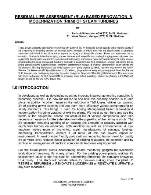
1.0 INTRODUCTION<br />
In developed as well as developing countries increase in power generating capacities is<br />
becoming essential. It is now for utilities to see how this capacity addition is to take<br />
place. In addition to other measures like reduction in T&D losses, utilities can prolong<br />
<strong>life</strong> of existing power stations and use them more efficiently without compromising on<br />
safety standards. This brings in need for Ageing Management <strong>based</strong> <strong>renovation</strong> &<br />
modernization including uprating of existing plants. We must go out there and see the<br />
health of the equipment, assess the <strong>residual</strong> <strong>life</strong> of various components, and take<br />
necessary measures for <strong>life</strong> extension including uprating of the unit as a whole. The<br />
<strong>life</strong> extension including uprating of an existing unit amounts to capacity addition with<br />
much less burden on resources, both monitory as well as environmental. A new<br />
machine implies more of everything, steel, manufacturing of castings, forgings,<br />
machining, transportation, cement & lot more. All this has severe impact on<br />
environment. An environment friendly policy without impacting human need for quality<br />
<strong>life</strong> at micro level, requires better utilization of existing resources, <strong>life</strong> extension and by<br />
implication management of cracks in components becomes very important.<br />
For the future power plants incorporating health monitoring gadgets for systematic<br />
evaluation of remaining <strong>life</strong> is very simple. For the existing power plants, <strong>residual</strong> <strong>life</strong><br />
<strong>assessment</strong> study is the first step for determining remaining <strong>life</strong> popularly known as<br />
RLA Study. This study will provide details for decision making about the plant TO<br />
RETIRE or REFURBISH or RENOVATE & MODERNISE or RENOVATE & UPRATE or<br />
any such measures.<br />
International Conference & Exhibition<br />
<strong>India</strong> Thermal Power-4<br />
Page 1 of 22
2.0 STEPS OF RESIDUAL LIFE ASSESSMENT<br />
2.1 COLLECTION OF BACK GROUND INFORMATION<br />
Plant data management plays a crucial role and involves the collection, storage, and<br />
manipulation of data associated with operating and maintenance histories, inspection,<br />
failure analysis, <strong>life</strong> <strong>assessment</strong>, resources, schedules etc. Data management<br />
systems often contain plant generic as well as plant specific data which can be used to<br />
identify key influences and root causes of existing or future threats to plant availability<br />
or performance.<br />
2.1.1 Material Data<br />
Following information are required to be collected regarding the set whose <strong>life</strong> is to<br />
be estimated:<br />
<br />
<br />
<br />
The drawings of critical components viz. rotors, casings, valves & valve chests,<br />
guide blade carriers, steam inlet & exhaust connections etc.<br />
Materials of various critical components as mentioned above & their test<br />
certificates including NDT results like defectograms etc.<br />
Thermodynamic cycle and strength design data. Stress distribution in various<br />
critical components as envisaged during design stage.<br />
2.1.2 Operational History<br />
It is very important to know how the set has been operated in the past at the power<br />
station.<br />
The effectiveness of the calculations made depends upon the accuracy of this data.<br />
The observations during planned shut downs provide lot of information on<br />
equipment's condition. Generally, the Maintenance Planning Division of the power<br />
plant utilises this information for preventive maintenance and replacements. History<br />
cards covering the replacements done during routine maintenance / forced outages<br />
and planned overhauls are reviewed so that present status of the equipment is<br />
assessed and equipment degradation trend is formulated.<br />
2.2 PRELIMINARY RESIDUAL LIFE ASSESSMENT CALCULATIONS TO IDENTIFY<br />
CRITICAL ZONES<br />
Based on design data the critical components / zones which need special attention<br />
with regard to normal wear, erosion, cracks, material properties etc. are identified.<br />
The background information & operational history facilitate preliminary <strong>residual</strong> <strong>life</strong><br />
<strong>assessment</strong> studies / calculation.<br />
Condition-<strong>based</strong> techniques are used to refine the accuracy of calculation-<strong>based</strong><br />
methods and are essential to expose any defect or unforeseen damage derived<br />
from initial fabrication or unrecorded operational upsets.<br />
International Conference & Exhibition<br />
<strong>India</strong> Thermal Power-4<br />
Page 2 of 22
The components & zones identified as above are rigorously inspected after opening<br />
of the turbine / assemblies & checks mentioned in following clauses shall be carried<br />
out:<br />
2.3 COMPONENT INTEGRITY ASSESSMENT<br />
All the rotating and stationary components are cleaned by abrasive jet using<br />
Alumina powder or sand. This is done to remove all products of oxidation from the<br />
surfaces to facilitate proper interpretation of the subsequent tests. Various<br />
components of steam turbine are subjected to the following tests:<br />
2.3.1 Visual Examination<br />
Visual examination is carried out very minutely to ascertain damages such as<br />
breakage, cracks, corrosion, pitting, wear etc. Wherever necessary, optical aids<br />
e.g. mirror, magnifying glass etc. is used.<br />
2.3.2 Dye Penetration Test (DPT)<br />
This technique is adopted primarily for detection of cracks or crack like<br />
discontinuities that are open to the surface of the component. The area to be<br />
examined is cleaned and then the penetrant is applied over the surface. After<br />
removing the excess penetrant, the developer is applied which by blotting action<br />
helps to draw the penetrant from defect and spread it over the surface.<br />
2.3.3 Magnetic Particle Inspection (MPI)<br />
This technique is adopted for locating surface or sub surface discontinuities like<br />
seams, laps, quenching cracks etc. This method is also used for detecting surface<br />
fatigue cracks developed during service.<br />
Wet fluorescent continuous method is used for examining accessible surface area<br />
of the components. Magnetisation is done using coiling and / or Electro magnetic<br />
yoke. Adequacy of the field strength is verified by using field strength indicator.<br />
Water or kerosene <strong>based</strong> fluorescent particles are sprayed on the magnetised area<br />
by means of the spray bottles, while magnetising field is still on. The magnetised<br />
and sprayed areas are examined under hand held ultra violet light for the presence<br />
of defect indications. All components like casings, surfaces of rotor discs etc. are<br />
examined by this method.<br />
All cylindrical surfaces including blades are examined by the coiling method. This<br />
method is only suitable for ferromagnetic materials.<br />
International Conference & Exhibition<br />
<strong>India</strong> Thermal Power-4<br />
Page 3 of 22
2.3.4 Ultrasonic Testing (UT)<br />
By using ultrasonic sound waves, the sub-surface flaws and non-metallic inclusions<br />
can be detected. Size and configuration are also determined and recorded. The<br />
testing is carried out using suitable techniques and probes depending on the<br />
component geometry and its location. Wire brushing and light grinding are<br />
employed to mend local irregularities and undulations on the surface, if any.<br />
Machine oil mixed with grease is used as couplent. All accessible critical areas are<br />
examined ultrasonically using normal and angle probes. These include steam<br />
chests, casings, rotors, welds in stationary components etc. The surfaces thus<br />
prepared, are first checked with 2-4 MHz normal probes followed by 45° angle<br />
probes. The circumferential welds are checked with 45/60° angle probes.<br />
2.3.5 Hardness Test<br />
Hardness can be used as an indicator for the state of the steel in its <strong>life</strong> cycle.<br />
Hardness measurements provide a useful indication of the extent of microstructural<br />
degradation due to thermal exposure and creep damage in components operating<br />
at high temperatures and pressures. In-situ hardness testing is performed at<br />
suitable locations, using portable hardness tester. All critical areas, especially the<br />
high temperature zones of rotor, heat affected areas of welds in stationary parts are<br />
tested for their hardness.<br />
2.3.6 In-situ Metallographic Examination by Replication Technique<br />
Replication is the technique adopted to obtain microstructure in-situ by nondestructive<br />
metallography. In this technique, each of the spots chosen for<br />
examination is finely polished using portable metallographic surface preparation<br />
equipment, etched by suitable chemical agent, examined by microscope and the<br />
reverse image of the metal surface is taken on to a plastic replicating film for<br />
detailed laboratory examination. The replica of the microstructure is examined at<br />
site for its quality by portable optical microscope.<br />
All the critical areas of the rotors and the stationary components with special<br />
attention to the high temperature zone and welds are metallographically examined<br />
and their replica taken. If any defect has been observed by non-destructive testing<br />
at any zone, then such zones are given extra attention. The replicas are first<br />
examined in the laboratory under light microscope for gross metallurgical structure<br />
and then, if necessary, under the Scanning electron microscope for detection of<br />
creep damage, if any.<br />
2.4 TESTS PERFORMED ON CRITICAL TURBINE COMPONENTS<br />
2.4.1 Turbine Rotors<br />
International Conference & Exhibition<br />
<strong>India</strong> Thermal Power-4<br />
Page 4 of 22
After thorough cleaning of the rotor surface and blading, following examinations are<br />
carried out :<br />
Visual examination of the rotor surface, moving blades and shrouds for any<br />
abnormality.<br />
Boroscopic examination of rotor bore<br />
Magnetic particle examination and/or dye penetration test of the rotor with<br />
special emphasis on the inlet zone, blades and shrouds.<br />
Ultrasonic test of accessible areas of the rotor for internal defects to ascertain<br />
major flaws and how far they have grown from initial stage of manufacture.<br />
Special attention is given to inlet zone of the rotor.<br />
Hardness and Microstructure testings at steam entry and exit sides<br />
Natural Frequency Measurement of free standing blades of LP Rotor.<br />
2.4.2 Stationary Components<br />
All stationary components viz. turbine casings & guide blades, high temperature inlet<br />
& exhaust connections, stop & control valves, strainer housings, U, I, & L- seal rings,<br />
gland seal bodies etc. are cleaned thoroughly and following examinations are<br />
carried out :<br />
<br />
<br />
<br />
<br />
Visual examination of the component with special emphasis to the transition<br />
zones and welded areas for crack, corrosion, erosion or any other defect.<br />
Magnetic particle inspection and/or dye penetration test to detect surface and<br />
sub-surface cracks.<br />
Ultrasonic examination for internal defects.<br />
In-situ microstructure examination and hardness test.<br />
2.4.3 High temperature fasteners<br />
All the fasteners of high temperature zone will be checked for detection of cracks<br />
by MPI / DPT / UT.<br />
Sample survey of turbine inner casing joint plane fasteners of high temperature<br />
zone is carried out by destructive test on sample studs to determine mechanical<br />
properties and impact values. Microstructure examination is also carried out.<br />
2.4.4 Turbine Bearings<br />
All turbine bearings are checked visually for any damage, by DP test for cracks, and<br />
by UT for babbit bondage.<br />
3.0 FINAL RESIDUAL LIFE ASSESSMENT<br />
Based on the material defect data generated (as mentioned at para 2.4 above) and<br />
the operational data obtained from site, stress analysis and <strong>life</strong> estimation<br />
calculations are performed.<br />
Operational data along with material properties and design parameters are used for<br />
<strong>residual</strong> <strong>life</strong> calculation. This <strong>residual</strong> <strong>life</strong> evaluation provides important information<br />
on components’ <strong>life</strong> consumed and further use-worthiness or otherwise of the<br />
International Conference & Exhibition<br />
<strong>India</strong> Thermal Power-4<br />
Page 5 of 22
component. Based on above evaluation and material testing, decision regarding<br />
rectification / replacement is taken.<br />
In all these calculations the reliability and accuracy of the operating data is of vital<br />
importance. Any prediction of remaining <strong>life</strong> may prove to be inaccurate if data is<br />
incomplete or inaccurate.<br />
Based on these studies, for extending <strong>life</strong> of steam turbine components ,<br />
recommendations are given regarding:<br />
Remaining <strong>life</strong> of steam turbine components.<br />
Immediate replacement of a component is required or it can be replaced after a<br />
prescribed period.<br />
Repair of a particular component<br />
Change in steam parameters at the inlet, if required.<br />
De-rating of steam turbine.<br />
Alterations in the mode of future operation of the set.<br />
Alterations in the material of certain components<br />
Need for more often inspections.<br />
Proposals for R & M.<br />
4.0 R & M OF STEAM TURBINES :<br />
Reliable and economical power generation is the primary goal of each electrical<br />
utility worldwide. Such a goal can be achieved through:<br />
<br />
<br />
<br />
Maximizing the efficiency of the turbine-generator.<br />
Extending the intervals between inspections and<br />
Achieving greater reliability in operation.<br />
During the development and design of its steam turbines, BHEL considers all of<br />
these factors in order to offer attractive products to its customers. This is achieved<br />
by the following:<br />
<br />
<br />
<br />
Improving the efficiency of the turbine with use of advanced blading.<br />
Maximizing the use of existing hardware whenever practical.<br />
Extending the service intervals by use of advanced manufacturing techniques as<br />
well as carefully selected materials for the components. This also leads towards<br />
greater reliability in plant operation.<br />
IMPROVEMENT IN PERFORMANCE & OUTPUT OF STEAM TURBINE CAN BE<br />
ACHIEVED BY FOLLOWING:<br />
<br />
<br />
<br />
<br />
Use of improved blade profile which result into reduction in the aerodynamic<br />
flow losses e.g. profile loss, secondary flow loss & tip leakage loss.<br />
More uniform flow distribution.<br />
Optimization of flowpath.<br />
Improvement in shaft sealing system.<br />
International Conference & Exhibition<br />
<strong>India</strong> Thermal Power-4<br />
Page 6 of 22
Reduction in pressure drops.<br />
Reduced friction losses.<br />
Optimization of inlet & exhaust section geometry of valves & casings.<br />
Optimization of exhaust loss.<br />
5.0 BHEL’S PROPOSAL FOR R&M OF 200 / 210 MW STEAM<br />
TURBINES (LMW DESIGN):<br />
BHEL, Haridwar, has manufactured and supplied 57 sets of Type K-210-130 (LMW<br />
Design) steam turbines. About 10 sets of similar design, imported directly by<br />
Utilities, from Russia, are also under operation. These sets have already completed<br />
13 to 30 years of operation. Thus the useful <strong>life</strong> of most of the sets is already over.<br />
The Steam Turbine of Type K-210-130 (LMW Design) was designed in early 60’s,<br />
therefore, there is good scope for <strong>renovation</strong> & modernization of these sets to<br />
extend their operating <strong>life</strong>, making them efficient and increasing their output. The<br />
upgradation of HP and LP Turbines is possible by incorporating features mentioned<br />
al S.No. 2.0 above.<br />
EXISTING DESIGN:<br />
Existing 210 MW Steam Turbine (LMW design ) is fitted with impulse blading.<br />
Figure 1 shows its cross section of HP Turbine & Figure 3 shows the cross section<br />
of LP Turbine. In this design steam pressure drop takes place mainly in guide<br />
blades provided in the diaphragms, while passing through moving blades there is<br />
negligible pressure drop.<br />
The LP Turbine is double flow and is provided with 2X4 stages. It has impulse<br />
blading. The maximum heat drop takes place across the fixed / guide blades. The<br />
fixed / guide blades are called DIAPHRAGMS which are in two halves. 1 st & 2 nd<br />
stage diaphragms are fitted in liners, which in turn are fitted in the casing. The<br />
penultimate stage of this LPT is BAUMEN STAGE which is provided to direct part of<br />
the steam flow to the condenser so as to reduce the moisture content as well as the<br />
volume of the steam flow in the last stages.<br />
The LP Rotor has a shaft and the discs of all the stages are shrink fitted on it. The<br />
blades are fitted in the grooves provided in the discs. These blades are provided<br />
with damping wire for dampening the vibrations.<br />
5.1 IMPROVEMENT IN HP TURBINE:<br />
The HP turbines of 200 / 210 MW having impulse blading can be retrofitted by<br />
BHEL with state of art high efficiency reaction blading. In this design steam pressure<br />
drop takes place in guide blades as well as moving blades. Outer casing is kept<br />
same, if found healthy in RLA study. The internals i.e. Rotor, Liners and diaphragms<br />
are to be replaced with Monoblock HP Rotor and Guide Blade Carriers having more<br />
efficient reaction blading (Tx profile).<br />
International Conference & Exhibition<br />
<strong>India</strong> Thermal Power-4<br />
Page 7 of 22
ADVANTAGES<br />
It gives following advantages over existing turbine:<br />
<br />
<br />
<br />
<br />
<br />
Reduction in specific heat consumption.<br />
Increased power output<br />
Renewed blade <strong>life</strong>time.<br />
Separate Diaphragms are eliminated.<br />
Servicing time will be reduced as no centering of diaphragms will be needed<br />
which is otherwise time consuming.<br />
International Conference & Exhibition<br />
<strong>India</strong> Thermal Power-4<br />
Page 8 of 22
HP<br />
CASING<br />
LINER<br />
ROTOR<br />
<br />
Fig. 1 : Existing HP Turbine with Impulse Blading<br />
HP CASING<br />
GUIDE BLADE<br />
CARRIERS<br />
ROTOR<br />
Fig. 2 : HP Turbine retrofitted with Reaction Blading<br />
International Conference & Exhibition<br />
<strong>India</strong> Thermal Power-4<br />
Page 9 of 22
ADVANTAGES<br />
It gives following advantages over existing turbine:<br />
<br />
<br />
<br />
<br />
<br />
Reduction in specific heat consumption.<br />
Increased power output<br />
Renewed blade <strong>life</strong>time.<br />
Separate Diaphragms are eliminated.<br />
Servicing time will be reduced as no centering of diaphragms will be needed<br />
which is otherwise time consuming.<br />
5.2 IMPROVEMENT IN LP TURBINE:<br />
Monoblock LP Rotor with advanced blading is provided for retrofit and existing liners<br />
& diaphragms are to be replaced by new liners & guide blade carriers. LP Rotor<br />
blades as well as guide blades are state of art high efficiency blading. The LPT will<br />
have 2X4 stages. The 1st stage of moving & guide blades will be having “Tx”<br />
blading. The 2nd stage of moving blades will be “F” blading. The moving blades of<br />
3rd & 4th stages will be “TAPER & TWISTED FREE STANDING BLADES”. The<br />
guide blades of 2nd and 3rd stages will be “TAPER & TWISTED PRECISION CAST<br />
BLADES”. The guide blades of 4th stage will be “BANANA TYPE” hollow guide<br />
blades.<br />
LPT EXHAUSTHOOD:<br />
Existing LP Exhaust hood of LP Casing shall be reused and modified at site as part<br />
of upgradation. In the Exhaust hood portion some sheet metal will be cut off &<br />
modified to improve the steam flow and some additional stiffening arrangements will<br />
be provided.<br />
International Conference & Exhibition<br />
<strong>India</strong> Thermal Power-4<br />
Page 10 of 22
FIG.3-A: DETAILS OF EXISTING DESIGN FLOWPATH<br />
<br />
FIG. 3-B: DETAILS OF MODIFIED FLOWPATH<br />
International Conference & Exhibition<br />
<strong>India</strong> Thermal Power-4<br />
Page 11 of 22
Fig. 4 : LP CASING: EXISTING DESIGN<br />
<br />
<br />
<br />
Fig. 5 : LP CASING: AFTER MODIFICATION<br />
5.3 UPRATED CONDITION (UNDER NORMAL CYCLE OPERATION):<br />
The steam turbine after uprating shall be able to generate power as per following<br />
parameters:<br />
Reference original HBD TCD-210-33-2 Regime no. 1<br />
Main Steam Flow : 662 T/Hr<br />
International Conference & Exhibition<br />
<strong>India</strong> Thermal Power-4<br />
Page 12 of 22
Main Steam / HRH Steam Temperature: 535/535ºC<br />
Main Steam Pressure: 130 ata<br />
Back Pressure: …0.1042 ata<br />
5.3.1 EXPECTED PRESENT PERFORMANCE LEVEL:<br />
Considering deterioration due to aging as per ASME-PTC-6 Report 1985, following<br />
will be the performance levels:<br />
PRESENT power output with steam flow of 662 t/h & rated parameters : 202.4 MW<br />
EXPECTED PERFORMANCE IMPROVEMENT IN THE EXISTING IMPULSE DESIGN SET AFTER<br />
REFURBISHMENT OF HP& LP TURBINES AT RATED PAPARMETERS, 0% MU& 33 DEGREE<br />
COOLING WATER TEMPERATURE:<br />
BRAND<br />
NEW ST<br />
DETERIORATED<br />
CONDITION<br />
UPGRADED<br />
ST<br />
UPGRADED ST WITH<br />
ENHANCED STEAM<br />
FLOW<br />
MAIN<br />
STEAM<br />
FLOW T/Hr<br />
LOAD<br />
(MW)<br />
662 662 662 695<br />
210 202.4 217.5 225<br />
(This is only indicative data and will subject to change for specific project)<br />
5.3.2 TIME REQUIRED FOR IMPLEMENTATION OF THE MODIFICATION:<br />
This modification is expected to be implemented at site during extended CAPITAL<br />
OVERHAUL.<br />
5.4 WORK INVOLVED IN RETROFFITING:<br />
<br />
<br />
Residual Life Assessment (RLA) study of steam turbine components.<br />
Overhauling / Replacement of internals of IP Turbine and correction in steam<br />
flowpath.<br />
5.4.1 FOR HP TURBINE:<br />
<br />
<br />
<br />
<br />
<br />
<br />
Removal of existing HP Rotor, Liners, Diaphragms, nozzle segments and shaft<br />
seals.<br />
Removal of H.P.Casing from its position after cutting the pipelines connected<br />
with the casing. The pipelines must be suitably locked before taking up the<br />
cutting job.<br />
Installation of the NEW H.P.Casing in its position & welding of relevant pipe<br />
connections.<br />
Installation of new HP rotor, Guide Blade carriers having reaction blading and<br />
shaft seals.<br />
Nozzle segment rings of first stage are also proposed to be replaced by new<br />
ones (of existing design) to enhance the efficiency.<br />
Usage of new set of parting plane fasteners of HP Cylinder.<br />
International Conference & Exhibition<br />
<strong>India</strong> Thermal Power-4<br />
Page 13 of 22
5.4.2 FOR LP TURBINE:<br />
<br />
<br />
<br />
<br />
<br />
<br />
<br />
<br />
<br />
Removal of existing Liners, Diaphragms & Rotor.<br />
Measurement of log dimensions (as per log sheet to be supplied by BHEL,<br />
Hardwar), during previous overhaul.<br />
Cutting of deflectors / ribs & blanking the space in LP casing due to removal of<br />
baumen stage.<br />
Modification of structure at the exhaust end of LPC to facilitate installation of liner<br />
& guide blade carrier.<br />
Installation of water spray system in position.<br />
Matching / machining of parting plane and correction, if any.<br />
Installation of Liners & Guide Blade Carriers in position.<br />
Installation of new Mono-block LP Rotor in position.<br />
Measurement of Steam Flowpath and correction, if any.<br />
5.5 PAY BACK PERIOD:<br />
Pay back period will be approximately 3 years.<br />
International Conference & Exhibition<br />
<strong>India</strong> Thermal Power-4<br />
Page 14 of 22
6.0 BHEL’S PROPOSAL FOR R&M OF 200 / 210 MW STEAM<br />
TURBINES (KWU DESIGN):<br />
EXISTING DESIGN:<br />
<br />
<br />
<br />
Existing 210 MW Steam Turbine (SIEMENS-KWU design ) is fitted with T2<br />
reaction blading. Figure 6 shows its cross section of HP Turbine, IP & LP<br />
turbines. The LP Turbine is double flow and is provided with 2X8 stages. It also<br />
has T2 reaction blading.<br />
For HP Inlet assembly, HP Outer casing has buttress threads of 580x9 and<br />
accordingly Breech nuts are provided with matching buttress threads.(Fig.7)<br />
The HP Exhaust elbows are provided with Serrated Packing.<br />
6.1 DESIGN CRITERIA<br />
The purpose of the proposal for modernization of HP & IP Turbines (Siemens-KWU<br />
Design), is to provide a cost effective modifications & upgradation package, to<br />
maximize the improvements on HP & IP Turbines’ performance.<br />
After <strong>renovation</strong> & modernization of HP & IP Turbines, by implementation of the<br />
proposal, including action taken in accordance to recommendations of RLA Study,<br />
by way of rectification / replacements of steam turbine components which are being<br />
retained, their service <strong>life</strong> is expected to be about 30 years. The interval between<br />
inspections of inner parts of HP & IP Turbine is 6 years.<br />
International Conference & Exhibition<br />
<strong>India</strong> Thermal Power-4<br />
Page 15 of 22
FIGURE 6<br />
International Conference & Exhibition<br />
<strong>India</strong> Thermal Power-4<br />
Page 16 of 22
CYL PIN<br />
BREECH<br />
NUT<br />
OUTER<br />
CASING<br />
GUIDE<br />
BLADE<br />
CARRIER<br />
U-RING<br />
INLET<br />
INSERT<br />
HPT INLET ASSEMBLY<br />
DESCRIPTION BUTTRESS THREDS SIZE<br />
OLD DESIGN<br />
NEW DESIGN<br />
HP OUTER CASING 580X9 580X20<br />
BREECH NUTS 580X9 580X20<br />
Fig. 7 : HP INLET ASSEMBLY EXISTING DESIGN<br />
International Conference & Exhibition<br />
<strong>India</strong> Thermal Power-4<br />
Page 17 of 22
6.2 IMPROVEMENT IN HP & IP TURBINE:<br />
The HP & IP turbines of 210 MW, having T2 profile blading, can be retrofitted by<br />
BHEL with state of art high efficiency T4 profile reaction blading. The existing HP<br />
Inlet Assembly will be replaced by new design well proven HP Inlet Assembly for<br />
ease in its assembly & dismantling (Refer Fig.7). The existing HP Exhaust elbows<br />
having Serrated Gaskets will be replaced by well proven new design HP Exhaust<br />
Elbows having U-Ring for enhancing reliability (Refer Fig.8). This will require<br />
following components:<br />
SCOPE OF SUPPLY FOR HPT<br />
SCOPE OF SUPPLY FOR IPT<br />
COMPLETE ASSEMBLED MODULE<br />
OF HPT FITTED WITH HP ROTOR &<br />
HP INNER CASING WITH T4 / T4X<br />
PROFILE BLADING (WITH STEAM<br />
FLOWPATH SO THAT INCREASED<br />
QUQNTITY OF STEAM MAY PASS)<br />
ALONGWITH HP INLET ASSEMBLY<br />
AND HPT EXHAUST ELBOWS.<br />
IP INNER CASING BLADED WITH T4<br />
PROFILE BLADES, FULLY BLADED IP<br />
ROTOR WITH T4 PROFILE BLADES, IP<br />
SHAFT SEALS, A SET OF HPR-IPR &<br />
IPR-LPR COUPLING BOLTS ALONG<br />
WITH NECESSRY KEYS ETC.<br />
6.3 RECOMMENDED CHANGES IN LPR FOR LIFE EXTENSION:<br />
It is recommended to replace last two stages of free standing blades i.e. stage no.<br />
2L, 3L, 2R & 3-R, as the set has already completed more than 1,60,000 hours of<br />
operation, by new ones, and NFT be performed for improving reliability during<br />
operation. This will require following material<br />
SCOPE OF SUPPLY FOR LPT<br />
COMPLETE SET OF MOVING BLADING MATERIAL OF 2L, 2R, 3L & 3R OF LP<br />
ROTOR ALONGWITH CLAMPING PIECES.<br />
International Conference & Exhibition<br />
<strong>India</strong> Thermal Power-4<br />
Page 18 of 22
6.4 THERMAL INSULATION:<br />
Mineral wool spray thermal insulation will be supplied for Steam Turbine.<br />
6.5 WORK REQUIRED TO BE DONE:<br />
S.No.<br />
1.0-<br />
1.1-<br />
1.3-<br />
1.4-<br />
1.5-<br />
1.6-<br />
2.0-<br />
2.1-<br />
2.2-<br />
2.3-<br />
IN HPT<br />
REMOVAL OF OLD HPT MODULE FROM ITS POSITION AFTER<br />
DISMANTLING THE HP INLET ASSEMBLY AND HPT EXHAUST<br />
ELBOWS.<br />
THE OLD HP INLET ASSEMBLY (INLET INSERTS WITH<br />
BREECH NUTS) AND HPT EXHAUST ELBOWS ARE TO BE CUT<br />
FROM MAIN STEAM PIPES AND CRH STEAM PIPES<br />
RESPECTIVELY.<br />
NEW IMPROVISED HPT MODULE IS TO BE PLACED IN<br />
POSITION, ALIGNED & CENTERED WITH OTHER TURBINE<br />
MODULES / ELEMENTS.<br />
HP INLET ASSEMBLY OF NEW MODULE IS TO BE WELDED<br />
WITH MAIN STEAM PIPES.<br />
HPT EXHAUST ELBOWS ARE TO BE WELDED WITH CRH<br />
STEAM PIPES.<br />
THE ASSEMBLY OF “HP INLET ASSEMBLY” AND HPT<br />
EXHAUST ELBOWS WITH HPT IS TO BE COMPLETED.<br />
IN IPT<br />
REMOVAL OF OLD IP ROTOR & IP INNER CASING.<br />
INSTALLATION OF NEW IP INNER CASING WITH T4 PROFILE<br />
BLADING, ITS CENTERING & ALIGNMENT.<br />
INSTALLATION OF NEW IP ROTOR WITH T4 PROFILE<br />
BLADING, ALIGMENT & CENTERING.<br />
COMPLETION OF BOX UP OF IPT.<br />
IN LPT<br />
3.0-<br />
3.1-<br />
3.2-<br />
3.3-<br />
3.4-<br />
• REMOVAL OF EXISTING OLD BLADING OF STAGES 2L, 2R, 3L<br />
& 3R.<br />
• CLEANING OF GROOVES OF BLADES PROVIDED IN LP<br />
ROTOR AND CRACK DETECTION BY MPI.<br />
• ASSEMBLY OF NEW BLADES OF ABOVE MENTIONED<br />
STAGES IN POSTION.<br />
• ENSURING PROPER ASSEMBLY OF BLADES BY NATURAL<br />
FREQUESNCY TESTING (NFT).<br />
• BALANCING OF LP ROTOR AT 3000 RPM.<br />
International Conference & Exhibition<br />
<strong>India</strong> Thermal Power-4<br />
Page 19 of 22
III<br />
DETAIL-II<br />
U-RING<br />
HPT EXHAUST ELBOW<br />
FIGURE- 8<br />
International Conference & Exhibition<br />
<strong>India</strong> Thermal Power-4<br />
Page 20 of 22
6.6 RLA BASED REPAIR / REPLACEMENTS OF THE COMPONENTS / ASSEMBLIES<br />
The major assemblies / components, such as given below, shall be subjected to<br />
RLA Study:<br />
<br />
<br />
<br />
<br />
<br />
<br />
<br />
IP Outer Casing<br />
LPT Inner-Inner Casing, Guide Blades, guide Blade carriers, Gland Seal<br />
Housings.<br />
Cross Around Pipes (CAP)<br />
ESV & Control Valve Steam chests of HPT as well as their Internals.<br />
IV & Control Valve Steam chests of IPT as well as their Internals.<br />
Main Steam (MS) / Hot Reheat (HRH) Steam Strainer Housings & their Strainer<br />
elements.<br />
Turbine Bearings<br />
6.7 ADVANTAGES:<br />
It gives following advantages over existing turbine:<br />
<br />
<br />
<br />
<br />
<br />
<br />
Reduction in specific heat consumption.<br />
Increased power output<br />
Renewed blade <strong>life</strong>time.<br />
Life extension of steam turbine.<br />
For ease of assembly & dismantling of HP Inlet assembly, the buttress threads of<br />
580x20 have been provided on HP Outer Casing & Breech nuts in place of<br />
existing buttress threads of 580X9.<br />
The HPT Exhaust Elbows assembly has been provided with U-Ring in each<br />
exhaust connection in place of Serrated Gasket provided earlier thus increasing<br />
reliability of the assembly.<br />
International Conference & Exhibition<br />
<strong>India</strong> Thermal Power-4<br />
Page 21 of 22
6.8 Expected Performance Improvement in the existing impulse design set after<br />
Refurbishment of HP & IP Turbines & replacement of Blades Of 2L, 2R, 3L & 3R<br />
Blades Of LP Rotor:<br />
(A) FOR TMCR CONDITION<br />
AS PER HBD<br />
AS PER EXISTING<br />
CONDITION (for specific<br />
project)<br />
AFTER R&M( for<br />
specific project)<br />
LOAD (VWO) IN MW 210 197 216.5<br />
STEAM FLOW (T/Hr) 630 662 650<br />
MS PR (ata) 150 142 150<br />
MS TEMP DEGREE C 535 538 535<br />
HRH STEAM TEMP<br />
535 535 535<br />
DEGREE C<br />
VACUUM (ata) 0.1033 0.15 0.105<br />
(B) FOR VWO CONDITION:<br />
(This is only indicative data and will subject to change for specific project)<br />
AS PER HBD AS PER EXISTING AFTER R&M<br />
CONDITION<br />
LOAD (VWO) IN MW 221 197 228<br />
STEAM FLOW (T/Hr) 662 662 686.3<br />
MS PR (ata) 150 142 150<br />
MS TEMP DEGREE C 535 538 535<br />
HRH STEAM TEMP<br />
535 535 535<br />
DEGREE C<br />
VACUUM (ata) 0.1033 0.150 0.106<br />
7.0 CONCLUSION<br />
(This is only indicative data and will subject to change for specific project)<br />
Remaining Life Assessment <strong>based</strong> R&M and UPRATING of the units of Thermal<br />
Power Station is most cost effective way of augmenting generation capacity and <strong>life</strong><br />
extension. BHEL have acquired a vast experience of conducting RLA studies and<br />
handling variety of defects in the components. BHEL being designer of power plant<br />
equipment naturally have an advantage in dealing with unforeseen situations<br />
encountered during implementation of R&M including UPRATING proposals. It is<br />
advisable that utilities take initiative to have their machines studied thoroughly for<br />
their remaining <strong>life</strong> before implementing R&M proposals for improvement in Output,<br />
reliability & efficiency. While choosing the agency for conducting such studies<br />
BHEL’s inherent advantage and vast experience should be given due<br />
consideration.<br />
xxxxxxxxxxxx<br />
International Conference & Exhibition<br />
<strong>India</strong> Thermal Power-4<br />
Page 22 of 22