K109g Pressure Relief Valves - Hansen Technologies
K109g Pressure Relief Valves - Hansen Technologies
K109g Pressure Relief Valves - Hansen Technologies

You also want an ePaper? Increase the reach of your titles
YUMPU automatically turns print PDFs into web optimized ePapers that Google loves.
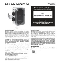
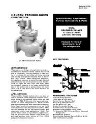
Bulletin <strong>K109g</strong><br />
SEPT 2012<br />
Specifications, Applications,<br />
Service Instructions & Parts<br />
REFRIGERANT<br />
PRESSURE RELIEF<br />
VALVE<br />
For Ammonia and<br />
Halocarbon Gas Service<br />
Safety <strong>Relief</strong> to Atmosphere<br />
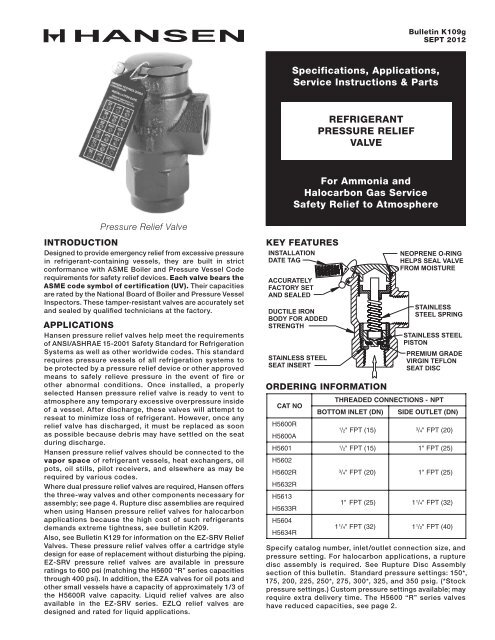
<strong>Pressure</strong> <strong>Relief</strong> Valve<br />
INTRODUCTION<br />
Designed to provide emergency relief from excessive pressure<br />
in refrigerant-containing vessels, they are built in strict<br />
conformance with ASME Boiler and <strong>Pressure</strong> Vessel Code<br />
requirements for safety relief devices. Each valve bears the<br />
ASME code symbol of certification (UV). Their capacities<br />
are rated by the National Board of Boiler and <strong>Pressure</strong> Vessel<br />
Inspectors. These tamper-resistant valves are accurately set<br />
and sealed by qualified technicians at the factory.<br />
APPLICATIONS<br />
<strong>Hansen</strong> pressure relief valves help meet the requirements<br />
of ANSI/ASHRAE 15-2001 Safety Standard for Refrigeration<br />
Systems as well as other worldwide codes. This standard<br />
requires pressure vessels of all refrigeration systems to<br />
be protected by a pressure relief device or other approved<br />
means to safely relieve pressure in the event of fire or<br />
other abnormal conditions. Once installed, a properly<br />
selected <strong>Hansen</strong> pressure relief valve is ready to vent to<br />
atmosphere any temporary excessive overpressure inside<br />
of a vessel. After discharge, these valves will attempt to<br />
reseat to minimize loss of refrigerant. However, once any<br />
relief valve has discharged, it must be replaced as soon<br />
as possible because debris may have settled on the seat<br />
during discharge.<br />
<strong>Hansen</strong> pressure relief valves should be connected to the<br />
vapor space of refrigerant vessels, heat exchangers, oil<br />
pots, oil stills, pilot receivers, and elsewhere as may be<br />
required by various codes.<br />
Where dual pressure relief valves are required, <strong>Hansen</strong> offers<br />
the three-way valves and other components necessary for<br />
assembly; see page 4. Rupture disc assemblies are required<br />
when using <strong>Hansen</strong> pressure relief valves for halocarbon<br />
applications because the high cost of such refrigerants<br />
demands extreme tightness, see bulletin K209.<br />
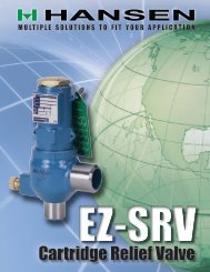
Also, see Bulletin K129 for information on the EZ-SRV <strong>Relief</strong><br />
<strong>Valves</strong>. These pressure relief valves offer a cartridge style<br />
design for ease of replacement without disturbing the piping.<br />
EZ-SRV pressure relief valves are available in pressure<br />
ratings to 600 psi (matching the H5600 “R” series capacities<br />
through 400 psi). In addition, the EZA valves for oil pots and<br />
other small vessels have a capacity of approximately 1/3 of<br />
the H5600R valve capacity. Liquid relief valves are also<br />
available in the EZ-SRV series. EZLQ relief valves are<br />
designed and rated for liquid applications.<br />
KEY FEATURES<br />
INSTALLATION<br />
DATE TAG<br />
ACCURATELY<br />
FACTORY SET<br />
AND SEALED<br />
DUCTILE IRON<br />
BODY FOR ADDED<br />
STRENGTH<br />
STAINLESS STEEL<br />
SEAT INSERT<br />
ORDERING INFORMATION<br />
CAT NO<br />
H5600R<br />
H5600A<br />
NEOPRENE O-RING<br />
HELPS SEAL VALVE<br />
FROM MOISTURE<br />
STAINLESS<br />
STEEL SPRING<br />
STAINLESS STEEL<br />
PISTON<br />
PREMIUM GRADE<br />
VIRGIN TEFLON<br />
SEAT DISC<br />
THREADED CONNECTIONS - NPT<br />
BOTTOM INLET (DN)<br />
SIDE OUTLET (DN)<br />
1<br />
/2" FPT (15)<br />
3<br />
/4"<br />
FPT (20)<br />
H5601<br />
1<br />
/2" FPT (15)<br />
1" FPT (25)<br />
H5602<br />
H5602R<br />
H5632R<br />
H5613<br />
H5633R<br />
H5604<br />
H5634R<br />
3<br />
/4" FPT (20)<br />
1" FPT (25)<br />
1" FPT (25)<br />
1 1 /4"<br />
FPT (32)<br />
1 1 /4"<br />
FPT (32)<br />
1 1 /2"<br />
FPT (40)<br />
Specify catalog number, inlet/outlet connection size, and<br />
pressure setting. For halocarbon applications, a rupture<br />
disc assembly is required. See Rupture Disc Assembly<br />
section of this bulletin. Standard pressure settings: 150*,<br />
175, 200, 225, 250*, 275, 300*, 325, and 350 psig. (*Stock<br />
pressure settings.) Custom pressure settings available; may<br />
require extra delivery time. The H5600 “R” series valves<br />
have reduced capacities, see page 2.
VALVE SIZING AND SELECTION<br />
Step 1: Use the formula below, per ANSI/ASHRAE 15-2001<br />
Safety Standard for Refrigeration Systems to calculate the<br />
minimum required discharge capacity in pounds of air per<br />
minute. When selecting a dual pressure relief valve system,<br />
be aware that each individual valve must have sufficient<br />
capacity to protect the vessel.<br />
C=FDL<br />
C = minimum required discharge capacity of<br />
the relief device in pounds of air per minute.<br />
f = factor for ammonia refrigerant is 0.5**,<br />
factor for R-22 and R-134a refrigerants is 1.6**, for<br />
other refrigerants see ANSI/ASHRAE 15 or contact<br />
factory.<br />
D = outside diameter of vessel in feet.<br />
L = length of vessel in feet.<br />
** This factor is not suitable when combustible materials<br />
are within 20 feet (6.1 m) of the pressure vessel; refer to<br />
relevant codes for corrected sizing method.<br />
Example: To determine the minimum required capacity<br />
of a relief valve for a vessel containing ammonia that<br />
measures 16 feet in length and 6 feet in outside diameter,<br />
the equation would be as follows: 0.5 x 6 x 16 = 48 lb/min.<br />
Step 2: Determine the pressure setting needed. This<br />
should be at or below the design pressure of the vessel.<br />
The relief setting should also be at least 25% above the<br />
maximum expected operating pressure to avoid “weeping”<br />
of relief valves. The setting may be below (never above) the<br />
design pressure of the vessel, but it is sometimes best to<br />
match vessel design pressure and relief setting to minimize<br />
the likelihood of a discharge.<br />
Step 3: Refer to the Valve Capacity Ratings below and<br />
select the valve with the required capacity (C) at the desired<br />
pressure setting.<br />
PRESSURE RELIEF VALVE CAPACITY RATINGS (NATIONAL BOARD CERTIFIED)<br />
CAT NO<br />
AIR<br />
CAPACITY<br />
STANDARD PRESSURE SETTINGS (psig)<br />
150<br />
175<br />
200<br />
225<br />
250<br />
275<br />
300<br />
325<br />
350<br />
400<br />
H5600R<br />
H5602R<br />
H5632R<br />
H5633R<br />
H5634R<br />
H5600A<br />
H5601<br />
H5602<br />
H5613<br />
H5604<br />
lb/min<br />
10.<br />
5 12.<br />
2 13.<br />
8 15.<br />
4 17.<br />
0 18.<br />
6 20.<br />
2 21.<br />
8 23.<br />
5 26. 7<br />
scfm<br />
140<br />
162<br />
183<br />
205<br />
226<br />
248<br />
269<br />
290<br />
312<br />
355<br />
lb/min<br />
22<br />
25<br />
29<br />
32<br />
36<br />
39<br />
42<br />
46<br />
49<br />
56<br />
scfm<br />
292<br />
337<br />
382<br />
427<br />
472<br />
517<br />
561<br />
606<br />
651<br />
741<br />
lb/min<br />
28<br />
33<br />
37<br />
41<br />
46<br />
50<br />
54<br />
59<br />
63<br />
72<br />
scfm<br />
377<br />
435<br />
492<br />
550<br />
608<br />
665<br />
723<br />
781<br />
839<br />
954<br />
lb/min<br />
34<br />
39<br />
44<br />
49<br />
54<br />
60<br />
65<br />
70<br />
75<br />
85<br />
scfm<br />
449<br />
518<br />
586<br />
655<br />
724<br />
793<br />
861<br />
930<br />
999<br />
1136<br />
lb/min<br />
31.<br />
3 36.<br />
1 40.<br />
9 45.<br />
7 50.<br />
5 55.<br />
3 60.<br />
1 64.<br />
9 69.<br />
7 79. 3<br />
scfm<br />
417<br />
480<br />
544<br />
608<br />
672<br />
736<br />
799<br />
863<br />
927<br />
1055<br />
lb/min<br />
35.<br />
8 41.<br />
3 46.<br />
8 52.<br />
2 57.<br />
7 63.<br />
2 68.<br />
6 74.<br />
1 79. 6<br />
scfm<br />
476<br />
549<br />
622<br />
695<br />
768<br />
841<br />
913<br />
986<br />
1059<br />
lb/min<br />
53.<br />
0 61.<br />
1 69.<br />
2 77.<br />
3 85.<br />
4 93.<br />
5 101.<br />
6 109.<br />
7 117.<br />
8 134<br />
scfm<br />
704<br />
812<br />
920<br />
1028<br />
1136<br />
1243<br />
1351<br />
1459<br />
1567<br />
1782<br />
lb/min<br />
72.<br />
0 83.<br />
0 94.<br />
0 105.<br />
1 116.<br />
1 127.<br />
1 138.<br />
1 149.<br />
1 160.<br />
2 182<br />
scfm<br />
958<br />
1104<br />
1251<br />
1397<br />
1544<br />
1691<br />
1837<br />
1984<br />
2130<br />
2423<br />
Important Note: These are atmospheric relief valves. Settings equal pressure above atmosphere when outlet is connected<br />
via proper Schedule 40 piping to the atmosphere (outside). (scfm = Standard Cubic Feet per Minute)<br />
INSTALLATION DIMENSIONS<br />
CAT NO<br />
THREADED CONNECTIONS<br />
NPT<br />
BOTTOM<br />
INLET (DN)<br />
H5600A<br />
H5600R<br />
1<br />
/2"<br />
FPT (15)<br />
SIDE<br />
OUTLET (DN)<br />
3<br />
/4"<br />
FPT (20)<br />
A<br />
(MM)<br />
B<br />
(MM)<br />
C<br />
(MM)<br />
H5600 “R” Series capacity valves have green installation<br />
date tags, while all others are blue.<br />
A<br />
H5601<br />
1" FPT (25)<br />
H5602<br />
H5602R<br />
H5632R<br />
3<br />
/4" FPT (20) 1" FPT (25)<br />
2.13"<br />
(54)<br />
2.75"<br />
(70)<br />
1.63"<br />
(41)<br />
B<br />
H5613<br />
H5633R<br />
H5604<br />
H5634R<br />
1"<br />
FPT (25) 1 1<br />
/4"<br />
FPT (32)<br />
1 1 /4"<br />
FPT (32)<br />
1 1 /2"<br />
FPT (40)<br />
3.00"<br />
(76)<br />
4.13"<br />
(105)<br />
2.25"<br />
(57)<br />
C<br />
<strong>K109g</strong><br />
SEPT 2012<br />
2
INSTALLATION<br />
<strong>Hansen</strong> pressure relief valves come with an installation date<br />
tag to identify the number of years the valve has been in<br />
service. The H5600 “R” series capacity valves have green<br />
installation date tags, while all others are blue. When<br />
installing the pressure relief valve, remove the knockouts<br />
corresponding to the current year and month. Use a pen<br />
to push the knockout partially through the tag and tearaway<br />
from other side.<br />
<strong>Pressure</strong> relief valves for ammonia refrigeration are subject<br />
to preventative inspection and maintenance or periodic<br />
replacement (Risk Management Program RMP). Normal<br />
replacement is five years from installation. However, once<br />
a valve discharges it must be replaced as soon as possible.<br />
Self-reseating is not dependable because of dirt.<br />
Protect pressure relief valves from dirt and moisture.<br />
Match capacity on valve nameplate to system document<br />
as specified by system designer and based upon protected<br />
vessel volume. Mount valve directly at the vapor space of<br />
pressure vessel or on connecting non-valved vapor piping<br />
as close to the vessel as possible. <strong>Pressure</strong> relief valves<br />
should be installed upright, although horizontal installation<br />
is possible.<br />
MATERIAL SPECIFICATIONS<br />
Body: Ductile iron, ASTM A395<br />
Piston: Stainless steel<br />
Spring: Stainless steel<br />
Seat Insert: Stainless steel<br />
Seat Discs: Premium grade virgin Teflon® (PTFE)<br />
Cap: Steel<br />
Cap O-ring: Neoprene<br />
Maximum Temperature Rating: 240˚F (115˚C)<br />
Safe Working <strong>Pressure</strong>: 400 psig (28 bar)<br />
Setting Range: 150 to 400 psig (10.4 to 28 bar)<br />
GENERAL PRECAUTIONS<br />
Never expose your face or body to a connected relief valve<br />
exit or piping.<br />
Make sure the valve setting and capacity (see Nameplate<br />
Information Section) meet the requirements per system<br />
design in accordance with local and national regulations.<br />
Be sure to isolate the valve and related piping from the<br />
refrigeration system and pump out pressure to zero before<br />
attempting to install or replace any pressure relief valve.<br />
Avoid residual refrigerant when doing so.<br />
Remove the shipping caps from both the inlet and outlet<br />
before installation. Install the pressure relief valve to the<br />
pressure vessel at a location above the liquid refrigerant<br />
level. These valves are for gas relief only. Do not install<br />
shut-off valves in line with pressure relief valves. Install<br />
valves in locations where they will not be damaged by<br />
moving equipment such as lift trucks, etc. Install valves<br />
in a manner that enables them to be replaced.<br />
When a dual pressure relief system is being put into service,<br />
the three-way valve stem should be positioned so that only<br />
one valve is exposed to pressure. While the valve can be<br />
either frontseated (front port is closed) or backseated (back<br />
port is closed), the backseated position is recommended<br />
because it takes pressure off the packing and reduces the<br />
possibility of packing leaks.<br />
Vent the relief valve exit to a safe outdoor location in an<br />
approved manner away from people and building openings.<br />
Do not install valves in a refrigerated space unless<br />
precautions are taken to prevent moisture migration into<br />
the valve body or the relief vent line. Avoid trapped ice<br />
build-up between valves and other equipment.<br />
3<br />
Only apply thread sealing compound to external pipe threads<br />
and use a modest amount to avoid getting compound inside<br />
the valve. Use brackets or hangers to support the pipe and<br />
prevent the valve from being overly stressed. Do not put<br />
undue stress on the valve by using it to stretch or align pipe.<br />
<strong>Pressure</strong> test all valves and related piping for leaks. When<br />
testing a dual pressure relief system, the three-way valve<br />
stem should be in the mid position (only during testing),<br />
ensuring that all valves are properly leak tested. Do not<br />
discharge valves prior to installation or when pressure<br />
testing. Never attempt to reset or change the valve setting.<br />
Always replace pressure relief valves once they have<br />
discharged.<br />
SERVICE AND MAINTENANCE<br />
These tamper-resistant pressure relief valves are accurately<br />
factory set and do not require any field adjustments<br />
whatsoever. They are intended for one time over-pressure<br />
operation and should be replaced immediately after<br />
discharging because setting or seat tightness may be<br />
altered. Annually, relief valves shall be visually inspected for<br />
corrosion or accumulation of scale and for leaks. Normally<br />
pressure relief valves should be removed and replaced<br />
with new valves at least every five years. Even when simply<br />
replacing an existing valve, a review of requirements per<br />
current local and national code is advisable. <strong>Valves</strong> should<br />
not be removed unless system has been evacuated to zero<br />
pressure.<br />
CAUTION<br />
<strong>Hansen</strong> pressure relief valves and three-way dual shut-off<br />
valves are only for refrigerant gas relief and cannot be<br />
used for liquid relief. These instructions and related safety<br />
precautions must be read and completely understood<br />
before selecting, using, or servicing these valves. Only<br />
knowledgeable, trained refrigeration mechanics should<br />
install, operate, or service valves. Stated temperature and<br />
pressure limits should not be exceeded. <strong>Valves</strong> should<br />
not be removed unless system has been evacuated to<br />
zero pressure. See also safety precautions in current List<br />
Price Bulletin and Safety Precautions Sheet supplied with<br />
product. Escaping refrigerant might cause personal injury,<br />
particularly to eyes and lungs.<br />
WARRANTY<br />
<strong>Hansen</strong> valves are guaranteed against defective materials<br />
and workmanship for one year F.O.B. our factory. No<br />
consequential damage or field labor is included.<br />
NAMEPLATE INFORMATION<br />
The nameplate, located on the side of <strong>Hansen</strong> pressure<br />
relief valves, contains important information about the<br />
valve pressure setting, capacity and date of manufacture.<br />
The serial number traces the month and year the valve was<br />
built. This is a helpful guide in establishing an approximate<br />
date of service. Example: A valve with Serial No. 05A 99,<br />
indicates that it was built in May of 1999. See nameplate<br />
below for location of data.<br />
1<br />
2<br />
3<br />
4<br />
5<br />
6<br />
CATALOG NUMBER<br />
AIR CAPACITY ACCORDING<br />
TO THE SET PRESSURE<br />
SET PRESSURE<br />
INLET AND OUTLET SIZE<br />
MONTH OF MANUFACTURE<br />
AND CURRENT REVISION<br />
LETTER<br />
YEAR OF MANUFACTURE<br />
Cat. No.<br />
<strong>Pressure</strong>-<strong>Relief</strong> Valve<br />
1<br />
1<br />
2<br />
2<br />
3<br />
3<br />
Inlet 4 O utlet<br />
4 4 UV<br />
5 6<br />
NB<br />
5 6<br />
Air Capacity<br />
scfm<br />
Set <strong>Pressure</strong><br />
psig<br />
Size<br />
inch<br />
Serial<br />
No.<br />
HANSEN TECHNOLOGIES<br />
CORPORATION<br />
Burr Ridge, IL 60521 USA<br />
<strong>K109g</strong><br />
SEPT 2012
DUAL PRESSURE RELIEF VALVES<br />
In accordance with ANSI/ASHRAE 15-2001 Safety Standard<br />
for Refrigeration Systems, pressure vessels having 10 cubic<br />
feet or more of internal gross volume, shall be fitted with<br />
dual pressure relief valves. This is typically accomplished<br />
using a pair of pressure relief valves interconnected via a<br />
three-way dual shut-off valve. Even on smaller vessels this<br />
arrangement is often preferred because one valve remains<br />
operational, while the other is being replaced; thereby<br />
eliminating the need to remove refrigerant from the vessel.<br />
<strong>Hansen</strong> can provide any or all the necessary components,<br />
in addition to the actual relief valves, as follows:<br />
THREE-WAY DUAL SHUT-OFF VALVES<br />
These rugged, forged steel bodied valves facilitate the<br />
parallel installation of pressure relief valves. Because<br />
three-way valves will not isolate both pressure relief valves<br />
simultaneously, they are considered the only acceptable<br />
type of shut-off valve for use with refrigerant relief piping.<br />
Their durable metal-to-metal seating and patented nonleak<br />
packing plus o-ring stem seal design combine for<br />
long, trouble-free service. Inlet and outlet connections<br />
are threaded female NPT all the same size.<br />
Shown below is a three-way dual shut-off valve in the<br />
stem out position (backseated). The valve stem should<br />
be positioned so that only one pressure relief valve is<br />
activated. While the valve can be either frontseated (front<br />
port is closed) or backseated (back port is closed), the<br />
backseated position (shown) is recommended for normal<br />
use because it takes pressure off the packing and reduces<br />
the possibility of packing leaks.<br />
C<br />
D<br />
<strong>K109g</strong><br />
SEPT 2012<br />
THREE-WAY DUAL SHUT-OFF VALVE<br />
(SHOWN BACKSEATED)<br />
CAT<br />
NO<br />
OUTLET<br />
(OPEN)<br />
B<br />
A<br />
INLET<br />
CONNECTION<br />
SIZE (DN)<br />
H8021<br />
1<br />
/2"<br />
FPT (15)<br />
H8022<br />
3<br />
/4"<br />
FPT (20)<br />
H8024<br />
1" FPT (25)<br />
H8025<br />
1 1<br />
/4"<br />
FPT (32)<br />
OUTLET<br />
(CLOSED)<br />
TO ORDER:<br />
Please specify three-way dual shut-off valve catalog number<br />
and connection size.<br />
E<br />
DIMENSIONS (MM)<br />
STEM OUT<br />
A B C D E<br />
3.63"<br />
(92)<br />
5.88"<br />
(149)<br />
2.38"<br />
(60)<br />
3.75"<br />
(95)<br />
Material: ASTM A105 Steel<br />
Safe Working <strong>Pressure</strong>: 600 PSIG (41 Bar)<br />
3.38"<br />
(86)<br />
4.00"<br />
(102)<br />
1.75"<br />
(44)<br />
2.00"<br />
(51)<br />
6.00"<br />
(152)<br />
8.00"<br />
(203)<br />
4<br />
DUAL AND DUAL UNION PRESSURE<br />
RELIEF KITS<br />
<strong>Hansen</strong>’s Dual <strong>Pressure</strong> relief Valve Kit includes one (1)<br />
three-way dual shut-off valve, two (2) pressure relief valves,<br />
and two (2) nipples; for field assembly, The Dual Kit is<br />
available 1/2" to 1-1/4". The Dual Union <strong>Pressure</strong> relief<br />
Valve Kit consists of one (1) three-way dual shut-off valve,<br />
two (2) pressure relief valves, four (4) unions and a single<br />
outlet. Unions at the inlets and outlets of both pressure<br />
relief valves facilitate valve replacement. The Dual Union<br />
Kit is only available with 1/2" and 3/4" inlet sizes. Both kits<br />
require field assembly. Assemble kits are shown below.<br />
DUAL KIT<br />
DUAL UNION KIT<br />
TO ORDER:<br />
Add “D” suffix for Dual Kit or “DU” suffix for Dual Union<br />
Kit to pressure relief valve catalog number. Specify inlet/<br />
outlet connection size and pressure setting.<br />
RUPTURE DISC ASSEMBLIES<br />
<strong>Hansen</strong> rupture disc assemblies<br />
(RDAs) are used to indicate<br />
which pressure relief valve<br />
has discharged. A pressure<br />
relief valve will reseat after<br />
discharging. However, a rupture<br />
disc remains open after bursting.<br />
An installed pressure gauge<br />
or switch (required by code)<br />
provides a visual or electronic<br />
indication that the rupture disc<br />
has burst.<br />
Also, rupture disc assemblies provide a hermetic seal to<br />
help eliminate any possibility of minute losses of refrigerant<br />
via pressure relief valve seat materials. Rupture disc<br />
assemblies are required when using <strong>Hansen</strong> pressure<br />
relief valves in halocarbon applications because the high<br />
cost of such refrigerants demands extreme tightness. For<br />
more detailed information, including ordering and ASME<br />
capacity requirements, see <strong>Hansen</strong> Bulletin K209.<br />
<strong>Hansen</strong> <strong>Technologies</strong> Corporation<br />
400 Quadrangle Drive, Suite F<br />
Bolingbrook, Illinois 60440 USA<br />
Tel: 630.325.1565 Fax: 630.325.1572 Toll: 866.4HANSEN<br />
Email: sales@hantech.com Web: www.hantech.com<br />
USA ∙ Asia ∙ Europe ∙ India ∙ Latin America ∙ Middle East<br />
© 2012 <strong>Hansen</strong> <strong>Technologies</strong> Corporation