Gas Detector Biosystems PHD6 Reference Manual - Shawcity Limited
Gas Detector Biosystems PHD6 Reference Manual - Shawcity Limited
Gas Detector Biosystems PHD6 Reference Manual - Shawcity Limited

You also want an ePaper? Increase the reach of your titles
YUMPU automatically turns print PDFs into web optimized ePapers that Google loves.
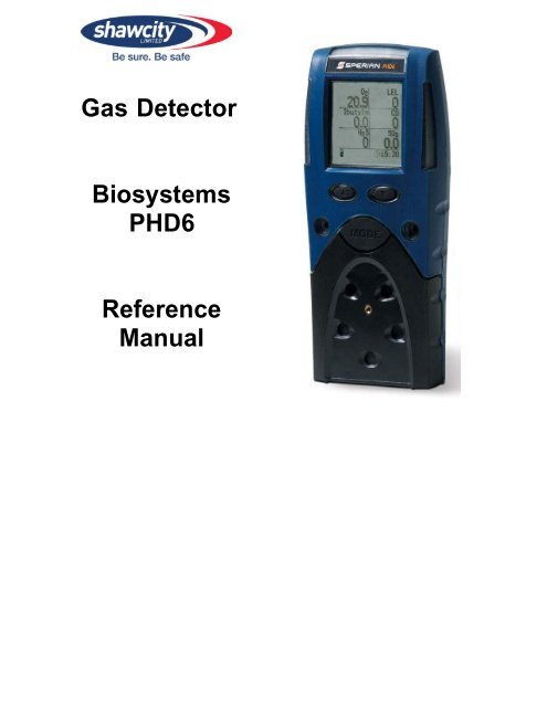
<strong>Gas</strong> <strong>Detector</strong><br />
<strong>Biosystems</strong><br />
<strong>PHD6</strong><br />
<strong>Reference</strong><br />
<strong>Manual</strong>
BIOSYSTEMS <strong>PHD6</strong> PERSONAL PORTABLE GAS DETECTORS HAVE<br />
BEEN DESIGNED FOR THE DETECTION AND MEASUREMENT OF<br />
POTENTIALLY HAZARDOUS ATMOSPHERIC CONDITIONS<br />
IN ORDER TO ASSURE THAT THE USER IS PROPERLY WARNED OF<br />
POTENTIALLY DANGEROUS ATMOSPHERIC CONDITIONS, IT IS<br />
ESSENTIAL THAT THE INSTRUCTIONS IN THIS REFERENCE MANUAL<br />
BE READ, FULLY UNDERSTOOD, AND FOLLOWED.<br />
<strong>Biosystems</strong> <strong>PHD6</strong><br />
<strong>Reference</strong> <strong>Manual</strong><br />
Part Number 13-322<br />
Version 2.01<br />
Copyright 2009<br />
by<br />
Sperian Protection Instrumentation, LLC<br />
Middletown, Connecticut 06457<br />
All rights reserved.<br />
No page or part of this operation manual may be reproduced in any form without<br />
written permission of the copyright owner shown above.<br />
Sperian reserves the right to correct typographical errors.<br />
Specifications are subject to change without notice.<br />
1
Table of Contents<br />
CERTIFICATION INFORMATION 4<br />
OPERATING TEMPERATURE AND HUMIDITY LIMITS 4<br />
SIGNAL WORDS 4<br />
WARNINGS AND CAUTIONS 4<br />
1. DESCRIPTION 6<br />
1.1 Methods of sampling 6<br />
1.2 Multi-sensor capability 6<br />
1.3 Calibration 6<br />
1.4 Alarm logic 6<br />
1.4.1 Atmospheric hazard alarms 7<br />
1.4.2 Low battery alarms 7<br />
1.4.3 Sensor over range alarms 7<br />
1.4.4 PID lamp out alarm 7<br />
1.4.5 LEL response failure due to lack of O 2 alarm 7<br />
1.4.6 Security beep/flash 7<br />
1.4.7 Latching alarms 7<br />
1.4.8 Fault detection 8<br />
1.5 Other electronic safeguards 8<br />
1.6 Sensors 8<br />
1.7 Optional sample draw pump 8<br />
1.7.1 Special precautions when using the <strong>PHD6</strong> pump 8<br />
1.8 Data storage 8<br />
1.8.1 Black box data recorder 9<br />
1.8.2 Event logger 9<br />
1.9 <strong>PHD6</strong> design components 9<br />
1.10 <strong>PHD6</strong> standard accessories 9<br />
1.10.1 Alkaline <strong>PHD6</strong> detectors 10<br />
1.10.2 Li-Ion <strong>PHD6</strong> detectors 10<br />
1.11 <strong>PHD6</strong> kits 10<br />
1.11.1 <strong>PHD6</strong> Confined Space Kits 10<br />
1.11.2 <strong>PHD6</strong> Value Packs 10<br />
2. BASIC OPERATIONS 10<br />
2.1 Turning the <strong>PHD6</strong> On 10<br />
2.1.1 Start up with pump 11<br />
2.1.2 Start up with PID or IR sensor 11<br />
2.2 Operating Logic 11<br />
2.2.1 Status Bar 11<br />
Battery Status Icon 11<br />
Heartbeat Symbol 12<br />
Pump Status Icon 12<br />
Calibration and Bump Due Warnings 12<br />
Time 12<br />
2.2.2 Screen Flip 12<br />
2.3 Turning the <strong>PHD6</strong> Off 12<br />
2.4 Atmospheric Hazard Alarms 12<br />
2.4.1 O2 Alarms 12<br />
2.4.2 Combustible <strong>Gas</strong> Alarms 12<br />
2.4.3 Toxic and VOC sensor alarms 12<br />
2.4.4 Alarm Descriptions 12<br />
Warning Alarms 12<br />
Danger Alarms 13<br />
STEL Alarms 13<br />
TWA Alarms 13<br />
2.5 Other Alarms 13<br />
2.5.1 Missing Sensor Alarms 13<br />
2.5.2 Sensor Overrange alarm 13<br />
2.5.3 PID Lamp Out Alarm 13<br />
2.5.4 O 2 Too Low for LEL Alarms 13<br />
2.5.5 Low Battery Alarms 13<br />
2.5.6 Calibration Due Warning 14<br />
2.5.7 Out of Temperature Range 14<br />
2
2.6 PC Connection via Infrared Port 14<br />
2.7 PID sensor reactivity ratios 14<br />
2.7.1 Displayed VOC 14<br />
2.7.2 Specified VOC Calibration <strong>Gas</strong> 15<br />
2.8 Special Instructions for NDIR sensors 15<br />
2.8.1 Special Calibration Requirement for NDIR CO 2 (Carbon Dioxide) Sensor 15<br />
2.8.3 Hydrogen Warning for IR CH 4 Methane Sensor 15<br />
3. SAMPLING 15<br />
3.1 <strong>Manual</strong> sample draw kit 15<br />
3.1.1 <strong>Manual</strong> sample draw kit usage 15<br />
3.2 Motorized sample draw pump 16<br />
3.2.1 Starting the motorized sample pump 16<br />
3.2.2 Turning off the pump 17<br />
3.2.3 Pump low flow alarm 17<br />
3.3 Sample draw probe 17<br />
4. CALIBRATION 17<br />
4.1 Functional (Bump) testing 18<br />
4.2 Fresh Air/Zero Calibration 18<br />
4.2.1 Fresh air calibration failure 19<br />
4.2.2 Forced fresh air calibration 19<br />
4.2.3 Fresh air calibration in a contaminated atmosphere 19<br />
4.3 <strong>Gas</strong> Calibration 19<br />
4.3.1 <strong>Gas</strong> calibration failure: All sensors except oxygen 20<br />
4.3.2 <strong>Gas</strong> calibration failure: Oxygen sensors 20<br />
4.4 Special Calibration Instruction for NDIR CO 2 sensor 21<br />
4.4.1 CO 2 Sensor True Zero 21<br />
4.5 Special Calibration Instructions for NDIR-CH 4 Sensor 21<br />
5. MENU OPTIONS 21<br />
5.1 Basic Menu 21<br />
5.1.1 Entering the Basic Menu 21<br />
5.2 Main Menu 21<br />
5.2.1 Entering the Main Menu 22<br />
5.2.2 Using the submenus. 22<br />
5.2.3 Alarms Menu 22<br />
5.2.4 Calibration Menu 22<br />
5.2.5 Configuration Menu 23<br />
5.2.6 Screen Menu 24<br />
5.2.7 Information Menu 24<br />
5.2.8 Datalogger Menu 24<br />
6. MAINTENANCE 24<br />
6.1 Batteries 24<br />
6.2 Replacing alkaline batteries 24<br />
6.3 Maintaining Li-Ion battery packs 25<br />
6.3.1 Storage guidelines for the Li-Ion battery 25<br />
6.3.2 Charging guidelines for Li-Ion battery 25<br />
6.3.3 Charging procedure for Li-Ion battery 25<br />
6.3.4 Charging with the pump attached 25<br />
6.3.5 Battery troubleshooting 25<br />
6.4 Sensors 25<br />
6.4.1 Sensor replacement 25<br />
6.4.2 Care and maintenance of PID sensors 26<br />
6.4.2.1 Troubleshooting the PID 26<br />
6.4.2.2 Cleaning and replacing PID components 26<br />
6.5 Sample probe assembly 26<br />
6.5.1 Changing sample probe filters 27<br />
6.5.2 Changing sample probe tubes (wands) 27<br />
6.6 <strong>PHD6</strong> Pump Maintenance 27<br />
6.6.1 Replacing pump filters 27<br />
APPENDICES 28<br />
Appendix A Toxic gas measurement – Warning, Danger, STEL and TWA alarms 28<br />
1. Warning and Danger Alarms 28<br />
2. Time Weighted Average (TWA) 28<br />
3. Short Term Exposure Limits (STEL) 28<br />
Appendix B Calibration Frequency Recommendation 29<br />
3
Appendix C <strong>PHD6</strong> Sensor Information 30<br />
Appendix D Electrochemical Toxic Sensor Cross-Sensitivity 30<br />
** SENSOR MANUFACTURER RATES CROSS SENSITIVITY FOR HCN SENSOR TO H2S AS FOLLOWS FOR 20<br />
PPM EXPOSURE: “SHORT GAS EXPOSURE IN MINUTE RANGE; AFTER FILTER SATURATION: CA. 40 PPM<br />
READING”.SPERIAN INSTRUMENTATION WARRANTY GAS DETECTION PRODUCTS 30<br />
SPERIAN INSTRUMENTATION WARRANTY GAS DETECTION PRODUCTS 31<br />
Certification Information<br />
The <strong>PHD6</strong> carries the following certifications (as of 6/1/2008):<br />
SGS USTC Class I Division 1 Groups A,B,C,D Temp Code T3C (Approved to UL 913)<br />
SGS USTC Class II Division 1 Groups E,F,G (Approved to UL 913)<br />
SGS USTC Class III (Approved to UL 913)<br />
CSA Class I, Division 1 Groups A,B,C,D Temp Code T3C<br />
ONLY THE COMBUSTIBLE GAS DETECTION PORTION OF THIS INSTRUMENT HAS BEEN ASSESSED<br />
FOR PERFORMANCE.<br />
ATEX: Ex d ia IIC 170 °C (T3)<br />
IECEx: Ex d ia IIC 170 °C (T3)<br />
Operating Temperature and Humidity Limits<br />
The <strong>Biosystems</strong> <strong>PHD6</strong>’s operating temperature range is printed on the<br />
label on the back of the instrument. Use of Sperian <strong>Gas</strong> <strong>Detector</strong>s outside of the<br />
instrument’s specified operating temperature range may result in inaccurate and potentially<br />
dangerous readings.<br />
Signal Words<br />
The following signal words, as defined by ANSI Z535.4-1998, are used in the <strong>PHD6</strong><br />
<strong>Reference</strong> <strong>Manual</strong>.<br />
indicates an imminently hazardous situation which, if not avoided, will<br />
result in death or serious injury.<br />
indicates a potentially hazardous situation which, if not avoided, could<br />
result in death or serious injury.<br />
indicates a potentially hazardous situation, which if not avoided, may<br />
result in moderate or minor injury.<br />
CAUTION used without the safety alert symbol indicates a potentially hazardous<br />
situation which, if not avoided, may result in property damage.<br />
Warnings and Cautions<br />
1.<br />
2.<br />
3.<br />
4.<br />
5.<br />
6.<br />
The <strong>PHD6</strong> personal, portable gas detector has been designed for<br />
the detection of dangerous atmospheric conditions. An alarm condition indicates the<br />
presence of a potentially life-threatening hazard and should be taken very seriously.<br />
Failure to immediately leave the area may result in serious injury or death.<br />
In the event of an alarm condition it is important to follow<br />
established procedures. The safest course of action is to immediately leave the affected<br />
area, and to return only after further testing determines that the area is once again safe<br />
for entry. Failure to immediately leave the area may result in serious injury or death.<br />
The <strong>PHD6</strong> must be located in a non-hazardous location whenever<br />
alkaline batteries are removed from the alkaline battery pack. Removal of the alkaline<br />
batteries from the battery pack in a hazardous area may impair intrinsic safety.<br />
Use only Duracell MN1500 or Ultra MX1500, Eveready Energizer<br />
E91-LR6, Eveready EN91 batteries in the alkaline battery pack. Substitution of batteries<br />
may impair intrinsic safety.<br />
To reduce the risk of explosion, do not mix old or used batteries<br />
with new batteries and do not mix batteries from different manufacturers.<br />
Do not charge the <strong>PHD6</strong> with any charger other than the<br />
appropriate Sperian <strong>PHD6</strong> charger. Standard versions of the <strong>PHD6</strong> must be charged<br />
4
7.<br />
8.<br />
9.<br />
10.<br />
with the UL/CSA-approved charger, which is Sperian part number 54-49-103-1.<br />
European versions of the <strong>PHD6</strong> must be charged with the ATEX-approved charger,<br />
which is Sperian part number 54-49-103-5.<br />
The <strong>PHD6</strong> must be located in a non-hazardous location during the<br />
charging cycle. Charging the <strong>PHD6</strong> in a hazardous location may impair intrinsic safety.<br />
<strong>PHD6</strong> rechargeable battery packs are supplied with Panasonic<br />
CGR18650D Lithium-Ion batteries. The Li-Ion batteries in the battery packs may not be<br />
replaced by the user. The rechargeable pack must be obtained from Sperian and<br />
replaced as a complete assembly to maintain intrinsic safety.<br />
The accuracy of the <strong>PHD6</strong> should be checked periodically with<br />
known concentration calibration gas. Failure to check accuracy can lead to inaccurate<br />
and potentially dangerous readings. (The Canadian Standards Association (CSA)<br />
requires an accuracy check using known concentration calibration gas prior to each<br />
day’s use.)<br />
Fresh air/zero calibrations may only be performed in an<br />
atmosphere that is known to contain 20.9% oxygen, 0.0% LEL and 0 PPM toxic gas.<br />
11. The accuracy of the <strong>PHD6</strong> should be checked immediately<br />
following any known exposure to contaminants by testing with known concentration test<br />
gas before further use. Failure to check accuracy can lead to inaccurate and potentially<br />
dangerous readings.<br />
12. A sensor that cannot be calibrated or is found to be out of<br />
tolerance should be replaced immediately. An instrument that fails calibration may not<br />
be used until testing with known concentration test gas determines that accuracy has<br />
been restored, and the instrument is once again fit for use.<br />
13. Do not reset the calibration gas concentration unless you are using<br />
a calibration gas concentration that differs from the one that is normally supplied by<br />
Sperian for use in calibrating the <strong>PHD6</strong>.<br />
Customers are strongly urged to use only Sperian calibration materials when calibrating<br />
the <strong>PHD6</strong>. Use of non-standard calibration gas and/or calibration kit components can lead<br />
to dangerously inaccurate readings and may void the standard Sperian warranty.<br />
14. Use of non-standard calibration gas and/or calibration kit<br />
components when calibrating the <strong>PHD6</strong> can lead to inaccurate and potentially<br />
dangerous readings and may void the standard Sperian warranty.<br />
Sperian offers calibration kits and long-lasting cylinders of test gas specifically<br />
developed for easy <strong>PHD6</strong> calibration. Customers are strongly urged to use only Sperian<br />
calibration materials when calibrating the <strong>PHD6</strong>.<br />
15.<br />
Substitution of components may impair intrinsic safety.<br />
16.<br />
For safety reasons this equipment must be operated and serviced<br />
by qualified personnel only. Read and understand this reference manual before<br />
operating or servicing the <strong>PHD6</strong>.<br />
17.<br />
A rapid up-scale reading followed by a declining or erratic reading<br />
may indicate a hazardous combustible gas concentration that exceeds the <strong>PHD6</strong>’s zero<br />
to 100 percent LEL detection range.<br />
18.<br />
The <strong>PHD6</strong> is not designed for use in oxygen enriched<br />
atmospheres.<br />
19.<br />
Do not use the <strong>PHD6</strong> pump for prolonged periods in an<br />
atmosphere containing a concentration of solvent or fuel that may be greater than 50%<br />
LEL.<br />
20. Do not unplug the NDIR-CH 4 or NDIR-CO 2 sensors in an explosive<br />
atmosphere. Unplugging IR sensors in an explosive atmosphere may impair intrinsic<br />
safety.<br />
5
1. Description<br />
The <strong>Biosystems</strong> <strong>PHD6</strong> is a multi-sensor gas<br />
detector that can be configured to meet a wide<br />
variety of user requirements. This chapter<br />
provides an overview of many of the features of<br />
the <strong>PHD6</strong>. More detailed descriptions of the<br />
specific features of the <strong>PHD6</strong> are contained in the<br />
subsequent chapters of this manual.<br />
1.1 Methods of sampling<br />
The <strong>PHD6</strong> may be used in either diffusion or<br />
sample-draw mode. In either mode, the gas<br />
sample must reach the sensors for the instrument<br />
to register a gas reading. The sensors are<br />
located at the lower front of the instrument.<br />
The sensor ports must be<br />
kept free of obstruction. Blocked sensor<br />
ports can lead to inaccurate and potentially<br />
dangerous readings.<br />
In diffusion mode, the atmosphere being<br />
measured reaches the sensors by diffusing<br />
through the sensor ports at the front of the<br />
instrument. Normal air movements are enough to<br />
carry the sample to the sensors. The sensors<br />
react quickly to changes in the concentrations of<br />
the gases being measured. Diffusion-style<br />
operation monitors only the atmosphere that<br />
immediately surrounds the detector.<br />
The <strong>PHD6</strong> can also be used to sample remote<br />
locations with its hand-aspirated sample-draw kit<br />
or with its motorized, continuous sample draw<br />
pump. During remote sampling, the gas sample<br />
is drawn into the sensor compartment through the<br />
probe assembly and a length of tubing. Remote<br />
sampling operations only monitor the atmosphere<br />
at the end of the sample draw probe.<br />
Use of the hand-aspirated sample draw kits is<br />
covered in section 3.1.<br />
Use of the motorized sample draw pump is<br />
covered in section 3.2.<br />
A detailed description of the <strong>PHD6</strong> probe<br />
assembly is given in section 6.5<br />
1.2 Multi-sensor capability<br />
The <strong>PHD6</strong> can be configured to simultaneously<br />
monitor oxygen, combustible gases and vapors,<br />
volatile organic compounds (VOCs), and a wide<br />
6<br />
variety of toxic gases. All sensors are<br />
replaceable in the field.<br />
Note: The accuracy of the <strong>PHD6</strong> must be<br />
verified by calibration with known<br />
concentration test gas whenever a change is<br />
made to the sensors installed in the<br />
instrument.<br />
Calibration procedures are discussed in detail<br />
in Chapter 4.<br />
The <strong>PHD6</strong> can utilize a variety of sensor types to<br />
detect atmospheric contaminants including<br />
electrochemical sensors, PID (Photo Ionization<br />
<strong>Detector</strong>) sensors, NDIR (Non-Dispersive Infra-<br />
Red Absorbance) sensors and catalytic hot-bead<br />
LEL sensors.<br />
Different measurement units are used depending<br />
on the gas being measured.<br />
Type of Hazard<br />
Oxygen (O 2 )<br />
Combustible gas<br />
(LEL Sensor)<br />
Measurement unit<br />
Percentage by<br />
volume<br />
Percentage of lower<br />
explosive limit<br />
(%LEL) or %/Vol CH 4<br />
Percentage of lower<br />
explosive limit<br />
(%LEL) or transitional<br />
Hydrocarbon-specific<br />
combustible gas<br />
sensor<br />
(NDIR – CH 4 ) PPM - %/Vol CH 4<br />
Parts-per-million<br />
Volatile Organic<br />
(PPM) or tenths of a<br />
Compounds (VOCs)<br />
part-per-million<br />
(PID Sensor)<br />
(0.1PPM)<br />
Parts-per-million<br />
Toxic <strong>Gas</strong>es (by<br />
(PPM) – some<br />
electrochemical<br />
sensors capable of<br />
sensor or by NDIR –<br />
tenths of a part-per-<br />
CO 2 sensor)<br />
million (0.1PPM)<br />
Table 1.2. <strong>PHD6</strong> Units of Measurement.<br />
1.3 Calibration<br />
The <strong>PHD6</strong> detector features fully automatic fresh<br />
air and gas calibration.<br />
The accuracy of the<br />
<strong>PHD6</strong> should be checked periodically with<br />
known concentration calibration gas. Failure<br />
to check accuracy can lead to inaccurate and<br />
potentially dangerous readings. (The<br />
Canadian Standards Association (CSA)<br />
requires an accuracy check using known<br />
concentration calibration gas prior to each<br />
day’s use.)<br />
Calibration procedures are discussed in detail<br />
in Chapter 4.<br />
Recommended calibration frequency is<br />
discussed in Appendix B.<br />
1.4 Alarm logic<br />
<strong>PHD6</strong> gas alarms can be adjusted manually<br />
using the <strong>PHD6</strong>’s built in menu functions, with<br />
BioTrak software via IrDA interface, or with the IQ<br />
Database Manager Program through the <strong>PHD6</strong>
IQ Express Dock. (See Chapter 6 for direct<br />
menu programming instructions). Alarms may be<br />
set anywhere within the nominal range of the<br />
specific sensor. When an alarm set point is<br />
exceeded a loud audible alarm sounds, and the<br />
bright red LED alarm lights flash.<br />
1.4.1 Atmospheric hazard alarms<br />
<strong>PHD6</strong> portable gas<br />
detectors have been designed for the<br />
detection of deficiencies of oxygen,<br />
accumulations of flammable gases and<br />
vapors, and accumulations of specific toxic<br />
gases. An alarm condition indicating the<br />
presence of one or more of these potentially<br />
life-threatening hazards should be taken very<br />
seriously. Failure to immediately leave the<br />
area may result in serious injury or death.<br />
In the event of an alarm<br />
condition it is important to follow established<br />
procedures. The safest course of action is to<br />
immediately leave the affected area, and to<br />
return only after further testing determines<br />
that the area is once again safe for entry.<br />
Failure to immediately leave the area may<br />
result in serious injury or death.<br />
A rapid up-scale reading<br />
followed by a declining or erratic reading may<br />
indicate a hazardous combustible gas<br />
concentration that exceeds the <strong>PHD6</strong>’s zero<br />
to 100 percent LEL detection range. Failure to<br />
immediately leave the area may result in<br />
serious injury or death.<br />
The combustible gas alarms are activated when<br />
the reading for combustible gases exceeds one<br />
of the alarm setpoints. Combustible gas readings<br />
are typically given in terms of percent of LEL<br />
(Lower Explosive Limit), but may also be shown<br />
in terms of percent-by-volume methane (CH 4 ).<br />
The <strong>PHD6</strong> includes Warning and Danger alarms<br />
for the both the LEL sensor and the NDIR-CH 4<br />
sensor.<br />
Two oxygen alarm set points have been<br />
provided; a low alarm for oxygen deficiency and a<br />
high alarm for oxygen enrichment.<br />
Up to four alarm set points are provided for the<br />
PID sensor and for each toxic gas sensor:<br />
Warning, Danger, STEL (Short Term Exposure<br />
Limit) and TWA (Time Weighted Average).<br />
Appendix A discusses Warning, Danger,<br />
STEL and TWA alarms.<br />
1.4.2 Low battery alarms<br />
The <strong>PHD6</strong> includes multi-staged alarms for both<br />
the Li-Ion and alkaline battery packs to let the<br />
user know that the battery is running low.<br />
For detailed information concerning the low<br />
battery alarms, see section 2.5.5.<br />
Use only Duracell MN1500<br />
or Ultra MX1500, Eveready Energizer E91-LR6,<br />
Eveready EN91 batteries. Substitution of<br />
batteries may impair intrinsic safety.<br />
1.4.3 Sensor over range alarms<br />
The <strong>PHD6</strong> will go into alarm if a sensor is<br />
exposed to a concentration of gas that exceeds<br />
its established range. In the case of an LEL or<br />
NDIR-CH 4 sensor reading that exceeds 100%<br />
LEL, the sensor channel will be automatically<br />
disabled by the instrument and the instrument will<br />
remain in constant alarm until it is turned off,<br />
brought to an area that is known to be safe, and<br />
then turned back on. The display will show a<br />
vertical arrow with two heads in place of the<br />
sensor reading for any channel that has gone into<br />
over range alarm.<br />
See section 2.5.2 for further details.<br />
In the event of an LEL<br />
overrange alarm the <strong>PHD6</strong> must be turned off,<br />
brought to an area that is known to be safe<br />
and then turned on again to reset the alarm.<br />
1.4.4 PID lamp out alarm<br />
The <strong>PHD6</strong> monitors the status of the PID lamp to<br />
ensure that it is functioning properly. Alarms are<br />
generated if the <strong>PHD6</strong> determines that the lamp<br />
is out. See section 2.5.3 for further details<br />
1.4.5 LEL response failure due to lack of O 2<br />
alarm<br />
The <strong>PHD6</strong> features automatic warning against<br />
LEL sensor response failure due to lack of<br />
oxygen. See section 2.5.4 for details.<br />
1.4.6 Security beep/flash<br />
The <strong>PHD6</strong> includes a security beep function that<br />
is designed to notify the user that the instrument<br />
is powered up and running. Once enabled the<br />
<strong>PHD6</strong> will emit a short audible beep and give a<br />
short flash on the LED at a user-defined interval.<br />
The security beep/flash can be enabled manually<br />
through the Main Menu (see chapter 5), with<br />
BioTrak software or through the <strong>PHD6</strong> IQ<br />
Express Dock.<br />
1.4.7 Latching alarms<br />
The <strong>PHD6</strong>’s alarms are self-resetting unless the<br />
alarm latch is enabled. With the <strong>PHD6</strong>’s alarm<br />
latch enabled, the audible and visible alarms will<br />
continue to sound after the atmospheric hazard<br />
has cleared. To reset the alarms, simply press<br />
the MODE button. If the alarm latch is disabled<br />
and the alarm condition is no longer present, the<br />
instrument will automatically return to normal<br />
operation, and the visible and audible alarms<br />
cease without further input from the user.<br />
Latching alarms can be enabled manually<br />
through the Main Menu (see chapter 5), with<br />
BioTrak software or through the <strong>PHD6</strong> IQ<br />
Express Dock.<br />
7
1.4.8 Fault detection<br />
<strong>PHD6</strong> software includes a number of additional<br />
alarms designed to ensure the proper operation<br />
of the instrument. When the <strong>PHD6</strong> detects that<br />
an electronic fault or failure condition has<br />
occurred, the proper audible and visible alarms<br />
are activated and an explanatory message is<br />
displayed.<br />
Faults and other electronic safeguards are<br />
discussed in detail in section 2.5.<br />
The <strong>PHD6</strong> is designed to<br />
detect potentially life threatening atmospheric<br />
conditions. Any alarm condition should be<br />
taken seriously. The safest course of action<br />
is to immediately leave the affected area, and<br />
return only after further testing determines<br />
that the area is once again safe for entry.<br />
1.5 Other electronic safeguards<br />
Several automatic programs prevent tampering<br />
and misuse of the <strong>PHD6</strong> by unauthorized<br />
persons. Each time the detector is turned on, the<br />
<strong>PHD6</strong> automatically tests the LED alarm lights,<br />
audible alarm, internal memory and pump status<br />
(if so equipped). The battery is monitored<br />
continuously for proper voltage. The <strong>PHD6</strong> also<br />
monitors the connection of sensors that are<br />
currently installed. The detection of any<br />
electronic faults causes the activation of the<br />
audible and visible alarms and causes the display<br />
of the appropriate explanatory message.<br />
1.6 Sensors<br />
The <strong>PHD6</strong> can be configured to simultaneously<br />
monitor oxygen, combustible gases and vapors,<br />
volatile organic compounds (VOCs) and a<br />
number of toxic gases. The sensor configuration<br />
of the <strong>PHD6</strong> may be specified at the time of<br />
purchase, or changed in the field by appropriately<br />
trained personnel.<br />
The <strong>PHD6</strong> must be calibrated following any<br />
sensor replacement.<br />
Replacement sensor part numbers and<br />
sensor ranges are given in Appendix C.<br />
A sensor that cannot be<br />
calibrated or is found to be out of tolerance<br />
must be replaced immediately. An instrument<br />
that fails calibration may not be used until<br />
testing with known concentration test gas<br />
determines that accuracy has been restored,<br />
and the instrument is once again fit for use.<br />
Calibration procedures are discussed in detail<br />
in Chapter 4.<br />
1.6.1 Cross Sensitivity<br />
Sensor cross-sensitivity figures are given in<br />
Appendix D.<br />
The CO channel in the Duo-Tox sensor in the<br />
<strong>PHD6</strong> may exhibit high levels of cross sensitivity<br />
to organic vapors (VOCs). For best performance<br />
in an atmosphere known to contain VOCs, use a<br />
dedicated CO sensor.<br />
1.7 Optional sample draw pump<br />
A motorized sample-draw pump is available for<br />
the <strong>PHD6</strong> for situations requiring continuous<br />
"hands free" remote monitoring.<br />
The <strong>PHD6</strong> continuous<br />
sample draw pump (Sperian Instrumentation<br />
part number 54-54-102) is the only pump that<br />
can be used with the <strong>PHD6</strong>.<br />
The pump contains a pressure<br />
sensor that detects restrictions in<br />
airflow caused by water or other<br />
obstructions being drawn into the<br />
unit and immediately acts to turn<br />
the pump off in order to protect<br />
the sensors, pump, and other<br />
<strong>PHD6</strong> components from damage.<br />
Pump status is continuously<br />
monitored by the <strong>PHD6</strong><br />
microcontroller. When the pump<br />
is active and functioning properly,<br />
the spinning pump icon is displayed in the status<br />
bar at the bottom of the display. Low flow or<br />
other pump fault conditions activate audible and<br />
visible alarms and cause the display of the<br />
appropriate explanatory message.<br />
1.7.1 Special precautions when using the<br />
<strong>PHD6</strong> pump<br />
The internal material used in the <strong>PHD6</strong>’s pump<br />
diaphragm seal is susceptible to temporary<br />
compromise by high levels of combustible fuels<br />
and solvents. If the <strong>PHD6</strong> is being used in an<br />
atmosphere that may contain concentrations of<br />
combustible fuels and solvents that exceed 50%<br />
LEL, test the pump frequently to ensure that the<br />
seals have not been compromised.<br />
To test the pump, block the sample inlet with a<br />
finger. The pump should go into alarm. If the<br />
pump fails to go into alarm while the inlet is<br />
blocked, the pump is not working properly and<br />
the <strong>PHD6</strong> may not be providing an accurate<br />
reading. If the pump test fails, the safest course<br />
of action is to immediately leave the affected<br />
area, and return only after further testing<br />
determines that the area is once again safe for<br />
entry.<br />
Do not use the pump for<br />
prolonged periods in an atmosphere<br />
containing a concentration of solvent or fuel<br />
that may be greater than 50% LEL.<br />
1.8 Data storage<br />
The <strong>PHD6</strong> includes a black box data recorder<br />
and an event logger as standard features. A full<br />
datalogger is available as an upgrade at any<br />
time.<br />
8
1.8.1 Black box data recorder<br />
A black box data recorder is a standard feature in<br />
the <strong>PHD6</strong>. The “black box” is continually in<br />
operation whether the user is aware of it or not.<br />
The black box stores important information such<br />
as gas readings, turn-on times, turn-off times,<br />
temperatures, battery conditions, the most recent<br />
calibration date and settings, types of sensors<br />
currently installed, sensor serial numbers,<br />
warranty expiration and service due dates, and<br />
current alarm settings.<br />
There is a finite amount of memory storage<br />
available in the black box data recorder. Once<br />
the memory is “full”, the <strong>PHD6</strong> will begin to write<br />
the new data over the oldest data. The black box<br />
data recorder will store a minimum of 63 hours of<br />
data in one-minute increments before it begins to<br />
write new data over the oldest data. In this way,<br />
the newest data is always conserved.<br />
To extract the information from the black box data<br />
recorder, the <strong>PHD6</strong> must be returned to Sperian.<br />
Once the data is downloaded from the<br />
instrument, a report will be generated. The unit<br />
and the report will then be returned to the user.<br />
Simply call Sperian’s Instrument Service<br />
Department to obtain a return authorization<br />
number. There is no charge for the downloading<br />
service, but the user is responsible for any freight<br />
charges incurred.<br />
The “black box” data recorder in the <strong>PHD6</strong> can<br />
be upgraded to a fully enabled datalogger at any<br />
time. All that is required is the activation code<br />
that corresponds to the serial number of the<br />
<strong>PHD6</strong> and the <strong>PHD6</strong> Upgrade Utility Program.<br />
1.8.2 Event logger<br />
The event logger in the <strong>PHD6</strong> stores data<br />
associated with alarm conditions. Each (alarm)<br />
event includes the following data for each of the<br />
installed sensors:<br />
• Sensor type<br />
• Max reading<br />
• Average reading<br />
• Start time<br />
• End time<br />
• Duration of the event.<br />
The <strong>PHD6</strong> stores the data from the 20 most<br />
recent alarm events. Once 20 events have been<br />
stored, the <strong>PHD6</strong> will begin to systematically<br />
overwrite the data from the oldest event in<br />
memory with data from new events. One event<br />
may be a combination of different alarms<br />
occurring simultaneously or in immediate<br />
succession. The event logger may be<br />
downloaded using BioTrak software. The PC<br />
must be equipped with IrDA to provide a<br />
connection.<br />
1.9 <strong>PHD6</strong> design components<br />
1. Case: The instrument is enclosed in a solid<br />
PC (polycarbonate) case with TPE (rubber)<br />
overmold.<br />
2. Front face: The front face of the instrument<br />
houses the MODE button, navigation keys,<br />
LCD (liquid crystal display), LED alarm lights,<br />
and audible alarm ports.<br />
3. Display: A liquid crystal display (LCD)<br />
shows readings, messages, and other<br />
information.<br />
4. Alarm LEDs: Top, front and side-mounted<br />
LED (light emitting diode) alarm lights provide<br />
a visual indication of alarm state.<br />
5. Infrared Port: The infrared port is located at<br />
the bottom of the instrument and is used for<br />
communication between the <strong>PHD6</strong> and a PC.<br />
6. On / Off "MODE" button: The large black<br />
push-button on the front of the instrument is<br />
the "MODE" button. The MODE button is<br />
used to turn the <strong>PHD6</strong> on and off as well as<br />
to control most other operations, including<br />
the initiation of the automatic calibration<br />
adjustment.<br />
7. Navigation Keys: The up and down<br />
navigation keys are located between the<br />
MODE button and the display.<br />
8. Sensor compartment cover: The sensors<br />
are located in a vented compartment at the<br />
bottom of the instrument.<br />
9. Audible alarm ports: Two cylindrical ports<br />
extending through the front of the instrument<br />
on opposing sides of the MODE button house<br />
the loud audible alarms. The waterproof<br />
audible alarms seat directly to the rubber<br />
inner-liner to protect the instrument against<br />
leakage or exposure to liquids.<br />
10. Battery pack: Two types of interchangeable<br />
battery packs (rechargeable Lithium Ion (Li-<br />
Ion) and disposable alkaline) are available for<br />
use. Li-Ion battery packs are recharged with<br />
the pack installed on the <strong>PHD6</strong>.<br />
11. Battery charger connector: A waterresistant<br />
connector at the bottom of the case<br />
assembly is used to connect the <strong>PHD6</strong> to the<br />
“drop in” style charger.<br />
12. Battery Compartment / Clip: The battery<br />
inserts from the back of the instrument. A<br />
sturdy clip attached to the battery allows the<br />
user to wear the <strong>PHD6</strong> on a belt or other<br />
article of clothing.<br />
1.10 <strong>PHD6</strong> standard accessories<br />
Standard accessories included with every <strong>PHD6</strong><br />
include calibration adapter, additional tubing for<br />
use during calibration, manual sample draw kit,<br />
reference manual and quick reference card. The<br />
manual sample draw kit consists of a sample<br />
draw / calibration adapter, squeeze bulb,<br />
replacement sample probe filters, ten feet of<br />
tubing and a sample probe.<br />
9
Standard configurations of the <strong>PHD6</strong> are<br />
delivered in a cardboard box with cardboard<br />
inserts.<br />
1.10.1 Alkaline <strong>PHD6</strong> detectors<br />
If the <strong>PHD6</strong> has been purchased as an alkaline<br />
instrument, the standard accessories include an<br />
alkaline battery pack and a set of 3 disposable<br />
AA alkaline batteries.<br />
1.10.2 Li-Ion <strong>PHD6</strong> detectors<br />
If the <strong>PHD6</strong> has been purchased as a Li-Ion<br />
rechargeable instrument, the standard<br />
accessories include Li-Ion battery pack and a<br />
slip-in <strong>PHD6</strong> charger.<br />
1.11 <strong>PHD6</strong> kits<br />
<strong>PHD6</strong> detectors may also be purchased as part<br />
of a complete kit that includes calibration gas,<br />
fixed-flow regulator and a hard-shell carrying<br />
case.<br />
1.11.1 <strong>PHD6</strong> Confined Space Kits<br />
In addition to the standard accessories listed<br />
above, Confined Space Kits also include<br />
calibration fittings, fixed-flow regulator with<br />
pressure gauge, and appropriate large cylinder(s)<br />
of calibration gas in a foam-lined, waterproof<br />
hard-shell carrying case.<br />
1.11.2 <strong>PHD6</strong> Value Packs<br />
<strong>PHD6</strong> Value Packs include an alkaline <strong>PHD6</strong>, all<br />
standard accessories, calibration fittings, small<br />
cylinder of calibration gas, and fixed flow<br />
regulator in a foam-lined non-waterproof hardshell<br />
carrying case.<br />
2. Basic Operations<br />
The <strong>PHD6</strong> is a three-button gas detector. Most<br />
day-to-day functions are initiated solely with the<br />
MODE button. The MODE button controls:<br />
• Turning the <strong>PHD6</strong> on and off<br />
• Turning on the backlight<br />
• Viewing the MAX, STEL and TWA reading<br />
screens<br />
• Initiating the calibration sequence<br />
2.1 Turning the <strong>PHD6</strong> On<br />
To turn the <strong>PHD6</strong> on, press and hold the MODE<br />
button for one second. The introduction screen is<br />
followed by a screen showing a list of installed<br />
sensors and the sensor ports they occupy. The<br />
<strong>PHD6</strong> has 5 sensor ports, but can display<br />
readings for as many as 6 distinct gases.<br />
The serial number will then<br />
be shown. If the detector<br />
has a fully enabled<br />
datalogger, the interval and<br />
memory capacity will be<br />
shown.<br />
The sampling interval is<br />
given in minutes and<br />
seconds. The datalogger<br />
samples continuously, so the data stream must<br />
be broken into intervals to be recorded. The<br />
datalogging interval defines the frequency of the<br />
breaks in the data stream. The capacity is the<br />
number of hours and minutes it will take to<br />
completely fill the datalogger’s memory. Once<br />
the memory is filled, the <strong>PHD6</strong> will start to write<br />
new data over the oldest data in order to<br />
conserve that most recent data.<br />
The sampling interval in the fully enabled<br />
datalogger may be modified using BioTrak<br />
Software, the IQ Systems or manually through<br />
the Main Menu.<br />
If the <strong>PHD6</strong> is equipped with<br />
the standard black box<br />
datalogger, it will show Black<br />
Box.<br />
In the <strong>PHD6</strong>, a one-minute<br />
sampling interval will result in<br />
the ability to store a minimum<br />
of 63 hours of readings<br />
before the oldest data is overwritten by new data.<br />
If fewer than 5 sensors are used, the capacity will<br />
increase.<br />
As the instrument performs a<br />
basic electronic self test, the<br />
date, time, temperature and<br />
battery type will be<br />
displayed. During the selftest,<br />
the <strong>PHD6</strong> performs a<br />
system memory check and<br />
tests to see if a motorized<br />
pump is attached to the<br />
instrument. If a pump is detected, it will be briefly<br />
activated during the self-test. For details on start<br />
up procedures for pump-equipped <strong>PHD6</strong><br />
instruments see section 2.1.1 below.<br />
The <strong>PHD6</strong> will then display each installed sensor<br />
along with any associated alarms levels.<br />
→<br />
→<br />
→<br />
10
→<br />
For more information concerning atmospheric<br />
hazard alarms, see section 2.4.<br />
After the alarm screens, the <strong>PHD6</strong> will show that<br />
“Starting Session, Resetting Averages” followed<br />
by the calibrations status screen. Whenever the<br />
<strong>PHD6</strong> is turned on, it automatically starts a new<br />
operating session and resets STEL and TWA<br />
calculations. The MAX reading is also reset for<br />
the new session.<br />
→<br />
PID and IR readings that<br />
are displayed during the sensor warm up<br />
period should not be considered accurate.<br />
The use of the <strong>PHD6</strong> to monitor for<br />
compounds detected by the PID or IR sensor<br />
during the warm up period may lead to<br />
inaccurate and potentially dangerous<br />
readings.<br />
2.2 Operating Logic<br />
Once the <strong>PHD6</strong> has completed the start up<br />
sequence, the current gas readings screen will be<br />
shown. The status bar at the bottom of the<br />
display shows time plus calibration, pump and<br />
battery status.<br />
To turn on the backlight press the MODE button<br />
once. To view the peak readings screen, press<br />
the MODE button a second time. Press the<br />
MODE button a third time to view the Short Term<br />
Exposure Limit (STEL) and Time Weighted<br />
Averages (TWA) for the operating session.<br />
→<br />
If calibration is due and the calibration due<br />
warning is enabled, the user will need to<br />
acknowledge the calibration due status by<br />
pressing the MODE button. Once the MODE<br />
button is pressed, the <strong>PHD6</strong> will continue to the<br />
current gas readings screen<br />
and the appropriate<br />
calibration due icons will flash<br />
to remind the user that the<br />
instrument is past due for<br />
calibration. If calibration is<br />
not due, the number of days<br />
until the next calibration will<br />
be shown before the<br />
instrument proceeds to the current gas readings<br />
screen.<br />
2.1.1 Start up with pump<br />
<strong>PHD6</strong> instruments that are equipped with a builtin<br />
motorized sample draw pump will have a<br />
slightly longer start up sequence. After the<br />
calibration status screens, the <strong>PHD6</strong> will prompt<br />
you to leak test the pump.<br />
See section 3.2 for further instructions on<br />
using the <strong>PHD6</strong> pump.<br />
2.1.2 Start up with PID or IR sensor<br />
When a PID or IR sensor is<br />
installed in the <strong>PHD6</strong>, there will<br />
be a warm-up period during<br />
which the hourglass icon and<br />
either “PID” or “IR” will be shown.<br />
The VOC gas type and reading are<br />
shown in reverse text.<br />
Screens that are accessible with the MODE<br />
button (including the Peak and STEL/TWA<br />
screens) are selectable by the user. See section<br />
5.2.6 for details.<br />
Note: The <strong>PHD6</strong> must be in continuous<br />
operation for at least 15 minutes before it will<br />
be able to calculate STEL or TWA values. For<br />
the first 15 minutes of any operating session,<br />
the screen will show the length of time that<br />
the instrument has been operating instead of<br />
the STEL and TWA values.<br />
2.2.1 Status Bar<br />
The status bar at the bottom of the current gas<br />
readings shows general information including:<br />
Battery Status<br />
Heartbeat (instrument status)<br />
Pump Status<br />
PID Hourglass (PID warmup period)<br />
PID Lamp Status (shows “Check Sen.”)<br />
Bump Due Warning<br />
Calibration Due Warning<br />
Time<br />
Battery Status Icon<br />
The battery status icon is located at the far lower<br />
left of the screen. The battery icon gives an<br />
indication of how much power is left in the<br />
battery.<br />
11
When the battery icon is empty, it is<br />
considered a low battery condition and the<br />
user should take the appropriate steps to<br />
either recharge the Li-Ion battery or<br />
replace the alkaline batteries.<br />
For more information on the low<br />
battery alarms, see section 2.5.5.<br />
IR Hourglass Symbol<br />
The hourglass symbol along with IR<br />
are shown in the status bar during<br />
the IR sensor’s 1-minute warm-up<br />
period. Once the warm-up period is over, the<br />
hourglass will no longer be shown.<br />
PID Hourglass Symbol<br />
The hourglass symbol along with PID are shown<br />
in the status bar during the PID sensor’s 5-minute<br />
warm-up period. Once the<br />
warm-up period is over, the<br />
hourglass will no longer be<br />
shown.<br />
When a <strong>PHD6</strong> is equipped with both an IR and a<br />
PID sensor, the PID hourglass is shown since the<br />
PID sensor takes longer to warm up than the IR<br />
sensor.<br />
Heartbeat Symbol<br />
When the instrument is properly<br />
charged, calibrated and functioning<br />
normally, the heartbeat symbol will<br />
flash in the status bar.<br />
Pump Status Icon<br />
If the pump is attached and<br />
functioning, the moving fan icon<br />
will appear in the status bar.<br />
Calibration and Bump Due Warnings<br />
If the <strong>PHD6</strong> is due for<br />
calibration the calibration<br />
bottle icon and triangular<br />
warning symbol will be flash<br />
in the status bar.<br />
Time<br />
The time is shown on the<br />
current gas readings screen<br />
at the lower right.<br />
2.2.2 Screen Flip<br />
The screen orientation of the <strong>PHD6</strong> may be<br />
flipped (so that it can be read looking down from<br />
above instead of up from below) by pressing the<br />
up and down arrows simultaneously at the<br />
Current <strong>Gas</strong> Readings screen.<br />
2.3 Turning the <strong>PHD6</strong> Off<br />
To turn the <strong>PHD6</strong> off, press<br />
and hold the MODE button<br />
until the display reads<br />
“Release MODE to shut<br />
down”. Then release the<br />
MODE button. The display<br />
12<br />
will briefly show “Shutting Down” and “Saving<br />
Sensors” before the display goes blank.<br />
→<br />
2.4 Atmospheric Hazard Alarms<br />
The <strong>PHD6</strong> is configured with a series of alarms<br />
that are designed to warn the user of hazardous<br />
atmospheric conditions.<br />
The <strong>PHD6</strong> is designed to<br />
detect potentially life threatening atmospheric<br />
conditions. Any alarm condition should be<br />
taken seriously. The safest course of action<br />
is to immediately leave the affected area, and<br />
return only after further testing determines<br />
that the area is once again safe for entry.<br />
2.4.1 O2 Alarms<br />
The <strong>PHD6</strong> is equipped with both high and low<br />
alarms for oxygen. Fresh air contains 20.9%<br />
oxygen.<br />
The low oxygen alarm indicates oxygen<br />
deficiency and is normally set at 19.5% at the<br />
factory.<br />
The high alarm indicates oxygen enrichment and<br />
is normally set at 23.5% at the factory.<br />
2.4.2 Combustible <strong>Gas</strong> Alarms<br />
The <strong>PHD6</strong> is equipped with a 2-stage alarm for<br />
concentrations of combustible gas.<br />
The default LEL warning alarm setting is 10%<br />
LEL. The default LEL danger alarm setting is<br />
20% LEL.<br />
The default warning alarm for NDIR-CH 4 sensors<br />
is 10% LEL or 0.5%/vol CH 4 . The default danger<br />
alarm is 20% LEL or 1.0%/vol CH 4 .<br />
2.4.3 Toxic and VOC sensor alarms<br />
The <strong>PHD6</strong> is equipped with up to four different<br />
alarms for toxic gases and volatile organic<br />
compounds (VOCs). The combination of alarms<br />
is designed to protect the user from both chronic<br />
and acute toxic hazards.<br />
Current alarm settings are shown during the<br />
startup sequence, and can also be accessed<br />
through the Alarms Menu.<br />
2.4.4 Alarm Descriptions<br />
Warning Alarms<br />
Warning alarms indicate a hazardous<br />
atmospheric condition that has not yet risen to<br />
the level necessary to initiate the danger alarms.<br />
Warning alarms can be temporarily silenced by<br />
pressing the MODE button if this option is<br />
enabled with BioTrak.
Danger Alarms<br />
Danger alarms indicate a significantly hazardous<br />
condition. The danger alarms cannot be silenced<br />
by the user.<br />
STEL Alarms<br />
STEL (Short Term Exposure Limit) alarm values<br />
represent the average concentration of<br />
instrument readings for the target gas for the<br />
most recently completed 15 minutes of operation.<br />
TWA Alarms<br />
TWA (Time Weighted Average) values are<br />
calculated by taking the sum of exposure to a<br />
particular toxic gas in the current operating<br />
session in terms of parts-per-million-hours and<br />
dividing by an eight-hour period.<br />
2.5 Other Alarms<br />
The <strong>PHD6</strong> will display warnings or error<br />
messages when it detects problems during<br />
operation.<br />
2.5.1 Missing Sensor Alarms<br />
During startup, if the <strong>PHD6</strong> fails to detect a<br />
sensor that was present when the instrument was<br />
last turned off, it will show the sensor channel<br />
with “None” and the triangular warning symbol at<br />
the Loading Sensors screen.<br />
↔<br />
vertical arrow with two heads in place of the<br />
sensor reading for any channel that has gone into<br />
over range alarm.<br />
A combustible sensor<br />
overrange alarm indicates a potentially<br />
explosive atmosphere. Failure to leave the<br />
area immediately may result in serious injury<br />
or death!<br />
In the event of an LEL<br />
overrange alarm the <strong>PHD6</strong> must be turned off,<br />
brought to an area that is known to be safe<br />
(containing 20.9% oxygen, 0% combustible<br />
gases and 0 PPM toxic gases), and then<br />
turned on again to reset the alarm.<br />
2.5.3 PID Lamp Out Alarm<br />
The PID sensor in the <strong>PHD6</strong><br />
uses a lamp to ionize the gas<br />
sample and generate a reading.<br />
If the lamp fails to light during<br />
instrument startup, the <strong>PHD6</strong> will attempt to start<br />
it for the duration of the warm-up cycle. If the<br />
lamp lights, the <strong>PHD6</strong> will complete the warm-up<br />
cycle and then enter standard operating mode. If<br />
the lamp fails to light by the end of the 5-minute<br />
warm-up cycle, the PID channel will be turned off<br />
and the instrument will resume normal operation<br />
with the remaining sensors.<br />
The <strong>PHD6</strong> also tests the lamp in the PID sensor<br />
at regular intervals during normal operation. If<br />
the <strong>PHD6</strong> determines that the lamp has gone out,<br />
the instrument will display an X in the PID<br />
channel on the display and the instrument will go<br />
into alarm. The status bar at the bottom of the<br />
screen will also show “Check Sen.” to let the user<br />
know that the PID sensor is not functioning.<br />
Press MODE to acknowledge the missing sensor<br />
If the <strong>PHD6</strong> loses connection with a sensor<br />
during an operating session, it<br />
will immediately go into alarm<br />
and show an “X” in the space<br />
on the display allotted for the<br />
sensor reading. The <strong>PHD6</strong><br />
must be turned off to reset the<br />
missing sensor alarm.<br />
2.5.4 O 2 Too Low for LEL Alarms<br />
The LEL sensor in the <strong>PHD6</strong> requires a certain<br />
amount of oxygen to function properly. When<br />
oxygen levels fall below 11% by volume, the<br />
<strong>PHD6</strong> will show “X“ in place of the LEL reading<br />
and will indicate the oxygen levels are too low.<br />
2.5.2 Sensor Overrange alarm<br />
The <strong>PHD6</strong> will show a vertical<br />
double-headed arrow and go into<br />
alarm if a sensor is exposed to a<br />
concentration of gas that<br />
exceeds its established range.<br />
In the case of an LEL reading<br />
that exceeds 100% LEL, the LEL channel will be<br />
automatically disabled by the instrument and the<br />
alarm will latch (remain on) until the instrument is<br />
turned off. The <strong>PHD6</strong> must be turned off, brought<br />
to an area that is known to be safe (containing<br />
20.9% oxygen, 0% LEL and 0 PPM toxic gases),<br />
and then turned back on. The display will show a<br />
13<br />
2.5.5 Low Battery Alarms<br />
When the battery icon in the LCD appears<br />
empty, it means that a low battery<br />
condition exists. Leave the area<br />
immediately.<br />
If the <strong>PHD6</strong> is equipped with an alkaline<br />
battery pack, proceed to an area that is known to<br />
be safe area (containing 20.9% oxygen, 0%<br />
combustible gases and 0 PPM toxic gases) and<br />
change the batteries.<br />
The <strong>PHD6</strong> must be located<br />
in a non-hazardous location whenever<br />
alkaline batteries are removed from the
alkaline battery pack. Removal of the alkaline<br />
batteries from the battery pack in a hazardous<br />
area may impair intrinsic safety.<br />
CAUTION Always turn the <strong>PHD6</strong> off prior to<br />
removing the battery pack. Removal of the<br />
battery pack with the instrument turned on<br />
may cause corruption of stored data in the<br />
<strong>PHD6</strong>.<br />
If the <strong>PHD6</strong> is equipped with a Li-Ion battery<br />
pack, proceed to an area that is known to be safe<br />
and recharge the battery pack.<br />
If the <strong>PHD6</strong> continues to be used during a low<br />
battery condition, it will eventually go into a low<br />
battery alarm, and the warning alarm will sound<br />
and the screen will display the low battery<br />
warning. To silence the alarms, the user will<br />
need to acknowledge the low battery condition by<br />
pressing the MODE button before the instrument<br />
will resume monitoring. Once the MODE button<br />
is pressed, the empty battery cell and the caution<br />
icon will flash. After 5 minutes the warning will<br />
sound again. This cycle will continue until the<br />
battery reaches a “very low battery” condition,<br />
when the instrument will go into alarm for the last<br />
time, notify the user that it is shutting itself and<br />
proceed to turn itself off.<br />
Alkaline battery replacement and Li-Ion<br />
battery charging instructions are contained in<br />
sections 6.2 and 6.3.<br />
The <strong>PHD6</strong> must be located<br />
in a non-hazardous location during the<br />
charging cycle. Charging the <strong>PHD6</strong> in a<br />
hazardous location may impair intrinsic<br />
safety.<br />
2.5.6 Calibration Due Warning<br />
If the <strong>PHD6</strong> is due for calibration, the triangular<br />
warning symbol and span<br />
bottle icons will flash in the<br />
status bar at the bottom of the<br />
LCD once per second as a<br />
reminder.<br />
2.5.7 Out of Temperature Range<br />
If the operating temperature<br />
falls outside of the normal<br />
operating range of a sensor in<br />
the <strong>PHD6</strong>, the instrument will go<br />
into alarm and the thermometer<br />
icon will be shown on the display at the sensor.<br />
2.6 PC Connection via Infrared Port<br />
<strong>PHD6</strong> instruments that<br />
are equipped with a fully<br />
enabled datalogger can<br />
be downloaded to a PC<br />
using BioTrak or IQ<br />
software through the<br />
<strong>PHD6</strong>’s infrared port. The<br />
IrDA port is located on the<br />
bottom of the instrument<br />
towards the back.<br />
1. If the <strong>PHD6</strong> is turned off, hold the MODE<br />
button down for about 5 seconds until<br />
“Communication Mode” is shown. If the<br />
<strong>PHD6</strong> is on already, proceed to step 2.<br />
2. Align the infrared port on<br />
the <strong>PHD6</strong> with the PC’s<br />
infrared port to complete<br />
the connection.<br />
Note: For further<br />
instructions concerning the<br />
download procedure for the<br />
<strong>PHD6</strong>, see the BioTrak or IQ<br />
System manual as appropriate.<br />
2.7 PID sensor reactivity ratios<br />
The <strong>PHD6</strong> may be equipped with a PID (Photo<br />
Ionization <strong>Detector</strong>) sensor designed to detect<br />
Volatile Organic Compounds. The PID sensor<br />
employs an ultraviolet lamp to ionize the VOCs in<br />
the sample. The detector is then able to measure<br />
the level of the VOCs and generate a reading.<br />
While using the PID sensor, it’s important to<br />
understand that the target gas does not need to<br />
be the same as the calibration gas. The <strong>PHD6</strong><br />
includes built-in VOC reactivity ratios and can<br />
generate an accurate reading for one VOC while<br />
calibrating with another VOC.<br />
The convention in the gas detection industry<br />
is to calibrate the PID sensor to a known<br />
concentration of isobutylene and (as<br />
required) to use response factors or to select<br />
the scale of target gas from a preprogrammed<br />
menu. Sensitivity scale is<br />
displayed on the channel with 7 character<br />
designation whether it is isobutylene or<br />
another material.<br />
2.7.1 Displayed VOC<br />
To change the displayed<br />
VOC, first enter the Basic<br />
Menu by holding the MODE<br />
button to turn the <strong>PHD6</strong> off.<br />
When “Release MODE to<br />
Shut Down” is shown,<br />
continue to hold the MODE<br />
Button until the Basic Menu<br />
is shown.<br />
At the Basic Menu press the down arrow once to<br />
select “Displayed VOC”. A list of Volatile Organic<br />
Compounds will be shown. Use the navigation<br />
arrows to highlight the appropriate VOC and<br />
press MODE to select it. The new VOC will be<br />
shown when the <strong>PHD6</strong> is restarted.<br />
14
2.7.2 Specified VOC Calibration <strong>Gas</strong><br />
To change the calibration gas for PID sensor,<br />
follow the instruction in section 5.2.1 to reach the<br />
Main Menu. Then access the Calibration Menu<br />
followed by the <strong>Gas</strong> Values submenu. Once in<br />
the <strong>Gas</strong> Values submenu, select the VOC<br />
sensor. Then select Cal <strong>Gas</strong> Type and specify<br />
the appropriate compound and amount for<br />
calibration.<br />
2.8 Special Instructions for NDIR<br />
sensors<br />
Two NDIR sensors are available for the <strong>PHD6</strong>:<br />
One for the detection of carbon dioxide (CO 2 ),<br />
and one for the detection of methane (CH 4 ).<br />
2.8.1 Special Calibration Requirement for<br />
NDIR CO 2 (Carbon Dioxide) Sensor<br />
Unlike most sensors the Infrared CO 2 sensor<br />
requires two different gas sources to fully<br />
calibrate the instrument. The reason for this is<br />
that it is effectively impossible to zero calibrate a<br />
CO 2 detector in ambient air because there is an<br />
unknown and varying amount of background CO 2<br />
present in the atmosphere.<br />
See section 4.4 for more details.<br />
2.8.2 Special Consideration for IR CH 4<br />
Methane sensor gas calibration<br />
The NDIR-CH 4 sensor is designed specifically for<br />
the detection of methane. <strong>Gas</strong> calibration should<br />
always be done with methane calibration gas at<br />
the actual amount of methane shown the on the<br />
cylinder. See section 4.5 for details.<br />
2.8.3 Hydrogen Warning for IR CH 4 Methane<br />
Sensor<br />
Unlike other types of sensors used to measure<br />
combustible gases and vapors, the IR CH 4 sensor<br />
used in the <strong>PHD6</strong> does not respond to hydrogen.<br />
Do not use the NDIR CH 4<br />
sensor for the detection of hydrogen. Unlike<br />
catalytic hot-bead LEL sensors, the NDIR CH 4<br />
sensor in the <strong>PHD6</strong> does not respond to<br />
hydrogen. Use the of the NDIR CH 4 for the<br />
detection hydrogen may lead to property<br />
damage, personal injury or death.<br />
3. Sampling<br />
The <strong>PHD6</strong> may be used in<br />
either diffusion or sample-draw<br />
mode. In either mode, the gas<br />
sample must reach the sensors<br />
for the instrument to register a<br />
gas reading. The sensors are<br />
located on the front of the<br />
instrument near the bottom in a<br />
vented compartment.<br />
The sensor<br />
ports must be kept free of<br />
obstruction. Blocked sensor<br />
ports can lead to inaccurate<br />
and potentially dangerous<br />
15<br />
readings.<br />
In diffusion mode, the atmosphere being<br />
measured reaches the sensors by diffusing<br />
through vents in the instrument. Normal air<br />
movements are enough to carry the sample to<br />
the sensors. The sensors react quickly to<br />
changes in the concentrations of the gases being<br />
measured. Diffusion-style operation monitors<br />
only the atmosphere that immediately surrounds<br />
the detector.<br />
The <strong>PHD6</strong> can also be used to sample remote<br />
locations with either the hand-aspirated sampledraw<br />
kit, or with the motorized sample draw<br />
pump. During remote sampling, the gas sample<br />
is drawn into the sensor compartment through the<br />
probe assembly and a length of tubing.<br />
Do not use the NDIR CH 4<br />
sensor for the detection of hydrogen. Unlike<br />
catalytic hot-bead LEL sensors, the NDIR CH 4<br />
sensor in the <strong>PHD6</strong> does not respond to<br />
hydrogen. Use the of the NDIR CH 4 for the<br />
detection hydrogen may lead to property<br />
damage, personal injury or even death.<br />
3.1 <strong>Manual</strong> sample draw kit<br />
The manual sample draw kit is comprised of a<br />
sample draw probe, 2 sections of tubing, a<br />
squeeze bulb and an adapter that is used to<br />
connect the sample draw accessories system to<br />
the <strong>PHD6</strong>.<br />
Note: The maximum amount of tubing that<br />
can be used with the manual sample draw kit<br />
is 50 feet.<br />
3.1.1 <strong>Manual</strong> sample draw kit usage<br />
The <strong>PHD6</strong>’s manual sample<br />
draw kit may not be used<br />
for the detection of<br />
chlorine (Cl 2 ) or chlorine<br />
dioxide (ClO 2 ) due to the<br />
reactive properties of<br />
these gases.<br />
To use the manual sample<br />
draw kit:<br />
1. Connect the short<br />
section of hose that<br />
comes off the squeeze<br />
bulb to the sample draw<br />
adapter.<br />
2. To test the seals in the sample draw system,<br />
cover the end of the sample draw probe with<br />
a finger, and squeeze the aspirator bulb. If<br />
there are no leaks in the sample draw kit<br />
components, the bulb should stay deflated for<br />
a few seconds.<br />
3. Secure the calibration adapter (with the<br />
sample draw assembly attached) to the<br />
<strong>PHD6</strong> by inserting the tab and tightening the<br />
knurled screw into the brass nut at the<br />
bottom of the adapter.
4. Insert the end of the sample probe into the<br />
location to be sampled.<br />
5. Squeeze the aspirator bulb to draw the<br />
sample from the remote location to the<br />
sensor compartment.<br />
To ensure accurate readings while using<br />
the manual sample draw kit, it is<br />
necessary to squeeze the bulb once for<br />
every one foot of sampling hose for the<br />
sample to first reach the sensors, and<br />
then to continue squeezing the bulb once<br />
per second for an additional 45 seconds<br />
or until readings stabilize. As an example,<br />
if 10 feet of tubing is used, it will be<br />
necessary to draw the sample in by<br />
squeezing the bulb continuously for a<br />
minimum of 55 seconds or until readings<br />
stabilize.<br />
6. Note the gas measurement readings.<br />
CAUTION: Hand-aspirated remote sampling<br />
only provides continuous gas readings for the<br />
area in which the probe is located while the<br />
bulb is being continuously squeezed. Each<br />
time a reading is desired, it is necessary to<br />
squeeze the bulb a sufficient number of times<br />
to bring a fresh sample to the sensor<br />
compartment.<br />
3.2 Motorized sample draw pump<br />
The <strong>PHD6</strong><br />
continuous sample draw pump<br />
(Sperian Instrumentation part<br />
number 54-54-102) is the only<br />
pump that can be used with<br />
the <strong>PHD6</strong>.<br />
A motorized sample-draw pump<br />
is available for the <strong>PHD6</strong> for<br />
situations requiring continuous<br />
"hands free" remote monitoring.<br />
The pump is powered by the<br />
<strong>PHD6</strong> battery. When the pump<br />
is attached to the instrument, the<br />
spinning fan icon<br />
will be shown on<br />
the display in the<br />
current gas<br />
readings screen.<br />
Note: The maximum amount of tubing that<br />
can be used with the motorized sample draw<br />
pump is 100 feet.<br />
To ensure accurate readings while using the<br />
continuous sample pump, it is necessary to<br />
allow the pump to draw the sample for one<br />
second for every one foot of sampling hose<br />
plus an additional 45 seconds or until<br />
readings stabilize. For example, with 10’ of<br />
tubing, it will be necessary to allow a<br />
minimum of 55 seconds for the sample to be<br />
drawn into the sensor chamber and for the<br />
readings to stabilize.<br />
16<br />
<strong>PHD6</strong> instruments are designed to automatically<br />
recognize the pump whenever it is attached to<br />
the instrument. If the pump is attached when the<br />
<strong>PHD6</strong> is turned off, the instrument will<br />
automatically initiate the pump start up sequence<br />
when the instrument is turned on. If the pump is<br />
attached while the instrument is running, the<br />
<strong>PHD6</strong> will automatically initiate the pump test<br />
sequence before returning to the current gas<br />
readings screen.<br />
Do not use the <strong>PHD6</strong><br />
pump for prolonged periods in an atmosphere<br />
containing a concentration of solvent or fuel<br />
that may be greater than 50% LEL.<br />
3.2.1 Starting the motorized sample pump<br />
First attach the probe and tubing to the pump,<br />
then secure the pump (with the sample draw<br />
assembly attached) to the <strong>PHD6</strong> by hooking the<br />
tabs on the pump into the corresponding slots on<br />
the back of the <strong>PHD6</strong>. Once the pump is in<br />
position over the sensors, tighten the knurled<br />
screw on the adapter into receptor at the center<br />
of the sensor cover.<br />
Note: The sample probe assembly must be<br />
attached to the pump when the pump is<br />
attached to the instrument.<br />
Once the pump is recognized, the pump test<br />
sequence will be initiated automatically. The<br />
instrument will instruct you to block the sample<br />
inlet.<br />
→<br />
Block the sampling inlet by placing a finger over<br />
the end of the sample probe assembly. Once the<br />
blockage is detected, the <strong>PHD6</strong> will indicate that<br />
the test has been passed and instruct you to<br />
remove the blockage. Once the blockage is<br />
removed, it will proceed to the current gas<br />
readings screen and the pump icon will be shown<br />
in the status bar.<br />
→<br />
If the instrument is unable to detect the vacuum<br />
resulting from the pump blockage within 30<br />
seconds, the test will fail, the instrument will go<br />
into alarm and you will be directed to remove the<br />
pump.
Remove the pump and press the MODE button to<br />
resume diffusion operation.<br />
3.2.2 Turning off the pump<br />
To turn off the pump, simply remove the pump<br />
from the bottom of the instrument. The screen<br />
will show “Pump Fault” followed by “Pump<br />
Disconnected”. Press MODE to continue without<br />
the pump.<br />
→<br />
3.2.3 Pump low flow alarm<br />
The <strong>PHD6</strong> Pump contains a pressure sensor that<br />
continuously monitors for restrictions in airflow<br />
caused by water or other fluids being drawn into<br />
the unit and immediately acts to turn the pump off<br />
in order to protect the sensors, pump, and other<br />
<strong>PHD6</strong> components from damage.<br />
CAUTION: Never perform remote sampling<br />
with the <strong>PHD6</strong> without the sample probe<br />
assembly. The sample probe handle contains<br />
replaceable filters designed to block moisture<br />
and remove particulate contaminants. If the<br />
pump is operated without the probe assembly<br />
in place, contaminants may cause damage to<br />
the pump, sensors and internal components<br />
of the <strong>PHD6</strong><br />
When the pump is active and<br />
functioning properly, the moving<br />
pump icon is shown on the lower<br />
status bar on the display. Low<br />
flow or other pump fault<br />
conditions activate audible and visible alarms and<br />
cause the display of the appropriate explanatory<br />
message.<br />
→<br />
Press MODE once the blockage has been<br />
cleared to restart the pump.<br />
The pressure sensor in the sample draw pump is<br />
designed to detect pressure changes while the<br />
sample-draw probe is being held in a vertical<br />
position. If the probe is held horizontally or at a<br />
low angle while inserted into a fluid, a pressure<br />
drop sufficient to cause the pump to shut down<br />
may not be generated, and water could be drawn<br />
into the pump assembly causing damage to the<br />
pump, sensors and internal components of the<br />
<strong>PHD6</strong>.<br />
CAUTION: Insertion of the sample draw tube<br />
into a fluid horizontally or at a low angle may<br />
lead to water ingress and may cause damage<br />
to the sensors and internal components of the<br />
<strong>PHD6</strong>.<br />
If the <strong>PHD6</strong> determines that a significant increase<br />
in pressure has occurred, it will go into alarm and<br />
notify the user that there is a blockage of the<br />
pump. The display will alternate between the<br />
following two screens.<br />
Remove the blockage and press the MODE<br />
button to acknowledge the alarm and resume<br />
sampling.<br />
3.3 Sample draw probe<br />
The <strong>PHD6</strong>’s sample draw probe is the standard<br />
probe assembly from Sperian. The sample probe<br />
handle contains moisture barrier and particulate<br />
filters designed to remove contaminants that<br />
might otherwise harm the instrument.<br />
Particulate contaminants are removed by means<br />
of a cellulose filter. The hydrophobic filter<br />
includes a Teflon barrier which blocks the flow<br />
of moisture as well as any remaining particulate<br />
contaminants.<br />
Sample probe filters should be replaced<br />
whenever visibly discolored due to contamination.<br />
See section 6.5 for a probe diagram and a list<br />
of available sample probe filter replacement<br />
kits.<br />
4. Calibration<br />
The accuracy of the <strong>PHD6</strong> should be verified on<br />
a regular basis. Verification can be as simple as<br />
performing a bump test, which is described below<br />
in section 4.1. If the instrument fails the fresh air<br />
test, then it must be fresh air calibrated before<br />
use. If the instrument fails the bump test with<br />
calibration gas, it must be successfully span<br />
calibrated before use.<br />
Note: The NDIR-CO 2 sensor used in the <strong>PHD6</strong><br />
cannot be zero calibrated in fresh air. For<br />
specific instructions on calibrating the CO 2<br />
sensor, proceed to section 4.4.<br />
Note: The NDIR-CH 4 sensor used in the <strong>PHD6</strong><br />
must be calibrated with methane calibration<br />
scale to the actual amount of methane in the<br />
cylinder in terms of percent volume methane.<br />
See section 4.5 for details.<br />
* The Canadian Standards<br />
Association (CSA) requires combustible gas<br />
sensors to be bump tested prior to each day’s<br />
use with calibration gas containing between<br />
25% and 50% LEL. The functional (bump) test<br />
procedure is covered in section 4.1.<br />
** The Canadian Standards<br />
Association (CSA) requires combustible gas<br />
sensors to undergo calibration when the<br />
17
displayed value during a bump test fails to fall<br />
between 100% and 120% of the expected<br />
value for the gas.<br />
For Sperian’s official recommendations<br />
concerning calibration frequency, see<br />
Appendix B.<br />
4.1 Functional (Bump) testing<br />
The accuracy of the <strong>PHD6</strong> may be verified at any<br />
time by a simple functional (bump) test.<br />
To perform a functional (bump) test, do the<br />
following:<br />
1. Turn the <strong>PHD6</strong> on and wait at least three<br />
minutes to allow the readings to fully<br />
stabilize. If an IR or PID sensor is in use,<br />
wait until the stabilization period ends before<br />
proceeding. If any of the sensors have just<br />
been replaced, the new sensor(s) must be<br />
allowed to stabilize prior to use. See section<br />
6.4 for further details on sensor stabilization<br />
requirements.<br />
2. Make sure the instrument is located in fresh<br />
air.<br />
Figure 4.1 Bump Test / <strong>Gas</strong> calibration set up<br />
3. Verify that the current gas readings match<br />
the concentrations present in fresh air. The<br />
oxygen (O 2 ) sensor should read 20.9%/vol.<br />
(+/-0.2%/vol.). The readings for the LEL<br />
sensor should be 0% LEL. The PID, NDIR-<br />
CH 4 and toxic sensors should read 0 partsper-million<br />
(PPM) in fresh air. For the NDIR-<br />
CO 2 sensor, a carbon dioxide level between<br />
100 PPM and 1000 PPM is considered<br />
normal in fresh air. If the readings deviate<br />
from the expected levels in a fresh air<br />
environment, proceed to section 4.2 and<br />
perform the fresh air calibration adjustment<br />
then proceed to step 4.<br />
4. Attach the calibration adapter and connect<br />
the calibration cylinder to the <strong>PHD6</strong> as shown<br />
in figure 4.1. Flow gas to the sensors.<br />
5. Wait for the readings to stabilize. (Forty-five<br />
seconds to one minute is usually sufficient.)<br />
6. Note the readings. Toxic, VOC and<br />
combustible gas sensor readings are<br />
considered accurate in a bump test if they<br />
are between 90%* and 120% of the expected<br />
reading as given on the calibration cylinder.<br />
If the readings are considered accurate, then<br />
the instrument may be used without further<br />
adjustment. If the readings do not fall within<br />
90%* and 120% of the expected reading as<br />
given on the calibration cylinder, then<br />
readings are considered inaccurate. If<br />
readings are considered inaccurate, proceed<br />
to section 4.3 and perform the gas<br />
calibration.<br />
*Note: The Canadian Standards Association<br />
(CSA) requires combustible gas sensors to<br />
undergo calibration when the displayed value<br />
during a bump test fails to fall between 100%<br />
and 120% of the expected value for the gas.<br />
Sperian multi-calibration gas mixtures contain<br />
approximately 18% oxygen. During the bump<br />
test the oxygen sensor should read within +/-<br />
0.5% of the level given on the calibration<br />
cylinder.<br />
4.2 Fresh Air/Zero Calibration<br />
Note: The NDIR-CO 2 sensor in the <strong>PHD6</strong> may<br />
not be zero calibrated in fresh air. See<br />
section 4.4 for further instructions.<br />
Fresh air/zero calibrations<br />
may only be performed in an atmosphere that<br />
is known to contain 20.9% oxygen, 0.0% LEL<br />
and 0 PPM toxic gas.<br />
To initiate the fresh air/zero calibration:<br />
1. Press the MODE button three times within<br />
two seconds to begin the fresh air/zero<br />
calibration sequence. The <strong>PHD6</strong> will briefly<br />
display AUTO CAL and then begin a 5-<br />
second countdown.<br />
2. Press the MODE button before the end of the<br />
5-second countdown to begin the fresh<br />
air/zero calibration. The fresh air/zero<br />
calibration is initiated when the <strong>PHD6</strong> shows<br />
“Calibrating” on the screen.<br />
→<br />
3. The <strong>PHD6</strong> will indicate when the fresh<br />
air/zero calibration is complete. It will then<br />
proceed to a second 5-second countdown for<br />
the gas calibration. If gas calibration is not<br />
required, allow the countdown to reach 0<br />
without pressing the MODE button.<br />
→<br />
18
For instructions on the <strong>Gas</strong> Calibration,<br />
proceed to section 4.3.<br />
4.2.1 Fresh air calibration failure<br />
In the event of a fresh air<br />
calibration failure, the<br />
alarms will be activated and<br />
the instrument will display<br />
the following screen. Note<br />
that the sensor(s) that fail<br />
the zero calibration are<br />
shown (in this case, CO)<br />
After 3 seconds, the <strong>PHD6</strong><br />
will return to the current gas readings screen and<br />
the visual and audible alarms will cease.<br />
When calibration is due, the triangular warning<br />
symbol along with the span bottle icon the<br />
<strong>PHD6</strong>’s status bar will show<br />
If a successful fresh air calibration is not<br />
performed prior to instrument shut down, the<br />
<strong>PHD6</strong> will note that Fresh Air Calibration is due<br />
during instrument start up.<br />
Possible causes and solutions<br />
1. The atmosphere in which the instrument is<br />
located is contaminated (or was<br />
contaminated at the time the instrument was<br />
last fresh air calibrated.<br />
2. A new sensor has just been installed.<br />
3. Instrument has been dropped or banged<br />
since last turned on.<br />
4. There has been a significant change in<br />
temperature since the instrument was last<br />
used.<br />
Recommended action:<br />
Take the instrument to fresh air and allow<br />
readings to stabilize. Perform the fresh air/zero<br />
adjustment again. If the manual fresh air/zero<br />
procedure fails to correct the problem, perform<br />
the manual fresh air / zero calibration procedure<br />
as described in section 4.2.2 below.<br />
4.2.2 Forced fresh air calibration<br />
The <strong>PHD6</strong> includes safeguards to prevent fresh<br />
air calibration in contaminated environments. If<br />
the standard fresh air calibration fails a second<br />
time, the instrument may be “forced” to accept<br />
the fresh air calibration by performing the manual<br />
fresh air calibration.<br />
Fresh air calibrations may<br />
only be performed in an atmosphere that is<br />
known to contain 20.9% oxygen, 0.0% LEL<br />
and 0 PPM toxic gas. Performing a fresh air<br />
calibration in a contaminated atmosphere<br />
may lead to inaccurate and potentially<br />
dangerous readings.<br />
1. Initiate the standard fresh air / zero<br />
calibration sequence by pressing the MODE<br />
button three times in rapid succession. The<br />
5-second countdown will begin.<br />
2. Press and hold the down arrow key and then<br />
press the MODE button before the end of the<br />
19<br />
5-second countdown. Continue to hold the<br />
down arrow.<br />
3. The fresh air/zero calibration is complete<br />
when the instrument begins another 5-<br />
second countdown for the gas calibration. If<br />
gas calibration is not required, allow the<br />
countdown to reach 0 without pressing the<br />
MODE button.<br />
If the <strong>PHD6</strong> still fails to calibrate after this<br />
procedure is attempted, contact Sperian.<br />
4.2.3 Fresh air calibration in a contaminated<br />
atmosphere<br />
To fresh air calibrate the <strong>PHD6</strong> in a contaminated<br />
atmosphere, connect a cylinder of “zero air”<br />
containing 20.9% oxygen and no contaminants to<br />
the <strong>PHD6</strong> and flow gas to the instrument. Then<br />
perform the fresh air calibration. See figure 4.1<br />
above for setup.<br />
4.3 <strong>Gas</strong> Calibration<br />
Once the fresh air / zero calibration has been<br />
successfully completed, the <strong>PHD6</strong> will<br />
automatically proceed to the automatic gas<br />
calibration countdown screen.<br />
Press the MODE button before the countdown is<br />
complete to initiate the gas calibration. The<br />
screen will immediately show “APPLY GAS” and<br />
then list the sensors for calibration and the<br />
expected levels of calibration gas.<br />
→<br />
Note: Sperian<br />
recommends the use of<br />
multi-component<br />
calibration gas for<br />
calibrating the <strong>PHD6</strong>.<br />
Apply calibration gas. The<br />
readout will change to a<br />
numerical display almost<br />
immediately and show the<br />
current readings along with the expected<br />
calibration gas value.<br />
If multiple cylinders are required to complete the<br />
calibration, the <strong>PHD6</strong> will prompt the user to<br />
apply the next cylinder as needed.<br />
As sensors are calibrated,<br />
the <strong>PHD6</strong> will briefly show<br />
the reserve values for each<br />
sensor. The reserve values<br />
give an indication of the<br />
remaining sensitivity of the<br />
sensors. When the reserve<br />
value for a specific sensor<br />
reaches 0%, it is time to
eplace the sensor.<br />
The oxygen sensor is tested<br />
for response to diminished<br />
oxygen levels during gas<br />
calibration. Sperian multigas<br />
calibration cylinders<br />
contain approximately<br />
18.0% oxygen. In order to<br />
pass the gas calibration, the<br />
<strong>PHD6</strong> must register an<br />
oxygen reading below<br />
19.5% during gas calibration. If the detector fails<br />
to register the reduced oxygen levels during the<br />
gas calibration, it will show “Check O2 Sensor<br />
Response”. Press MODE to acknowledge.<br />
See section 4.3.2 below if the oxygen sensor<br />
does not detect the drop in oxygen level and<br />
fails the gas calibration.<br />
Note: Disconnect the calibration assembly as<br />
soon as the calibration is complete.<br />
4.3.1 <strong>Gas</strong> calibration failure: All sensors<br />
except oxygen<br />
When there is a gas calibration failure, the<br />
display will show CAL Error and display the<br />
sensor whose calibration has failed.<br />
If the instrument fails to recognize the correct<br />
type or concentration of calibration gas, it will<br />
show “no GAS”.<br />
When gas calibration is due, the <strong>PHD6</strong>’s display<br />
will show the warning symbol while intermittently<br />
displaying the calibration bottle in the gas<br />
readings screen.<br />
The <strong>PHD6</strong> will also display a “Needs Cal”<br />
message for any sensors that are currently due<br />
for calibration during instrument start-up.<br />
Possible causes of gas calibration failure and<br />
remedies:<br />
1. Empty calibration gas cylinder. Verify that<br />
there is calibration gas in the cylinder.<br />
2. Expired calibration gas cylinder. Verify that<br />
the expiration date on the cylinder has not<br />
passed.<br />
3. Calibration gas setting does not correspond<br />
to calibration gas concentration. If the values<br />
on the calibration cylinder differ from the<br />
calibration gas settings in the <strong>PHD6</strong>, the<br />
<strong>PHD6</strong>’s calibration gas settings must be<br />
changed to match the new values. Changing<br />
the calibration gas settings can be done<br />
manually through the MODE button or<br />
through BioTrak using a IrDA link to the<br />
instrument.<br />
4. LEL only: Type of calibration gas (standard)<br />
has changed significantly. LEL calibration<br />
gas may be based on several different<br />
response standards. Methane, propane and<br />
pentane are the most common. If using a<br />
new cylinder of calibration gas, make sure<br />
that the type and amount of combustible gas<br />
is identical to that of the previous bottle.<br />
20<br />
Sperian offers calibration gases in Methane,<br />
Propane Equivalent and Pentane Equivalent.<br />
5. Dead sensor. Replace sensor.<br />
6. Instrument problem. Return the instrument to<br />
Sperian. Call the phone number on the front<br />
of this manual.<br />
4.3.2 <strong>Gas</strong> calibration failure: Oxygen<br />
sensors<br />
Sperian multi calibration<br />
gas cylinders contains<br />
approximately 18.0%<br />
oxygen. The reduced<br />
oxygen level in the<br />
calibration gas cylinder<br />
allows the oxygen<br />
sensor’s response to be<br />
tested in the same<br />
manner as the toxic and LEL sensors.<br />
If the O2 sensor fails to register a reading below<br />
19.5% during the gas calibration, the display will<br />
show “Check O2 Sensor Response”. Press<br />
MODE to continue.<br />
If the oxygen sensor fails to register the drop in<br />
oxygen during the gas calibration while being<br />
challenged with calibration gas containing less<br />
than 19.0% oxygen, it should be considered out<br />
of tolerance and retired from service immediately.<br />
See section 5.2.4 under <strong>Gas</strong> Values for more<br />
information on the O2 sensor check.<br />
A sensor that cannot be<br />
calibrated or is found to be out of tolerance<br />
should be replaced immediately. An<br />
instrument that fails calibration may not be<br />
used until testing with known concentration<br />
test gas determines that accuracy has been<br />
restored, and the instrument is once again fit<br />
for use.<br />
Possible causes and remedies for oxygen<br />
sensor failure:<br />
1. Calibration gas cylinder does not contain a<br />
reduced level of oxygen. Verify that the<br />
cylinder contains less than 19.0% oxygen.<br />
To challenge the oxygen sensor without<br />
calibration gas, hold you breath of about 10<br />
seconds and then slowly exhale directly onto<br />
the face of the sensor (in the same way you<br />
would attempt to fog up a piece of glass). If<br />
the descending oxygen alarm is set to 19.5%,<br />
the instrument should go into alarm after a<br />
few seconds. If the oxygen sensor fails to go<br />
into alarm during the exhalation test, the<br />
oxygen sensor must be replaced.<br />
2. Oxygen sensor has just been replaced and<br />
has not had time to stabilize.<br />
3. Oxygen sensor failure.
4.4 Special Calibration Instruction<br />
for NDIR CO 2 sensor<br />
The Infrared CO 2 sensor requires two different<br />
gas sources for full calibration. The reason for<br />
this is that it is effectively impossible to zero<br />
calibrate a CO 2 sensor in ambient air because<br />
there is an unknown and varying amount of<br />
background CO 2 present in the atmosphere.<br />
4.4.1 CO 2 Sensor True Zero<br />
To determine if the CO 2 sensor requires zero<br />
calibration, connect the <strong>PHD6</strong> to a cylinder of<br />
calibration gas that contains 0 PPM CO 2 while<br />
the instrument is in normal operation.<br />
If the reading shows 0 PPM CO 2 , then the CO 2<br />
sensor does not require zero calibration.<br />
Disconnect the cylinder from the <strong>PHD6</strong>.<br />
If the reading shows anything other than 0 PPM<br />
CO 2 , leave the calibration gas on and press the<br />
MODE button three times within two seconds to<br />
initiate the zero calibration sequence. Press<br />
MODE again when prompted to begin the zero<br />
calibration. Instruments equipped with a CO 2<br />
sensor will automatically show the message<br />
“Press MODE if applying Zero Air” with another 5-<br />
second countdown. Press MODE again to begin<br />
the true zero calibration and follow the<br />
instructions given on the screen. Once the zero<br />
calibration is complete, remove the zero air<br />
cylinder from the instrument and proceed to the<br />
gas calibration (if necessary).<br />
The gas calibration of the CO 2 sensor is<br />
performed during the standard gas calibration<br />
that is described above in section 4.3. The <strong>PHD6</strong><br />
will automatically prompt the user to apply the<br />
CO 2 calibration gas during the standard gas<br />
calibration sequence.<br />
4.5 Special Calibration Instructions<br />
for NDIR-CH 4 Sensor<br />
In many ways, the NDIR-CH 4 sensor used in the<br />
<strong>PHD6</strong> is similar to a hot bead LEL sensor. For<br />
the purpose of calibration, they are very different.<br />
While LEL sensors can be calibrated with a<br />
number of other gases when properly configured,<br />
The NDIR-CH 4 sensor must be calibrated with<br />
methane to the exact amount shown on the<br />
calibration gas cylinder. (This is different from<br />
LEL sensors, where methane may be used for<br />
calibration, but is often done at a scale that<br />
makes the readings mimic those given by a<br />
specific amount of propane or pentane).<br />
The NDIR CH 4 sensor in<br />
the <strong>PHD6</strong> must be calibrated using methane<br />
(CH 4 ) calibration gas at the actual amount<br />
shown on the cylinder. The default<br />
calibration gas value for the NDIR-CH 4 sensor<br />
is 50% LEL. The appropriate calibration gas<br />
level for the 50% LEL default calibration gas<br />
setting is 2.50%/vol. CH 4 . Use of<br />
inappropriate calibration gas may lead to<br />
inaccurate and potentially dangerous<br />
readings.<br />
5. Menu Options<br />
The <strong>PHD6</strong> operating firmware includes two menu<br />
options: the Basic Menu and the Main Menu.<br />
5.1 Basic Menu<br />
The Basic Menu is a shortened version of the<br />
Main Menu that offers immediate access to a few<br />
key functions including:<br />
• PID On/Off (enable or disable the PID<br />
sensor)<br />
• Displayed VOC (select the target<br />
compound for the VOC sensor)<br />
• Contrast (display’s light vs. dark setting)<br />
• Main Menu access<br />
5.1.1 Entering the Basic Menu<br />
To access the Basic Menu, with the <strong>PHD6</strong> on and<br />
the current gas readings screen shown, hold the<br />
MODE button down until the <strong>PHD6</strong> beeps four<br />
times and the “Release MODE to Shut Down” is<br />
shown. Then continue to hold the MODE Button<br />
until the Basic Menu is shown.<br />
To navigate through the menu options, use the<br />
up and down navigation arrows to highlight the<br />
desired submenu and press MODE to enter the<br />
submenu.<br />
5.2 Main Menu<br />
The <strong>PHD6</strong> is fully configurable through the Main<br />
Menu. The Main Menu contains 6 sub menus<br />
that lead to controls for the individual instrument<br />
functions.<br />
To navigate through the menu options, use the<br />
up and down navigation arrows to highlight the<br />
desired submenu and press MODE to enter the<br />
submenu.<br />
To navigate through the menu options, use the<br />
up and down navigation arrows to highlight the<br />
desired submenu and press MODE to enter the<br />
submenu.<br />
21
Main Menu Options Diagram<br />
5.2.1 Entering the Main Menu<br />
There are two paths into the main menu.<br />
If the instrument is on, press<br />
and hold the MODE button<br />
down for three seconds until<br />
“Shutting Down” is shown,<br />
then release the MODE<br />
button. The next screen will<br />
show “shutting down…” along<br />
with two black blocks at the<br />
bottom of the screen. Press<br />
and hold the two arrow keys<br />
while the two blocks are<br />
shown to enter the main<br />
menu.<br />
If the instrument is off, press<br />
the MODE button to start the<br />
instrument. When “Starting<br />
Session, Resetting Averages”<br />
is shown along with two black<br />
blocks, press and hold the<br />
two arrow keys while the two blocks are shown to<br />
enter the main menu.<br />
22<br />
The Main Menu is the access point to 6<br />
submenus that control virtually every aspect of<br />
the <strong>PHD6</strong>’s functionality.<br />
NOTE: Changes made in the Main Menu can<br />
have a direct affect on the <strong>PHD6</strong>’s<br />
functionality and should only be made by<br />
those who are trained in proper gas detection<br />
and monitoring techniques.<br />
5.2.2 Using the submenus.<br />
In the Main Menu and the sub-menus, use the up<br />
and down arrows to navigate between the options<br />
and press MODE to enter. Three buttons will<br />
appear on the display to show the<br />
functions of the MODE button and the two<br />
navigation keys on any screen that allows<br />
instrument setup changes.<br />
5.2.3 Alarms Menu<br />
The Alarms Menu contains the following 6<br />
submenus (options in parenthesis). Description<br />
follows (as needed).<br />
• Current Alarms (select any sensor to view<br />
current sensor alarm settings, then select any<br />
current sensor alarm to make changes)<br />
• Default Alarms (scroll to view default sensor<br />
alarms for each recognized sensor plus<br />
option to Set Default Alarms for all sensors<br />
• Alarm Latch (set on or off)<br />
The <strong>PHD6</strong>’s alarms are self-resetting<br />
unless the alarm latch is enabled. With the<br />
<strong>PHD6</strong>’s alarm latch enabled, the audible<br />
and visible alarms will continue to sound<br />
after the atmospheric hazard has cleared.<br />
Press the MODE button to reset the<br />
alarms. If the alarm latch is disabled and<br />
the alarm condition is no longer present,<br />
the instrument will automatically return to<br />
normal operation, and the visible and<br />
audible alarms cease without further input<br />
from the user.<br />
• Temp Alarms (enable or disable high and<br />
low temperature alarms)<br />
If the operating temperature falls outside of<br />
the operating range of the <strong>PHD6</strong>, the<br />
instrument will go into alarm and the<br />
thermometer icon will be shown on the<br />
display.<br />
• Event History (use up and down arrows to<br />
scroll through saved alarm events – includes<br />
time, duration and peak and average sensor<br />
readings during the event)<br />
• Vibrator (if equipped) (enable or disable the<br />
vibrating alarm)<br />
5.2.4 Calibration Menu<br />
• Fresh Air Cal (initiates Fresh Air Calibration<br />
sequence)<br />
Fresh air/zero calibrations<br />
may only be performed in an atmosphere that
is known to contain 20.9% oxygen, 0.0% LEL<br />
and 0 PPM toxic gas.<br />
• <strong>Gas</strong> Calibration (initiates <strong>Gas</strong> Calibration<br />
sequence (calibration gas required))<br />
• O 2 <strong>Gas</strong> Cal (initiates true O 2 Zero Calibration<br />
sequence)<br />
Note that this procedure requires a<br />
cylinder of calibration gas that contains<br />
0.0% oxygen.<br />
• <strong>Gas</strong> Values (select any sensor to view or<br />
change current calibration gas values).<br />
Note: The selection of the calibration gas<br />
for the PID sensor is NOT linked to the<br />
displayed substance. A ratio is used to<br />
calculate readings for various VOCs<br />
against the calibration standard. See<br />
section 2.7 for more details on the PID gas<br />
values.<br />
Note: In the case of the oxygen sensor,<br />
the O 2 gas setting can be used to enable<br />
or disable the oxygen sensor check that<br />
takes place during gas calibration with<br />
multi calibration gas. To disable the<br />
oxygen sensor check, select “No”.<br />
Disabling<br />
the oxygen sensor check<br />
may result in the failure to<br />
recognize an oxygendeficient<br />
atmosphere.<br />
Always use a multi cal<br />
gas cylinder containing<br />
18% oxygen to<br />
calibrate the <strong>PHD6</strong>.<br />
• Reminders/Lock (access to submenus<br />
below)<br />
Cal on Startup (enable or disable)<br />
When enabled, calibration is<br />
automatically initiated whenever the<br />
instrument is turned on. The calibration<br />
can be bypassed (unless Cal Due Lock is<br />
enabled) by letting the clock run out and<br />
proceeding to the current gas readings<br />
screen. Cal on Startup is usually<br />
disabled on new instruments and must<br />
be enabled by the user.<br />
Cal Reminder: (adjust between every day<br />
and every 180 days). The default setting<br />
for standard instruments leaving the factory<br />
is 30 days.<br />
To disable the cal reminder, set the value<br />
to 0.<br />
Cal Lock: (enable or disable)<br />
Enable to require calibration when the<br />
Cal Reminder is on. <strong>PHD6</strong> automatically<br />
shuts down if Cal Lock is enabled, and<br />
calibration is due but not performed. Cal<br />
Lock is usually disabled on new<br />
instruments and must be enabled by the<br />
user.<br />
23<br />
Bump Reminder: (enable, disable and<br />
adjust between every day and every 30<br />
days)<br />
Used exclusively with the <strong>PHD6</strong> IQ<br />
Express Dock. Reminds the user to<br />
process the instrument in the dock. To<br />
disable set the value to 0. The Bump<br />
Reminder is usually disabled on new<br />
instruments and must be enabled by the<br />
user.<br />
Service Interval (enable, disable and<br />
adjust between every day and every 730<br />
days (2 years))<br />
The service interval is a reminder that<br />
tells the user when the instrument is due<br />
for service. The Service Interval is<br />
usually disabled on new instruments and<br />
must be enabled by the user.<br />
Service Done (reset service date)<br />
Used to reset the service interval<br />
following instrument service.<br />
• Cal History (scroll through recent<br />
calibrations, includes span reserve listing –<br />
which allows for predictive maintenance)<br />
5.2.5 Configuration Menu<br />
• Security Beep (enable or disable)<br />
Once enabled the <strong>PHD6</strong> will emit a short<br />
audible beep and give a short flash on the<br />
LEDs at a user-defined interval to notify the<br />
user that the instrument is powered up and<br />
running. The Security Beep is usually<br />
disabled on new instruments and must be<br />
enabled by the owner.<br />
• Basic Passcode (enable, disable and<br />
change passcode)<br />
Enable to require the entry of a passcode<br />
to access the Basic Menu. The Basic<br />
Passcode is usually disabled on new<br />
instruments and must be enabled by the<br />
owner. To permit access to the Basic<br />
Menu, and restrict it from the Main Menu,<br />
the Basic Passcode must differ from the<br />
Main Passcode.<br />
• Main Passcode (enable, disable and change<br />
passcode)<br />
Enable to require the entry of a passcode<br />
to enter the Main Menu. The Main<br />
Passcode is usually disabled on new<br />
instruments and must be enabled by the<br />
owner. The Main Passcode can be used to<br />
enter both the Main Menu and the Basic<br />
Menu.<br />
• Display Formats (contains submenus for<br />
sensor readings, sensor clamping and<br />
temperature)<br />
• Sensor readings (for toxic gases select<br />
PPM (XX) or tenths-of-a-PPM (X.X) for<br />
sensors with this capability (such as H2S).<br />
for NDIR-CH 4 choose between LEL and
CH4 (the CH 4 reading will display in PPM<br />
from 1 – 10,000 PPM and then<br />
automatically switch over to %/Vol.))<br />
Sensors that cannot be adjusted will show<br />
“Fixed”.<br />
• Temperature (select display in Celsius or<br />
Fahrenheit) Most PHDs leave the factory<br />
configured to read temperature in<br />
Fahrenheit unless the customer requests<br />
otherwise.<br />
• Language (select English, French or<br />
Spanish). Most PHDs leave the factory<br />
configured in English unless the customer<br />
requests otherwise.<br />
• Date/Time (set time and date)<br />
5.2.6 Screen Menu<br />
• Contrast (screen contrast setting)<br />
• Orientation (shifts display to be viewable<br />
from top or bottom of the instrument)<br />
• Backlight Mode (select continuous, Timed<br />
Off or Time Auto)<br />
Select Continuous to have the backlight<br />
on at all times,<br />
Select Timed Off to require a MODE press<br />
or an alarm condition to activate the<br />
backlight. The default setting for most new<br />
<strong>PHD6</strong> instruments when leaving the factory<br />
is to turn the backlight off after 20 seconds.<br />
Select Time Auto to enable the automatic<br />
backlight for low light conditions.<br />
• Backlight Time (set the time before the<br />
backlight turns off in Time Off Mode)<br />
• Enable Screens (select the screens that are<br />
accessible by sequentially pressing the<br />
MODE button including: Peak, Average,<br />
STEL and TWA screens.<br />
5.2.7 Information Menu<br />
• Versions (view instrument serial number,<br />
software version, and time and date of<br />
instrument manufacture)<br />
• Service Info (view Sperian Instrumentation’s<br />
phone contact numbers).<br />
5.2.8 Datalogger Menu<br />
• Interval (set datalogger interval between 1<br />
second and 1 hour) (menu option only not<br />
available in Black Box Datalogger versions)<br />
The datalogger samples continuously, so the<br />
data stream must be broken into intervals to<br />
be recorded. The datalogging interval defines<br />
the frequency of the breaks in the data<br />
stream. The interval may be set anywhere<br />
between one second and one hour by using<br />
the navigation arrows as detailed below. The<br />
default datalogging interval is 1 minute. At a<br />
one-minute interval, the <strong>PHD6</strong> will log a<br />
minimum of 63 hours of data before the<br />
oldest data is overwritten by newer data.<br />
24<br />
• Sessions (view datalogger session data<br />
including date, time, interval, temperature<br />
and sensor minimum and maximum<br />
readings)<br />
• Clear Datalog (clears all information from the<br />
datalogger)<br />
• Select User (User name will be saved in the<br />
session data)<br />
Users’ names must be entered in BioTrak<br />
to appear in the user list.<br />
• Select Location (Location name will be<br />
saved in the session data)<br />
Location names must be entered in<br />
BioTrak to appear in the location list.<br />
• User on Startup (enable or disable a prompt<br />
to select user and location at startup)<br />
User and location names must be entered<br />
into the instrument via BioTrak before this<br />
option can be enabled.<br />
6. Maintenance<br />
To prevent ignition of<br />
flammable or combustible atmospheres,<br />
disconnect power before servicing any parts<br />
in the <strong>PHD6</strong>.<br />
6.1 Batteries<br />
The <strong>PHD6</strong> is powered by<br />
interchangeable alkaline<br />
and Li-Ion rechargeable<br />
battery packs.<br />
To remove the battery pack<br />
first loosen the top center<br />
screw on the back of the<br />
instrument, then gently pull<br />
the top of the battery away<br />
from the instrument. The battery is hinged from<br />
below. Remove the battery once the top clears<br />
the upper housing by pulling up and away.<br />
CAUTION Always turn the <strong>PHD6</strong> off prior to<br />
removing the battery pack. Removal of the<br />
battery pack with the instrument turned on<br />
may cause corruption of stored data in the<br />
<strong>PHD6</strong>.<br />
Note: Center screw on ATEX / European<br />
version may be slightly different.<br />
6.2 Replacing alkaline batteries<br />
The alkaline battery pack contains three AA<br />
alkaline batteries.<br />
The <strong>PHD6</strong> must be located<br />
in a non-hazardous location whenever<br />
alkaline batteries are removed from the<br />
alkaline battery pack. Removal of the alkaline<br />
batteries from the battery pack in a hazardous<br />
area may impair intrinsic safety.<br />
Use only Duracell MN1500<br />
or Ultra MX1500, Eveready Energizer E91-LR6,<br />
Eveready EN91 batteries. Substitution of<br />
batteries may impair intrinsic safety.
To replace the alkaline batteries:<br />
1. Remove the battery pack from the <strong>PHD6</strong> as<br />
discussed in above in section 6.1.<br />
2. Loosen the two screws at the top of the<br />
battery pack by turning each ¼ turn<br />
counterclockwise.<br />
3. Remove the three alkaline batteries and<br />
replace them. Be sure to align the positive<br />
and negative ends in accordance with the<br />
diagram under<br />
each battery.<br />
4. Reinstall the back<br />
cover plate that<br />
was removed in<br />
step 2.<br />
5. Return the battery<br />
pack to the <strong>PHD6</strong><br />
and re-tighten the top center screw. The<br />
<strong>PHD6</strong> will automatically turn itself on once<br />
the battery pack is reinstalled.<br />
6.3 Maintaining Li-Ion battery packs<br />
The <strong>PHD6</strong> may be equipped with a rechargeable<br />
Li-Ion (Lithium Ion) battery pack.<br />
6.3.1 Storage guidelines for the Li-Ion<br />
battery<br />
Never store Li-Ion -version <strong>PHD6</strong> instruments at<br />
temperatures above 30 degrees Celsius (86<br />
degrees Fahrenheit). Li-Ion batteries may suffer<br />
deterioration resulting in damage to the internal<br />
components when stored at high temperatures.<br />
The battery may be irretrievably damaged<br />
resulting in reduced battery capacity and voltage.<br />
Sperian recommends leaving <strong>PHD6</strong> instruments<br />
with Li-Ion rechargeable batteries on the charger<br />
when not in use.<br />
6.3.2 Charging guidelines for Li-Ion battery<br />
The Li-Ion battery in the <strong>PHD6</strong> should never be<br />
charged at temperatures lower than 5 degrees<br />
Celsius (40 degrees Fahrenheit) or higher than<br />
30 degrees Celsius (86 degrees Fahrenheit.<br />
Charging at temperature extremes can<br />
permanently damage the <strong>PHD6</strong> Li-Ion battery.<br />
The <strong>PHD6</strong> must be located<br />
in a non-hazardous location during the<br />
charging cycle. Charging the <strong>PHD6</strong> in a<br />
hazardous location may impair intrinsic<br />
safety.<br />
6.3.3 Charging procedure for Li-Ion battery<br />
Do not charge the <strong>PHD6</strong><br />
with any charger other than the appropriate<br />
Sperian <strong>PHD6</strong> charger. Standard versions of<br />
the <strong>PHD6</strong> must be charged with the UL/CSAapproved<br />
charger, which is Sperian part<br />
number 54-54-001. European versions of the<br />
<strong>PHD6</strong> must be charged with the ATEXapproved<br />
Sperian <strong>PHD6</strong> charger.<br />
1. Verify that the instrument is turned off. (If it is<br />
not, press the MODE button for three<br />
seconds until the message "Release Button"<br />
appears.)<br />
2. Plug the power supply in. The red LED is<br />
labeled “Power” and will be lit whenever the<br />
charger is plugged into a power source.<br />
3. Insert the <strong>PHD6</strong> into the charging cradle<br />
bottom side down with the display facing<br />
forward. The green LED on the charger is<br />
labeled “Charge” and will blink while the<br />
battery is charging.<br />
4. When the battery is fully charged, the green<br />
“Charge” LED will be lit and not blinking.<br />
See section 5.3.4 for battery troubleshooting<br />
guidelines.<br />
6.3.4 Charging with the pump attached<br />
The <strong>PHD6</strong> with pump attached may be charged<br />
according to the instruction given in section 6.3.3<br />
above.<br />
6.3.5 Battery troubleshooting<br />
If the green “Charge” LED on the charger fails to<br />
light when the <strong>PHD6</strong> with Li-Ion battery pack is<br />
placed in the charger, remove the instrument<br />
from the charger and press the MODE button to<br />
attempt to start the instrument.<br />
If the battery has been inserted into the charger<br />
without the instrument, return it to the instrument<br />
prior to attempting the restart.<br />
1. If the <strong>PHD6</strong> starts and the battery icon if full,<br />
then the battery is fully charged and may be<br />
used as is. In this case, the charger has<br />
recognized that the battery is charged and<br />
will not charge it any further.<br />
2. If the <strong>PHD6</strong> fails to turn on, then the battery<br />
may be severely discharged and should be<br />
returned to the charger. The charger will<br />
then begin a very slow recharge in order to<br />
protect the battery. The green “Charge” LED<br />
may not be lit during the first four hours of the<br />
slow recharge. If the “Charge” LED has still<br />
not been lit after four hours, the battery pack<br />
or charger is probably damaged.<br />
3. If the <strong>PHD6</strong> starts and any battery level other<br />
than full is indicated, then either the battery is<br />
damaged or the charger is damaged. Call<br />
Sperian for further instructions.<br />
6.4 Sensors<br />
6.4.1 Sensor replacement<br />
The sensors in the <strong>PHD6</strong> are located in a vented<br />
compartment at the bottom of the instrument.<br />
To install a sensor:<br />
1. Turn the <strong>PHD6</strong> off.<br />
2. Remove the battery pack as described in<br />
section 6.1. This will automatically<br />
disconnect power from the instrument.<br />
3. Remove the four screws that are located<br />
below the battery pack insertion from the<br />
back face of the <strong>PHD6</strong>.<br />
25
4. Turn the instrument over to reveal the front<br />
face and gently remove the sensor cover.<br />
5. Remove the sensor that is to be replaced.<br />
6. Insert the new sensor into the appropriate<br />
location on the sensor board.<br />
7. Reinstall the sensor cover by aligning it<br />
properly over the sensors and securing it with<br />
the four screws that were removed in step 3.<br />
8. Reattach the battery pack and re-tighten the<br />
top center screw.<br />
9. New sensors must be allowed to stabilize<br />
prior to use according to the following<br />
schedule. The detector must be powered off<br />
and a functional battery pack must be<br />
installed for the sensor to stabilize.<br />
Sensor<br />
Oxygen (O 2 )<br />
LEL<br />
PID<br />
NDIR-CH 4 or<br />
NDIR-CO 2<br />
All Toxic Sensors<br />
except NO<br />
NO (nitric oxide)<br />
Stabilization Period<br />
1 hour<br />
none<br />
5 minutes<br />
1 minute<br />
15 minutes<br />
24 hours<br />
Note: Steps 9 and 10 assume that the sensor<br />
stabilization period has passed.<br />
10. Perform the Fresh Air/Zero calibration and<br />
the <strong>Gas</strong> calibration as discussed in sections<br />
4.2 and 4.3.<br />
6.4.2 Care and maintenance of PID sensors<br />
The two critical<br />
components of a PID<br />
sensor are the<br />
electrode stack and<br />
the lamp. The<br />
electrode stack can be<br />
replaced in the field. The lamp can be cleaned or<br />
replaced in the field. The frequency of<br />
maintenance to both items will vary with the type<br />
of usage and the nature of the contaminants to<br />
which the sensor is exposed.<br />
As a general rule, baseline shifts tend to be<br />
caused by the electrode stack and losses of<br />
sensitivity tend to be caused by the lamp.<br />
6.4.2.1 Troubleshooting the PID<br />
When to replace the electrode stack:<br />
1. Baseline reading climbs following fresh air<br />
zeroing of the sensor.<br />
2. PID sensor becomes sensitive to humidity.<br />
3. Baseline becomes generally unstable.<br />
4. Baseline shifts when the instrument is in<br />
motion.<br />
When to clean the PID lamp<br />
Loss of sensitivity in the sensors as shown<br />
during bump-testing (reading will be low).<br />
When to replace the PID lamp<br />
If the cleaning of the lamp fails to correct a loss<br />
of sensitivity, the lamp should be replaced.<br />
26<br />
6.4.2.2 Cleaning and replacing PID<br />
components<br />
To remove the lamp and stack<br />
1. Wash your hands thoroughly.<br />
2. On a clean surface, remove the PID sensor<br />
from the <strong>PHD6</strong> as described above (section<br />
6.4.1 steps 1-5).<br />
3. Place one finger on top of the sensor and<br />
insert the stack removal tool into the two slots<br />
at the top side of the sensor body. Squeeze<br />
gently until the spring releases and the stack<br />
can be removed from the top of the sensor.<br />
The lamp is spring-loaded against the stack,<br />
so keeping a finger on top of the stack<br />
prevents their ejection from the sensor body.<br />
4. Gently remove the stack and pull the lamp<br />
and spring out of the sensor body. Do not<br />
touch the top of the lamp window with bare<br />
fingers.<br />
5. Set the spring aside.<br />
To replace the stack or lamp<br />
1. Discard the used lamp, stack or both as<br />
needed and rebuild with replacement part(s).<br />
2. Drop the spring into the center of the sensor<br />
body and place the lamp on top of it. Do not<br />
touch the top of the lamp window with bare<br />
fingers.<br />
3. Snap the stack into place against the lamp so<br />
that the sensor is whole again and the stack<br />
cannot be removed without the removal tool.<br />
4. The sensor should have a gasket and a filter<br />
on it. If necessary install a sensor filter and<br />
gasket on top of the sensor.<br />
5. Reinstall the sensor into the <strong>PHD6</strong>.<br />
7. Reassemble the <strong>PHD6</strong>.<br />
8. Calibrate the PID prior to use after the 5-<br />
warm up periods ends.<br />
To clean the lamp<br />
1. Follow the directions above to remove the<br />
lamp from the instrument.<br />
2. Make sure your hands are clean.<br />
3. Coat the cotton swab in a thin layer of lamp<br />
cleaning powder of 0.1 to 0.25 μm α-<br />
alumina.<br />
4. Pick up the lamp with the other hand. Do not<br />
touch the top of the lamp window with bare<br />
fingers.<br />
5. Using the cotton swab dipped in the cleaning<br />
powder, polish the top of the lamp with a<br />
swirling motion. Cleaning typically takes<br />
about 30 seconds and is finished when the<br />
swab starts to squeak.<br />
6. Reassemble the sensor and the <strong>PHD6</strong>. See<br />
steps 3-8 above in the directions to replace<br />
the stack or lamp.<br />
6.5 Sample probe assembly<br />
The <strong>PHD6</strong>’s sample draw probe is the standard<br />
probe assembly from Sperian. The illustration<br />
below gives a breakdown of all parts in the
sample draw probe with part numbers. The<br />
sample probe handle contains moisture barrier<br />
and particulate filters designed to remove<br />
contaminants that might otherwise harm the<br />
instrument.<br />
Sample probe filters should be replaced<br />
whenever visibly discolored due to<br />
contamination.<br />
CAUTION: Never perform remote sampling<br />
without the sample probe and hose<br />
assembly. The sample probe handle<br />
contains replaceable filters designed to<br />
block moisture and remove particulate<br />
contaminants. If the pump is operated<br />
without the probe assembly in place,<br />
contaminants may cause damage to the<br />
pump, sensors and internal components of<br />
the <strong>PHD6</strong>.<br />
Particulate contaminants are removed by means<br />
of a cellulose filter. The hydrophobic filter<br />
includes a Teflon barrier which blocks the flow<br />
of moisture as well as any remaining particulate<br />
contaminants.<br />
6.5.1 Changing sample probe filters<br />
The threaded sample probe handle is accesses<br />
the filters. The particulate filter is held in place by<br />
means of a clear filter cup. To replace the<br />
particulate filter, remove the old filter and cup,<br />
insert a new filter into the cup, and slide the cup<br />
back into place in the probe handle. The<br />
hydrophobic barrier filter fits into a socket in the<br />
rear section of the probe handle. (The narrow<br />
end of the hydrophobic barrier filter is inserted<br />
towards the rear of the handle.)<br />
To avoid accidentally introducing particulate<br />
contaminants into the system, turn the sample<br />
27<br />
probe upside-down prior to removing either the<br />
hydrophobic filter or the particulate filter.<br />
The following replacement filter kits are currently<br />
available from Sperian:<br />
Part No.<br />
54-05-K0401<br />
54-05-K0402<br />
54-05-K0403<br />
54-05-K0404<br />
54-05-K0405<br />
Kit<br />
Standard<br />
Economy<br />
Economy<br />
Bulk<br />
Bulk<br />
#Parti- #Hydroculate<br />
phobic<br />
10 3<br />
10 0<br />
30 10<br />
0 25<br />
100 0<br />
6.5.2 Changing sample probe tubes (wands)<br />
The standard 11.5” long butyrate probe tube is<br />
held in place with a hex-nut compression fitting<br />
and compression sleeve. The standard probe<br />
tube can be interchanged with other custom<br />
length sections of 1/4” OD tubing, or probe tubes<br />
made of other materials (such as stainless steel).<br />
Probe tubes are exchanged by loosening the<br />
hex-nut compression fitting, removing the old<br />
tube, sliding the compression sleeve into place<br />
around the new tube, inserting the new tube into<br />
the probe handle, then replacing and tightening<br />
the hex-nut.<br />
Note: The sample probe must be checked<br />
for leakage (as discussed in Section 3.1.1)<br />
whenever filters or probe tubes are<br />
exchanged or replaced before being<br />
returned to service.<br />
6.6 <strong>PHD6</strong> Pump Maintenance<br />
<strong>PHD6</strong> pumps are fairly maintenance free with the<br />
exception of the replacement of the pump filters<br />
on a regular basis.<br />
6.6.1 Replacing pump filters<br />
1. Remove the two screws that hold the inlet<br />
port to the pump.<br />
2. Gently pull the dust filter holder free of the<br />
pump.<br />
3. Remove and replace the dust filter that is<br />
located in the holder.<br />
4. The hydrophobic filter is located beneath the<br />
inlet port in the pump housing. Use a small<br />
screwdriver or other object to punch through<br />
the filter and remove it. The gasket that sits<br />
between the inlet port and the filter should<br />
come out with the filter.<br />
5. Place the new hydrophobic filter with the filter<br />
side down in place of the one removed in<br />
step 4. The gasket should be located on top<br />
of the filter and should sit against the dust<br />
filter holder, which will be reinstalled in step<br />
6.<br />
6. Replace the dust filter holder (which now has<br />
a new filter in it) and secure it with the two<br />
screws removed in step 1.
Appendices<br />
Appendix A Toxic gas measurement –<br />
Warning, Danger, STEL and TWA<br />
alarms<br />
Many toxic substances are commonly encountered in<br />
industry. The presence of toxic substances may be<br />
due to materials being stored or used, the work being<br />
performed, or may be generated by natural processes.<br />
Exposure to toxic substances can produce disease,<br />
bodily injury, or death in unprotected workers.<br />
It is important to determine the amounts of any toxic<br />
materials potentially present in the workplace. The<br />
amounts of toxic materials potentially present will affect<br />
the procedures and personal protective equipment that<br />
must be used. The safest course of action is to<br />
eliminate or permanently control hazards through<br />
engineering, workplace controls, ventilation, or other<br />
safety procedures. Unprotected workers may not be<br />
exposed to levels of toxic contaminants that exceed<br />
Permissible Exposure Limit (PEL) concentrations.<br />
Ongoing monitoring is necessary to insure that<br />
exposure levels have not changed in a way that<br />
requires the use of different or more rigorous<br />
procedures or equipment.<br />
Airborne toxic substances are typically classified on the<br />
basis of their ability to produce physiological effects on<br />
exposed workers. Toxic substances tend to produce<br />
symptoms in two time frames.<br />
Higher levels of exposure tend to produce immediate<br />
(acute) effects, while lower levels of long-term (chronic)<br />
exposure may not produce physiological symptoms for<br />
years.<br />
Hydrogen sulfide (H 2 S) is a good example of an<br />
acutely toxic substance which is immediately lethal at<br />
relatively low concentrations. Exposure to a 1,000<br />
ppm (parts per million) concentration of H 2 S in air<br />
produces rapid paralysis of the respiratory system,<br />
cardiac arrest, and death within minutes.<br />
Carbon monoxide (CO) is a good example of a<br />
chronically toxic gas. Carbon monoxide bonds to the<br />
hemoglobin molecules in red blood cells. Red blood<br />
cells contaminated with CO are unable to transport<br />
oxygen. Although very high concentrations of carbon<br />
monoxide may be acutely toxic, and lead to immediate<br />
respiratory arrest or death, it is the long term<br />
physiological effects due to chronic exposure at lower<br />
levels that take the greatest toll of affected workers.<br />
This is the situation with regards to smokers, parking<br />
garage attendants, or others chronically exposed to<br />
carbon monoxide in the workplace. Exposure levels<br />
are too low to produce immediate symptoms, but small<br />
repeated doses reduce the oxygen carrying capacity of<br />
the blood over time to dangerously low levels. This<br />
partial impairment of the blood supply may lead over<br />
time to serious physiological consequences.<br />
Because prudent monitoring programs must take both<br />
time frames into account, there are two independent<br />
exposure measurements and alarm types built into the<br />
<strong>PHD6</strong> design.<br />
alarm levels in the <strong>PHD6</strong> are less than or equal to the<br />
OSHA-assigned ceiling levels for both CO and H 2 S.<br />
Never enter an environment even momentarily<br />
when concentrations of toxic substances exceed<br />
the level of either the Warning or the Danger Alarm.<br />
Time History Graph<br />
Ceiling<br />
2. Time Weighted Average (TWA)<br />
The maximum average concentration to which an<br />
unprotected worker may be exposed over an eight<br />
hour working day is called the Time Weighted Average<br />
or TWA value. TWA values are calculated by taking<br />
the sum of exposure to a particular toxic gas in the<br />
current operating session in terms of parts-per-millionhours<br />
and dividing by an eight-hour period.<br />
Time History Graph<br />
Ceiling<br />
TWA<br />
(8 hour)<br />
3. Short Term Exposure Limits (STEL)<br />
Toxic substances may have short term exposure<br />
limits which are higher than the eight hour TWA. The<br />
STEL is the maximum average concentration to which<br />
an unprotected worker may be exposed in any fifteen<br />
minute interval during the day. During this time,<br />
neither the eight hour TWA or the ceiling<br />
concentration may be exceeded.<br />
Any fifteen minute periods in which the average STEL<br />
concentration exceeds the permissible eight hour<br />
TWA must be separated from each other by at least<br />
one hour. A maximum of four of these periods are<br />
allowed per eight hour shift.<br />
15 Minutes<br />
Time History Graph<br />
Ceiling<br />
STEL<br />
TWA<br />
1. Warning and Danger Alarms<br />
OSHA has assigned some, but not all, toxic<br />
substances with a ceiling level which represents the<br />
highest concentration of a toxic substance to which an<br />
unprotected worker should ever be exposed, even for a<br />
very short time. The default Warning and Danger<br />
28
Appendix B Calibration<br />
Frequency<br />
Recommendation<br />
One of the most common questions<br />
that we are asked at Sperian<br />
Instrumentation is: “How often<br />
should I calibrate my gas<br />
detector?”<br />
Sensor Reliability and Accuracy<br />
Today’s sensors are designed to<br />
provide years of reliable service. In<br />
fact, many sensors are designed so<br />
that with normal use they will only<br />
lose 5% of their sensitivity per year<br />
or 10% over a two-year period.<br />
Given this, it should be possible to<br />
use a sensor for up to two full years<br />
without significant loss of<br />
sensitivity.<br />
Verification of Accuracy<br />
With so many reasons why a<br />
sensor can lose sensitivity and<br />
given the fact that dependable<br />
sensors can be key to survival in a<br />
hazardous environment, frequent<br />
verification of sensor performance<br />
is paramount.<br />
There is only one sure way to verify<br />
that a sensor can respond to the<br />
gas for which it is designed. That is<br />
to expose it to a known<br />
concentration of target gas and<br />
compare the reading with the<br />
concentration of the gas. This is<br />
referred to as a “bump” test. This<br />
test is very simple and takes only a<br />
few seconds to accomplish. The<br />
safest course of action is to do a<br />
“bump” test prior to each day’s<br />
use. It is not necessary to make a<br />
calibration adjustment if the<br />
readings fall between 90%* and<br />
120% of the expected value. As an<br />
example, if a CO sensor is checked<br />
using a gas concentration of 50<br />
PPM it is not necessary to perform<br />
a calibration unless the readings<br />
are either below 45 PPM or above<br />
60 PPM.<br />
*The Canadian Standards<br />
Association (CSA) requires the<br />
instrument to undergo<br />
calibration when the displayed<br />
value during a bump test fails to<br />
fall between 100% and 120% of<br />
the expected value for the gas.<br />
Lengthening the Intervals<br />
between Verification of Accuracy<br />
We are often asked whether there<br />
are any circumstances in which the<br />
period between accuracy checks<br />
may be lengthened.<br />
Sperian Instrumentation is not the<br />
only manufacturer to be asked this<br />
question! One of the professional<br />
organizations to which Sperian<br />
Instrumentation belongs is the<br />
Industrial Safety Equipment<br />
Association (ISEA). The<br />
“Instrument Products” group of this<br />
organization has been very active<br />
in developing a protocol to clarify<br />
the minimum conditions under<br />
which the interval between<br />
accuracy checks may be<br />
lengthened.<br />
A number of leading gas detection<br />
equipment manufacturers have<br />
participated in the development of<br />
the ISEA guidelines concerning<br />
calibration frequency. Sperian<br />
Instrumentation’s procedures<br />
closely follow these guidelines.<br />
If your operating procedures do not<br />
permit daily checking of the<br />
sensors, Sperian Instrumentation<br />
recommends the following<br />
procedure to establish a safe and<br />
prudent accuracy check schedule<br />
for your Sperian instruments:<br />
1. During a period of initial use of<br />
at least 10 days in the<br />
intended atmosphere, check<br />
the sensor response daily to<br />
be sure there is nothing in the<br />
atmosphere that is poisoning<br />
the sensor(s). The period of<br />
initial use must be of sufficient<br />
duration to ensure that the<br />
sensors are exposed to all<br />
conditions that might have an<br />
adverse effect on the sensors.<br />
2. If these tests demonstrate that<br />
it is not necessary to make<br />
adjustments, the time between<br />
checks may be lengthened.<br />
The interval between accuracy<br />
checking should not exceed 30<br />
days.<br />
3. When the interval has been<br />
extended the toxic and<br />
combustible gas sensors<br />
should be replaced<br />
immediately upon warranty<br />
expiration. This will minimize<br />
the risk of failure during the<br />
interval between sensor<br />
checks.<br />
4. The history of the instrument<br />
response between verifications<br />
should be kept. Any<br />
conditions, incidents,<br />
experiences, or exposure to<br />
contaminants that might have<br />
an adverse effect on the<br />
calibration state of the sensors<br />
should trigger immediate reverification<br />
of accuracy before<br />
further use.<br />
29<br />
5. Any changes in the<br />
environment in which the<br />
instrument is being used, or<br />
changes in the work that is<br />
being performed, should<br />
trigger a resumption of daily<br />
checking.<br />
6. If there is any doubt at any<br />
time as to the accuracy of the<br />
sensors, verify the accuracy of<br />
the sensors by exposing them<br />
to known concentration test<br />
gas before further use.<br />
<strong>Gas</strong> detectors used for the<br />
detection of oxygen deficiencies,<br />
flammable gases and vapors, or<br />
toxic contaminants must be<br />
maintained and operated properly<br />
to do the job they were designed to<br />
do. Always follow the guidelines<br />
provided by the manufacturer for<br />
any gas detection equipment you<br />
use!<br />
If there is any doubt regarding your<br />
gas detector's accuracy, do an<br />
accuracy check! All it takes is a few<br />
moments to verify whether or not<br />
your instruments are safe to use.<br />
One Button Auto Calibration<br />
While it is only necessary to do a<br />
“bump” test to ensure that the<br />
sensors are working properly, all<br />
current Sperian gas detectors offer<br />
a one-button auto calibration<br />
feature. This feature allows you to<br />
calibrate a Sperian gas detector in<br />
about the same time as it takes to<br />
complete a “bump” test. The use of<br />
automatic bump test and calibration<br />
stations can further simplify the<br />
tasks, while automatically<br />
maintaining records.<br />
Don't take a chance<br />
with your life.<br />
Verify accuracy frequently!<br />
Please read also Sperian<br />
Instrumentation’s application note:<br />
AN20010808 “Use of „equivalent‟<br />
calibration gas mixtures”. This<br />
application note provides<br />
procedures to ensure safe<br />
calibration of LEL sensors that are<br />
subject to silicone poisoning.<br />
Sperian Instrumentation’s website<br />
is located at:<br />
http://www.biosystems.com
Appendix C <strong>PHD6</strong> Sensor Information<br />
Part No.<br />
54-54-80<br />
54-54-90<br />
54-54-01<br />
54-54-19<br />
54-54-05<br />
54-54-02<br />
54-54-14<br />
54-54-03<br />
54-54-21<br />
54-54-18<br />
54-54-20<br />
54-54-06<br />
54-54-09<br />
54-54-23<br />
54-54-13<br />
54-54-50<br />
54-54-51<br />
54-54-52<br />
Description<br />
LEL Combustible <strong>Gas</strong><br />
O 2 Oxygen<br />
CO Carbon Monoxide<br />
CO-H CO Minus, reduced sensitivity to H 2<br />
CO+ CO Plus dual purpose CO / H 2 S<br />
(Provides a non-specific readout for CO and H 2 S)<br />
H 2 S Hydrogen Sulfide<br />
Duo-Tox Dual Channel CO/H 2 S<br />
Provides substance specific readouts for CO & H 2 S<br />
SO 2 Sulfur dioxide<br />
NH 3 Ammonia<br />
Cl 2 Chlorine (specific)<br />
ClO 2 Chlorine dioxide (specific)<br />
NO Nitric oxide<br />
NO 2 Nitrogen dioxide<br />
HCN Hydrogen cyanide<br />
PH 3 Phosphine<br />
NDIR CO 2 Carbon dioxide<br />
NDIR CH 4 Methane<br />
PID<br />
Volatile Organic Compound (VOCs)<br />
Range<br />
0 – 100% LEL<br />
0 – 30% by Volume<br />
0 – 1000 PPM<br />
0 – 1000 PPM<br />
CO: 0 – 1000 PPM<br />
H 2 S: 0 – 200 PPM<br />
0 – 200 PPM<br />
CO: 0 – 1000 PPM<br />
H 2 S: 0 – 200 PPM<br />
0 – 25 PPM<br />
0 – 100 PPM<br />
0 – 50 PPM<br />
0 – 5 PPM<br />
0 – 350 PPM<br />
0 – 50 PPM<br />
0 – 100 PPM<br />
0 – 20 PPM<br />
50,000 PPM (5.0%/vol)<br />
0 – 990 PPM<br />
1.00%/vol – 5.00%/vol)<br />
200PPM<br />
Appendix D Electrochemical Toxic Sensor Cross-Sensitivity<br />
Resolution<br />
1% LEL<br />
0.1%<br />
1 PPM<br />
1 PPM<br />
The table below provides the cross-sensitivity response of the <strong>PHD6</strong> electrochemical toxic gas sensors to common<br />
interference gases. The values are expressed as a percentage of the primary sensitivity, or the reading of the sensor<br />
when exposed to 100ppm of the interfering gas at 20ºC. These values are approximate. The actual values depend on<br />
the age and condition of the sensor. Sensors should always be calibrated to the primary gas type. Cross-sensitive<br />
gases should not be used as sensor calibration surrogates without the express written consent of <strong>Biosystems</strong>.<br />
SENSOR CO H2S SO2 NO NO2 Cl2 ClO2 H2 HCN HCl NH3 C2H4 C2H2<br />
Carbon Monoxide (CO) 100 10 5 10 -15 -5 -15 50 15 3 0 75 250<br />
Carbon Monoxide (CO+) 100 350 50 30 -60 -60 -120 50 n/d n/d 0 75 250<br />
Carbon Monoxide (CO-H) 100 2 0.5 3 -0.5 -0.5 -1.5 5 n/d n/d 0.1 35 (+)<br />
Hydrogen Sulfide (H2S) 0.5 100 20 2 -20 -20 -60 0.2 0 0 0 n/d n/d<br />
Sulfur Dioxide (SO2) 1 0 100
Sperian Instrumentation Warranty <strong>Gas</strong> Detection Products<br />
General<br />
Sperian Protection Instrumentation, LLC (hereafter Sperian) warrants gas detectors, sensors and<br />
accessories manufactured and sold by Sperian, to be free from defects in materials and workmanship for<br />
the periods listed in the tables below.<br />
Damages to any Sperian products that result from abuse, alteration, power fluctuations including surges<br />
and lightning strikes, incorrect voltage settings, incorrect batteries, or repair procedures not made in<br />
accordance with the Instrument’s <strong>Reference</strong> <strong>Manual</strong> are not covered by the Sperian warranty.<br />
The obligation of Sperian under this warranty is limited to the repair or replacement of components deemed<br />
by the Sperian Instrument Service Department to have been defective under the scope of this standard<br />
warranty. To receive consideration for warranty repair or replacement procedures, products must be<br />
returned with transportation and shipping charges prepaid to Sperian at its manufacturing location in<br />
Middletown, Connecticut, or to a Sperian Authorized Warranty Service Center. It is necessary to obtain a<br />
return authorization number from Sperian prior to shipment.<br />
THIS WARRANTY IS EXPRESSLY IN LIEU OF ANY AND ALL OTHER WARRANTIES AND<br />
REPRESENTATIONS, EXPRESS OR IMPLIED, INCLUDING BUT NOT LIMITED TO, THE WARRANTY<br />
OF FITNESS FOR A PARTICULAR PURPOSE. SPERIAN WILL NOT BE LIABLE FOR LOSS OR<br />
DAMAGE OF ANY KIND CONNECTED TO THE USE OF ITS PRODUCTS OR FAILURE OF ITS<br />
PRODUCTS TO FUNCTION OR OPERATE PROPERLY.<br />
Instrument & Accessory Warranty Periods<br />
Product(s)<br />
<strong>Biosystems</strong> <strong>PHD6</strong>, PhD 5 , PhD Lite, PhD Plus, PhD<br />
Ultra, Cannonball3, MultiVision, Toxi, Toxi/Oxy Plus,<br />
Toxi/Oxy Ultra, ToxiVision, Ex Chek<br />
ToxiPro ® , MultiPro<br />
ToxiLtd ®<br />
Toxi3Ltd ®<br />
Mighty-Tox 2<br />
Prorated credit is given towards repair or purchase of a<br />
new unit of the same type.<br />
IQ Systems, Series 3000, Airpanel, Travelpanel,<br />
ZoneGuard, <strong>Gas</strong>Chek1 and <strong>Gas</strong>Chek4<br />
Battery packs and chargers, sampling pumps and<br />
other components, which by their design are<br />
consumed or depleted during normal operation, or<br />
which may require periodic replacement<br />
Sensor Warranty Periods<br />
Warranty Period<br />
As long as the instrument is in service<br />
2 years from date of purchase<br />
2 years after activation or 2 years after the<br />
“Must Be Activated By” date, whichever<br />
comes first<br />
3 years after activation or 3 years after the<br />
“Must Be Activated By” date, whichever<br />
comes first<br />
0 – 6 months of use 100% credit<br />
6 – 12 months of use 75% credit<br />
12 – 18 months of use 50% credit<br />
18 – 24 months of use 25% credit<br />
One year from the date of purchase<br />
One year from the date of purchase<br />
Instrument(s) Sensor Type(s) Warranty Period<br />
<strong>Biosystems</strong> <strong>PHD6</strong>, PhD Plus, PhD Ultra, PhD 5 , O 2 , LEL**, CO, CO+, H 2 S &<br />
2 Years<br />
PhD Lite, Cannonball3, MultiVision, MultiPro, Duo-Tox<br />
ToxiVision, ToxiPro ® , Ex Chek<br />
All Other Sensors<br />
1 Year<br />
CO, CO+, H 2 S<br />
2 Years<br />
Toxi, Toxi/Oxy Plus, Toxi/Oxy Ultra<br />
All Other Sensors<br />
1 Year<br />
All Others All Sensors 1 Year<br />
** Damage to combustible gas sensors by acute or chronic exposure to known sensor poisons such as<br />
volatile lead (aviation gasoline additive), hydride gases such as phosphine, and volatile silicone gases<br />
emitted from silicone caulks/sealants, silicone rubber molded products, laboratory glassware greases,<br />
spray lubricants, heat transfer fluids, waxes & polishing compounds (neat or spray aerosols), mold<br />
release agents for plastics injection molding operations, waterproofing formulations, vinyl & leather<br />
preservatives, and hand lotions which may contain ingredients listed as cyclomethicone, dimethicone<br />
and polymethicone (at the discretion of Sperian’s Instrument Service department) void Sperian<br />
Instrumentation’s Standard Warranty as it applies to the replacement of combustible gas sensors.<br />
31