LMI BASED Anti-Windup Controller Designing for Ball and ... - Ibcast
LMI BASED Anti-Windup Controller Designing for Ball and ... - Ibcast
LMI BASED Anti-Windup Controller Designing for Ball and ... - Ibcast

You also want an ePaper? Increase the reach of your titles
YUMPU automatically turns print PDFs into web optimized ePapers that Google loves.
<strong>LMI</strong> <strong>BASED</strong> <strong>Anti</strong>-<strong>Windup</strong> <strong>Controller</strong> <strong>Designing</strong><br />
<strong>for</strong> <strong>Ball</strong> <strong>and</strong> Beam Control System<br />
Zeeshan Shareef, Abrar Ahmed<br />
Department of Electrical Engineering, PIEAS, Nilore, Islamabad<br />
E-mail: zeeshan_iiee@yahoo.com<br />
Abstract- This paper describes the mathematical modeling of<br />
the multi-loop <strong>Ball</strong> & Beam Control System; the PID<br />
<strong>Controller</strong> designing as well as the Linear Matrix<br />
Inequalities (<strong>LMI</strong>) based <strong>Anti</strong>-<strong>Windup</strong> <strong>Controller</strong> (AWC)<br />
design to remove the winding effect present due to the<br />
integral actions present in the transfer function <strong>and</strong> in the<br />
controller. Balancing a ball on a motor driven beam is one of<br />
the most difficult <strong>and</strong> classical control problems. The ball<br />
<strong>and</strong> beam system is widely used because it is very simple to<br />
underst<strong>and</strong> as a system <strong>and</strong> yet control techniques that can<br />
be studied. The classical PID <strong>Controller</strong> to stabilize the<br />
system is designed using the ITAE equation. Due to the<br />
integral terms present in the transfer function <strong>and</strong><br />
<strong>Controller</strong> produce the winding effect in the actuator’s<br />
output due to saturation. From a Control Engineering<br />
perspective, one of the main attractions of <strong>LMI</strong> is that they<br />
can be used to solve problems which involve several matrix<br />
variables. The main advantage of <strong>LMI</strong> based AWC is that is<br />
gives the optimal result with the dynamic gains <strong>and</strong> it only<br />
dependent on the plant parameters, mean if the controller is<br />
changed then <strong>LMI</strong> based AWC will remain same <strong>for</strong> that<br />
<strong>Controller</strong>. The <strong>LMI</strong> based AWC removes the winding effect<br />
<strong>and</strong> doesn’t affect the transient response. In the paper the<br />
robust AWC <strong>for</strong> the cascade control is applied to the ball on<br />
beam control system.<br />
Keywords: <strong>LMI</strong>, AWC, optimal result, <strong>Ball</strong> <strong>and</strong> beam, winding,<br />
ITAE Equations, Cascade Control, Full Order.<br />
I. INTRODUCTION<br />
In process industry most of the systems are unstable by<br />
nature <strong>and</strong> essentially require feedback to <strong>for</strong> per<strong>for</strong>mance<br />
<strong>and</strong> stability. The main problem is to bring these unstable<br />
systems into the laboratory <strong>for</strong> analyses. Due to its<br />
simplistic design <strong>and</strong> dynamic characteristics, ball<br />
balancing beam seems to be an ideal model <strong>for</strong> complex,<br />
nonlinear control methods.<br />
The ball <strong>and</strong> beam control system is widely used<br />
system because of its simplicity to underst<strong>and</strong> as a system<br />
<strong>and</strong> provides the opportunity to analyze the control<br />
techniques. The control task of this control system is to<br />
adjust the position of the ball on the beam [11].<br />
This is a complex task because the ball does not stay<br />
in one place on the beam but moves all the way with an<br />
acceleration that is proportional to the tilt of the beam.<br />
This system is an open loop unstable [12]. There<strong>for</strong>e, a<br />
feedback control must be employed to maintain the ball in a<br />
desired position on the beam [13].<br />
There are many techniques <strong>for</strong> designing the PID<br />
controller like Ziegler Nichols methods [16]. But the ITAE<br />
method is simplest all of the methods because it doesn’t<br />
require any graph or chart. The Integral of Time multiply<br />
by Absolute Error (ITAE) index is a popular per<strong>for</strong>mance<br />
criterion used <strong>for</strong> control system design. The index was<br />
proposed by Graham <strong>and</strong> Lathrop (1953), who derived a set<br />
of normalized transfer function coefficients from 2nd to<br />
8th-order to minimize the ITAE criterion <strong>for</strong> a step input<br />
[17]. It based on the comparison of st<strong>and</strong>ard ITAE equation<br />
with the closed loop equations of the system. The ITAE<br />
provides the best selectivity of the per<strong>for</strong>mance indices.<br />
There are many other techniques to control the system.<br />
The Fuzzy control is one of the most rising control<br />
techniques nowadays. The fuzzy control technique has been<br />
applied to the ball <strong>and</strong> beam system with different<br />
methodologies [14,15].<br />
The uncertainty in the plant <strong>and</strong> the actuator saturation are<br />
the two irritating problems in control theory. The antiwindup<br />
compensator (AWC) is an additional controller<br />
used to improve the overall per<strong>for</strong>mance of the closed loop<br />
system when a control signal undergoes saturation [4]. The<br />
AWC scheme has been developed <strong>for</strong> the stable <strong>and</strong><br />
unstable plants. Nowadays, researchers are working on the<br />
robustness of the AWC [1-3].<br />
The <strong>LMI</strong> based AWC <strong>for</strong> tackling the actuator<br />
saturation has become the trend in the control applications<br />
[10]. The procedure is to first design the linear controller<br />
<strong>for</strong> the unconstrained system in the absence of saturation.<br />
Then the AWC is applied <strong>for</strong> the improvement of<br />
per<strong>for</strong>mance. The existence of an AWC <strong>for</strong> general stable<br />
linear plant is shown in [8]. Having gone through literature,<br />
it has been found that robustness has been incorporated <strong>for</strong><br />
the synthesis of anti-windup compensators [2-4].<br />
There are number of cascade plant in the process<br />
industry with actuator saturation. The ball <strong>and</strong> beam control<br />
system can be used to demonstrate these cascaded control<br />
systems. In cascade systems the secondary loop must be<br />
faster than the primary loop. The cascade control has been<br />
described in the [5, 9].<br />
In this paper, the robust AWC <strong>for</strong> cascade control is<br />
applied to the ball on the beam system. The AWC is taken<br />
as part of co-prime factorization of each plant. In the design<br />
of AWC, the global stability of closed loop is ensured.<br />
Proceedings of International Bhurban Conference on Applied Sciences & Technology,<br />
Islamabad, Pakistan, 10 - 13 January, 2011 154
Thus it also is referred to as global anti-windup<br />
compensator.<br />
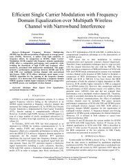
loop, (2) outer ball <strong>and</strong> beam control loop. The design<br />
strategy is to first stabilize the inner loop followed by the<br />
outer loop.<br />
II.<br />
MATHEMATICAL MODELING<br />
The <strong>Ball</strong> & Beam Control system is a multi-loop system<br />
which comprises of two parts. One is the mathematical<br />
model of the dc motor followed by mathematical model of<br />
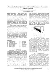
the ball <strong>and</strong> beam system. The typical ball & beam control<br />
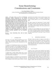
system is shown in the Fig. 1.<br />
Fig.2 Block Diagram of <strong>Ball</strong> <strong>and</strong> Beam Control System<br />
<strong>Ball</strong><br />
<strong>Ball</strong> Position<br />
Motor<br />
Fig.1 <strong>Ball</strong> <strong>and</strong> Beam Control System<br />
Desired<br />
Position<br />
Beam<br />
There are number of techniques to design the PID<br />
controller which involves Ziegler <strong>and</strong> Nichols, SISO Tool,<br />
ITAE Equations, root locus, frequency response etc. In our<br />
design, we have used the ITAE equations <strong>for</strong> the PD <strong>and</strong><br />
PID gains computation. The per<strong>for</strong>mance index ITAE<br />
provides the best selectivity of the per<strong>for</strong>mance indices;<br />
that is, the minimum value of the integral is readily<br />
discernible as the system parameters are varied. The<br />
general <strong>for</strong>m of the per<strong>for</strong>mance integral is<br />
Fig.1 shows that there are three main components are<br />
involved in the system which includes moments <strong>and</strong><br />
<strong>for</strong>ces acting on them, the motor, the beam, <strong>and</strong> the ball.<br />
Using the equation <strong>for</strong> the sum of <strong>for</strong>ces <strong>and</strong> torques the<br />
final mathematical model that we get is<br />
GT<br />
G<br />
Φ<br />
I<br />
() s<br />
() s<br />
in<br />
,<br />
g<br />
=<br />
2<br />
⎛ ⎞<br />
2⎜<br />
2 ⎛ a ⎞<br />
s 1+<br />
⎟<br />
⎜ ⎟<br />
⎝<br />
5 ⎝ a′<br />
⎠ ⎠<br />
Based on the motor parameters, Km<br />
= 0.7/ rev/ sce/<br />
volts,<br />
−6 2<br />
τ = 0.014 Sec , J = 1.4× 10 Kg− m , motor model can<br />
be written as<br />
θ ( s)<br />
0.7<br />
Gm<br />
( s)<br />
= =<br />
I ( s)<br />
0.014s<br />
+ 1<br />
in<br />
Based on the ball <strong>and</strong> beam specifications of<br />
a= 1.5cm(radius of the ball) <strong>and</strong> a' = 9.4227cm(<strong>for</strong> 2π)<br />
the transfer function of ball <strong>and</strong> beam can be written as<br />
1<br />
() s =<br />
1.713s<br />
<strong>Ball</strong>Beam( Open) 2<br />
0.7<br />
() s =<br />
0.0234s + 1.713s + 1.1991s<br />
4 3 2<br />
(1)<br />
(2)<br />
(3)<br />
The overall transfer function of the ball <strong>and</strong> beam in open<br />
loop will become:<br />
(4)<br />
III. PID CONTROLLER DESIGNING METHODOLOGY<br />
I<br />
G<br />
T<br />
= ∫<br />
0<br />
motor<br />
f ( e(<br />
t),<br />
r(<br />
t),<br />
y(<br />
t),<br />
t)<br />
dt<br />
The procedure <strong>for</strong> calculating the PID gains using the ITAE<br />
equations is as follow.<br />
Step-1: In this calculation method first we multiply the<br />
general <strong>for</strong>m of the PID with the open loop transfer<br />
function.<br />
Step-2: The characteristics equation is compared with the<br />
st<strong>and</strong>ard ITAE equations. The value of damping ratio (ζ) is<br />
constant that is 0.6.<br />
Using st<strong>and</strong>ard equations of ITAE the PD <strong>and</strong> the PID<br />
controllers designed <strong>for</strong> the inner <strong>and</strong> outer loop can be<br />
written as respectively [14,15]:<br />
( <strong>Controller</strong> )(<br />
s)<br />
= 2s<br />
+ 11<br />
2<br />
5s<br />
+ 6s<br />
+ 0. 2<br />
G <strong>Ball</strong> ( <strong>Controller</strong> )<br />
( s)<br />
=<br />
s<br />
The main advantage <strong>for</strong> using the ITAE equation method<br />
<strong>for</strong> the calculation of gain is that there is no requirement <strong>for</strong><br />
any graph or chart like the root locus <strong>and</strong> the bode plot.<br />
These equations can easily be used <strong>for</strong> the gains calculation<br />
of up to 6th order characteristics equation. After calculating<br />
the gains from the ITAE equations we require the little bit<br />
tuning of the gains.<br />
(5)<br />
(6)<br />
(7)<br />
The block diagram of the whole system is shown in Fig.2.<br />
The system consists of two loops: (1) Inner motor control<br />
Proceedings of International Bhurban Conference on Applied Sciences & Technology,<br />
Islamabad, Pakistan, 10 - 13 January, 2011 155
IV. SIMULATION RESULT OF UNCONSTRAINT SYSTEM<br />
1<br />
In this section the simulation results of the system with the<br />
controllers are presented. First we see the step response of<br />
the overall system without controller. The block diagram<br />
of the system without controller with unity feedback <strong>and</strong><br />
its step response is shown in the Fig.3 <strong>and</strong> Fig. 4<br />
respectively.<br />
0.8<br />
0.6<br />
0.4<br />
0.2<br />
Reference Signal<br />
Inner loop Response with <strong>Controller</strong><br />
0<br />
0 0.5 1 1.5 2 2.5 3 3.5 4 4.5 5<br />
Fig.3: Block Diagram of the Overall Closed Loop system with<br />
unity feedback without controller<br />
Fig.6: Step response of inner closed loop with PD controller<br />
120<br />
100<br />
80<br />
Output of the closed loop system without controller<br />
1.4<br />
1.2<br />
Reference Signal<br />
System Output<br />
60<br />
1<br />
40<br />
0.8<br />
Output<br />
20<br />
0<br />
0.6<br />
-20<br />
0.4<br />
-40<br />
-60<br />
0.2<br />
-80<br />
0 5 10 15 20 25 30<br />
Time<br />
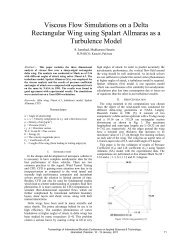
Fig.4: Step Response of the Overall Closed Loop system with unity<br />
feedback without controller<br />
0<br />
0 1 2 3 4 5 6 7 8 9 10<br />
Fig.7: Step response Overall closed loop system with controllers<br />
From this simulation result e can analyze that the system<br />
in close loop without controllers is unstable. To stabilize<br />
the system we start from the inner loop <strong>and</strong> apply the PD<br />
controller. The block diagram of the inner loop with PD<br />
controller <strong>and</strong> its response is shown in the Fig.5 <strong>and</strong> Fig.6<br />
respectively.<br />
From the response we can see that the overall system has<br />
been stabilized with a settling time of 2.3 Sec. Although the<br />
2.3sec is much high settling time but it is the requirement<br />
because at the low settling time the motor starts to take<br />
jerks <strong>and</strong> through the ball outside the beam. The dire time<br />
of the system with PID controller is 0.444 Sec <strong>and</strong> the<br />
percentage overshot is 28.9%.<br />
Fig.5: Block Diagram of inner closed loop with PD controller<br />
Form this result it is clear that the inner loop is stable now<br />
with a settling time of 0.08 Sec. In the next step the PID<br />
controller will be applied in the outer loop to stabilize the<br />
overall system.<br />
The response of the overall system with PID controller is<br />
shown in Fig.7 in right column:<br />
IV<br />
SIMULATION RESULT OF CONSTRAINT<br />
SYSTEM<br />
All real-world applications of feedback control involve<br />
control actuator with amplitude <strong>and</strong> rate limitations. The<br />
control design techniques that ignore these actuator limits<br />
may cause undesirable transient response, degrade the close<br />
loop per<strong>for</strong>mance <strong>and</strong> may cause even closed-loop<br />
instability. Thus actuator saturation constitutes fundamental<br />
limitations of many linear control design techniques <strong>and</strong><br />
has attracted the attention of numerous researchers,<br />
especially in the last decade.<br />
Proceedings of International Bhurban Conference on Applied Sciences & Technology,<br />
Islamabad, Pakistan, 10 - 13 January, 2011 156
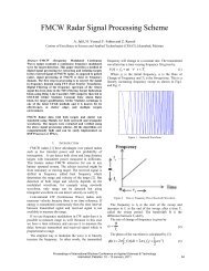
The response of the ball on the beam system with<br />
saturation [0 0.5] applied is shown in Fig.8 below:<br />
20<br />
15<br />
10<br />
Reference Signal<br />
Unconstraint System<br />
Constraint System<br />
In the Fig.9 G in represent the motor transfer function <strong>and</strong><br />
~<br />
out<br />
~<br />
G represent the transfer function of the ball <strong>and</strong> beam.<br />
This configuration can be decoupled into linear <strong>and</strong><br />
nonlinear parts <strong>for</strong> the stability <strong>and</strong> per<strong>for</strong>mance analysis as<br />
shown in Fig.10.<br />
5<br />
Output<br />
0<br />
-5<br />
-10<br />
-15<br />
-20<br />
0 5 10 15 20 25 30<br />
Time<br />
Fig.8: Step response Overall closed loop Constraint system with<br />
controllers<br />
In the simulations shown in Fig.8 the pulses are applied to<br />
the system <strong>and</strong> the output is observed. From the above<br />
results we can see that the after applying the actuator<br />
saturation to the system, the system become unstable. The<br />
black dotted line is the response of the constraint closed<br />
loop system.<br />
V. ANTI-WINDUP CONTROLLER DESIGN<br />
Generally two basic types of AWC structures are used.<br />
One in which the AWC output is directly added into the<br />
output of system as in [1,3,4] <strong>and</strong> other in which AWC<br />
output is directly fed into controller like [8]. The first one<br />
is applicable to most of the engineering problems as<br />
shown in [10]. So the architecture we use is of first type in<br />
which AWC can be incorporated <strong>for</strong> existing<br />
unconstrained control scheme.<br />
In case of cascade control system, the plant G in (s) has<br />
input saturation which also disturbs the per<strong>for</strong>mance of<br />
outer loop. The AWC parameters M1 <strong>and</strong> M2 are chosen<br />
as part of co-prime factorization of plants G p1 (s) <strong>and</strong> G p2 (s)<br />
respectively as shown in Fig.9 [9].<br />
Fig.10: Equivalent of Fig.9. Decoupling AWC into nonlinear loop <strong>and</strong><br />
disturbance filters<br />
The role of ( M1− I −M2<br />
−I)<br />
in nonlinear loop is pivotal in<br />
extracting the system from saturation back to linear<br />
behavior.<br />
The coprime factorization of G p1 (s) <strong>and</strong> G p2 (s) can be<br />
written as:<br />
G () s = N () s M () s<br />
(8)<br />
−1<br />
p1 1 1<br />
G () s = N () s M () s<br />
−1<br />
p2 2 2<br />
Full-order right co-prime factorization of both plants can be<br />
described as follows:<br />
(9)<br />
(10)<br />
(11)<br />
Here F 1 <strong>and</strong> F 2 are used to determine co-prime<br />
factorizations of G p1 <strong>and</strong> G p2 respectively <strong>and</strong> chosen such<br />
that A p1 + B p1 F 1 <strong>and</strong> Ap 2 + B p2 F 2 are Hurwitz matrix. In this<br />
case the mapping Γ<br />
p<br />
: ulin → yd , y is given as<br />
1 d 2<br />
(12)<br />
Fig.9: Cascade control system with conditioning using M 1 <strong>and</strong> M 2<br />
Proceedings of International Bhurban Conference on Applied Sciences & Technology,<br />
Islamabad, Pakistan, 10 - 13 January, 2011 157
Then in order to minimize the L 2<br />
norm of the system to a<br />
minimum value γ we have the following objective<br />
function [9]:<br />
d<br />
~ ~<br />
1<br />
0<br />
T<br />
⎡P<br />
⎤<br />
J = xp ⎢ xp + Wr ulin − ( Fx<br />
1 p1+ u) − ( F2xp2<br />
+ u)<br />
dt 0 P<br />
⎥<br />
⎣ 2 ⎦<br />
~<br />
2<br />
~<br />
2<br />
2<br />
p1 1 p1 p1 p2 2 p2 p2<br />
γ<br />
lin<br />
+ W C x + D u + W C x + D u − u < 0<br />
2<br />
(13)<br />
Output<br />
1<br />
0.8<br />
0.6<br />
0.4<br />
Reference Signal<br />
Constraint + Full Order Robust AWC<br />
By adding the dead-zone nonlinearity <strong>and</strong> after applying<br />
the Schur Complement, S-procedure <strong>and</strong> Congruence<br />
trans<strong>for</strong>mation, we finally get the <strong>LMI</strong> (14) <strong>for</strong> robust full<br />
order anti-windup compensator.<br />
0.2<br />
0<br />
0 5 10 15 20 25 30<br />
Time<br />
Fig.11: Step Response of the constraint system with robust full order<br />
dynamic <strong>Anti</strong>-windup controller<br />
(14)<br />
Here Q 1 > 0, Q 2 > 0, U > 0, <strong>and</strong> γ > 0. Here Q 1 = P 1 -1 , Q 2 =<br />
P 2 -1 , U = V -1 , L 1 = F 1 Q 1 <strong>and</strong> L 2 = F 2 Q 2 . Hence the robust<br />
AWC <strong>for</strong> the cascade control system can be designed by<br />
minimizing γ <strong>for</strong> <strong>LMI</strong> (14). The weighted value W p1 , W p2<br />
<strong>and</strong> W r are positive definite weighting matrices that reflect<br />
the relative importance of per<strong>for</strong>mance <strong>and</strong> robustness,<br />
respectively, <strong>and</strong> chosen by designer.<br />
VI. SIMULATION RESULTS OF CONSTRAINT<br />
SYSTEM WITH ANTI-WINDUP CONTROLLER<br />
As we have seen in Fig. 8 that incorporating the constraint<br />
to the system produces the instability in the system. To<br />
produce the stability in the constraint system the <strong>Anti</strong>-<br />
<strong>Windup</strong> controller will be incorporated.<br />
The value of F 1 <strong>and</strong> F 2 that we get after solving <strong>LMI</strong> (14)<br />
is as follow:<br />
F1<br />
= [0.0001 0.0038]<br />
F = ×<br />
2<br />
−14<br />
1 10 *[0 0.3301]<br />
(15)<br />
The response of the constraint system with the full order<br />
robust anti-windup controller is shown in Fig. 11 in the<br />
left column:<br />
From the simulation result shown in Fig.11 that by<br />
incorporating the anti-windup controller the overall system<br />
has become stable. Although there is steady state error, but<br />
it is always present because we have limit the output pf the<br />
actuator.<br />
VII.<br />
CONCLUSION<br />
In this paper we design the PID controller <strong>for</strong> the ball on<br />
the beam system using the ITAE equations. The<br />
incorporation of the actuator limitation produces the<br />
instability in the system. The full order anti-windup<br />
controller is designed <strong>for</strong> the cascaded ball on the beam<br />
control system. The <strong>LMI</strong> based anti-windup controller<br />
gives the optimal results with dynamic gains <strong>and</strong> it only<br />
dependent on plant parameter. By incorporating the full<br />
order anti-windup controller the constraint system has<br />
become stable <strong>and</strong> there is no more instability in the system.<br />
ACKNOWLEDGEMENT<br />
I gratefully acknowledge the support of Sir Ashab Mirza<br />
(Associate Professor, IIEE), Sir Yousuf Kakakhail<br />
(Professor, PIEAS) <strong>for</strong> their guidance as my teacher <strong>and</strong><br />
course in-charge. I would also like to thanks Mr. Ufaq Shah<br />
who helped us a lot in implementing the <strong>Ball</strong> & Beam<br />
Control System.<br />
Proceedings of International Bhurban Conference on Applied Sciences & Technology,<br />
Islamabad, Pakistan, 10 - 13 January, 2011 158
REFRENCES<br />
[1]. Weston P, Postlethwaite (2000) Linear Conditioning <strong>for</strong> systems<br />
containing saturating actuator, Automatica 36:1347-1354<br />
[2]. Turner MC, Herrmann G, Postlethwaite I (2007) An<br />
Architecture <strong>for</strong> design <strong>and</strong> analysis of high per<strong>for</strong>mance robust<br />
anti-windup compensators. IEEE Trans Automat Control<br />
52(9):1672-1679<br />
[3]. Turner MC, Postlethwaite I (2004) A new perspective on static<br />
<strong>and</strong> low order anti-windup synthesis. Int J Control 77(1):27-44<br />
[4]. Turner MC, Herrmann G, Postlethwaite I (2007) Incorporating<br />
robustness requirements into anti-windup design. IEEE Trans<br />
Automat Control 52:1842–1855<br />
[5]. Preitl Z, Bauer P (2007) Cascade control Solution <strong>for</strong> traction<br />
motor <strong>for</strong> hybrid electric vehicles, Acta Polytech Hung 4(3):75-<br />
88<br />
[6]. Herrmann G, Turner MC, Postlethwaite I (2004) Practical<br />
implementation of a novel anti-windup scheme in a HDD-Dual-<br />
Stage servo system. IEEE Trans Mechatron 9(3):580–592<br />
[7]. Skogestad S, Postlethwaite I (2005) Multivariable Feedback<br />
Control analysis <strong>and</strong> design, 2 nd edn, Wiley, New York.<br />
[8]. Edwards C, Postlethwaite I (1999) An anti-windup scheme with<br />
closed loop stability considerations, Automatica 35:761-765<br />
[9]. A. Ahmed, M. Rehan, N. Iqbal (2010) Robust Full order antiwindup<br />
compensator design <strong>for</strong> a class of cascade control<br />
systems using <strong>LMI</strong>s.<br />
[10]. Grimm G., Postlethwaite I, Teel A.R., Turner M.C., Zaccarian L.<br />
(2001) Linear matrix inequalities <strong>for</strong> full <strong>and</strong> reduced order antiwindup<br />
synthesis. In: Proceedings of the American control<br />
conference, Arlington, pp 4134–4139.<br />
[11]. Jeff Lieberman, (2004) A Robotic <strong>Ball</strong> Balancing Beam,<br />
Department Of Mechanical Engineering, Massachusetts Institute<br />
of Technology, USA<br />
[12]. G. J. Kenwood, (1982) Modern Control of the classic ball <strong>and</strong><br />
beam problems, Massachusetts Institute of Technology,<br />
Cambridge, MA.<br />
[13]. Evencio A. Rosales (2004) A <strong>Ball</strong>-on-Beam Project Kit,<br />
Department Of Mechanical Engineering, Massachusetts Institute<br />
of Technology, USA.<br />
[14]. M. Amjad, Kashif M. I, S. S. Abdullah, Z. Shareef (2010) Fuzzy<br />
Logic Control of <strong>Ball</strong> <strong>and</strong> Beam System, ICETC/IEEE Shinghai,<br />
China<br />
[15]. M. Amjad, Kashif M. I, S. S. Abdullah, Z. Shareef (2010) A<br />
Simplified intelligent controller <strong>for</strong> <strong>Ball</strong> <strong>and</strong> beam system,<br />
ICETC/IEEE Shinghai, China.<br />
[16]. Francis H. Raven. Automatic Control Engineering, 5th ed,<br />
McGraw-Hill Inc.<br />
[17]. D' Azzo, John J <strong>and</strong> Houpis, C. H. (1995). Linear Control System<br />
Analysis <strong>and</strong> Design: Conventional <strong>and</strong> Modem, 4th ed.,<br />
McGraw-Hill Inc.<br />
Proceedings of International Bhurban Conference on Applied Sciences & Technology,<br />
Islamabad, Pakistan, 10 - 13 January, 2011 159